
I:\CIRC\MSC\920.WPD
INTERNATIONAL MARITIME ORGANIZATION
E
4 ALBERT EMBANKMENT
LONDON SE1 7SR
Telephone: 0171-735 7611
Fax:
0171-587 3210
Telex:
23588 IMOLDN G
IMO
Ref. T1/3.02
MSC/Circ.920
15 June 1999
MODEL LOADING AND STABILITY MANUAL
1
The Maritime Safety Committee, at its seventy-first session (19 to 28 May 1999), noting the need
for Administrations and industry to be provided with guidance on the preparation of loading and stability
manuals, using a uniform layout as well as agreed terms, abbreviations and symbols which are important
for the correct use of such manuals by mariners, approved the Model Loading and Stability Manual set out
in the annex.
2
Member Governments are invited to use the annexed Model and bring it to the attention of all
parties concerned.
***


MSC/Circ.920
Information categories are defined as follows:
1
.1
category 1A information is information which includes all basic data necessary to obtain the trim
and stability characteristics of the ship;
.2
category 1B information is optional information which is deemed, by owners, to be necessary
and useful material appropriate to the operation of the ship;
.3
category 2 information is information which provides the master with ready means of ensuring
that the ship's stability parameters for the given service and condition of loading lie within the
limits required by the Administration; and
.4
category 3 information is supportive information, not necessary for the use on board, which may
be required by Administrations for the verification of the information under categories 1 and 2.
I:\CIRC\MSC\920.WPD
ANNEX
MODEL LOADING AND STABILITY MANUAL
Table of contents
Section
1 - Identification and approval
Section
2 - Guidance to the master
2.1
Introduction
2.2
Terms, symbols and units
2.3
Explanations to the manual
2.4
Operation of the ship
2.5
Typical approved loading conditions
2.6
Control of stability, trim and longitudinal strength
Section
3 - Technical information (Category 1 and 2)
1
3.1
Capacity plan
3.2
Cargo space information
3.3
Tank space information
3.4
Hydrostatic particulars
3.5
Lightship particulars
3.6
Load line particulars
3.7
Stability limits
3.8
Longitudinal strength criteria
3.9
Other operational restrictions
Section
4 - Reference information (Category 3)
*
4.1
Inclining experiment report
4.2
Intact stability criteria
4.3
Other information

MSC/Circ.920
ANNEX
Page 2
I:\CIRC\MSC\920.WPD
Section 1 - Identification and approval
1.1
This section should contain information deemed suitable by the Administration to clearly identify
the ship with regard to the applicability and approval of this manual.
1.2
The information in this section should include:
.1
ship's name and type/purpose of ship;
.2
name of builder and yard number;
.3
date of build/conversion (keel laying or delivery);
.4
particulars of classification;
.5
nationality, port of registry and official number;
.6
principal dimensions;
.7
other information, if deemed necessary; and
.8
IMO Number.
1.3
The pages of the manual should be numbered beginning with section 1. The total number of pages
should be stated in this section.
1.4
The approval of the manual by, or on behalf of, the Administration should be stated in this section
together with the prominent indication of any restrictions regarding the area or season of operation or any
other relevant issues. This approval should, in addition, be certified on the front cover of the certificate.
Section 2 - Guidance to the master
2.1
Introduction
2.1.1
The introduction should address the general purpose of the manual, i.e.:
.1
to provide all necessary information to the master for the proper loading and ballasting of
the ship and for the control of stability, draught and structural integrity, if needed;
.2
to satisfy the requirements of the flag State Administration with regard to approval
according to regulation II-1/22 of the International Convention for the Safety of Life at
Sea, 1974, as amended, regulation 10 of the International Convention on Load Lines, 1966
and regulation III/10 of the 1993 Torremolinos Protocol; and
.3
to stress the need for the masters to exercise prudence and good seamanship, having regard
to the season of the year, weather forecasts and the navigational zone, and to take the
appropriate action as to speed and course warranted by the prevailing conditions.

MSC/Circ.920
ANNEX
Page 3
ISO 7462 and ISO 7463, as revised by 2000.
1
I:\CIRC\MSC\920.WPD
2.1.2
A statement should, if applicable, identify the optional information contained in the manual, which
may be deemed by owners to be useful material appropriate to the operation of the ship, and the accuracy
and correctness of which falls under the responsibility of the owners. This type of information is referred
to as category 1B information.
2.2
Terms, symbols and units
2.2.1
It is of utmost importance for the practical use of the manual by the mariner that terms, symbols
and units comply with relevant ISO standards. A statement of this compliance should be given in this
1
section.
2.2.2
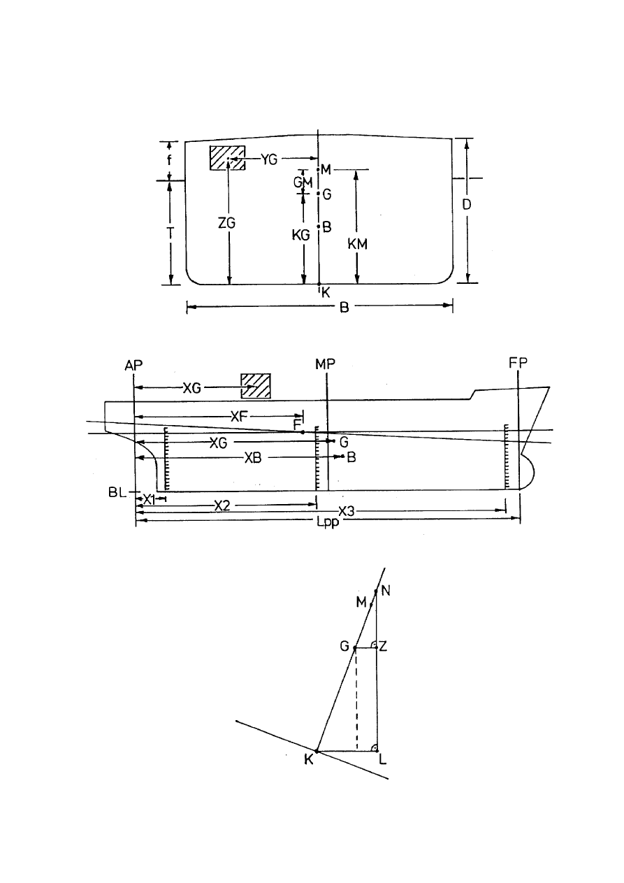
The terms, symbols and units considered necessary in a typical loading and stability manual are
shown in table 1. Sketches, such as shown in figures 1, 2 and 3, depicting the above symbols, should be
included in the manual as deemed appropriate.
MSC/Circ.920
ANNEX
Page 4
I:\CIRC\MSC\920.WPD
Table 1: Terms, symbols and units
Term
Symbols used
SI-unit
After perpendicular
Fore perpendicular
Mid between perpendiculars
Baseline
Bottom of keel
Heel angle
Length (usually Lpp for merchant ships)
Breadth
Depth
Freeboard
Keel draught
Aft keel draught
Keel draught, reading at aft draught mark
Reference keel draught
Forward keel draught
Keel draught, reading at forward draught mark
Mean keel draught = 0.5 (T + T )
KA
KF
Keel draught, reading at mid draught mark
Hull deflection = T
- T
KM
K
Trim = T - T
KF
KA
Displacement volume
Displacement mass
Displacement mass per centimetre change of draught
Waterplane area coefficient
x-coordinate of centre of buoyancy
x-coordinate of centre of flotation
x-coordinate of centre of gravity
y-coordinate of centre of gravity
z-coordinate of centre of gravity
Corrected z-coordinate of centre of gravity = KG +
)
KG
z-coordinate of metacentre
Metacentric height
Corrected metacentric height = GM -
)
KG
Righting lever
Value of stability crosscurve
Heeling lever of lateral wind force
Transverse moment of inertia of the surface of liquids
Moment to change trim one centimetre
Moment to change trim one metre
Natural roll period
Rolling coefficient
Wind pressure
Ship's speed
x-coordinate of aft draught mark
x-coordinate of mid draught mark
x-coordinate of fore draught mark
Density
AP
FP
MP
BL
BK
N
L
B
D
f
T
K
T
KA
T
KAR
T
KC
T
KF
T
KFR
T
KM
T
KR
d
t
L; DISV
)
; DISM
TPC
C
WP
x ; XB
B
x ; XF
F
x ; XG
G
y ; YG
G
KG
KG
c
KM
GM
GM
c
GZ
l ; LK
K
l ; LV
V
i ; IB
B
MTC
MTM
T
N
C
N
p
V
V
-
-
-
SI-symbol:
D
-
-
-
-
-
rad; (°)
m
m
m
m
m
m
m
m
m
m
m
m
m
m
m
3
kg; (t)
kg/cm; (t/cm)
-
m
m
m
m
m
m
m
m
m
m
m
m
m
4
Nm/cm; (tm/cm)
Nm/m; (tm/m)
s
-
N/m
2
m/s; (kn)
m
m
m
kg/m ; (t/m )
3
3
MSC/Circ.920
ANNEX
Page 5
I:\CIRC\MSC\920.WPD
Figure 1
Figure 2
Figure 3

MSC/Circ.920
ANNEX
Page 6
I:\CIRC\MSC\920.WPD
2.3
Explanations to the manual
2.3.1
This subsection should contain explanations to this manual, in particular to technical information
in section 3, if deemed necessary. This should include but not be limited to:
.1
reference planes and signs of trim;
.2
applicability of hydrostatic data with regard to trim;
.3
applicability of stability limits with regard to trim, height of deck cargo or other
parameters; and
.4
general advice on the use of tables or diagrams with regard to accuracy and interpolation.
2.3.2
Explanations given in this subsection should be repeated at the specific technical information, table
or relevant issue in a suitable manner.
2.4
Operation of the ship
2.4.1
This sub-section should characterize the lightship with regard to stability, trim, heeling-moment due
to asymmetrical equipment and longitudinal stress parameters.
2.4.2
If applicable, the preferred compensation of asymmetrical light ship mass by ballast, consumables
or cargo should be explained. A warning against compensation by solid bulk cargo should be given.
2.4.3
The concept of the distribution of consumables in different stages of consumption, such as full,
partly filled and minimal arrival conditions, should be explained including the effect on KG in loaded
condition.
2.4.4
The concept of the compensation of increase of KG due to fuel consumption during the voyage by
taking ballast should be explained. A suitable table or diagram should be used, where appropriate.
2.4.5
The general stress situation in terms of bending moments and shear forces should be commented
for typical and, if necessary, for unusual loading conditions. Warnings should be given against extreme
stress situations which may arrive with specific distributions of cargo and/or ballast, e.g. filling the forepeak
or afterpeak. Similar warnings should be given against undue torsional moments if appropriate.
2.4.6
The principal ballast patterns should be explained for the carriage of heavy deck cargo, like
containers, or light cargo in the hold, like ro/ro-vehicles.
2.4.7
Specific information should be given regarding the effect of hoisted crane booms, filled swimming
pool or other heavy top masses on the ship's stability, and the correct use of anti-rolling devices and/or
heeling tanks, if applicable.
2.4.8
All relevant operating limits with regard to loading and distribution of cargo and ballasting should
be listed and explained, as for example:
.1
maximum draught according to Load Line Certificate;

MSC/Circ.920
ANNEX
Page 7
I:\CIRC\MSC\920.WPD
.2
maximum KG -values according to intact stability criteria or damage stability criteria;
c
.3
maximum allowable shear forces and bending moments;
.4
restrictions to deck stowage and trim due to SOLAS-sight lines;
.5
minimum draught foreward and aft with regard to seakeeping;
.6
maximum draught foreward due to minimum bow height requirement;
.7
maximum stack loads for container stacks;
.8
maximum load per area for break bulk cargoes; and
.9
maximum load per hold for bulk cargoes.
Reference should be made to the Damage Control Manual and the Cargo Securing Manual, if applicable.
2.4.9
A general warning should be given that tanks which are not in use should, where practical, be either
completely empty or completely filled up, in particular where the stability is marginal.
2.4.10 A general warning should be given of the reduction of stability by a steady angle of heel of the ship.
It is essential to keep the ship upright at all times by a symmetrical distribution of masses.
2.5
Typical approved loading conditions
2.5.1
As a minimum, the following loading conditions should be compiled and calculated for any ship
in accordance with MSC/Circ.456:
.1
lightship condition;
.2
docking condition;
.3
loading conditions as stipulated in 3.5.1, 4.2.5 and 4.5.7 of the Intact Stability Code
(resolution A.749(18)), as amended; and
.4
table of summary of loading conditions.
2.5.2
Assumptions for calculating loading conditions should be in accordance with 3.5.2, 4.1.8 and 4.5.8
of the Intact Stability Code, as amended. Where icing is likely to occur the loading conditions should take
this into account.
2.5.3
As calculated loading conditions will be used by the master to obtain a realistic picture of the cargo
carrying capabilities of the ship, it is recommended to include a limited number of fully loaded conditions
with approximately half capacity of consumables on departure. The consequential surplus of cargo carrying
capacity may be partly used for low ballast if the excess cargo is to be loaded on deck. The subsequent
arrival condition with 10% consumables should be provided as well.

MSC/Circ.920
ANNEX
Page 8
I:\CIRC\MSC\920.WPD
2.5.4
If, due to the nature of the cargo and its typical stowage pattern, stability may become the limiting
parameter for the loading concept in general (e.g., containerships, ro-ro ships, ships carrying timber on
deck), the calculated loading conditions should present "limit conditions" with regard to load line and
stability requirements either for departure or arrival or both.
2.5.5
Each presented condition of loading should include:
.1
A sketch of the ship indicating pictorially the main items of deadweight included in the
displacement, side view and top view if useful.
.2
A table showing lightship mass and all components of the deadweight together with the
positions of their centres relative to the defined reference planes.
The summation should show the displacement and the positions of its centre. Positions
should be shown along the vertical and longitudinal axes. For containerships and ro-ro
ships, the inclusion of the transverse co-ordinate is recommended. The free surface
moments of slack tanks for zero degree heel should be included in this table in accordance
with 3.3 of the Intact Stability Code, as amended.
.3
A diagram showing the curve of righting levers plotted against the angle of inclination.
The righting levers are to be corrected for free surface effects in accordance with 3.3 of the
Intact Stability Code, as amended. Wind and/or other heeling lever curves should be
superimposed on the diagram as appropriate. The scales used in this diagram should be
the same for each loading condition in the manual.
.4
A summary of the appropriate condition should contain as a minimum:
.1
displacement;
.2
corresponding draught (i.e. draught at centre of flotation);
.3
moment to change trim one unit (metre or centimetre);
.4
longitudinal position of centre of buoyancy;
.5
longitudinal position of centre of mass;
.6
longitudinal position of centre of flotation;
.7
trim over perpendiculars;
.8
draught at forward perpendicular;
.9
draught at after perpendicular;
.10
draught at mid between perpendiculars;
.11
total free surface moment for initial stability;

MSC/Circ.920
ANNEX
Page 9
I:\CIRC\MSC\920.WPD
.12
vertical position of the transverse metacentre (for trimmed condition if trim
exceeds 1% of the length of the ship);
.13
vertical position of the ship's centre of mass, uncorrected and corrected for free
surface effects;
.14
transverse metacentric height uncorrected and corrected for free surface effects;
and
.15
a statement giving the limiting value or values of stability parameters taken from
data under 3.6 and the comparison with corresponding values achieved.
.5
Draught and other hydrostatic data to be obtained from immersed gross volume in sea
water (
D
= 1.025 t/m ). If the ship is intended to operate in areas of less water density the
3
appropriate immersed gross volume may be used if agreed by the flag State
Administration.
.6
Draught statements should refer to bottom of keel. This should be clearly indicated.
2.5.6
Each calculated loading condition should be commented or explained highlighting the specific
features of the particular condition with regard to:
.1
operating limits (see 2.4.8);
.2
ballast operations between departure and arrival due to fuel consumption, water soaking
of deck cargo or other reasons;
.3
limitations to stowage factor of cargo or to average container masses per tier;
.4
restrictions to the positioning of ship's equipment and other heavy masses or usage of
swimming pool;
.5
amount and distribution of consumables;
.6
minimum filling of slack ballast tanks to avoid excessive sloshing (in the case of high initial
stability); and
.7
any other important aspects.
2.6
Control of stability, trim and longitudinal strength
2.6.1
Reference to the ship's approved loading and stability computer should be made and to the user
guide provided with this computer, if applicable.
2.6.2
A simple guidance should be given for the manual calculation of stability, draught and trim, which
may be required for the control of loading conditions outside the scope of conditions under 2.5 on ships
not equipped with an approved loading and stability computer, or if such computer fails. The use of
suitable form sheets is recommended for this purpose.

MSC/Circ.920
ANNEX
Page 10
I:\CIRC\MSC\920.WPD
2.6.3
This subsection should, if appropriate, present the following form sheets for:
.1
compiling mass and position of consumables and stores;
.2
compiling mass and position of ballast;
.3
compiling mass and position of cargo;
.4
compiling mass and position of fishing gear;
.5
compiling mass and position of ice accretion;
.6
compiling displacement and position of centre of displacement and evaluating draught and
trim; and
.7
plotting a righting lever curve and, where appropriate, a wind heeling lever curve.
2.6.4
The form sheet under 2.6.3.3 should suit the particular type or types of cargo the ship is intended
to carry, i.e. a different layout may be required for:
.1
break bulk;
.2
containers;
.3
ro/ro-vehicles;
.4
bulk cargoes (solid or liquid);
.5
fish; and
.6
ice.
For cargoes with a structured stowage pattern like containers or ro/ro-vehicles, separate form sheets for
calculating the vertical and the longitudinal position of the centre of cargo mass may be useful.
MSC/Circ.920
ANNEX
Page 11
I:\CIRC\MSC\920.WPD
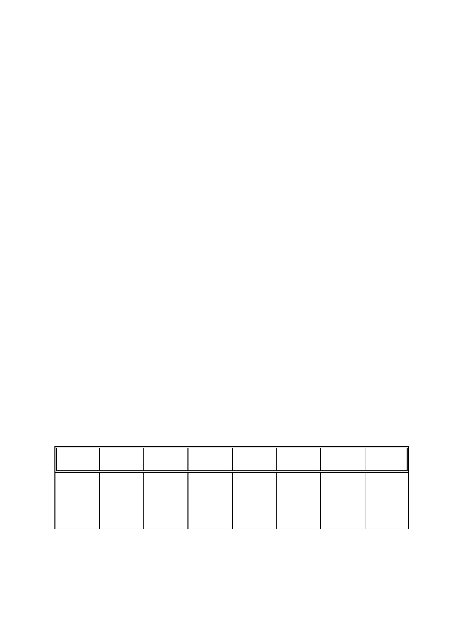
2.6.5
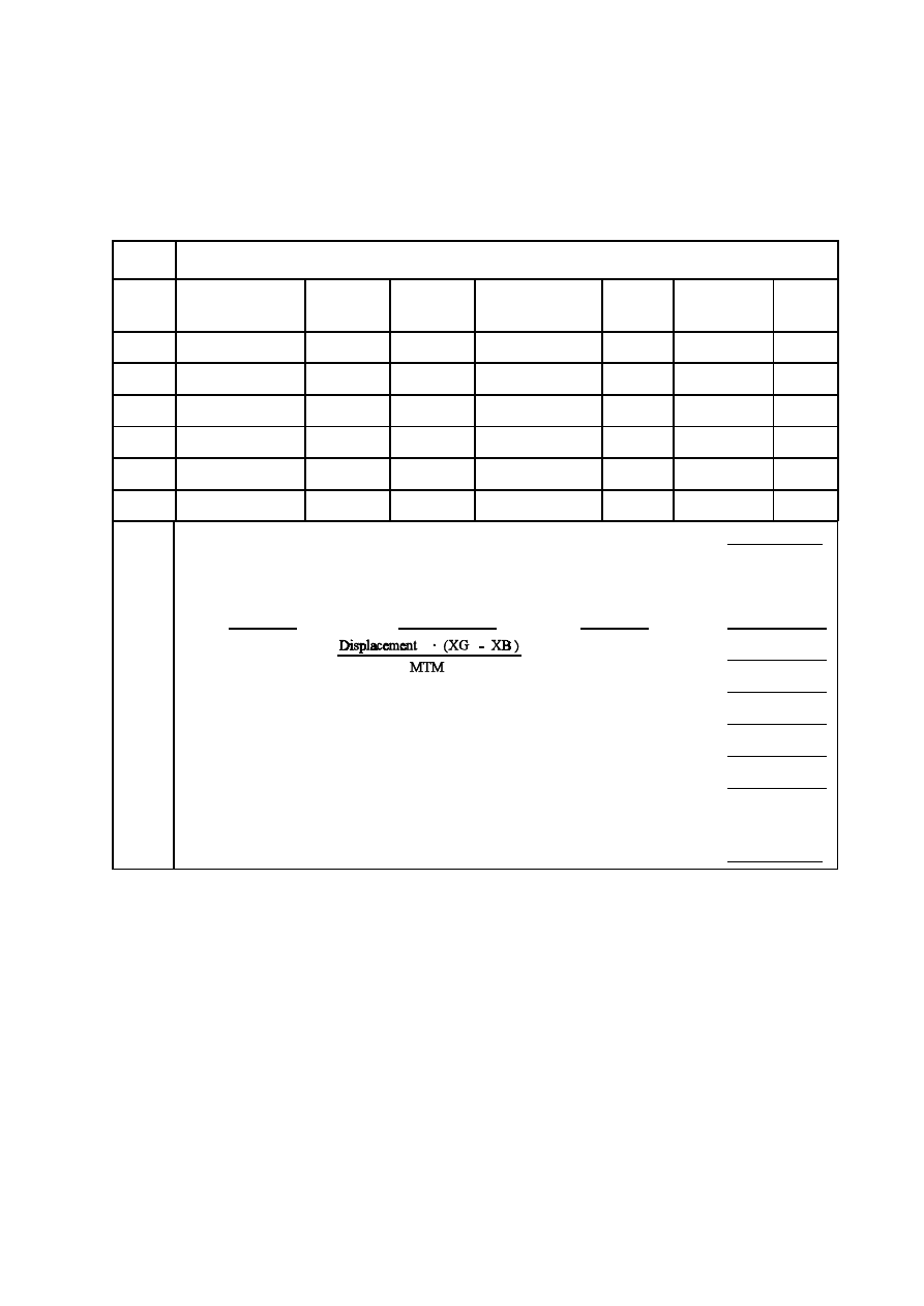
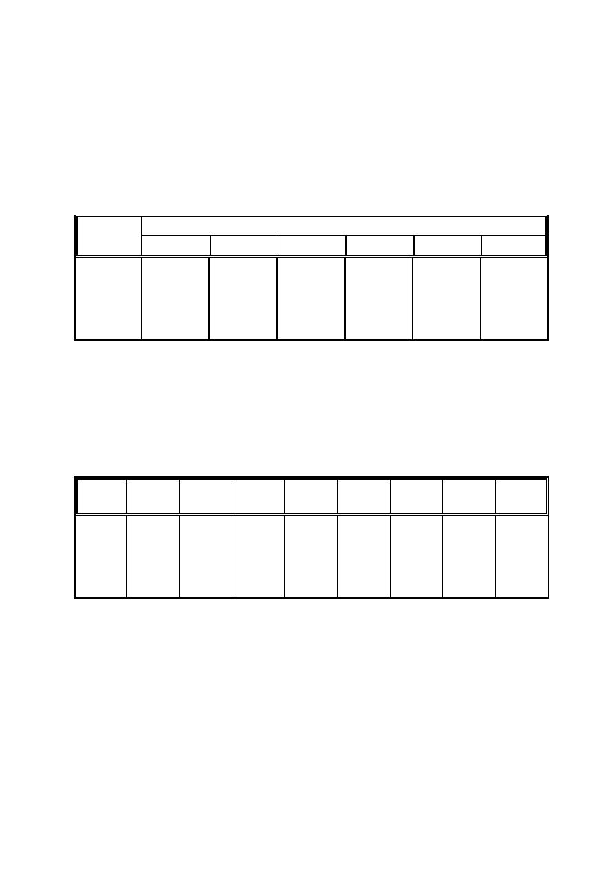
A model of the form sheets under 2.6.3.4 and 2.6.3.5 is shown in the tables 2 and 3 below.
Line
Manual calculation of stability and trim
0
Item
Mass
t
XG
m
Long. mom.
t . m
ZG
m
Vert. mom.
t . m
i
@@
DD
B
t . m
1
Light ship
4055.4
47.55
192835.2
9.75
39540.3
-
2
Consumables
3
Ballast
4
Cargo
5
Miscellaneous
6
Displacement
7
XG of displacement =
3 Long. mom./Displacement
= m
8
With displacement, obtain from the hydrostatic table referred to in 3.4.2
for ship in seawater:
9
T = m; MTM = t.m/m; XB = m; XF = m
KC
10
Trim
=
= m
11
Draught at AP:
T
=
T - t
@ XF/L
= m
KA
KC
pp
12
Draught at FP:
T
=
T - t
@ (XF - L )/L
= m
KF
KC
pp
pp
13
KG of displacement =
3 Vert. mom./Displacement
= m
14
KG = KG +
3 (i @
D
)/Displacement
= m
c
B
15
With T and number of container tiers on deck, obtain from the table
KC
referred to in 3.7.1 the maximum permissible KG , which should not be
c
exceeded by the calculated KG in line 14.
= m.
c
Note:
Calculation in lines 10 to 12 should follow algebraic rules regarding signs.
Negative sign is attributed to trim by stern.
Table 2: Form for evaluating displacement, draughts and stability
MSC/Circ.920
ANNEX
Page 12
I:\CIRC\MSC\920.WPD
Line
N
°
10
20
30
40
50
60
70
80
1
LK
m
2
KG . sin
N
m
c
3
GZ
m
4
KM = m; KG = m; GM = KM - KG = m
c
c
c
.6
#
GZ
.5
#
[m]
.4
#
.3
#
.2
#
.1
#
0
0
10
20
30
40
50
# 60
70
80
57.3
N
(°)
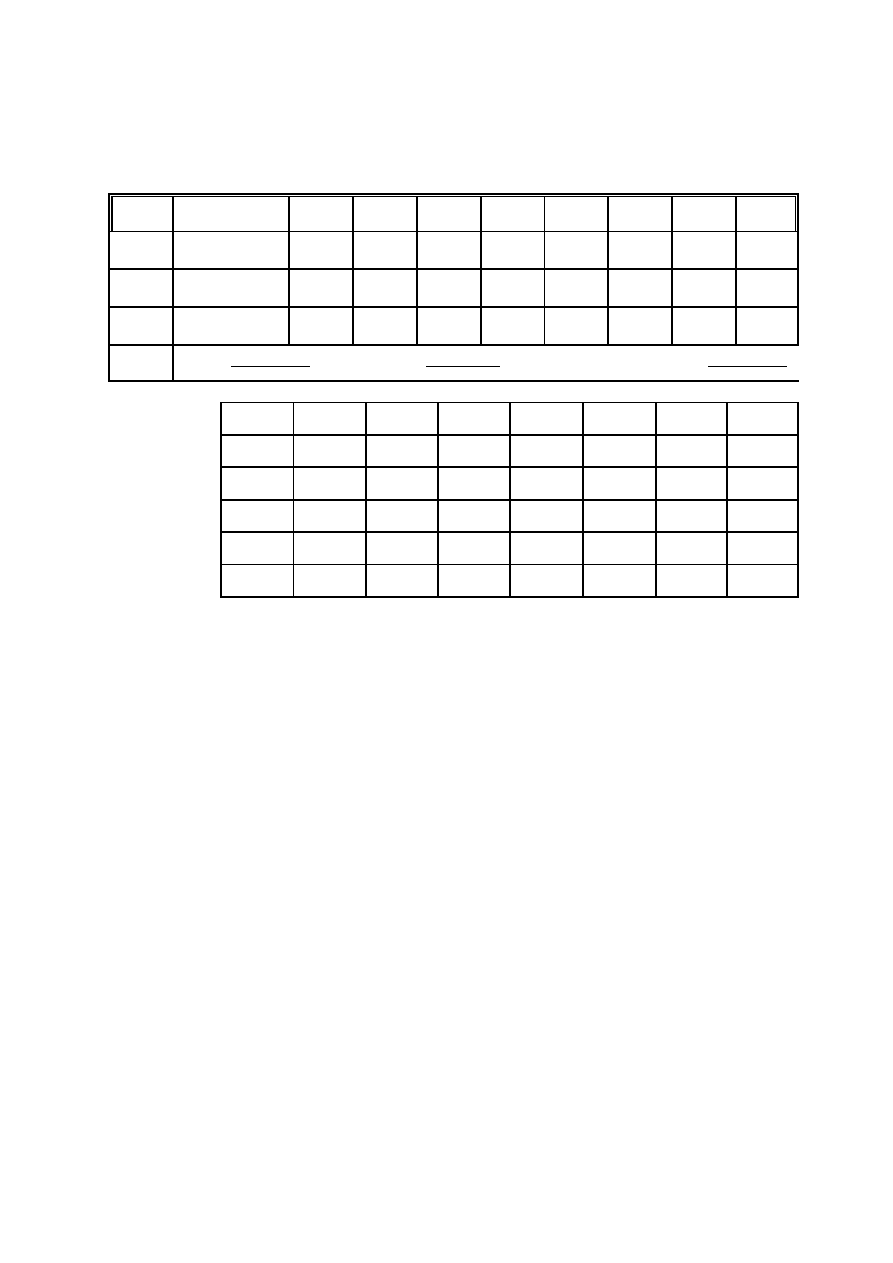
Table 3: Form for calculating and plotting the righting lever curve
(the GZ-axis may be expanded if necessary)
2.6.6
One calculated example should be provided together with explanatory comments. A note should
be given that in calculating a loading condition, at least one (or pair of) fuel and fresh water tank should
be considered slack.
2.6.7
If the ship is equipped with an approved installation for performing in-service inclining tests, a
reference note should be given to the operations manual of this equipment, or, if deemed appropriate,
comprehensive guidance placed in this subsection.
If, on request by the owner, the loading and stability manual is to contain additional technical information
for supporting a draught survey or other stability management issues, appropriate guidance and calculated
examples should be given in this subsection. The Guidelines on the management of ship's stability, to be
developed by the Organization, should be taken into account, if appropriate.
Section 3 - Technical information (Category 1 and 2)
3.1
Capacity plan
3.1.1
This subsection should contain a scaled drawing showing the layout of cargo spaces, tanks, stores,
machinery spaces and crew/passenger accommodation. Cargo spaces and tanks should be suitably
identified by purpose, names and/or numbers consistent with other information in this manual.

MSC/Circ.920
ANNEX
Page 13
I:\CIRC\MSC\920.WPD
3.1.2
The above plan should, in addition, present:
.1
reference planes and the rise of keel, where applicable;
.2
frames, frame spacing and numbering; and
.3
location of draught marks forward, mid and aft.
3.1.3
The reference planes should preferably be at the:
.1
aft perpendicular for the longitudinal coordinates;
.2
centre line for the transverse coordinates; and
.3
base line for the vertical coordinates.
3.1.4
The above plan should, in addition, present a diagram of the load line marks showing:
.1
position of the deck line relative to the ship;
.2
draught to the summer load waterline;
.3
draught to the summer timber load waterline;
.4
corresponding freeboards; and
.5
deadweight scale.
3.2
Cargo space information
3.2.1
This subsection should present information on cargo spaces in the form of a suitable table
containing:
.1
name and/or number of space;
.2
frame numbers at forward and aft end of space;
.3
volume at 100% filling; and
.4
longitudinal, transverse and vertical co-ordinates of the centre of volume with regard to the
reference planes.
3.2.2
On break-bulk ships, additionally, the permissible surface load per area for the particular deck or
tanktop should be given in t/m . The volume of spaces may be given separately for bale cargo and for
2
grain, if appropriate.
3.2.3
On bulk carriers, the permissible total mass of cargo in the particular space should be given.

MSC/Circ.920
ANNEX
Page 14
I:\CIRC\MSC\920.WPD
3.2.4
On tankers, additionally, the volume at 98% filling and the moment of inertia of the free surface
at 98% filling should be given.
3.2.5
On ships equipped for the carriage of containers, a detailed container stowage plan should be
provided using an accepted numbering system and presenting the longitudinal, transverse and vertical
co-ordinates of the assumed centres of mass of containers. The vertical co-ordinates should refer to a
centre of mass at 50% of container height of ISO containers of 8'06" height. If the ship is intended to carry
other types of containers, their appropriate height should be used.
Any reduction of vertical co-ordinates with regard to the assumption of centre of mass should be indicated.
Maximum stack masses and maximum stack heights of containers may be included in this information.
3.2.6
On ro-ro ships, the stowage lanes should be suitably subdivided for identifying longitudinal
co-ordinates of stowage positions. The vertical co-ordinates should refer to 2 m above the deck level,
unless the cargo in a specific trade requires a different value.
3.3
Tank space information
3.3.1
This subsection should present information on tank spaces intended for fuel, stores, feed water,
domestic water, process liquids and liquid waste in the form of suitable tables showing:
.1
name and/or number of tank and designated contents;
.2
frame numbers at forward and aft end of tank;
.3
volume at 100% filling;
.4
density of the liquid (
D
);
.5
mass at 100% filling;
.6
longitudinal, transverse and vertical co-ordinate of centre of volume; and
.7
maximum value of moment of free surface (i .
D
).
B
3.3.2
Separate summary tables may be included for:
.1
full consumables with waste reception tanks empty and full free surfaces for one (or pair
of) fuel and fresh water tank;
.2
approximately half capacity of consumables and waste reception tanks;
.3
minimal arrival capacity of consumables with waste reception tanks full; and
.4
typical ballast configurations required for substantial deck cargoes or ships with sensible
stability.
The results of these summary tables should be used in the appropriate loading conditions in this manual.
MSC/Circ.920
ANNEX
Page 15
I:\CIRC\MSC\920.WPD
3.3.3
For deep tanks, side tanks, peak tanks and other tanks with unusual shape, holding more than 0.1%
of the ship's summer displacement, individual sounding tables should be provided presenting tank
identification, contents, density and:
.1
sounding in steps of 0.1 m or less;
.2
contents volume at given sounding;
.3
longitudinal, transverse and vertical co-ordinate of centre of contents; and
.4
moment of free surface (i .
D
).
B
3.3.4
For deep tanks, including cargo tanks, with a width of 0.6 . B or more, separate individual tables
should be provided presenting tank identification, contents, density and:
.1
sounding in steps of 0.1 m or less;
.2
contents volume at given sounding; and
.3
volumetric heeling moment of given volume at heeling angles from 10° to 80° at intervals
of 10°.
The heeling moments of liquid volumes should be computed in accordance with 3.3 of the Intact Stability
Code, as amended.
3.4
Hydrostatic particulars
3.4.1
Hydrostatic particulars should be presented for the ship on even keel or design trim without
deflection in a table against draught to the bottom of keel over a range from light ship to 115% of the
maximum draught or to the depth of hull, whichever is less.
The tabulated intervals should be not greater than 5 cm. Values should be rounded to decimal places
shown below.
3.4.2
The tabulated values should include:
T
KC
m
DISV
m
3
DISM
t
TPC
t/cm
KM
m
MTM
tm/m
XB
m
XF
m
.
.
6.05
.
.
.
.
8677,3
.
.
.
.
8894.3
.
.
.
.
18.00
.
.
.
.
9.038
.
.
.
.
10783
.
.
.
.
59.48
.
.
.
.
58.78
.
.
Instead of MTM, the values of MTC may be used (see subsection 2.2). The position of reference planes
should be confirmed for KM, XB and XF.
MSC/Circ.920
ANNEX
Page 16
I:\CIRC\MSC\920.WPD
3.4.3
Where the operation of the ship results in loading conditions having significant trim, i.e. trim
exceeding 0.01 . L, additional hydrostatic particulars should be prepared for a suitable range of trim.
This applies in particular to the z-coordinate of the metacentre KM which should be given for ships where
stability may become critical due to cargo stowage pattern. The following presentations should be used,
if appropriate:
T
KC
m
KM for trimmed conditions (m)
t = - 3 m
t = - 2 m
t = - 1 m
t = 0 m
t = 1 m
t = 2 m
.
.
8.20 m
.
.
.
.
9.523
.
.
.
.
9.422
.
.
.
.
9.332
.
.
.
.
9.256
.
.
.
.
9.217
.
.
.
.
9.162
.
.
3.4.4
Cross curve data should be provided for the same conditions as lined out under 3.4.1 for heeling
angles from 10° to 80° at 10° intervals. Closer spacing or particular angles may be required for certain
ships or special purposes, e.g. grain stability.
Where the operating trim or the form and arrangement of the ship are such that change in trim has an
appreciable effect on righting arms, additional cross curve tables should be included for a suitable range
of trim. A statement should be appended to the table indicating the erections and/or timber deck loads
which are included in the cross curve values.
T
KC
m
LK 10°
m
LK 20°
m
LK 30°
m
LK 40°
m
LK 50°
m
LK 60°
m
LK 70°
m
LK 80°
m
.
.
6.60
.
.
.
.
1.578
.
.
.
.
3.207
.
.
.
.
4.773
.
.
.
.
6.067
.
.
.
.
7.030
.
.
.
.
7.560
.
.
.
.
7.748
.
.
.
.
7.650
.
.
3.5
Lightship particulars
3.5.1
This subsection should present data resulting from the inclining experiment and deadweight survey:
.1
lightship mass;
.2
longitudinal, transverse and vertical centre of mass including the relevant reference planes;
.3
calculated and measured deflection of the hull, if appropriate;
.4
place and date of the inclining experiment; and
.5
name of organization responsible for the approval of the above results.

MSC/Circ.920
ANNEX
Page 17
I:\CIRC\MSC\920.WPD
3.5.2
If dispensation from carrying out an inclining experiment has been given, the name of the authority
and the reasons should be stated including details of the reference ship or ships from where the data have
been concluded.
3.5.3
If permanent ballast is contained in the light ship mass, a description of such ballast should be
included giving the material, its mass and distribution to the common reference planes. A sketch showing
the distribution of such ballast should be included.
3.5.4
If a rolling period test is required by the Administration details of the result should be given.
3.6
Load line particulars
3.6.1
This subsection should contain a statement giving the type of load line assigned (i.e. type A, B, etc.)
and a table showing for the appropriate load line marks (winter, summer, tropical, etc.) the values of:
.1
draught to bottom of keel;
.2
freeboard;
.3
displacement mass in seawater (
D
= 1.025 t/m ); and
3
.4
deadweight.
3.6.2
If the assessment of freeboard is based on a design trim other than zero, this should be stated.
Furthermore, the maximum permissible draught at the forward perpendicular if necessary for bow height
consideration should be stated.
3.6.3
Minimum draught forward and minimum draught aft should be stated with regard to ship handling
in heavy weather. This information may be regarded as category 1B information.
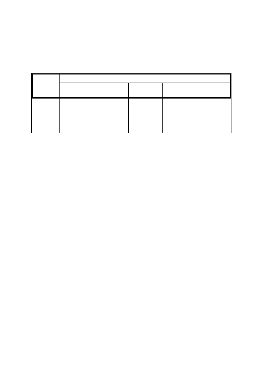
3.7
Stability limits
3.7.1
This subsection should contain a precalculated table from which the master can determine whether
the stability of the ship is acceptable for a given loading condition under the governing stability criteria.
This information should preferably show the maximum allowable height of the loaded ship's centre of
gravity KG , i.e. appropriately corrected for free surfaces, against the reference keel draught T .
c
KC
If the maximum allowable KG depends on specific parameters, e.g. height of deck cargo, layers of
c
containers on deck, trim, or other conditions of service, the table or tables should provide for any suitable
combination of limiting KG values. If, in particular the trim is considered not to influence the limiting
c
KG values, this should be clearly stated.
c
MSC/Circ.920
ANNEX
Page 18
I:\CIRC\MSC\920.WPD
The range of data should extend from the lightest anticipated seagoing draught to the minimum freeboard
assigned. An example for such table is given below:
T
KC
Maximum permissible KG for any operating trim (m)
c
m
no containers
on deck
1 tier deck
containers
2 tier deck
containers
3 tier deck
containers
4 tier deck
containers
.
.
5.20
.
.
.
.
9.05
.
.
.
.
9.05
.
.
.
.
9.05
.
.
.
.
8.99
.
.
.
.
8.85
.
.
3.7.2
The alternative presentation of minimum values of metacentric height, corrected for free surfaces,
as a determining parameter of compliance with stability criteria should not be used for ships where stability
management is likely to incorporate the in-service inclining test. The presentation, however, of maximum
KG values as limiting parameters will prompt the user to obtain the actual KG from the measured GM .
c
c
c
In the case of notable trim, the user should utilize KM for trimmed condition.
3.7.3
The angle of down flooding, as defined in paragraph 3.2.2.1.5 of the Intact Stability Code, should
be tabulated against the reference keel draught T for the ship on even keel or design trim over the range
KC
defined under 3.7.1. The critical openings should be identified together with their co-ordinates to the
common reference planes.
3.7.4
A separate set of information should, in the form of suitable tables and/or diagrams, provide the
appropriate damage stability criteria. The form of presentation should be similar to the presentation of the
intact stability criteria as far as practicable.
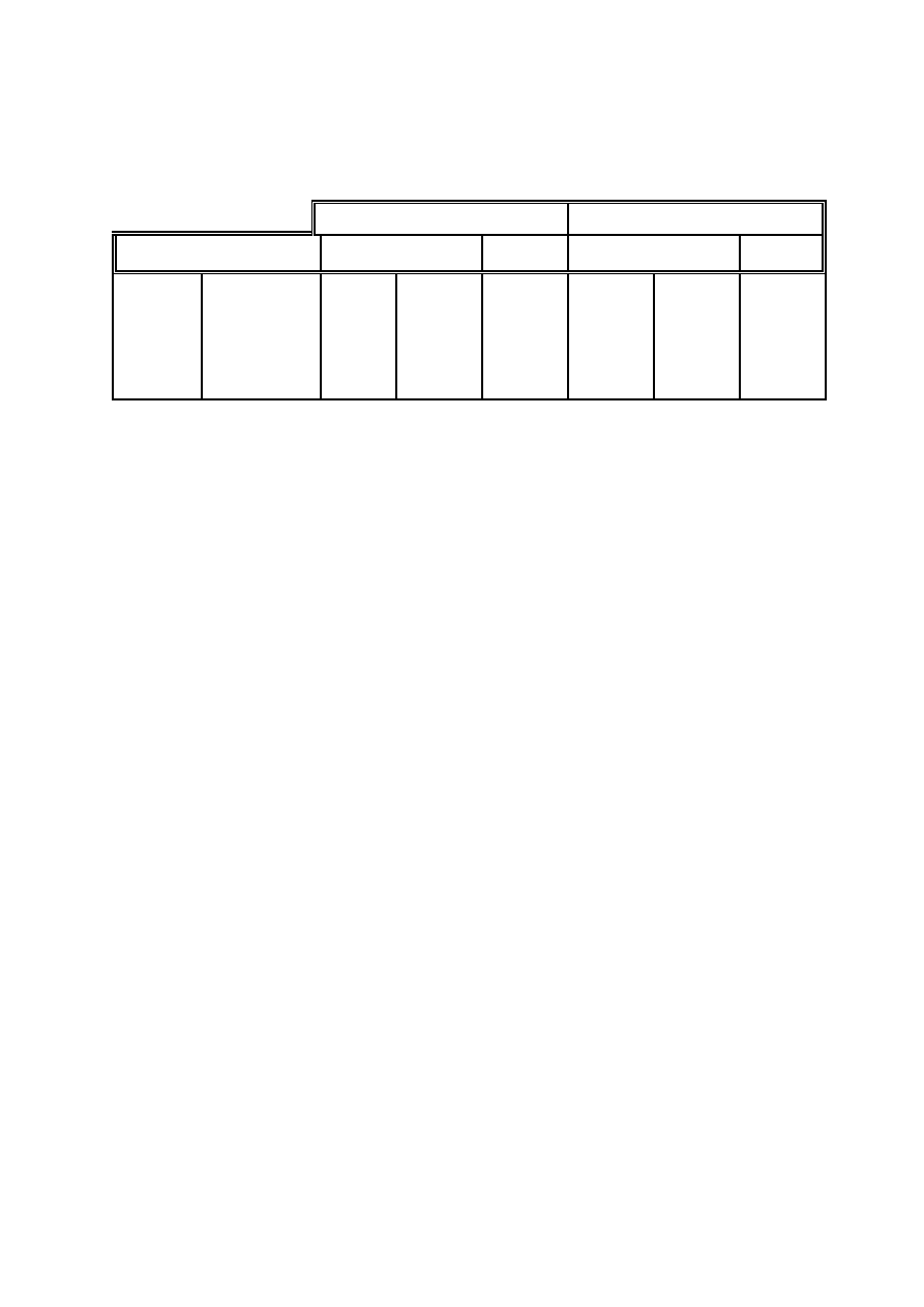
3.8
Longitudinal strength criteria
3.8.1
This subsection should contain, in a suitable table for selected longitudinal positions, i.e. frames
or bulkheads the:
.1
frame number and longitudinal co-ordinate;
.2
maximum permissible shearforces, positive and negative, for operation in port and at sea;
and
.3
maximum permissible bending moments, positive and negative, for operation in port and
at sea.
MSC/Circ.920
ANNEX
Page 19
I:\CIRC\MSC\920.WPD
Shear force limit (kN)
Bending moment limit (kNm)
Frame
x-co-ordinate
at sea
in port
at sea
in port
.
.
64
.
.
.
.
44,2 m
.
.
.
.
21050
.
.
.
.
- 20750
.
.
.
.
± 25350
.
.
.
.
292850
.
.
.
.
- 240400
.
.
.
.
± 465350
.
.
If those limiting values depend on specific parameters, e.g., homogeneous or alternating cargo distribution,
draught, or other conditions of service, additional tables should be provided as appropriate.
3.8.2
A separate table for pre-estimating the ship's deflection from bending moments in the full sections
of the ship may be provided in this subsection. This information should reflect any constant deflection as
may be identified during the initial inclining experiment and deadweight survey, if required. The maximum
allowable deflection (hog or sag) in port and at sea should be specified. The information addressed to in
this paragraph may be considered as category 1B information.
3.8.3
Maximum allowable torsional moments should be provided in a table as described under 3.8.1 for
ships which are sensible to torsion due to their construction and cargo stowage practice.
3.9
Other operational restrictions
3.9.1
This subsection should contain information and/or reference to other operational restrictions related
to the loading and the operation of the ship. This may include:
.1
trim and/or deck-stowage restrictions due to SOLAS-sightlines;
.2
restrictions to high initial stability with regard to securing of deck cargoes, in particular
containers (refer to the Cargo Securing Manual);
.3
stability and trim requirements with regard to damage control (refer to the Guidelines for
damage control plans, MSC/Circ.919);
.4
operating restrictions with regard to ship handling in heavy weather (refer to the Guidance
to the master for avoiding dangerous situations in following and quartering seas
(MSC/Circ.707)); and
.5
maximum permissible draught (scantling draught) corresponding to structural strength of
the ship.
3.9.2
The information in this subsection may be transferred to subsection 2.4 (Operation of the ship), if
deemed useful.

MSC/Circ.920
ANNEX
Page 20
I:\CIRC\MSC\920.WPD
Section 4 - Reference information (Category 3)
This section should contain information which is not necessary for the operation of the ship but deemed
useful as reference for the master and/or necessary for the approval by the Administration.
4.1
Inclining experiment report
The inclining test report presented in this subsection should be detailed to the satisfaction of the
Administration.
4.2
Intact stability criteria
This subsection should contain the relevant text of the intact stability criteria assigned to the ship by the flag
State Administration and which are the basis for stability limits presented in subsection 3.7.
4.3
Other information
This subsection should contain other reference information deemed useful by the Administration or owners.
________
Wyszukiwarka
Podobne podstrony:
4 Steyr Operation and Maintenance Manual 8th edition Feb 08
Glow Worm installation and service manual Hideaway 70CF UIS
Glow Worm installation and service manual Ultimate 50CF UIS
Glow Worm installation and service manual Ultimate 60CF UIS
Microstructures and stability of retained austenite in TRIP steels
Glow Worm installation and service manual Glow micron 60
Mauser 98k Model 48 Rifle (8mm) Manual
Glow Worm installation and service manual Glow micron 40
Glow Worm installation and service manual Hideaway 80BF UIS
Glow Worm installation and service manual Hideaway 50CF
Glow Worm installation and service manual Energy Saver 60 UI
Glow Worm installation and service manual Hideaway 120BF UIS
Glow Worm installation and service manual Hideaway 120CF UIS
Glow Worm installation and service manual 45 BBU 2
Glow Worm installation and service manual Ultimate 40CF UIS
Glow Worm installation and service manual Glow micron 70
dns client and cache manual
więcej podobnych podstron