www.steyr-motors.com
STEYR MOTORS GmbH
Im Stadtgut B1, A-4407 Steyr-Gleink, AUSTRIA
STEYR MARINE ENGINES
OPERATION,
MAINTENANCE AND
WARRANTY MANUAL
P/N Z001022/0 8
th
Edition February 2008
4 CYLINDERS
+ 6 CYLINDERS
4 CYLINDERS
+ 6 CYLINDERS

WELCOME ABOARD
Congratulations on your decision of choosing a STEYR marine engine
for your boat, and we hope you will enjoy it.
STEYR MOTORS GmbH has developed a high-speed diesel engine
with modulated high-pressure fuel injection specifically for the marine
environment. STEYR’s marine engines are designed to be adapted to
various propulsion systems.
To come up to your expectations, please study thoroughly this manual
for your new STEYR marine engine to get sufficient information
on its operation and handling and to permit an optimal use of the
various built-in functions.
With kind regards,
STEYR MOTORS GmbH
STEYR MOTORS GmbH
After Sales Service
Im Stadtgut B1
4407 Steyr, Austria
www.steyr-motors.com
8
th
Edition, February 2008
P/N Z001022/0
YOUR STEYR MARINE DEALER
3
4
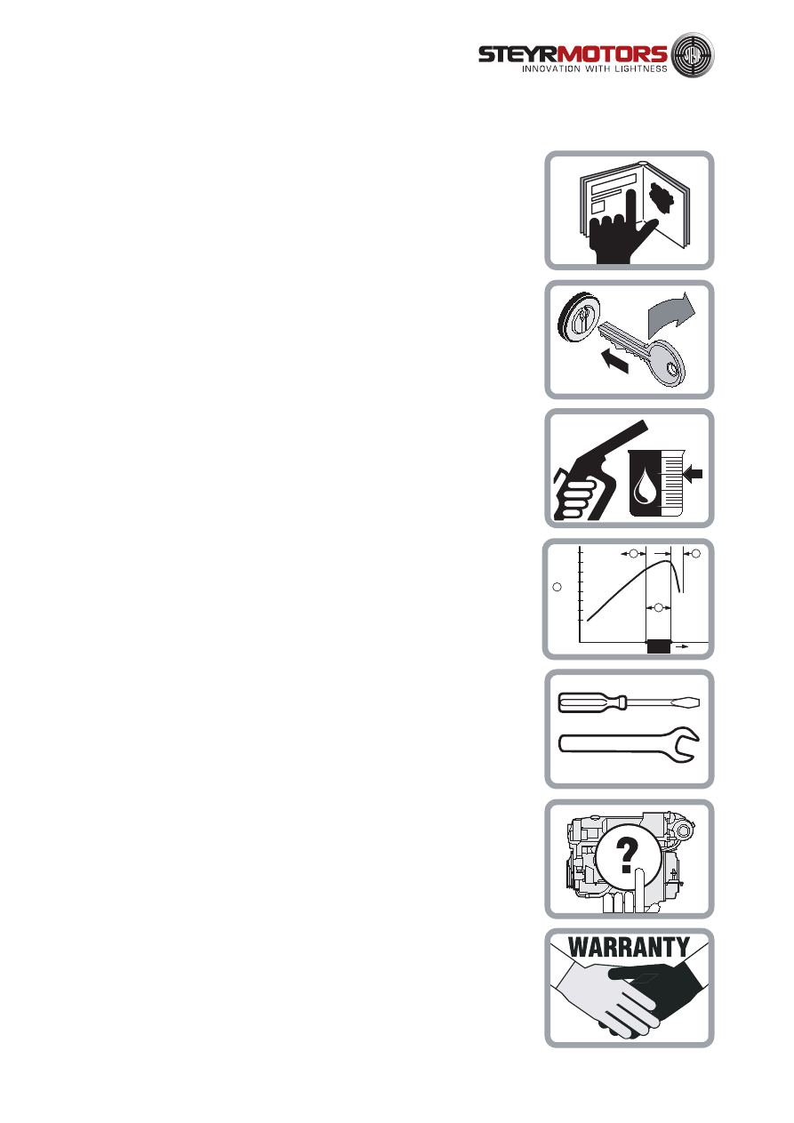
How to use this manual
Table of Contents
PAGE 13 - 38
START-UP AND FUNCTIONS
This section contains brief instruction, function description and normal operation, as
well as correct start-up and handling of STEYR marine engines.
PAGE 5 - 12
GENERAL PART
This section contains user instructions and general notes on safety for STEYR
marine engines.
PAGE 39 - 42
FUEL AND LUBRICANTS
This section defines the requirements as to fuel and lubricants for STEYR marine
engines.
PAGE 43 - 54
TECHNICAL DATA
This section contains technical data and product description of STEYR marine
engines.
PAGE 55 - 82
MAINTENANCE, TROUBLE SHOOTING
This section contains instructions for required maintenance and notes on the
elimination of possible troubles on your STEYR marine engine.
PAGE 83 - 98
DEALER´S ACTIVITIES
This section contains instructions for installation acceptance tests, propeller selection,
removal from service, start-up after storage, adequate disposal and dealer´s test list.
PAGE 99 - 108
WARRANTY, GENERAL DISTRIBUTORS
This section contains warranty conditions (services and obligations) for owners and
manufacturers of STEYR marine engines.
full load
speedrange
100%
90%
80%
70%
60%
50%
40%
30%
B
C
D
RPM
A
OUTPUT POWER

5
GENERAL PART
General .......................................................................................................6
Product References, Illustrations and Specifications................................. 7
Insurance ................................................................................................... 7
Stolen Unit ................................................................................................. 7
Owner Identification Card .......................................................................... 7
Installation Acceptance Records ................................................................ 8
Dealer Service ........................................................................................... 8
Illustration Symbols ................................................................................... 8
Repair Service ........................................................................................... 9
Replacement Parts .................................................................................... 9
Before Casting Off ..................................................................................... 9
Engine Submersion ................................................................................. 10
Bottom Painting ....................................................................................... 10
Boat Bottom .............................................................................................. 10
Boating Responsibilities ........................................................................... 11
Safety ....................................................................................................... 11
Symbols ................................................................................................... 12
6
This
MANUAL
is published by STEYR MOTORS GmbH with the main intention -
to provide information in form of technical data and know-how based on our experience in the marine diesel engine
business, which will enable you, after thorough study to operate and service the engines on your boat, ensuring
their operating safety, reliability and long service life.
CE conformity:
Under regular maintenance, as described in the chapter "Maintenance and Trouble Shooting", the exhaust gas
emission levels adhere to the limits stipulated, for pleasure boat operation, throughout the life time of the engine.
All warranty claims to be addressed to your local STEYR Marine Dealer.
(We have to rely on your assistance however) For continuous improvement with regard to form and contents of the
information required.
Your comments on the following questions would be much appreciated -
- Which descriptions or terms are not understandable?
- Which enlargements or complements do you suggest ?
- Where did content-related mistakes slip in ?
Please address your comments and ideas to your STEYR - Marine Dealer.
< 3700 rpm.
< 2600 rpm.
< 4000 rpm.
Since this manual covers the whole family of STEYR marine engines, differing sections are marked as follows:
1.)
whole page applies to all engines
2.)
whole page applies to specified engine types only
3.)
whole page applies in principle for
all engine types,
but different data, e.g. technical
data, is marked.
M0144K33
M0144K33
M0166K28
M0236K42
GENERAL

7
Product References, Illustrations and Specifications
When reference is made in this manual to a brand name, number, product or specific tool, an equivalent product may
be used in place of the product referred to unless specifically stated otherwise. Equivalent products which are used must
meet all current US Coast Guard Safety Regulations and ABYC standards to avoid hazards.
Other countries may apply additional internal regulation. Please follow their advices appropriately.
Austria:
Bundesamt für Schiffahrt
Sweden:
Navigation Office
Finland:
Navigation Office
Norway:
DNV = Det Norske Veritas
USA:
USCG = United States Coast Guard
USA:
ABYC = American Boat Yacht Council
USA:
NMMA = National Marine Manufacturers Association
England:
LR = Lloyds Register of Shipping
France:
BV = Bureau Veritas
Germany:
GL = GERMANISER Lloyd
Italy:
RINA = Registro Italiano Navale
All information, illustrations and specifications contained in this manual are based on the latest product information
available at the time of printing. STEYR MOTORS GmbH reserves the right to make changes at any time, without
notice, to specifications and models and also to discontinue models, as well as the right to change
specifications or parts at any time without incurring any obligation to equip same on models manufactured
prior to date of such change.
Continual accuracy of this manual cannot be guaranteed.
All illustrations used in this manual may not depict actual models or equipment and are intended as representative views
for reference only.
Insurance
Insurance on your STEYR Marine Engine and boat should be obtained as soon as practical for protection against
loss by fire, theft, etc. Consult your local insurance agent.
Stolen Unit
The model and serial numbers on your engine are important for you. As to the location of these important numbers, refer
to Model and Serial Numbers in this section.
Record each of these numbers in the spaces provided at the end of this manual and on a separate sheet. Store the
separate sheet in a safe place other than your boat.
In case of theft, report the model and serial numbers to your local authorities and your insurance agent.
Owner Identification Card
When you purchases your boat, your dealer was obliged to issue an owner identification card for your STEYR Marine
Engine.
This owner identification card gives proof and is to be submitted in case of warranty claims.
8
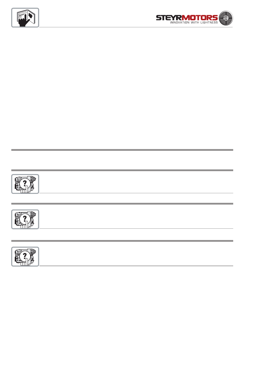
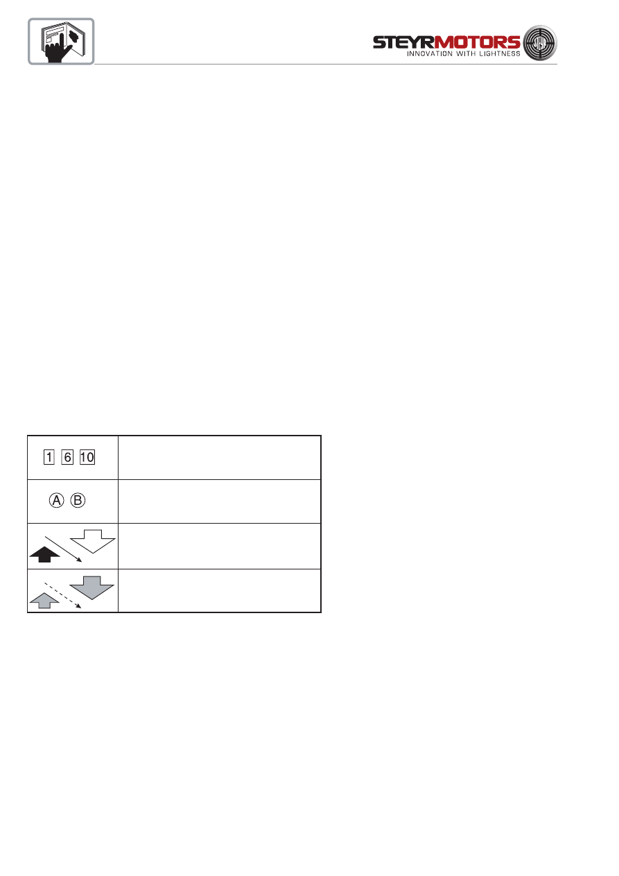
Refer to the photograph or drawing
described in that paragraph.
Refer to specific items or features
described in the text and illustrated
on the photograph.
Refer to the general subject of the text.
Refer to an item or feature not
clearly visible on the photograph.
Installation and pre-delivery inspection log
Your STEYR Marine dealer is also obliged to complete the Installation Acceptance Records (Chapter "DEALER´S
ACTIVITIES"). Required tests and measurements are to be carried out accordingly.
A copy of the Installation Acceptance Records is to be forwarded to STEYR MOTORS GmbH.
Dealer Service - Maintenance
NOTE:
Please do not forget to have confirmed in your manual that the installation acceptance test
and the service have been carried out in accordance with the installation acceptance records.
This is also an opportunity to clarify with your STEYR marine dealer possible questions arisen during the first running
hours on your boat, and to establish a service- and maintenance routine.
Services will be performed by STEYR Marine Dealers at local rates.
Costs for service material to be born by the owner.
Illustration Symbols

9
Repair Service
All repair works on your STEYR marine engine should be carried out by a licensed STEYR Marine Dealer with his
professional knowledge, trained staff and special-purpose tools to solve all occuring problems. Preferably, all works
on your STEYR marine engine should be carried out by the STEYR Marine Dealer that sold the equipment to you -
he knows you and the equipment.
If problems occur during a trip, bring your STEYR marine engine to the next STEYR Marine Dealer. As to information
on dealer addresses see page 3 with phone- and fax numbers of your STEYR Marine Dealer.
Replacement Parts
Your STEYR Marine Engine was designed to operate in a marine environment.
* For long periods at high RPM only use STEYR Marine matched replacement parts.
Before Casting Off
Check the weather report, wind and water conditions. Tell someone where you are going to and when you expect to
arrive or return.
Recommended Minimum
On-Board Tools
large screwdriver
wrench set
small screwdriver
12-volt pilot lamp
cross-point screwdriver
flashlight
tongs
insulating tape
long nose pliers
wrench for socket head cap screws
Recommended Minimum
On-Board Spare Parts
propeller and small parts for propeller mounting
fuses
fuel filter
bulbs
impeller for raw water pump
leakage screws
These lists represent a suggested MINIMUM, and are not intended to cover all boats or possible boating conditions.

10
Engine Submersion
Save engine from water as quickly as possible and contact your local STEYR Marine dealer for service.
It is imperative that your dealer removes all water from the engine and immediately relubricates all internal parts.
Electrical devices must be replaced. Delay in completing these actions may allow extensive engine damage.
Frequently check engine compartment for excessive water accumulation; water depth in bilge should be kept well below
flywheel housing.
Bottom Painting
If your boat is in water where marine growth is a problem, the use of an antifouling paint will reduce the growth rate.
*Tin base antifouling paint (TBTA or TBTF) is recommended where its use is permitted.
*Copper base antifouling paint may be used, but will require more frequent inspection and replacement of
sacrificial anodes. DO NOT PAINT any part of the vertical drive with copper base antifouling paint.
NOTE:
Painting the vertical drive with copper base paint will accelerate galvanic corrosion.
*
Vinyl-butyl base antifouling paint is a recommended alternative.
*
DO NOT USE any graphite base antifouling paint.
NOTE:
Never paint anti-corrosion anodes, or their effectiveness will be lost.
See your STEYR Marine contract partner for an antifouling paint that is suitable for your area.
Boat Bottom
The condition of the boat bottom can affect your boat's performance. Marine growth, present in fresh water as well as
salt water, will reduce boat speed. A boat bottom with evidence of marine growth causes a reduction in top speed of
20 percent or more. Periodically clean the bottom of your boat following the manufacturer's recommendations.
11
Boating Responsibilities
As a boat owner, you have certain responsibilities to others. Be sure that all operators read this manual.
You are legally responsible for all occupants of your boat. Instruct at least one of your passengers in the basic
fundamentals of handling your boat in case of an emergency. Show all hands the location of emergency equipment and
how to use it. You are required by law to have one US Coast Guard approved life jacket for each person aboard, plus
one approved throwable device for man overboard protection.
Learn the waterway rules of the locality in which you are going to operate your boat. Navigable waterways are controlled
by Federal regulations while inland lakes are controlled by local jurisdictions. Obey these regulations to protect yourself,
your passengers and fellow boating enthusiasts.
Thoroughly familiarize yourself with weather station warning system signals and waterway traffic signs.
Contact your local Coast Guard station and take advantage of their seasonal boat inspections and training courses.
Safety
This manual contains certain information related to the personal safety of you the operator, your passengers and
bystanders.
The Safety symbol ATTENTION: appears next to important information to prevent you and others from being
hurt.
The Note symbol NOTE: appears next to important information to keep machinery from being damaged.
Observe all notes and safety warnings contained in this manual.
WARNING
CALIFORNIA: PROPOSITION 65 WARNING
Diesel engine exhaust and some of its constituents are known to the state of California to cause cancer, birth defects,
and other reproductive harm.
12
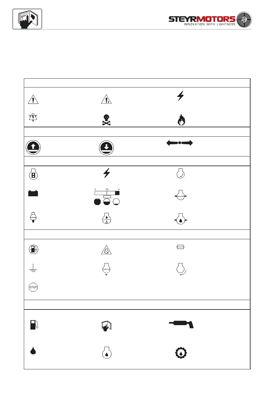
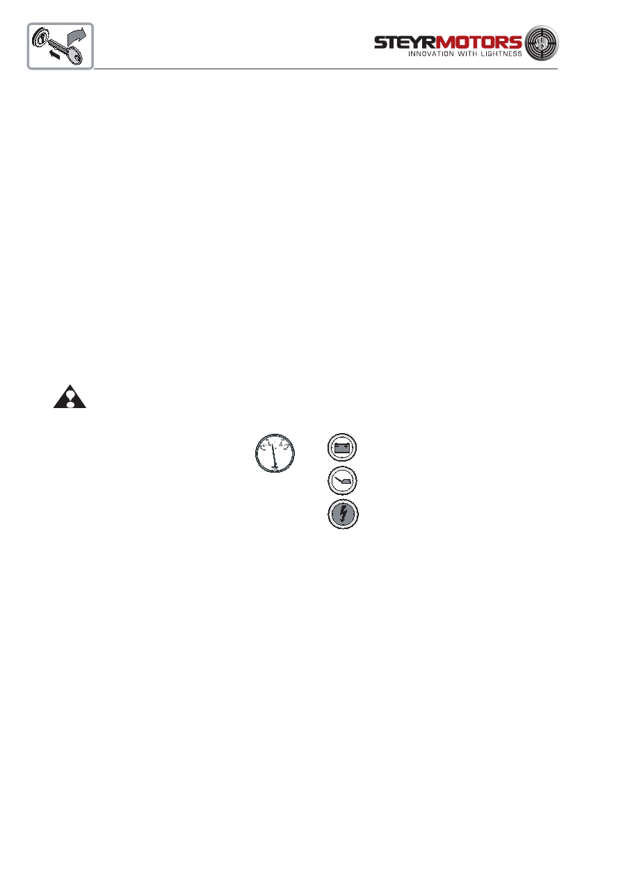
Symbols
Certain symbols or combinations of symbols may appear on your STEYR Marine Engine or on its accessories. It is
very important that you understand their meaning or purpose. If any symbol is not clearly understood, see your DEALER.
"Safety Warning" Symbols
"Position Indicator" Symbols
"Condition" Symbols
"Functional Description" Symbols
"Instructional" Symbols
Means risk of SERIOUS injury is present.
Follow instructions in the Operation,
Maintenance & Warranty Manual
before using motor or
accsessory.
Indicates that contents are under
pressure.
Indicates upward movement.
Example: While boat is at planing speed,
activating trim switch to raise the bow
of the boat.
Means place shift control in NEUTRAL
before starting motor. Follow instructions
in Operation, Maintenance & Warranty
Manual before starting
motor.
Identifies poisonous material.
Indicates that ELECTRICITY of more
than 50 volts is present.
Indicates a potential fire hazard.
Indicates gear shift control positions:
FORWARD, NEUTRAL and
REVERSE
Indentifies the meter which indicates
accumulative running hours of engine.
Identifies battery or a meter wich
indicates status of battery-
generator charging system.
Identifies the meter which indicates
engine coolant temperature.
Identifies the meter which indicates
battery voltage or amperage.
Indicates the amount of liquid
in tank.
FILTER: Identifies a device which
removes contaminants from
engine´s oil system.
Identifies the meter which indicates
engine speed expressed in
revolutions per minute.
Indentifies the meter which indicates
engine coolant pressure.
Identifies the meter which indicates
the pressure of engine´s lubricating
system.
FILTER: Identifies a device which
removes contaminants from fuel.
Identifies the negative ground or
negative voltage connection.
Identifies the STOP SWITCH.
It may also identify STOP position
of the throttle control.
Identifies the EMERGENCY IGNITION
CUT-OFF SWITCH.
Emergency engine stop.
Identifies engine drain plugs and
fittings.
FUSE: Identifies a device which
protects the electrical system from
overload.
Identifies the operating device for
starting the motor.
Indicates FUEL is to be used or
FUEL is present.
Indicates OIL is to be used or
OIL is present.
Means read your Operation,
Maintenance & Warranty Manual
before operating the product. It
contains information or instructions
vital for operation of product.
ENGINE OIL FILL: Location for
introduction of oil into the engine.
Indicates areas to be lubricated.
Indicates lubricating oil used in
transmissions.
Indicates downward movement.
Example: While boat is at planing
speed, activating trim switch to lower
the bow of the boat.
or

13
START-UP AND FUNCTIONS
Before starting .......................................................................................... 15
Starting the engine ................................................................................... 16
Stopping the engine ................................................................................. 16
Starting the engine (for SOLAS only) ....................................................... 17
Stopping the engine (for SOLAS only) ..................................................... 17
Engine Break-In procedure ....................................................................... 18
Operation after Break-In ........................................................................... 20
Shifting ..................................................................................................... 21
Remote control operating instructions ...................................................... 22
How to shift and control speed ................................................................. 23
Fuel economy ........................................................................................... 23
Gear box ................................................................................................... 23
High altitude operation.............................................................................. 23
Instrument panel ...................................................................................... 24
Instrument indication during normal operation .......................................... 25
Instrument panel (for SOLAS only).......................................................... 26
Instrument indication during normal operation (only for SOLAS) ............. 27
Emergency stop switch ........................................................................... 28
Emergency stop switch (for SOLAS only) ............................................... 28
Warning lights and audible alarm ............................................................ 29

14
START-UP AND FUNCTIONS
Electronic Engine Control Unit (ECU) .......................................................30
Diagnostic system .................................................................................... 31
Counter-rotation models .......................................................................... 32
Optional propellers .................................................................................. 32
Propeller torque ....................................................................................... 33
Propeller care .......................................................................................... 33
Water jet ................................................................................................... 33
Operating procedure for freezing temperatures........................................ 33
Operation in salt water ............................................................................. 33
Fuel pump ................................................................................................ 34
Fuel system checks ..................................................................................34
Fuel contamination ...................................................................................34
Cooling system (Function description) ..................................................... 35
Electrical equipment .................................................................................36
Alternator .................................................................................................. 36
Battery ......................................................................................................36
Circuit breakers ........................................................................................ 37
Inversion switch (for Solas only) ............................................................... 38
Interrupt crankshaft housing ventilation (for Solas only) ........................... 38
Instrument panel (for Solas only).............................................................. 38
Dry operation (for Solas only) ................................................................... 38

15
Before Starting
Familiarize yourself with the handling of the boat, in particular how to use transmission, and then proceed as follows:
1.
Check the bilge for excessive water accumulation. Always keep the bilge clean and dry. Never allow the water
level in the engine compartment to exceed the bottom of the oil pan. If water accumulation is unavoidable, install
a bilge pump with an automatic control switch.
NOTE:
The water level in the boat's engine compartment will increase when the boat is operated at a high
incline before planing speed is reached. Excessive water accumulation in the engine compartment/
bilge may cause engine failures.
2.
Open the raw water intake valve.
NOTE:
Operate the engine only while the raw water supply is assured or the cooling system is equipped
with a flushing device. The raw water pump will be damaged and/or the engine will overheat if
operated without cooling water.
3.
Open the fuel stop valve.
NOTE:
Only start the engine when a bubble-free fuel supply is guaranteed. Prior to first start-up of the
engine (after installation, after storage etc.), purge the fuel system by "ignition ON" for 6 x 10 sec.
4.
Check the operating resources
* coolant
* oil
* hydraulic oil
* transmission oil
* fuel
5.
Control of electric
* Charge and charge state of battery.
16
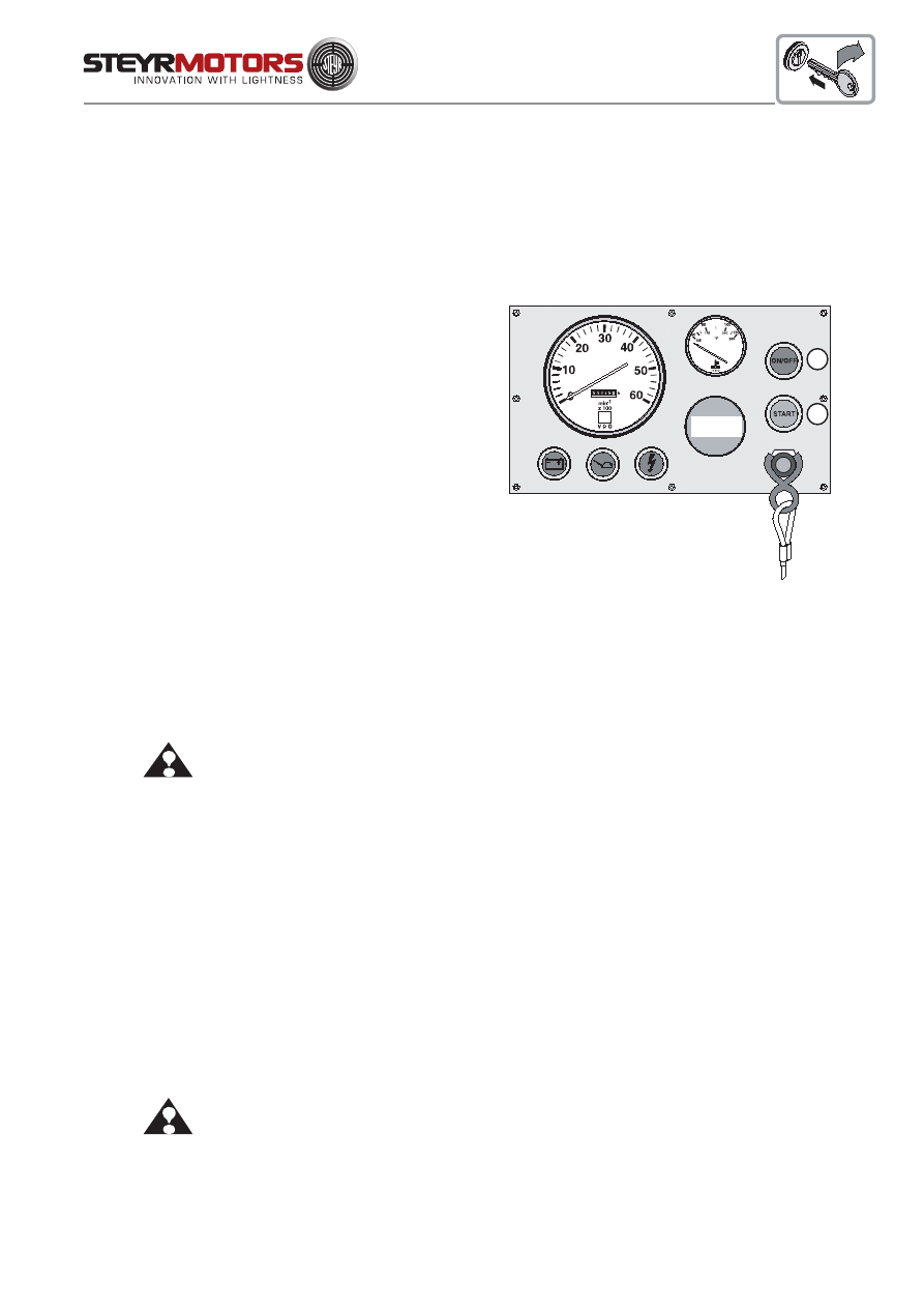
Starting the Engine
Starting procedure for the STEYR marine engine is the same for both cold and warm engines. The electronic
engine management system automatically regulates the fuel supply and the preheating period, for any
given temperature. Therefore, the throttle lever should remain in neutral position.
1. To start the engine, move throttle lever into
idle position and gear into neutral position.
2. Turn ignition key into position ignition
"ON".An audible alarm will sound and the
check are illumiated (temporary), indicating
the correct function of the audible warning
system.
NOTE:
In case of a low temperature start wait
until the combined oil pressure/glow plug
pre-warming indication light is turned off, before
you continue with the start procedure.
3. Turn ignition key into position "START"
and hold in this position until "starting" of
engine, but under no circumstances hold in
this position for more than ten seconds.
If engine does not start, release ignition key
momentarily and repeat starting procedure.
4. As soon as engine starts, release ignition
key. The audible alarm will stop when normal
oil pressure has been reached.
ATTENTION: If engine fails to start within one minute and/or repeated attempts, contact your STEYR
Marine dealer.
Never turn ignition key to position "START" when engine is running.
Stopping the Engine
1. Move throttle lever into idle position and gear in neutral position.
2. Cool down the engine.
3. Turn ignition key to OFF position.
ATTENTION:
Do not stop engine at speeds above idle or “accelerate” engine while turning off
ignition. This may result in engine failures.
OFF ON
(VOID)
START
OPTIONAL
INSTRUMENT
17
Starting the Engine (for SOLAS only)
Starting procedure for the STEYR marine engine is the same for cold or warm operating condition. The
electronic engine management system automatically regulates the fuel supply and the preheating period,
for any given temperature. Therefore, the throttle lever should remain in neutral position.
1. To start the engine, move throttle lever into
idle position and gear into neutral position.
2. Press the push button for ignition (ill.F; red)
(push button lock in place); An audible alarm will sound
and the check lights are illumiated (temporary), indicating
the correct function of the warning system.
NOTE:
In case of a low temperature start, wait
until the combined oil pressure/glow plug
pre-warming indication light is turned off, then
continue with the start procedure.
3. Press the button START (ill.G; green) and hold in
this position until "starting" of engine, but under no
circumstances hold in this position for more than ten
seconds.
If engine does not start, release start - push button
momentarily and repeat starting procedure.
4. As soon as engine starts, release switch start.
The audible alarm will stop when normal
oil pressure has been reached.
ATTENTION: If engine fails to start within one minute and/or repeated attempts, contact your STEYR
Marine dealer.
Never push start button to position "START" when engine is running.
Stopping the Engine
1.
Move throttle lever into idle position and gear in neutral position.
2.
Cool down the engine.
3.
Press push button ignition ON/OFF (ill.F) to disengage from locking position and to shut
OFF the engine.
ATTENTION: Do not stop engine at speeds above idle or “accelerate” engine while turning off
ignition. This may result in engine failures.
F
G
OPTIONAL
INSTRUMENT
BUKH STEYR SOLAS
18
Engine Break-In procedure
All STEYR Marine engines have been run for a short period as a final test at the factory. You must follow the Engine
Break-In instructions during the first 20 running hours to ensure maximum performance and longest engine life.
NOTE: NONOBSERVANCE OF BREAK-IN INSTRUCTIONS MAY CAUSE SEVERE ENGINE FAILURE.
First Two Hours
For the first five to ten minutes of operation, run engine at a fast idle (below 1500 RPM). For the remaining first two hours
of operation, accelerate to bring boat onto plane quickly and bring throttle back to maintain a planing attitude. During
this period, vary the engine speed frequently by accelerating to approximately three-quarter throttle for two to three
minutes, then back to minimum planing speed.
When the engine has reached operating temperature, reduce engine speed, then increase engine speed again, to
assist the break-in of rings and bearings. Maintain planing speed to avoid excessive engine load.
NOTE:
DO NOT RUN ENGINE AT A CONSTANT RPM FOR LONGER PERIODS
DURING THIS INITIAL TWO HOURS OF BREAK-IN.
ATTENTION: Warning indication engine over load during break - in via ECU (Engine Control Unit)
The ECU controls during the first two hours of engine operation the load on the engine. If
the engine is overloaded (during the first 2 hours of running) the "Check Engine Light"
will automatically illuminate.
If the warning light illuminates (CEL light - ON), the throttle position must be reduced
until this signals are extinguish.
Next Eight Hours
For the next eight hours, continue to run engine at approximately three-quarters throttle or less (minimum planing
speed). Occasionally reduce throttle to idle speed for cooling down. During this eight hours of running it is permissible
to run at full throttle for periods of less than two minutes.
NOTE:
DURING BREAK-IN, DO NOT RUN ENGINE AT A CONSTANT RPM
FOR LONGER PERIODS.
ON
19
Final Ten Hours of Break-in
During the final ten hours of break-in, the engine may run at full speed for five to ten minutes. After warming up the engine
to operating temperature, momentarily reduce the engine speed and then increase it again.
Occasionally reduce the engine speed to cool is down.
NOTE:
DURING THE BREAK-IN PERIOD, THE ENGINE MUST NOT BE OPERATED AT
CONSTANT RPM FOR LONGER PERIODS.
During break-in period, be particularly observant of the following:
A.
Check motor oil level daily. Always maintain oil level in the desired range between the "MIN" and "MAX"
marks on dipstick.
When refilling motor oil, refer to information "Engine Lubrication - Motor Oil" (page 41).
B.
Check oil pressure control lamp. If the lamp lights up as soon as the boat changes its position (while turning,
straightening up the boat or planing), check the oil level in the engine housing by means of dipstick. If necessary,
add oil (DO NOT OVERFILL). In case that the oil pressure control lamp is still illuminated with correct oil level,
have the engine checked by your STEYR Marine dealer as to malfunction of signal or oil pump.
NOTE:
During normal operation of engine, oil pressure will rise as RPM increases and fall as
RPM decreases. In general, oil pressure will be higher with cold motor oil and specific
RPM than with hot motor oil.
C.
Check engine temperature indication. Normal operation between 80° - 95°. In case of audible alarm, check
coolant level in expansion tank (only with cold engine).
D.
Deviations from normal operating conditions will be indicated by warning lights and audible alarm. As to exact
meanings see page 62 - 65
ATTENTION: In case of nonobservance of break-in instructions, warranty will expire.
Engine to be filled with recommended oil quality only. See chapter "Engine Lubrication".
GENERAL

20
Operation after Break - In
The engines specified in this manual are intended to be operated at different speeds and loads, but not allowing full-
load of the engine for more than one hour per 12 running hours. Economic driving may be achieved at the following
speeds:
3000 rpm.
3000 rpm.
3000 rpm.
3200 rpm.
3200 rpm
3400 rmp
2200 rpm
2200 rpm
3300 rpm
3600 rpm
3600 rpm
which will prolong engine life and reduce sound emissions.
When starting a cold engine, always allow the engine to warm up slowly. Never run the engine at full speed until
operating temperature is reached. During the first 50 running hours, check the oil level frequently.
M 0 8 4 K 3 2
M 0 9 4 K 3 3
M 0 1 1 4 K 3 3
M0144M38 + BUKH STEYR SOLAS
M0144V38 + BUKH STEYR SOLAS
M0164M40 + BUKH STEYR SOLAS
GENERAL
M 0 1 2 6 M 2 8
M 0 1 6 6 K 2 8
M0236K42 + BUKH STEYR SOLAS
M O 2 5 6 K 4 3
M O 2 5 6 H 4 5

21
Shifting
1. If the gear shift mechanism is disengaged, move the control lever to neutral position. The shift mechanism will
automatically engage.
2. To go FORWARD - press the neutral lock button and move the control lever forward. Throttle movement will
begin after forward gear engagement.
3. To go in REVERSE - press the neutral lock button and move the control lever backwards. Throttle movement
will begin after reverse gear engagement.
4. To go from FORWARD to REVERSE, or REVERSE to FORWARD, always pause at NEUTRAL and allow
engine speed to return to idle.
5. After shifting is completed, continue to move the control lever slowly in the desired direction to increase speed.
NOTE:
A sudden increase in shifting effort on the remote control lever indicates a possible problem in the
shifting system. If so, see your STEYR dealer as soon as possible for proper diagnosis and
and necessary service adjustment. Continued operation under this condition could result in
damage to the shifting mechanism.
22
Remote Control Operating Instructions
Your boat may be equipped with one of the following remote
controls:
* Single lever concealed side mount control
* Dual lever binnacle mount control for twin engines
NOTE:
If other than STEYR matched remote controls are used,
follow the manufacturer's recommendation.
Remote controls have the following important features:
* A single lever which allows to select forward or reverse gear, regulate engine speed, and ensure shifting
is done at low engine speed.
* A start-in-neutral-only feature which will protect you from starting your STEYR Marine Engine with
engaged gears.
The concealed side mount control has a neutral lock button ( C ) located in the control lever which must be pressed
to permit shifting from neutral to forward or reverse. The binnacle mount controls do not have a neutral lock, but there
is a neutral ratchet position.
Concealed Side Mount Control
* To disengage shift mechanism:
1. Place control lever into neutral position ( D )
2. Press both neutral lock button ( C ) and shift disengage button ( E ).
3. Move control lever forward to increase throttle
( F )
Shift Mechanism Engaged
( G )
Shift Mechanism Disengaged
The neutral lock and shift mechanism will automatically engage when the control lever is returned to neutral position.
Binnacle Mount Control
* To disengage shift mechanism:
1. Grasp the control lever hub and pull straight in for approximately 1/4 (6 mm).
2. Move control lever forward to increase throttle.
The shift mechanism will automatically engage when control lever is returned to neutral.
Your boat may be equipped with remote controls other than those described above. When not using STEYR marine
engine matched controls, ask your DEALER for operating instructions for the remote control used in your boat since
operation and function may differ from STEYR marine engine matched remote controls.
ATTENTION:
Your boat should be equipped by manufacturer with a remote control with protection
against starting in gear. Only use a remote control with start-in-neutral-only feature.
This feature can prevent injury resulting from unexpected turning of the propeller and
sudden movement of the boat.
1
1
23
2
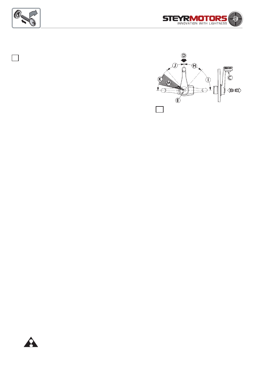
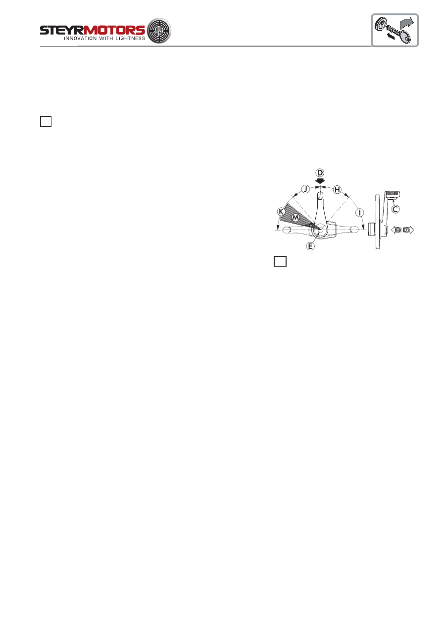
How to Shift and Control Speed
NOTE:
Do not shift into FORWARD or REVERSE unless engine is running. Damage to the shift mechanism
could result from trying to shift without the engine running.
Move the control lever to neutral position (D). The shift mechanism will automatically engage. Press neutral lock
button (C) on some single side mount control and move the control lever to shift into forward or reverse. The throttle
will begin to advance after gear engagement. Continue to move the control lever slowly in the desired direction to
increase speed.
(H)
Reverse Shift Range
(I)
Reverse Throttle Range
(D)
Neutral position
(J)
Forward Throttle Range
(K)
Forward Shift Range
Fuel Economy
Using the fuel economy throttle range (M) can save fuel depending on boat load and hull design. When the boat reaches
top speed, reduce engine speed slightly. Make sure the boat maintains to plane when reducing engine speed. Continue
to reduce engine speed slightly while maintaining to plane. Do not allow boat to fall off plane. This will give a comfortable
ride and help to save fuel at the same time.
Gear Box - Information
NOTE:
You are requested to follow the instructions and recommendations provided by the marine gear box
manufacturer.
High Altitude Operation
Your STEYR Marine Engine is turbocharged, and there should not be any noticeable performance loss at high
altitudes.
2
24
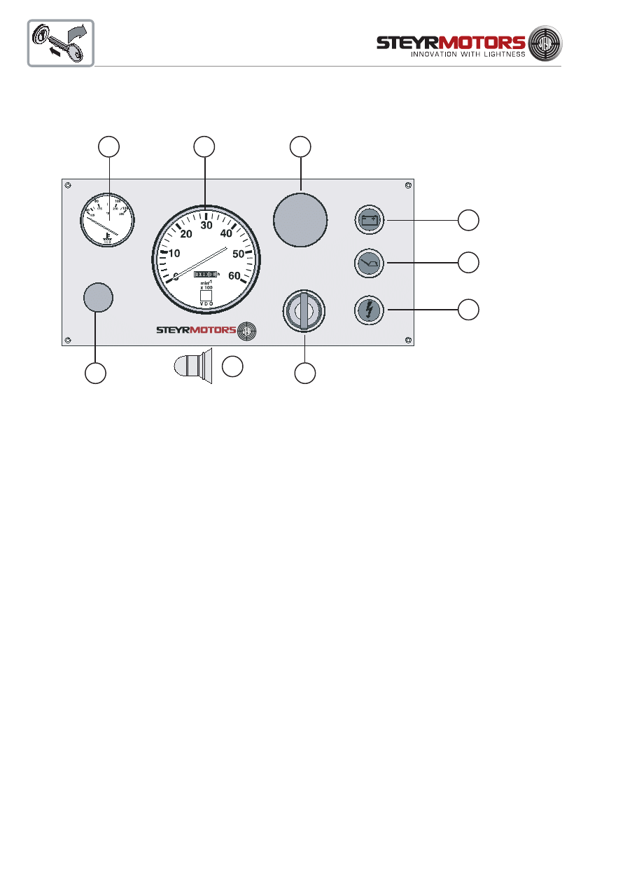
If you should need additional instruments or accessories, please contact your Steyr Marine dealer.
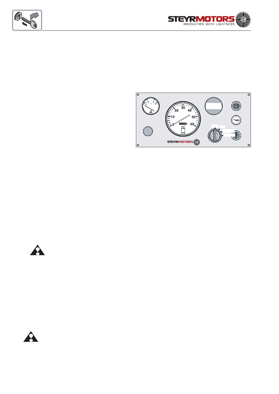
Instrument panel
B
A
H
C
D
E
F
G
Instrument panel, standard
A
tachometer
G
blind plug - installation option for
B
engine temperature
key switch constant revolution
C
warning light - battery charge
H
blind plug - installation option for
D
combined light preheating control &
oil pressure gauge or
warning light engine oil pressure
voltmeter 12V
E
warning light check engine
I
audible alarm
F
ignition key lock
(installed to rear side of paneel)
I
25
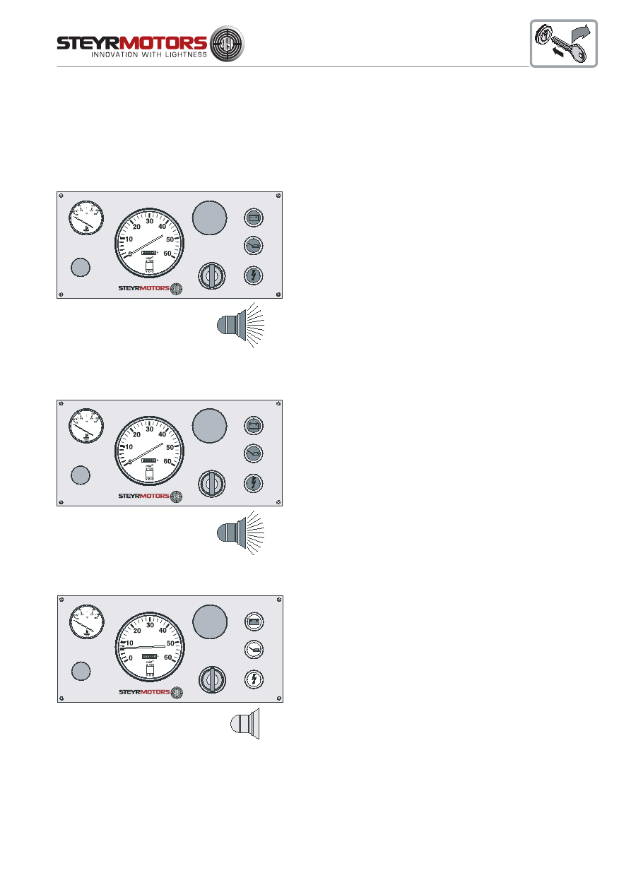
Instrument indication during normal operation
Chart - Operating Status
1. ignition ON (... until engine start)
ON (0,7 sec.)
ON (0,7 sec.)
ON
ON (0,7 sec.)
System check - see light indication
NOTE:
At low temperature condition (cold weather)
the combined light for glow plug preheating &
engine oil pressure will not extinguish after 0,7
sec. (glow plug preheating phase)
In this case start engine immediately after the
light extinguishes.
2. ignition ON (... until engine start)
ON (5 sec.)
ON (0,7 sec.)
ON
ON (5 sec.)
Indication active error
3. engine running after start
OFF
OFF
OFF
OFF
light indication
light indication
NOTE:
Further information see:
"Table - Error indication on Instrument
Panel"
Normal condition
26
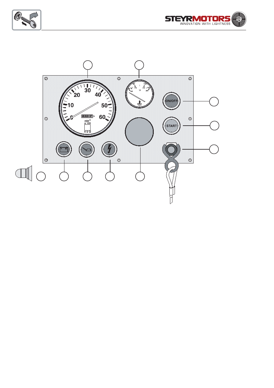
Instrument panel (for SOLAS only)
A
F
G
I
C
J
B
D
E
H
NOTE:
Instrument gauges are automatically illuminated if ignition is turned ON.
NOTE:
In the case of inversion the engine will be automatically shut off, in order to allow normal operation later.
The ignition push button (F) must be switched OFF and ON again, then the engine can be restarted via
the
push button START (G).
BUKH STEYR SOLAS
A
tachometer with
G
push button START (green)
service hour meter
B
temperature gauge - coolant
H
blind plug - installation option for
C
warning light - battery charge
oil pressure gauge or
D
combined light preheating control &
voltmeter 12V
warning light engine oil pressure
E
warning light - check engine light
I
emergency cut off switch
F
push button - ignition ON/OFF (red)
J
audible warning device
(installed to rear side of panel)
27
Instrument indication during normal operation
Chart - Operating Status (for SOLAS only)
BUKH STEYR SOLAS
1. ignition ON (... until engine start)
ON
ON (0,7 sec.)
System check - see light indication
NOTE:
At low temperature condition (cold weather)
the combined light for glow plug preheating &
warning light engine oil pressure will not
extinguish after 0,7 sec. (glow plug preheating
phase)
In this case start engine immediately after the
light extinguishes.
ON (5 sec.)
Indication active error
OFF
NOTE:
Further information see:
"Table - Error indication on
Instrument Panel"
Normal condition
ON (0,7 sec.)
ON (0,7 sec.)
ON
ON (0,7 sec.)
ON (5 sec.)
2. ignition ON (... until engine start)
3. engine running after start
28
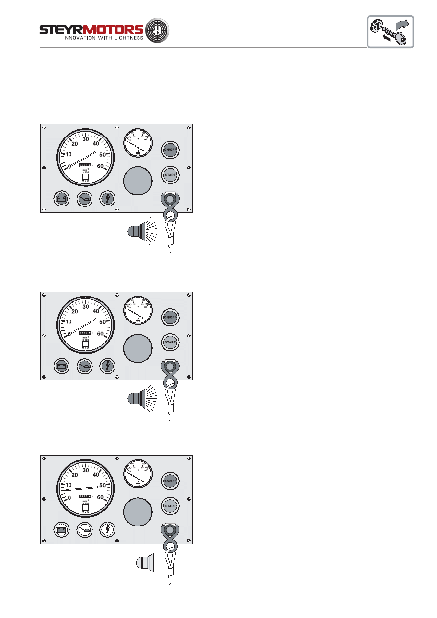
Emergency Stop Switch
An emergency stop switch may be a feature of your boat. Use
of this switch is highly recommended. To properly use this feature,
attach the lanyard securely to your clothing. Do not attach the lanyard
to clothing that will tear away before the lanyard is pulled from switch
to stop the engine. Using this switch is simple and should not interfere
with normal operation of the boat. Care must be taken to avoid
accidental pulling of lanyard during normal operation. Unexpected
loss of forward motion will occur. This could allow occupants to be
thrown forward. If the emergency stop switch has been activated, any
occupant of the boat can restart the engine. Press in and hold the
emergency stop switch button, then follow normal starting procedure.
When the button is released, the engine will stop.
ATTENTION:
The emergency stop switch can only be effective when in good working condition.
Observe the following:
*
Lanyard must always be free of entaglements that could hinder its operation.
*
Once a month, check switch for proper operation. With engine running, pull lanyard.
If engine does not stop, see your DEALER for replacement of switch.
3
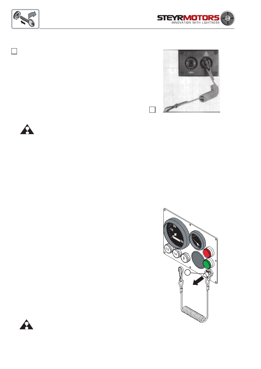
Emergency cut off switch (for SOLAS only)
An emergency cut off switch is a feature on this instrument
panel. Use of this switch is highly recommended. To properly
use this feature, attach the lanyard securely to your clothing. Do
not attach the lanyard to clothing that will tear away before the
lanyard is pulled from switch to stop the engine. Using this
switch is simple and should not interfere with normal operation
of the boat. Care must be taken to avoid accidental pulling of
lanyard during normal operation. Unexpected loss of forward
motion will occur. This could allow occupants to be thrown
forward. In case the emergency cut off switch had been
activated (lanyard pulled) the engine can be restarted by a
person if; the pull knob (ill. pos.1) of the emergency switch is
being pulled and held in this position. While holding the pull
knob proceed with the normal start procedure and start engine.
The engine will immediately stop if the pull knob is released
under this circumstances.
ATTENTION: The emergency cut off switch can only be
effective when in good working condition.
Observe the following:
*
Lanyard must always be free of entaglements that could hinder its operation.
*
Once a month, check switch for proper operation. With engine running, pull lanyard.
If engine does not stop, see your DEALER for replacement of switch.
If your boat is not equipped with an emergency stop switch and belongs to one of the following categories, installation
of an emergency stop switch is recommended.
* High-performance sport boats
* Small runabouts or bass boats
* Boats with sensitive steering
* Boats where the distance from the top of the gunnel down to the drivers seat is less than 12 in. (30,5 cm).
* Rescue boats
See your STEYR Marine dealer for installation of an emergency stop switch.
3
1
BUKH STEYR SOLAS

29
Warning lights and audible alarm
Your boat with the STEYR Marine Engine engine is equipped with three warning lights and one audible alarm (mounted
below the instrument panel) to indicate the following operation condition or system deficiencies. (the ECU will also
reduce the engine power in case an important operating parameter limit has been exceeded)
* Indication Pre-warming Phase (combined indication through oil pressure light. Becomes affective if ambient
engine coolant temperature is below 20 °C / 68 °C)
* Break - In; over load warning
* engine oil pressure too low
* high coolant temperature
* Sensors or sensor circuit defect
After ignition is turned "ON" the indication / warning lights are illuminated and the warning horn will sound for less then
a second (0,7 sec.) this serves as a functional check for the optical / audible warning system.
The indication light and the warning horn remain switched on for 5 sec. after ignition "ON" if a sensor or sensor circuit
defect have been detected and stored in the Engine Control Unit (ECU)
(see for indication on instrument panel page 25 to 27 and 62 to 65)
Please contact your nearest STEYR Marine Dealer to get proffesional assistance to verify the deficiency and to correct
any possible failure.
If the engine oil pressure is too low, the warning light "engine oil pressure" lights and the audible alarm sounds. The
engine will be limited. In this case proceed as follows:
* Check engine oil level, respectively add engine oil if necessary (refer to chapter Fuel and Lubricants)
* Restart engine and watch the oil pressure light. The warning light has to extinguish within 3 or 4 second after
the start. If this does not happen the engine must be stopped immediately. (Ignition "OFF")
In case of an overheating of the exhaust gas cooling system, the warning light "engine control" flashes and the audible
alarm sounds (2 times per second); the engine power is reduced. In this case, proceed as follows:
* IMMEDIATELY reduce the engine to idle speed.
* Check an clean the raw water filter.
* Check the coolant temperature gauge for overheating of engine coolant. If the coolant temperature gauge
indicates overheating of engine coolant, switch for a short time to REVERSE to remove a possible clogging
of the raw water inlet through large plastic parts etc. , and then to FORWARD. Let the engine run at idle speed
for some minutes. If the temperature gauge still indicates an overheating of the engine, the engine is to be
stopped. Restart the engine only after having found and eliminated the cause for alarm. See “loss of
power” in Trouble Shooting Chart, Technical Data and in section Maintenance. Check coolant level
and if necessary, refill coolant until an adequate coolant level is achieved in the heat exhanger. If the cause
for optical/audible alarm cannot be found, consult your STEYR Marine dealer.
30
Electronic Engine Control Unit
The STEYR Marine engine is equipped with an Electronic Engine Control Unit (ECU) that
performs the following:
* controls engine functions to ensure maximum efficiency.
* self-diagnostic to protect the engine from damage if operating parameter are exceeded.
* stores diagnostic data of ECU server circuits for maintenance and service.
* stores abuse data
Engine power is reduced if:
Operating Parameter
High engine coolant
temperature
limit exceeded
Defect - engine coolant
sensor or
sensor connection
Exhaust temperature
limit exceeded
Defect - Exhaust
temperature sensor or
sensor connection
Oil pressure below limit
Defect - Oil pressure
sensor or sensor
connection
Insufficient boost
pressure or defective
sensor
Additional
Tool-Readings
Steyr Diag
Power limitation
Steyr Diag
Service code
Steyr Diag
Power limitation
Steyr Diag
Service code
Steyr Diag
Power limitation
Steyr Diag
Service code
Steyr Diag
Power limitation
Panel
Indication
Horn ON 2x p. sec.
Gauge reading >
107 °C
Horn ON 2x p. sec.
Gauge reading >
120 °C
Horn and indication
light "CEL" ON 2x
p. sec.
Horn and indication
light "CEL" ON 2x
p. sec.
Horn continuous and
Oil indication light
continous switched
ON
Oil pressure indication
light switched ON 1x
p. sec.
Effect
noticed
Reduction of
engine speed
Reduction of
engine speed
Reduction of
engine speed
Reduction of
engine speed
Reduction of
engine speed
Reduction of
engine speed
Reduction of
engine speed
Action or
possible reason
See table trouble
shooting:
Cooling system
Sensor or connector
failure; see service
code table
See table trouble
shooting: Raw water
cooling system
Sensor or connector
failure; see service
code table
See table trouble
shooting:
Engine oil system
Sensor or connector
failure; see service
code table
See table trouble
shooting:
Air charge system
Steyr Diag
Service code
Steyr Diag
Service code
Steyr Diag
Service code
No RPM indication
on tachometer
Higher or
unstable idle
speed, limited
performance
No increase of
engine speed if
throttle is moved
to max.
Irregular engine
speed or stalled
engine
See table trouble
shooting:
Speed sensor
See table trouble
shooting:
Accelerator
potentiometer failure
See table trouble
shooting:
Governing system
Engine speed sensor
fault
Engine speed remains
at idle
Governor position
system

31
Operating Parameter
Inverse position shut
down (SOLAS)
During break in phase
Additional
Tool-Readings
Steyr Diag
Break-in
phase
Panel
Indication
After engine stop
horn remains
switched ON until
ignition reset
Indication light
"CEL" is switched
ON
Effect
noticed
Engine shut
down beyond
70° deg. angle
Cel-ON at high
accelerator
position (more
than 75%)
Action or
possible reason
Reset through ignition
OFF and then ON
See information break
in procedure
Diagnostic system
The electronic engine control unit monitors the following engine parameters:
oil pressure, boost pressure, coolant temperature, exhaust pipe temperature (Hi-riser), sensor control rack,
potentiometer accelerator, speed signal
The ECU carries out self-diagnostic and/or plausibility checks for all input values and
sensor connections. In case of irregularities, there is an optical or audible warning signal. (see page 69)
Existing active failures remain stored until the problem has been solved and the code has been cleared from the
memory.
To select stored error codes, a PC with diagnostic program (VR00134/0) or diagnostic tool (VR00135/1) is
necessary.
Malfunction during operation is ranked in three different categories intermittent failure, non essential failure and
essential failure.
Optical and accustical warning signals are explained on the following tables.
"Operating Status and Error Report"
(see pages 25-27) (see pages 62-65)
32
4
5
7
6
Counter-Rotation Models
All STEYR Marine Engine inboard models can also be set up for
counter-rotation for twin installation. This is done by inversing direction
of cable lines on shift lever in order to achieve a counter-rotation of
propeller.
Counter-rotation is accomplished in the gearbox. The propeller,
propeller shaft and output gear are the only parts that counter-rotate.
The engine always has standard rotation.
It is customary to operate your propeller as shown on this
illustration for twin installation.
Some boat manufacturers may set up twin installations the opposite
way. When propellers and/or cable lines are removed, care must be
taken to attach them at the same position as before, and that the
propellers are not exchanged.
Optional Propellers
Propellers are available in all regular sizes for both right- and
left-hand rotation. Stainless steel has greater strength and durability
than aluminium. This allows the stainless steel propeller blades to be
thinner and still maintain more beam strength than aluminium propel-
lers. The result is a more efficient propeller that gives better perform-
ance and more fuel economy.
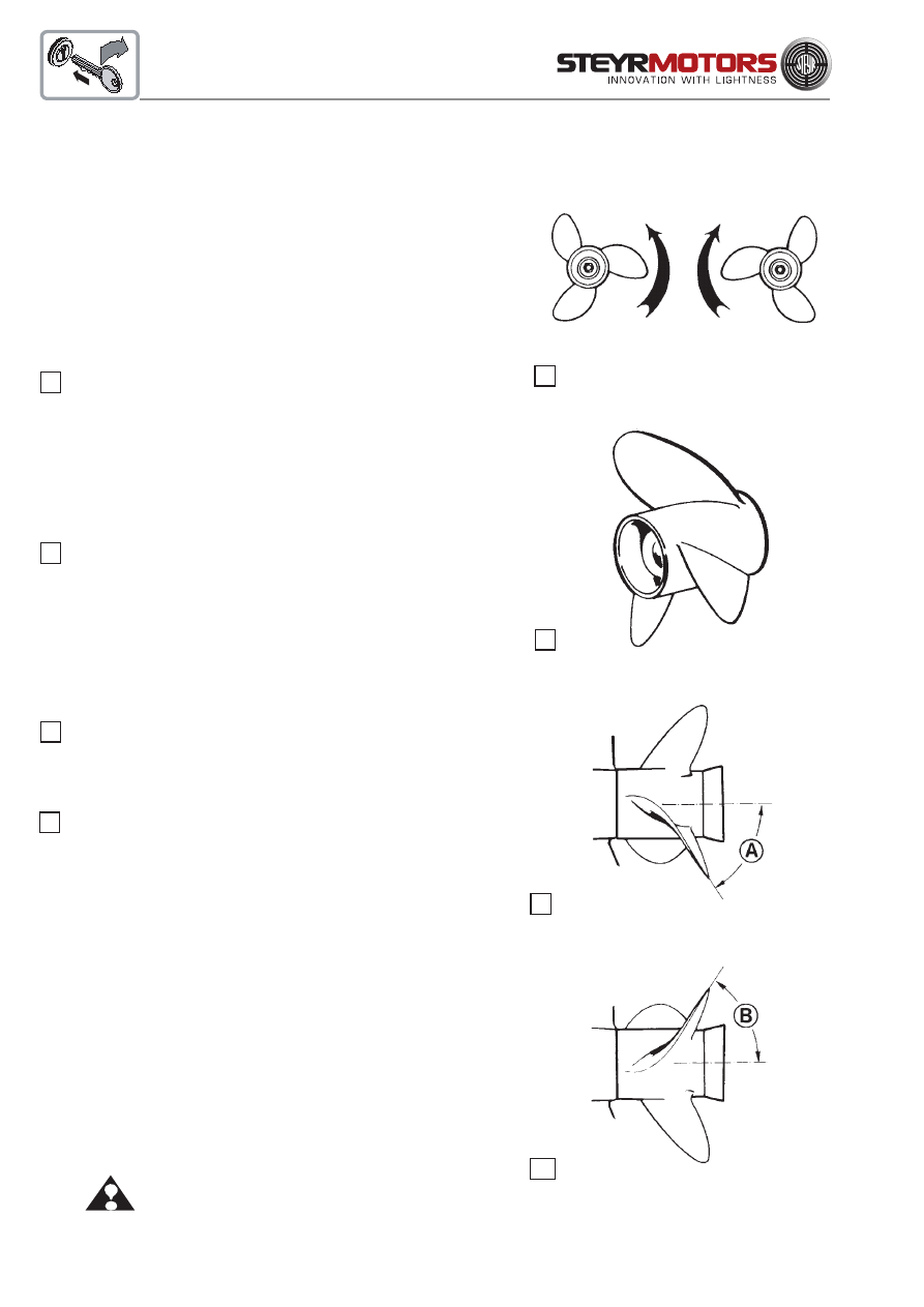
Propellers
Right-hand propellers rotate clockwise to propel a boat for-
ward. Right-hand propellers are considered standard-rotation propel-
lers. To identify a right-hand propeller, note the angle (A) of the blade
as seen from portside.
Left-hand propellers rotate counterclockwise to propel a boat
forward. Left-hand propellers are considered counter-rotation propel-
lers. To identify a left-hand propeller, note the angle (B) of the blade
as seen from portside.
NOTE:
Never interchange a right-hand propeller with a left-
hand propeller. This would result in the boat being
propelled in reverse when propulsion units are operated
in forward gear, and forward when propulsion units are
operated in reverse gear. To help you better understand
and show the difference between left-hand and right-
hand propellers, see illustrations.
After having the propellers serviced, always shift into FORWARD or
REVERSE at idle speed and determine wether the boat moves in the
right direction. If the boat moves in the OPPOSITE direction, the
propellers have not been installed properly.
ATTENTION:
Failure to perform above test could
result in loss of control.
4
5
6
7

33
Operating Procedure for Freezing Temperatures
When freezing temperatures are forecast and the boat will be operated and left in the water, the propeller must remain
in the tilted down (submerged) position at all times to prevent water in the vertical drive from freezing. Upon completion
of engine operation, drain the engine as described in Off-Season Storage Preparations.
Salt Water Operation
Fresh water to flush the raw water circuit is recommended after use in salt, polluted, or brackish water to prevent deposits
from clogging and corroding the cooling passages. Contact your STEYR Marine dealer to obtain an Engine Flushing
Kit that allows flushing of the engine when in or out of the water.
NOTE:
Use in salt or brackish water may require additional anti-corrosion protection.
Propeller Torque
The torque of the propeller creates forces that are transmitted to the boat. This can cause the boat to lean to one side
(list).
The forces created by the counter-rotating propeller are opposite to the forces created by the standard rotating propeller.
When the vertical drives are trimmed equal, these opposite forces balance each other.
Propeller care
A damaged or unbalanced propeller will cause excessive vibration and a loss of boat speed. Under these conditions,
stop the engine and check the propeller for damage. If the propeller seems to be damaged, have it checked and repaired
by your local STEYR Marine dealer. Always carry a spare propeller and replace the damaged propeller as soon as
possible.
NOTE:
Never run with a damaged propeller. Running with a damaged propeller can result in damage to
drive components and engine.
Water Jet
When using water jet drives, please contact your STEYR Marine dealer. As to information on function and application,
please refer to respective documents and documentation of the drive manufacturer.
34
Fuel Pump
The STEYR Marine Engine is equipped with an electric fuel pump. It is turned “ON” and “OFF” with the key switch. If
the engine is not started within 10 seconds after turning the key switch “ON”, the fuel pump is automatically turned off.
Fuel System Checks
Fill the tank with the recommended fuel. Keeping tanks full reduces water condensation and helps keep fuel cool, which
is important to engine performance.
Make sure that fuel supply valves (if used) are open, and valve cock seals are absolutely (gas) tight.
To insure a prompt start and an even run of the engine, the fuel system is to be rinsed by means of the electric fuel pump
(ignition "ON" several times for app. 10 sec.) before starting the engine the first time and/or after every replacement of
a fuel filter.
Refill at the end of each day´s operation to prevent condensation from contaminating the fuel. Condensation formed
in a partially filled tank promotes the growth of microbial organisms that can clog fuel filters and restrict fuel flow.
If the engine is equipped with a fuel/water separator, drain off any water that has accumulated. Water in fuel can
seriously affect engine performance and may cause engine damage. STEYR MOTORS recommends to install a fuel/
water filter with a flow rate of at least 200 l/h at a pressure difference of < 200 mbar.
Fuel Contamination
In the marine environment, the most likely fuel contaminants are water and microbial growth (black "slime"). Generally,
this type of contamination is the result of poor fuel handling practices. Black "slime" requires water in the fuel to form
and grow; the best prevention is to keep water content in storage tank to a minimum.
Treating fuel with microbial growth requires the use of fuel additive.
STEYR MOTORS does recommend the use of fuel additives such as Biobor JF, or equivalent, for treatment of
microbiological fuel contamination. Follow the manufacturers instructions for use. If treating fuel, frequent fuel filter
changes will be necessary until fuel system is purged.
NOTE:
A galvanized steel tank should never be used for fuel storage, because the fuel reacts
chemically with the zinc coating forming powdery flakes which can quickly clog the fuel filters
and damage the fuel pump and injectors.
35
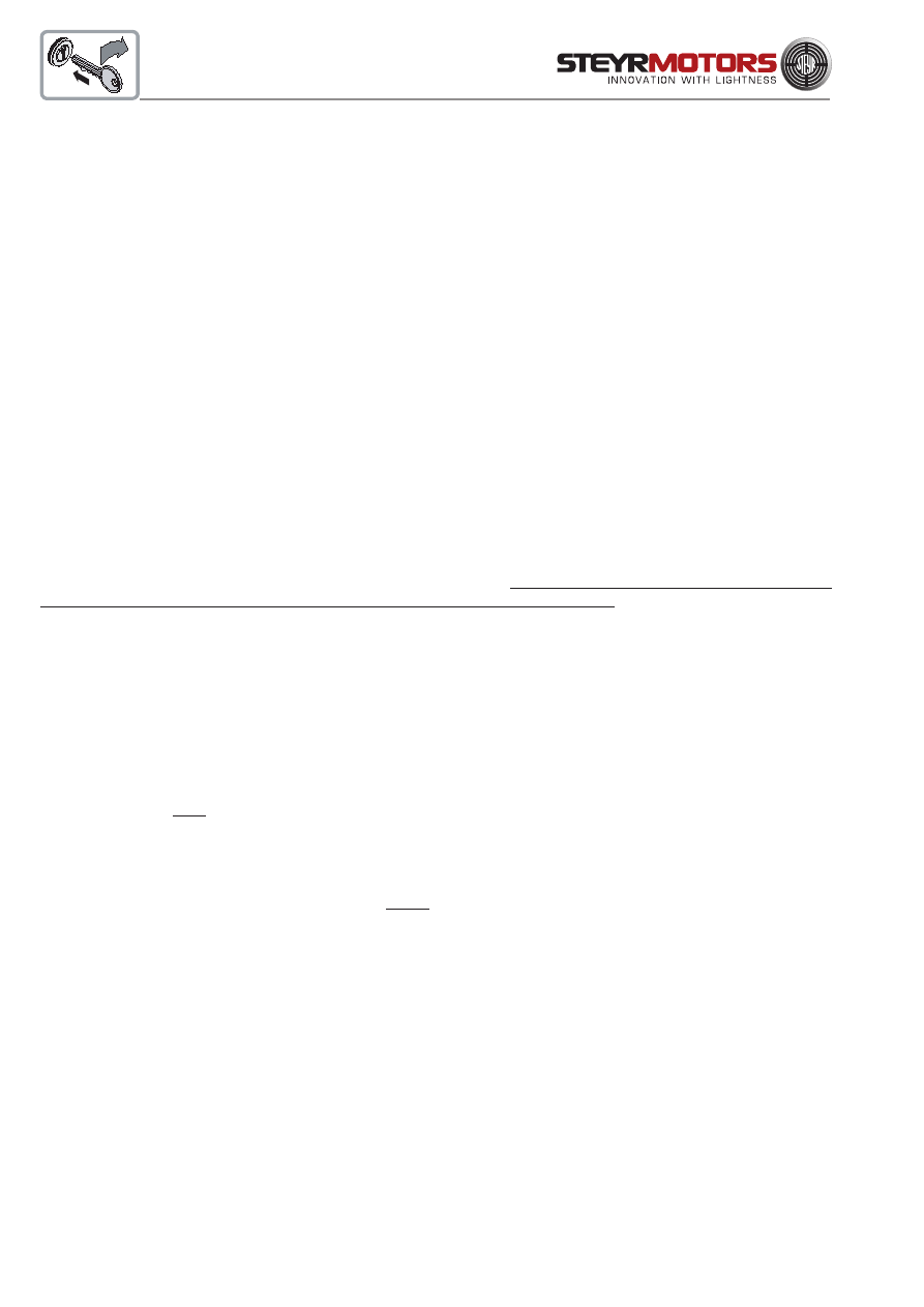
Cooling System (Function Description)
STEYR Marine Engines are equipped with a closed (internal) and an open (external cooling circuit).
Closed Cooling Circuit
The closed cooling circuit includes monoblock as well as exhaust
manifold, heat exchanger and expansion tank. Temperature in the
closed cooling circuit is precisely controlled by means of thermostat.
The thermostat determines the amount of coolant circulating through
the heat exchanger, thus controlling the operating temperature of the
engine.
A temperature sensor (8/A) controls the cooling temperature. An
excessive temperature rise of the coolant will cause an optical and
audible alarm (see chart "Error Report", page 60). In this case,
engine power will be reduced.
The temperature gauge on the instrument panel indicates the
coolant temperature of the engine.
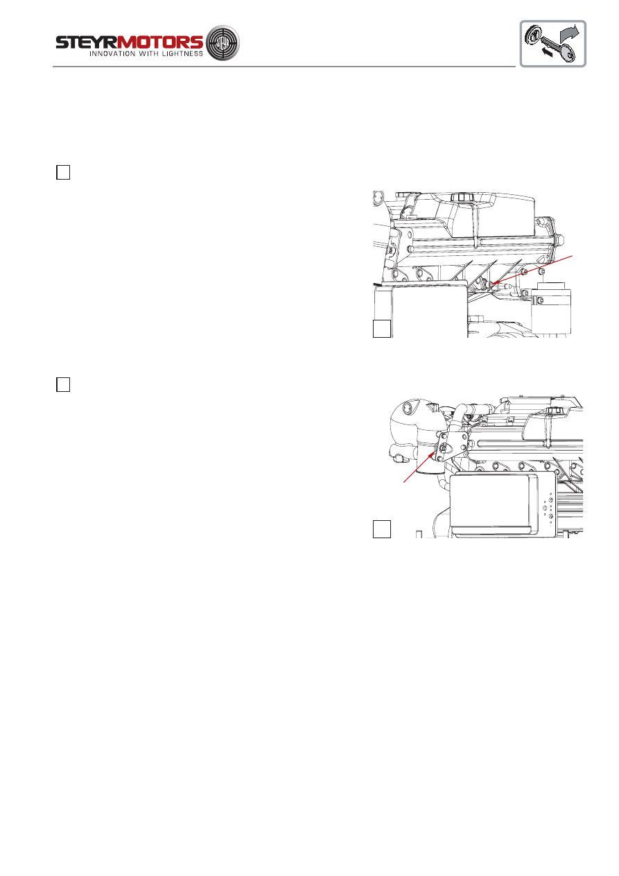
Open Cooling Circuit (Raw Water Circuit)
Thermal energy transfered by the engine and absorbed by the
engine coolant is drained via the (external) raw water circuit. Raw
water is sucked by the pump via the raw water intake, constantly
pumped through supercharger intercooler and heat exchanger,
and discharged together with the exhaust gas via the sprinkler.
During discharching, the raw water entering the exhaust pipe
aditionally cools the exhaust gas.
A temperature sensor (9/A) monitors the raw water- and exhaust gas
temperature. An excessive rise will cause an optical and audible
alarm (see chart "Error Report", page 60). In this case, the engine
power will be reduced too.
NOTE:
Should engine overheat at high speeds, slowly reduce RPM to idling to prevent damages
to the engine. In case of overheating problems, contact your STEYR Marine dealer.
9
8
8
06008
A
9
06009
A

36
Electrical Equipment
The electrical equipment of your STEYR Marine engine primarily consists of an alternator with transistorized voltage
regulator, battery and all necessary connecting cables and leads.
Alternator
The alternator is driven via a poly-V-belt from the 4 cyl. engines and via a V-belt from the 6 cyl. engines and
charges the battery at all engine speeds. Output at idle speed is ~ 30A / 12V and will rise with an engine speed of
3000 rpm. to maximum output of 90A / 12V.
Optional:
The 6 cylinder marine engines may be equipped with an optional 80A / 24V alternator and DC/DC charger system kit.
Battery
Use a 12-volt battery with a cold testing circuit of 450 A at -18°C and a capacity of 92 Ah at 27°C, to ensure the supply
of the electric and electronic components at all operating conditions.
Use a 12-volt battery with a cold testing circuit of 650 A at -18°C and a capacity of 115 Ah at 27°C, to ensure the
supply of all electric and electronic components.
FOR ALL 4 CYL. MARINE ENGINES
FOR ALL 6 CYL. MARINE ENGINES
GENERAL
37
ATTENTION
* Do not use jumper cables and a booster battery to start engine. Remove battery from boat and
recharge.
- WRONG CONNECTION WILL DESTROY ELECTRONIC SYSTEM -
* Do not charge battery in boat. Fumes vented during battery charging can lead to an explosion.
* Battery electrolyte is a corrosive acid and should be handled with care.
If electrolyte is spilled or splashed on any part of the body, immediately flush the exposed area with liberal
amounts of water and obtain medical aid as soon as possible.
High resistance in the charging circuit can seriously affect the operation of the electrical system. Unless there is definite
malfunction in the electrical system, high resistance is sometimes caused by corroded or loose connections. Wherever
practical, the electrical connections on your engine have been sealed. However, we recommend that you make periodic
inspections to ensure clean, tight connections throughout the electrical system.
NOTE:
It is important that the battery connections are correct. The negative battery cable must be attached
to the negative terminal (
-
) on the battery and the engine’s positive cable must be attached to the
positive terminal (
+
) on the battery. If these connections are reversed, the transistorized
regulating unit may be immediately damaged.
Inspect your battery at regular intervals for specific gravity (state of charge), individual cell water level, cleanliness and
clean, tight connections.
If the battery has become discharged for no apparent reason, check all electrical system components for malfunction,
or a switch left in ON position prior to installing recharged battery.
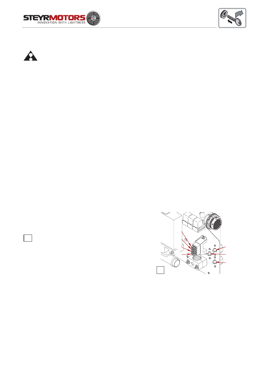
Circuit Breakers
STEYR Marine Engine models are protected against overload by
circuit breakers.
On the base plate of the E-box three thermical trigged 50 amp.
circuit breakers are installed. (F2) protects the electric circuit of the
glow plugs of cylinder 1 & 2 (4 cyl.) and 1-3 (6 cyl.); (F3) protects the
electric circuit for the glow plugs of cylinder 3 & 4 (4 cyl.) and 4-6 (6
cyl.); (F1) protects electric system and electronic management.
The ignition key and instruments are protected by a 10 amp. Fuse
located in the main wiring harness under the instrument panel (at
height of ignition key).
F4
Fuse supply module
F5
Fuse main circuit supply
F6
Fuse fuel-pump circuit
F7
Fuse glow-plug circuit
F9
Fuse ignition switch circuit (instrument panel)
The installation of any additional electrical accessories requires the protection of individual circuits. Consumption of
current should occur directly at the battery.
NOTE:
Avoid sparks that will damage the alternator or ECU. Do not attempt to connect or disconnect any part of
the electrical system while the engine is running.
Fuses for fuel, ECU-supply, glow plug-relay are inside the E-box cover.
10
06011
F4
F5
F6
F7
F2
F1
F3
10
38
Interrupt crankshaft housing ventilation
During an activation of the mercury switch inversion, the by-
pass valve (B) for crankshaft housing ventilation is closed too.
This avoids a possible oil outlet via sucking tract and air filter.
12
06010
B
Instrument Panel
The engines are supplied with the standard instrument panel.
The respective customer may use a self-adapted STEYR instrument panel or one which corresponds to his own ideas
and requirements.
ATTENTION:
For not approved alterations which lead to engine failure, no liability can be
undertaken.
Dry Operation
After a dry operation of the engine (without raw water cooling), check the impeller of the raw water pump for damages.
Replace if necessary. Grease the impeller, use grease from special impeller kit Z011753/2.
11
12
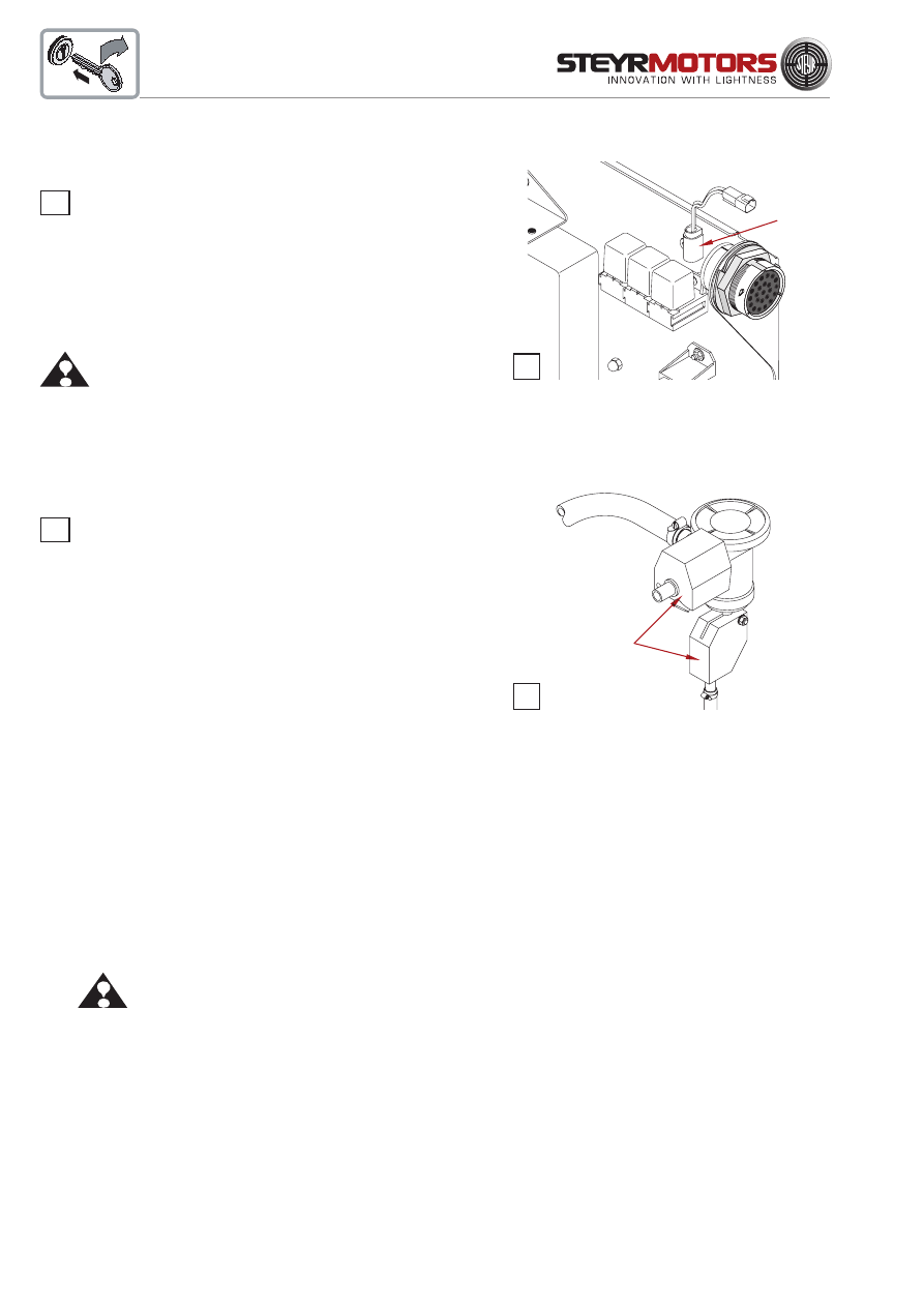
Inversion Switch
The inversion switch is a mercury switch (A) which is actuated
in case of a loop or an inclination of the boat in any some direction over
90°.
Via the main circuit relay the engine is shut down. For safeguarding
reasons the inversion switch is to be replaced every 1050
operating hours. (See service- and maintenance chart page 60)
ATTENTION:
After such an event, this temporarily stored
operating condition is to be cancelled from the
engine management system by ignition "OFF" =
Reset".
Without "Reset", a new start of the engine is
possible.
BUKH STEYR SOLAS
11
06012
A

39
FUEL AND LUBRICANTS
Fuel Requirements .................................................................................. 40
How to Select Fuel .................................................................................. 40
Fuel Selection Chart ................................................................................ 40
Engine Lubrication ................................................................................... 41
Motor Oil .................................................................................................. 41
Oil Identification Symbol .......................................................................... 41
Disposal of Automotive Waste Products .................................................. 42
40
Fuel Requirements
The STEYR Marine Engines are designed for maximum fuel economy. To maintain optimum performance, use
diesel fuel according to CEC RF-03-A-84 or equivalent to meet this specification. When temperatures are below
-7° C (20° F), use diesel fuels with additives for low temperature operation.
How to Select Fuel
Fuel quality is an important factor in obtaining satisfactory engine performance, long engine life, and acceptable
exhaust emission levels. Direct injected diesel engines are designed to operate with most diesel fuels marketed
today. In general, fuels meeting the properties of CEC RF-03-A-84 have provided satisfactory performance.
The ASTM D 975 specification, however, does not adequately define the fuel characteristics needed to
guarantee the fuel quality. The properties listed in the following fuel selection chart have provided optimum
engine performance.
Fuel Selection Chart
ASTM -
Test procedure
D 613 (D 976)
D 1298
D86
D 93
EN 116 (CEN)
D 445
D 1266/D 2622
D 2785
D 130
D 189
D 482
D 95/D 1744
D 974
D 2274
General
Fuel classification
Cetane number
Gravity at 15°C (kg/l)
Destillation
50%
90%
End point
Flash point
CFPP (Cloud point)
Viscosity Kinematic 40°C
Sulfur content
Copper corrosion
Carbon residue
Conradson number (10% settling)
Ash
Water content
Acid content (strong acid)
Oxidation stability
CEC RF-03-A-84
Limit value and
units
min. 49 - max. 53
min. 0,835
max. 0845
min. 245°C
min. 320°C
max. 340°C
max. 370°C
min. 55°C
min. -- / max. -5°C
min. 2,5 mm²/s
max. 3,5 mm²/s
min. (anzugeben)
max. 0,3 mass-%
max. 1
max. 0,2 mass-%
max. 0,01 mass-%
max. 0,05 mass-%
max. 0,20 mg KOH/g
max.2,5 mg/100ml
CEC RF-03-A-80
Limit value and
units
min. 51 - max. 57
min. 0,835
max. 0845
min. 245°C
min. 320°C
max. 340°C
max. 370°C
min. 55°C
max. -5°C
min. 2,5 mm²/s
max. 3,5 mm²/s
min. 0,20 mass-%
max. 0,50 mass-%
max. 1
max. 0,2 mass-%
max. 0,01 mass-%
max. 0,05 mass-%
max. 0,20 mg KOH/g
max.2,5 mg/100ml
41
Engine Lubrication
If you choose to lubricate your STEYR Marine Engine yourself, refer
to the Lubrication and Inspection Chart for lubrication points and
recommended lubricants. Use only STEYR recommended lubricants
or lubricants of equivalent quality and viscosity. See your STEYR
dealer for recommended lubricants.
If you choose to have your STEYR Marine Engine lubricated, see
your local STEYR dealer. He will gladly lubricate it at the required
intervals.
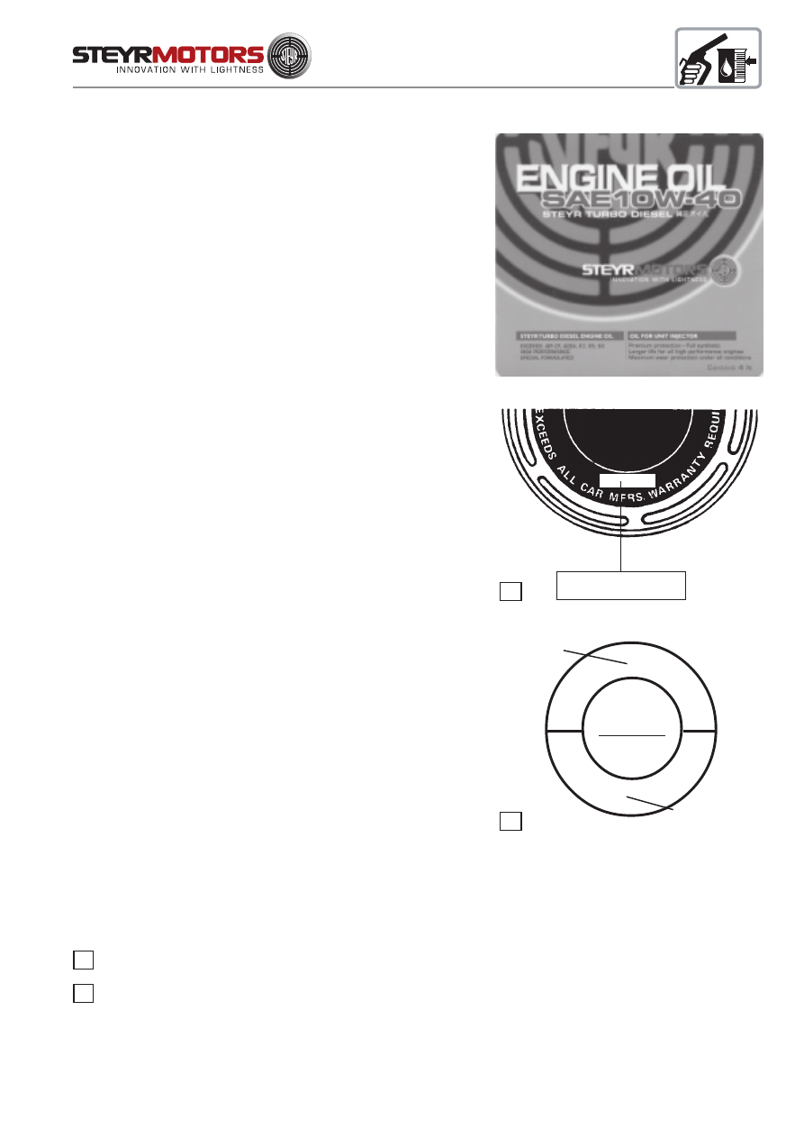
Motor Oil
To obtain the best engine performance and engine life, STEYR
TURBO Diesel Engine Oil SAE 5 W-50 or 10 W-40 (Z010058/0) is
recommended. Motor oils are specified by ACEA, API service codes
and SAE viscosity numbers. If STEYR TURBO Diesel Engine Oil is
not available, you are required to use a reputable brand of motor oil
labelled for ACEA E7 or B4-02, API CF Service codes and SAE
viscosity number 5 W-50 or 10 W-40. Refer to oil identification symbol
on the container.
Initial factory fill is a full synthetic high quality break-in oil specified
ACEA E7, API CF, SAE 10 W-40. During the break-in period
(initial 20 hours), frequently check the oil level. Somewhat higher oil
consumption is normal until piston rings are seated. The oil level
should be maintained between the minimum and maximum marks on
the dipstick. The space between the marks represents approximately
2 quarts (2 litres). For oil level dipstick location, refer to section
Maintenance
At the end of the break-in period, change the motor oil and replace the
oil filter. Refer to Lubrication and Inspection Chart for recom-
mended oil change intervals.
Oil Identification Symbol
Motor oils are specified by ACEA, API service codes, and SAE
viscosity numbers. These may be found on the label, top of can, or oil
identification symbol.
NOTE:
Some oils meet more then one ACEA or API service
rating. The recommended ACEA or API service codes
must be among these service ratings.
Top of Can
Oil Identification Symbol
14
13
14
SAE
5 W-50
10 W-40
API
SERVICE CODE
CF
13
ACEA E7 or B4 - 02
FOR HEAVY DUTY
DIESEL ENGINES
ACEA E7 or B4-02
API CF
42
Disposal of Automotive Waste Products
Used fuel and oil is to be collected in separate containers to permit an eventual subsequent treatment.
THE DISPOSAL OF ANY FUEL AND OIL FOR THE ENGINE IS SUBJECT TO THE SPECIAL
WASTE ACT. THE "SPECIAL WASTE CATALOGUE" ÖNORM S2100 REFERS TO THE
NECESSARY DISPOSAL IN AUSTRIA. PLEASE FOLLOW THE LOCAL REGULATIONS OF
YOUR COUNTRY.
The operating and maintenance personnel has to take care that fuel and oil as well as other material ranking as
special waste are deposited at the respective collecting points.
Code No.
Designation
31 423
oil contaminated ground or oil binder
54 102
waste oil
54 104
fuel
54 202
grease
54 207
vaseline
54 917
compact sealing material
54 927
oil contaminated scouring cloth
54 928
usel oil- and air filters
55 510
colour- or varnish containing waste

43
TECHNICAL DATA
Model and Serial Numbers ................................................................................. 45
Technical Data and Overview MO84K32, MO94K33 MO114K33, MO144V38 ... 46
Technical Data and Overview MO144M38, MO164M40 ..................................... 48
Technical Data and Overview MO126M28, MO166K28, MO196K35,
MO236K42 ......................................................................................................... 50
Technical Data and Overview MO256K43, MO256H45 ..................................... 52
full load
speedrange
100%
90%
80%
70%
60%
50%
40%
30%
B
C
D
RPM
A
OUTPUT POWER

44
full load
speedrange
100%
90%
80%
70%
60%
50%
40%
30%
B
C
D
RPM
A
OUTPUT POWER
45
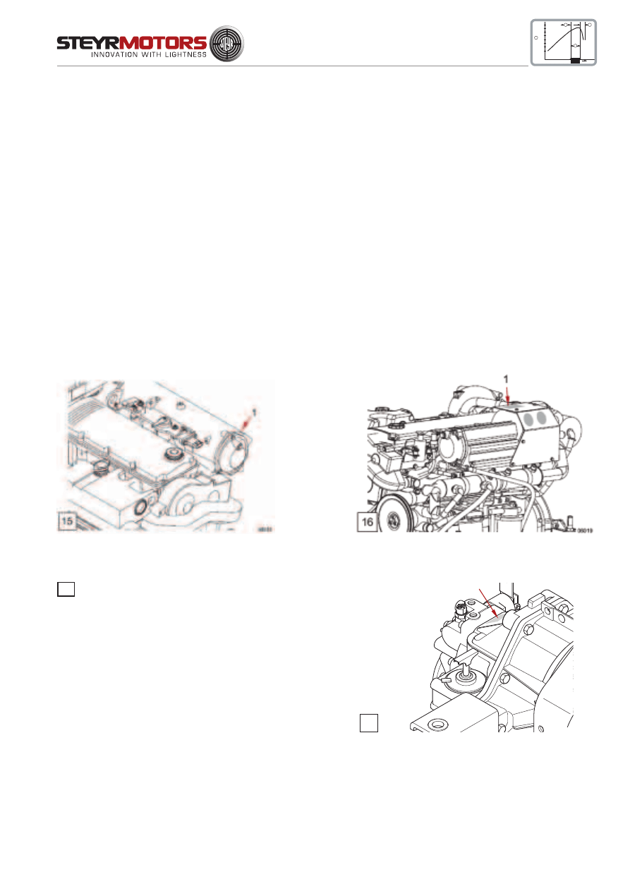
The primary model and serial number (see ill. 15/16) is
located on the engine as illustrated.
These numbers are required for warranty
claims and ordering parts.
The model and serial number of the marine gearbox
is located on the marine gearbox housing as illustrated.
To obtain instructions regarding marine gearbox
operation, refer to marine gearbox owners manual.
Model and Serial Numbers
GENERAL
17
full load
speedrange
100%
90%
80%
70%
60%
50%
40%
30%
B
C
D
RPM
A
OUTPUT POWER
17
06014
FOR ALL
6 CYL. MARINE ENGINES
FOR ALL
4 CYL. MARINE ENGINES

46
Technical Data
MO84K32
MO94K33
MO114K33
MO144V38
full load
speedrange
100%
90%
80%
70%
60%
50%
40%
30%
B
C
D
RPM
A
OUTPUT POWER
MAKE
STEYR M 14 TCM, TCAM
type
MO84K32
MO94K33
MO114K33
MO144V38
displacement
2133 cm³
piston displacement
85,0 x 94,0 mm
rated power acc. EN ISO 8665:2006
(crankshaft) KW / HP
55/75
66/89
81/110
106/144
number of cylinders
4-cylinder in-line engine (position of cyl. 1 at vibration damper side)
ignition order
1 - 3 - 4 - 2
sense of rotation, seen from front
right
compression ratio
17,5 : 1
full-load speed range (rpm)
3000 - 3200 3050 - 3800 3200 - 3800 3600 - 3800
idle speed
650 rpm. (adjustable)
injection
pump - nozzle with modelling needle control
and electronic control
fuel
acc. to CEC RF-03-A-84 (DIN EN 590) Cetan >49; diesel fuel
No. 2-D, temperature above -7°C; No.1-D, temperature below -7°C
fuel filter
P/No. 2203710/0
fuel filter location
intake-sided
air filter
P/No. 2178992/0
oil pressure above 2000 rpm.
400 - 700 kPa (58 - 101 PSI) microprocessor controlled
filling capacity motor oil
approx. 8,0 l engine housing (incl. approx. 1 l oil filter contents)
specification motor oil
SAE 5W-50/ACEA B4-02/API CF or 10W-40/ACEA E4, E5,
E7/API CF P/N0. Z010058/0
oil and oil filter change intervals*)
every 150 operating hours and/or once per season
oil filter
P/No. 2178582/1
oil filter location
pressure-sided
electric charging system
14 V / 90 A alternator with transistorized voltage regulator
cooling system
dual cooling circuit; thermostat-controlled, pressurized cooling
circuit; circulating pump with heat exchanger on engine; governor
pump, external raw water circuit to heat exchanger
coolant capacity
11,5 liters
coolant
STEYR MOTORS engine coolant - 36 C°
P/No. Z011785/0
*)
extended periods to be evaluated upon application and type of usage
STEYR MOTORS GmbH. reserves the right to make changes without notice or obligations.
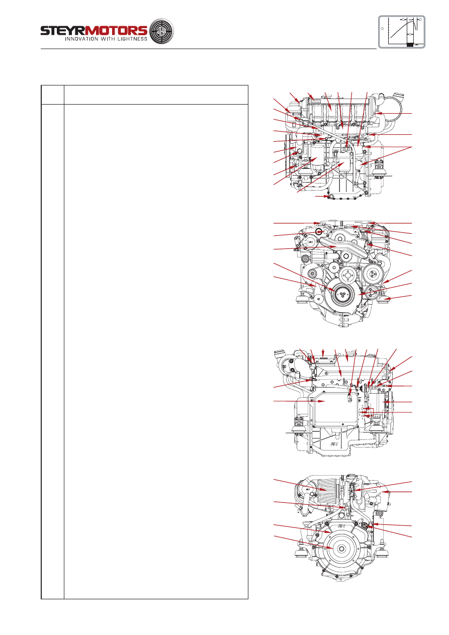
47
Overview for all STEYR 4 Cyl. Marine Engines
full load
speedrange
100%
90%
80%
70%
60%
50%
40%
30%
B
C
D
RPM
A
OUTPUT POWER
06001
19
18
17
16
15
14
13
12
11
1
5
1
4
7
8
2
3
6
10
9
06002
31
30
22
23
24
21
25
26
27
20
29
28
38
06003
44
43
1
36
15
34
40
41
1
39
32 33
37
42
35
06004
45
52
51
50
46
47
48
49
Item
Designation
1
Zinc Anode (4 Units)
2
Model and Serial Number
3
Intercooler
4
Fuel/Oil Cooler with Raw Water Drain Plug
5
Fuel Pump
6
Oil Seperator
7
Raw Water Drain Plug
8
Valve Crankshaft Housing Ventilation (only SOLAS)
9
Oil Drain Plug
10
Fuel Filter
11
Oil Filter
12
Hydraulic Pump
13
Raw Water Inlet Fitting
14
Raw Water Pump
15
Coolant Drain Plug (2 Units)
16
Engine Oilcooler
17
Oil Suction Pipe
18
Oil Dipstick
19
Hydraulic Oil Tank
20
Cooler Cap
21
Potentiometer Accelerator
22
Motor Oil Filler Cap
23
Boost Pressure Sensor
24
Potentiometer Rack Position
25
Drive Belt
26
Cover T-Belt, Lower
27
Engine Mount
28
Drive Belt Tensioner
29
Vibration Damper
30
Cover T-Belt, Upper
31
Engine Lifting Eye
32
Speed Sensor
33
Valve Cover
34
Heat Exchanger
35
Coolant Expansion Tank
36
Diagnostic Outlet
37
Inversion Switch (only for SOLAS)
38
Connector Instrument Panel
39
Coolant Temperature Sensor
40
Thermostat Housing
41
Alternator
42
Circuit Breakers
43
Engine Management System/Fuses
44
Exhaust Temperature Sensor
45
Air Filter
46
Turbo Charger
47
Exhaust Elbow
48
Starter Relais (Backside E-Box Ground Plate)
49
Starter Motor
50
Flywheel
51
Flywheel Housing
52
Oil Pressure Sensor
MO84K32 MO94K33
MO114K33 MO144V38
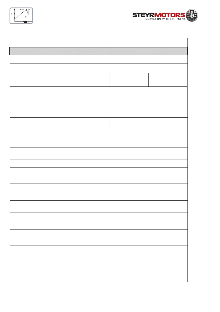
48
Technical Data
MO144M38
MO164M40
full load
speedrange
100%
90%
80%
70%
60%
50%
40%
30%
B
C
D
RPM
A
OUTPUT POWER
MAKE
STEYR M 14 TCAM
type
MO144M38
MO164M40
displacement
2133 cm³
piston displacement
85,0 x 94,0 mm
rated power acc. EN ISO 8665:2006
(crankshaft) KW / HP
106/144
120/163
number of cylinders
4-cylinder in-line engine (position of cyl. 1 at vibration damper side)
ignition order
1 - 3 - 4 - 2
sense of rotation, seen from front
right
compression ratio
17,5 : 1
full-load speed range (rpm)
3700 - 3900
3800 - 4000
idle speed
650 rpm. (adjustable)
injection
pump - nozzle with modelling needle control
and electronic control
fuel
acc. to CEC RF-03-A-84 (DIN EN 590) Cetan >49; diesel fuel
No. 2-D, temperature above -7°C; No.1-D, temperature below -7°C
fuel filter
P/No. 2203710/0
fuel filter location
intake-sided
air filter
P/No. 2178992/0
oil pressure above 2000 rpm.
400 - 700 kPa (58 - 101 PSI) microprocessor controlled
filling capacity motor oil
approx. 8,0 l engine housing (incl. approx. 1 l oil filter contents)
specification motor oil
SAE 5W-50/ACEA B4-02/API CF or 10W-40/ACEA E4, E5,
E7/API CF P/N0. Z010058/0
oil and oil filter change intervals*)
every 150 operating hours and/or once per season
oil filter
P/No. 2178582/1
oil filter location
pressure-sided
electric charging system
14 V / 90 A alternator with transistorized voltage regulator
cooling system
dual cooling circuit; thermostat-controlled, pressurized cooling
circuit; circulating pump with heat exchanger on engine; governor
pump, external raw water circuit to heat exchanger
coolant capacity
11,5 liters
coolant
STEYR MOTORS engine coolant - 36 C°
P/No. Z011785/0
*)
extended periods to be evaluated upon application and type of usage
STEYR MOTORS GmbH. reserves the right to make changes without notice or obligations.
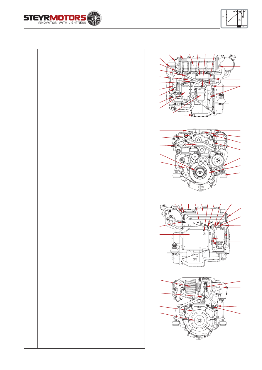
49
Overview for all STEYR 4 Cyl. Marine Engines
MO144M38
MO184V40
full load
speedrange
100%
90%
80%
70%
60%
50%
40%
30%
B
C
D
RPM
A
OUTPUT POWER
06001
19
18
17
16
15
14
13
12
11
1
5
1
4
7
8
2
3
6
10
9
06036
31
30
22
23
24
21
25
26
27
20
29
28
38
06003
44
43
1
36
15
34
40
41
1
39
32 33
37
42
35
06004
45
52
51
50
46
47
48
49
Item
Designation
1
Zinc Anode (4 Units)
2
Model and Serial Number
3
Intercooler
4
Fuel/Oil Cooler with Raw Water Drain Plug
5
Fuel Pump
6
Oil Seperator
7
Raw Water Drain Plug
8
Valve Crankshaft Housing Ventilation (only SOLAS)
9
Oil Drain Plug
10
Fuel Filter
11
Oil Filter
12
Hydraulic Pump
13
Raw Water Inlet Fitting
14
Raw Water Pump
15
Coolant Drain Plug (2 Units)
16
Engine Oilcooler
17
Oil Suction Pipe
18
Oil Dipstick
19
Hydraulic Oil Tank
20
Cooler Cap
21
Potentiometer Accelerator
22
Motor Oil Filler Cap
23
Boost Pressure Sensor
24
Potentiometer Rack Position
25
Drive Belt
26
Cover T-Belt, Lower
27
Engine Mount
28
Drive Belt Tensioner
29
Vibration Damper
30
Cover T-Belt, Upper
31
Engine Lifting Eye
32
Speed Sensor
33
Valve Cover
34
Heat Exchanger
35
Coolant Expansion Tank
36
Diagnostic Outlet
37
Inversion Switch (only for SOLAS)
38
Connector Instrument Panel
39
Coolant Temperature Sensor
40
Thermostat Housing
41
Alternator
42
Circuit Breakers
43
Engine Management System/Fuses
44
Exhaust Temperature Sensor
45
Air Filter
46
Turbo Charger
47
Exhaust Elbow
48
Starter Relais (Backside E-Box Ground Plate)
49
Starter Motor
50
Flywheel
51
Flywheel Housing
52
Oil Pressure Sensor
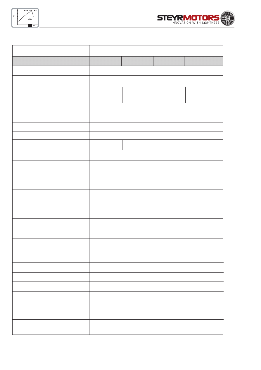
50
MO126M28 MO166K28
MO196K35 MO236K42
full load
speedrange
100%
90%
80%
70%
60%
50%
40%
30%
B
C
D
RPM
A
OUTPUT POWER
Technical Data
MAKE
STEYR M 16 TCM, TCAM
type
MO126M28 MO166K28
MO196K35
MO236K42
displacement
3200 cm³
piston displacement
85,0 x 94,0 mm
rated power acc. EN ISO 8665:2006
(crankshaft) KW / HP
90/120
120/163
140/190
170/230
number of cylinders
6-cylinder in-line engine (position of cyl. 1 at vibration damper side)
ignition order
1 - 5 - 3 - 6 -2 - 4
sense of rotation, seen from front
right
compression ratio
17,5 : 1
full-load speed range (rpm)
2600 - 2800 2600 - 2800
3300 - 3500 4000 - 4300
idle speed
630 rpm. (adjustable)
injection
pump - nozzle with modelling needle control
and electronic control
fuel
acc. to CEC RF-03-A-84 (DIN EN 590) Cetan >49; diesel fuel
No. 2-D, temperature above -7°C; No.1-D, temperature below -7°C
fuel filter
P/No. 2177745/1
fuel filter location
suction-sided
air filter
MO126 - P/No. 2178992/0; all other 6 Cyl. - P/N 2178992/1
oil pressure above 2000 rpm.
400 - 700 kPa (58 - 101 PSI) microprocessor controlled
filling capacity motor oil
approx. 10,0 l engine housing (incl. approx. 1 l oil filter contents)
specification motor oil
SAE 5W-50/ACEA B4-02/API CF or 10W-40/ACEA E4, E5,
E7/API CF P/N0. Z010058/0
oil and oil filter change intervals*)
every 150 operating hours and/or once per season
oil filter
P/No. 2178582/1
oil filter location
suction-sided
electric charging system
14 V / 90 A alternator with transistorized voltage regulator
cooling system
dual cooling circuit; thermostat-controlled, pressurized cooling
circuit; circulating pump with heat exchanger on engine; governor
pump, external raw water circuit to heat exchanger
coolant capacity
13,2 liters
coolant
STEYR MOTORS engine coolant - 36 C°
P/No. Z011785/0
*)
extended periods to be evaluated upon application and type of usage
STEYR MOTORS GmbH. reserves the right to make changes without notice or obligations.
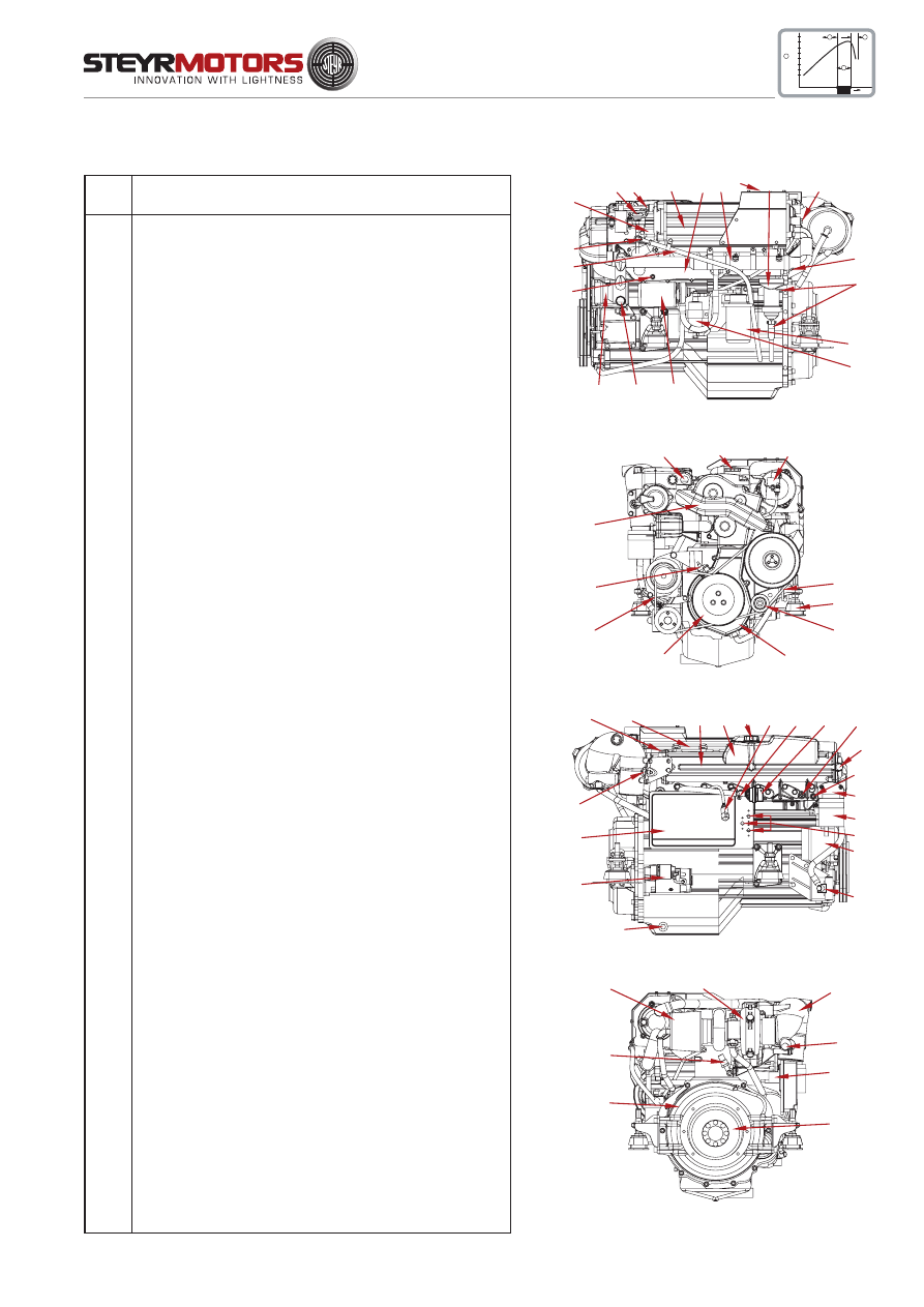
51
Overview STEYR MO126M28, MO166K28, MO196K35, MO236K42
MO126M28 MO166K28
MO196K35 MO236K42
full load
speedrange
100%
90%
80%
70%
60%
50%
40%
30%
B
C
D
RPM
A
OUTPUT POWER
06032
1
4
2
3
6
7
2
8
9
10
11
12
13
14
15
16
17
18
5
06033
19
20
21
22
23
24
25
26
27
28
29
06034
2
30
31 32 33 34 35 36 37
2
15
38
39
40
41
42
43
44
45
46
06035
47
48
49
2
50
51
52
53
Item
Designation
1
Boost Pressure Sensor
2
Zinc Anode (5 Units)
3
Intercooler
4
Fuel- / Hydr. Oil Cooler
5
Engine Oilcooler
6
Model and Serial Number
7
Oil Seperator
8
Raw Water Drain Plug
9
Valve Crankshaft Housing Ventilation (only SOLAS)
10
Fuel Filter
11
Fuel Pump
12
Oil Filter
13
Raw Water Inlet Fitting
14
Raw Water Pump
15
Coolant Drain Plug (2 Units)
16
Oil Suction Pipe
17
Oil Dipstick
18
Potentiometer Rack Position
19
Engine Lifting Eye
20
Motor Oil Filler Cap
21
Potentiometer Accelerator
22
Drive Belt, Raw Water Pump
23
Engine Mount
24
Drive Belt Tensioner
25
Cover T-Belt, Lower
26
Vibration Damper
27
Drive Belt, Alternator & Hydr: Pump
28
Speed Sensor
29
Cover T-Belt, Upper
30
Valve Cover
31
Heat Exchanger
32
Coolant Expansion Tank
33
Cooler Cap
34
Diagnostic Outlet
35
Inversion Switch (only for SOLAS)
36
Connector Instrument Panel
37
Coolant Temperature Sensor
38
Thermostat Housing
39
Hydraulic Oil Tank
40
Circuit Breakers
41
Alternator
42
Hydraulic Pump
43
Oil Drain Plug
44
Starter Motor
45
Engine Management System/Fuses
46
Exhaust Temperature Sensor
47
Air Filter
48
Turbo Charger
49
Exhaust Elbow
50
Starter Relais (Backside E-Box Ground Plate)
51
Flywheel
52
Flywheel Housing
53
Oil Pressure Sensor
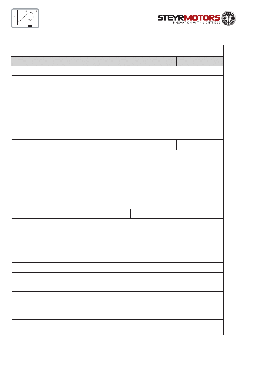
52
Technical Data
MO256K43
MO256H45
full load
speedrange
100%
90%
80%
70%
60%
50%
40%
30%
B
C
D
RPM
A
OUTPUT POWER
MAKE
STEYR M 16 TCAM
type
MO256K43
MO256H45
displacement
3200 cm³
piston displacement
85,0 x 94,0 mm
rated power acc. EN ISO 8665:2006
(crankshaft) KW / HP
184/250
184/250
number of cylinders
6-cylinder in-line engine (position of cyl. 1 at vibration damper side)
ignition order
1 - 5 - 3 - 6 -2 - 4
sense of rotation, seen from front
right
compression ratio
17,5 : 1
full-load speed range (rpm)
4000 - 4300
4000 - 4500
idle speed
630 rpm. (adjustable)
injection
pump - nozzle with modelling needle control
and electronic control
fuel
acc. to CEC RF-03-A-84 (DIN EN 590) Cetan >49; diesel fuel
No. 2-D, temperature above -7°C; No.1-D, temperature below -7°C
fuel filter
P/No. 2178992/1
fuel filter location
suction-sided
air filter
P/No. 2178992/0 P/No.2178992/1
oil pressure above 2000 rpm.
400 - 700 kPa (58 - 101 PSI) microprocessor controlled
filling capacity motor oil
approx. 10,0 l engine housing (incl. approx. 1 l oil filter contents)
specification motor oil
SAE 5W-50/ACEA B4-02/API CF or 10W-40/ACEA E4, E5,
E7/API CF P/N0. Z010058/0
oil and oil filter change intervals*)
every 150 operating hours and/or once per season
oil filter
P/No. 2178582/1
oil filter location
suction-sided
electric charging system
14 V / 90 A alternator with transistorized voltage regulator
cooling system
dual cooling circuit; thermostat-controlled, pressurized cooling
circuit; circulating pump with heat exchanger on engine; governor
pump, external raw water circuit to heat exchanger
coolant capacity
13,2 liters
coolant
STEYR MOTORS engine coolant - 36 C°
P/No. Z011785/0
*)
extended periods to be evaluated upon application and type of usage
STEYR MOTORS GmbH. reserves the right to make changes without notice or obligations.

53
Overview STEYR MO256K43, MO256H45
MO256K43
MO256H45
full load
speedrange
100%
90%
80%
70%
60%
50%
40%
30%
B
C
D
RPM
A
OUTPUT POWER
06028
1
4
2
3
5
6
2
7
8
9
10
11
12
13
14
15
16
17
06029
18
19
20
21
22
23
24
25
26
27
28
06030
2
29
30 31 32 33 34 35 36
2
14
37
38
39
40
41
42
43
44
45
06031
46
47
48
2
49
50
51
52
Item
Designation
1
Boost Pressure Sensor
2
Zinc Anode (5 Units)
3
Intercooler
4
Engine Oil / Fuel / Hydr. Oil Cooler
5
Model and Serial Number
6
Oil Seperator
7
Raw Water Drain Plug
8
Valve Crankshaft Housing Ventilation (only
SOLAS)
9
Fuel Filter
10
Fuel Pump
11
Oil Filter
12
Raw Water Inlet Fitting
13
Raw Water Pump
14
Coolant Drain Plug (2 Units)
15
Oil Suction Pipe
16
Oil Dipstick
17
Potentiometer Rack Position
18
Engine Lifting Eye
19
Motor Oil Filler Cap
20
Potentiometer Accelerator
21
Drive Belt, Raw Water Pump
22
Engine Mount
23
Drive Belt Tensioner
24
Cover T-Belt, Lower
25
Vibration Damper
26
Drive Belt, Alternator & Hydr: Pump
27
Speed Sensor
28
Cover T-Belt, Upper
29
Valve Cover
30
Heat Exchanger
31
Coolant Expansion Tank
32
Cooler Cap
33
Diagnostic Outlet
34
Inversion Switch (only for SOLAS)
35
Connector Instrument Panel
36
Coolant Temperature Sensor
37
Thermostat Housing
38
Hydraulic Oil Tank
39
Circuit Breakers
40
Alternator
41
Hydraulic Pump
42
Oil Drain Plug
43
Starter Motor
44
Engine Management System/Fuses
45
Exhaust Temperature Sensor
46
Air Filter
47
Turbo Charger
48
Exhaust Elbow
49
Starter Relais (Backside E-Box Ground Plate)
50
Flywheel
51
Flywheel Housing
52
Oil Pressure Sensor

54
full load
speedrange
100%
90%
80%
70%
60%
50%
40%
30%
B
C
D
RPM
A
OUTPUT POWER

55
MAINTENANCE AND TROUBLE SHOOTING
Owner Service Log .................................................................................. 57
Service- and Maintenance Chart .............................................................. 58
Maintenance Log ...................................................................................... 60
Table - Error indication on instrument panel ............................................. 62
Table - Error Indication on instrument panel (for SOLAS only) ................ 64
Reading Error Codes ................................................................................ 66
Indication and Cancellation of memorized sensor and circuit faults ......... 67
Priciple failure code list ............................................................................. 68
Trouble Check chart ................................................................................. 70
Wiring harness ......................................................................................... 72
Wiring diagram / Marine base - 4/6 cyl. - 12V .......................................... 73
Wiring diagram / Marine - 4/6 cyl. - 2 pole - 12V (Option) ........................ 74
Wiring diagram / Marine 6 cyl. - 24V (Option) .......................................... 75
Wiring diagram / Marine - 6 cyl. - 2 pole - 24V - E - box extern ................ 76
Description - Wiring harness instrument panels 4/6 cyl. (current version) 78
Wiring diagram / instrument panel - 4/6 cyl. - 12V .................................... 79
Wiring diagram / instrument panel - 4/6 cyl. - 24V (Option) ...................... 80
Wiring diagram / instrument panel - 4/6 cyl. - SOLAS - 12V (Option) ....... 81
Wiring diagram / instrument panel - 4/6 cyl. - SOLAS - 24V (Option) ....... 82

56

57
Owner Service Log
FOREWORD
On receipt of your new STEYR Marine Engine, the authorised dealer has signed the pre-delivery coupon thus
confirming to have carried out a pre-delivery service according to the manufacturers specifications.
Future service requirements are indicated in this OWNER SERVICE LOG - booklet. When these services are carried
out, the STEYR Marine dealer will stamp the respective stubs. This servicing will assist in maintaining the value and
satisfactory operation of your STEYR Marine Engine.
It lies in the owner's interest that for maintaining warranty and best performance of his STEYR Marine Engine he always
insists on the sole utilization of STEYR - ORIGINAL replacement parts, operational fluids and lubricants as well as
STEYR´S proved service procedures!
It is important that you study this booklet carefully as it will assist you in achieving satisfaction from your STEYR Marine
Engine. Please retain this manual in the boat as it MUST be presented to the STEYR Marine dealer whenever you
require WARRANTY SERVICE.
IMPORTANT NOTE:
This manual contains all service activities required for your engine. Checks and maintenance for the other parts
of a complete drive system still need to be completed. Any such procedures are to be found in separate,
attached booklet(s) of the individual manufacturer's literature provided with the gearbox or similar drive
components.
Whenever this manual refers to components like Manual Operation, Hydraulic Pump, etc., such instructions
only apply where applicable since they are not used on every engine model.
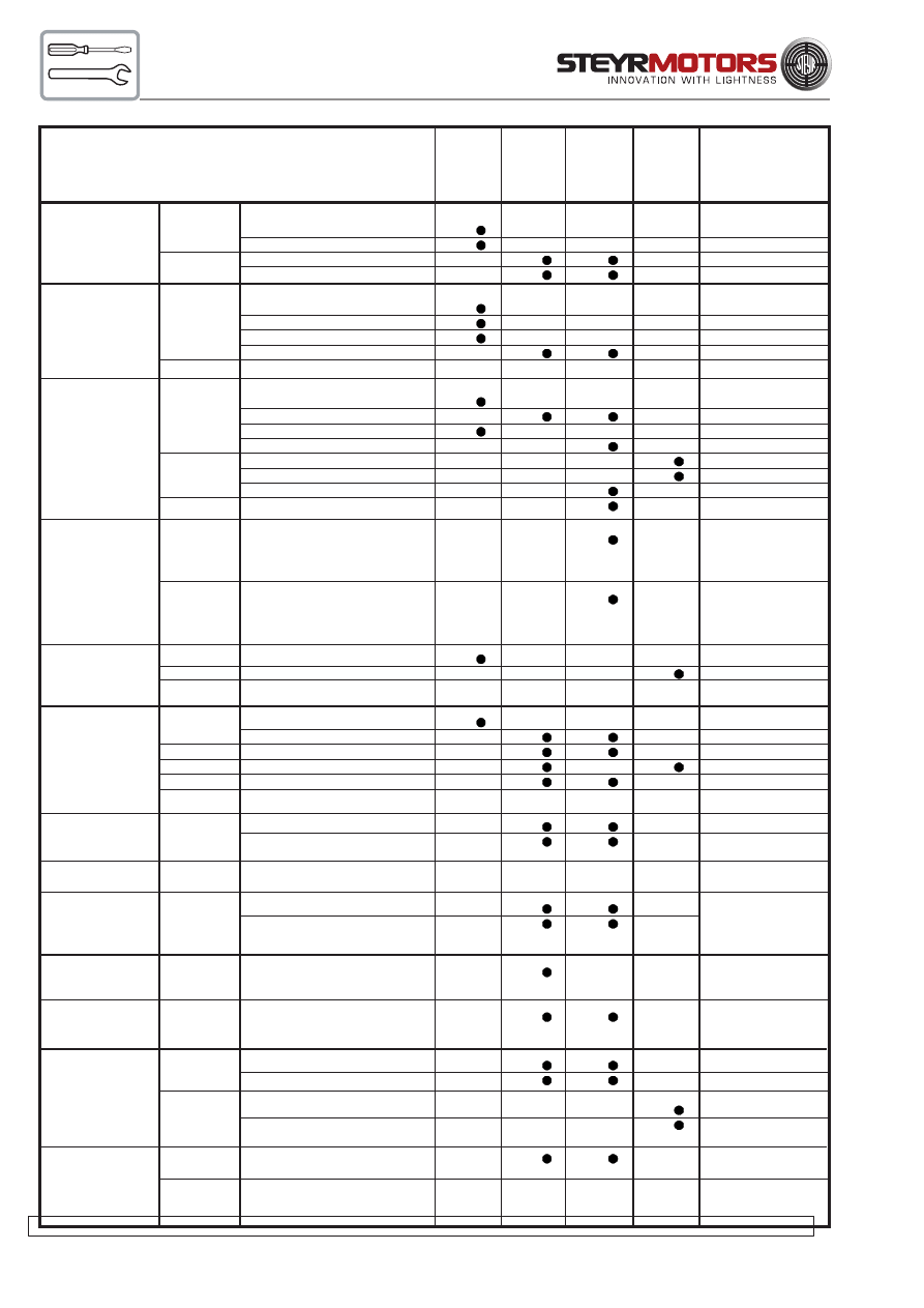
58
ENGINE
check
- for leakage
LUBRICATION
- oil level
change
- oil filter
- motor oil
ENGINE
check
- for leakage
COOLING
- fluid level
SYSTEM
- hoses, hose clamps
- antifreeze temperature condition
change
- antifreeze*)
every 24 month
RAW WATER
check
- hoses, hose clamps
SYSTEM
- zinc anodes
- raw water pump V-belt
- impeller
change
- raw water pump V-belt*)
if required
- impeller*)
if required
- zinc anodes*)
if corroded > 50%
preserve
- raw water circuit*)
after season
RAW WATER
check
- raw water passages*)
clean out desposits
COOLER
(OIL-FUEL-
in pipelines
AUX.LUBRICANT)
for 246/256
change
- zinc anodes*)
required if more
and 266 only
than 50% material
corroded
AIR
check
- contamination
FILTER
change
- air filter element
preserve
after season
FUEL
check
- for leakage
SYSTEM
- hoses
drain
- addtiional fuel filter
change
- fuel filter
check
- additional fuel filter
preserve
- fuel system*)
after season
BATTERY
check
- acid level
- densitiy
ELECTRONICS
check
- connections*)
after season
ELECTRICAL
check
- connections
tighten loose con-
EQUIPMENT
- insulation
nections. Renew
cables, if required.
INVERSION
check
- switch*)
every 50 hours
SWITCH (Solas only)
or every 6 months
DRIVING
re-center
- driving unit*)
see manufacturer's
SYSTEM
specifications
V-BELT
check
- generator & impeller pump
adjust tension
- power-steering
adjust tension
for all 6 cyl.
change
- generator*)
if required
models
- power-steering*)
if required
POLY - V -
check
- belt, pulleys and tighteners
BELT
for wear
change
- Poly -V-belt
every 1050 hours or
for all 4 cyl.
every 48 months
models
after first
50 hours
or 6
months
*) notes
daily
every
150 h.
or 12
months
every
300 h.
or 24
months
Service- and Maintenance Schedule
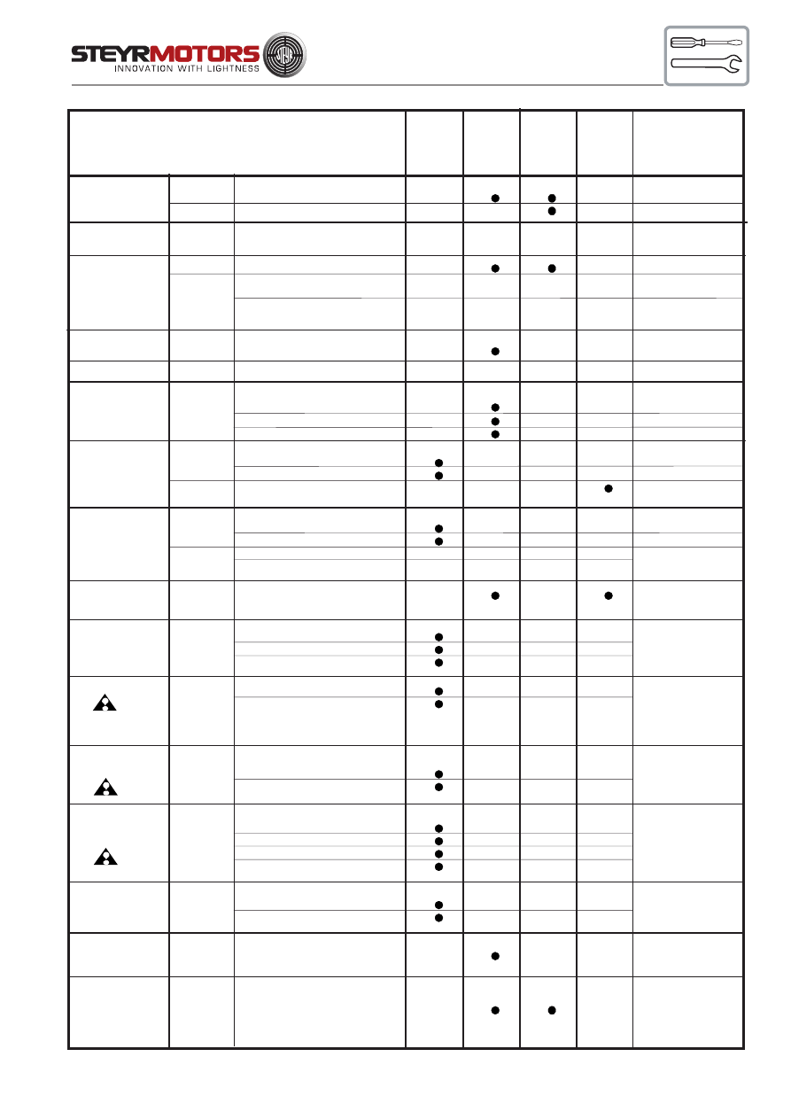
59
TIMING
check
- belt tension
BELT
change
- timing belt*)
every 1500 h. or
every 48 months
- water pump, tensioner
every 3000 h. or
every 48 months
VALVES
check
- valve clearance*)
every 750 hours
ENGINE TIMING
check
- set timing
every 750 hours
UNIT INJECTOR
- set levers*)
every 750 hours
check
- set point
every 750 hours
- tighten torque
every 750 hours
SERVO
check
- oil level
PUMP
- for leakage
change
- hydraulic oil (ATF) *)
every 750 h. or
every 24 months
after first
50 hours
or 6
months
*) notes
daily
every
150 h.
or 12
months
every
300 h.
or 24
months
Service- and Maintenance Schedule
GEARBOX-
check
- oil level
STERNDRIVE
- for leakage
change
- gear oil (ATF) *)
see manufacturer's
- oil filter
specifications
FRONT VIBRA-
check
- torque
TION DAMPER
ENGINE COM-
check for
- leakage -water
repair or consult
PARTMENT AND
-fuel
your STEYR
BILGE
-exhaust gas
Marine dealer
SHIFTING
check
- smooth action
If required, to be
- adjustment
replaced by your
STEYR Marine
Dealer.
STEERING
check
- lubrication
see manufacturer´s
- oil level
specification
SAFETY
check
- remote control
local rules
EQUIPMENT
- emergency cutout
and consultation
- completeness
of your STEYR
- condition
Marine Dealer
SHAFT BEARING
check
- lubrication
consult STEYR
GLAND
- sealing
Marine Dealer
ENGINE MOUNT
check
- torque*)
every 750 hours
SCREWS
WARNING
check
- function
DEVICE
POLY - V - BELT
check
TENSION
lubricate
GLOW PLUGS
change
- plugs*)
every 1500 h. or
every 48 months
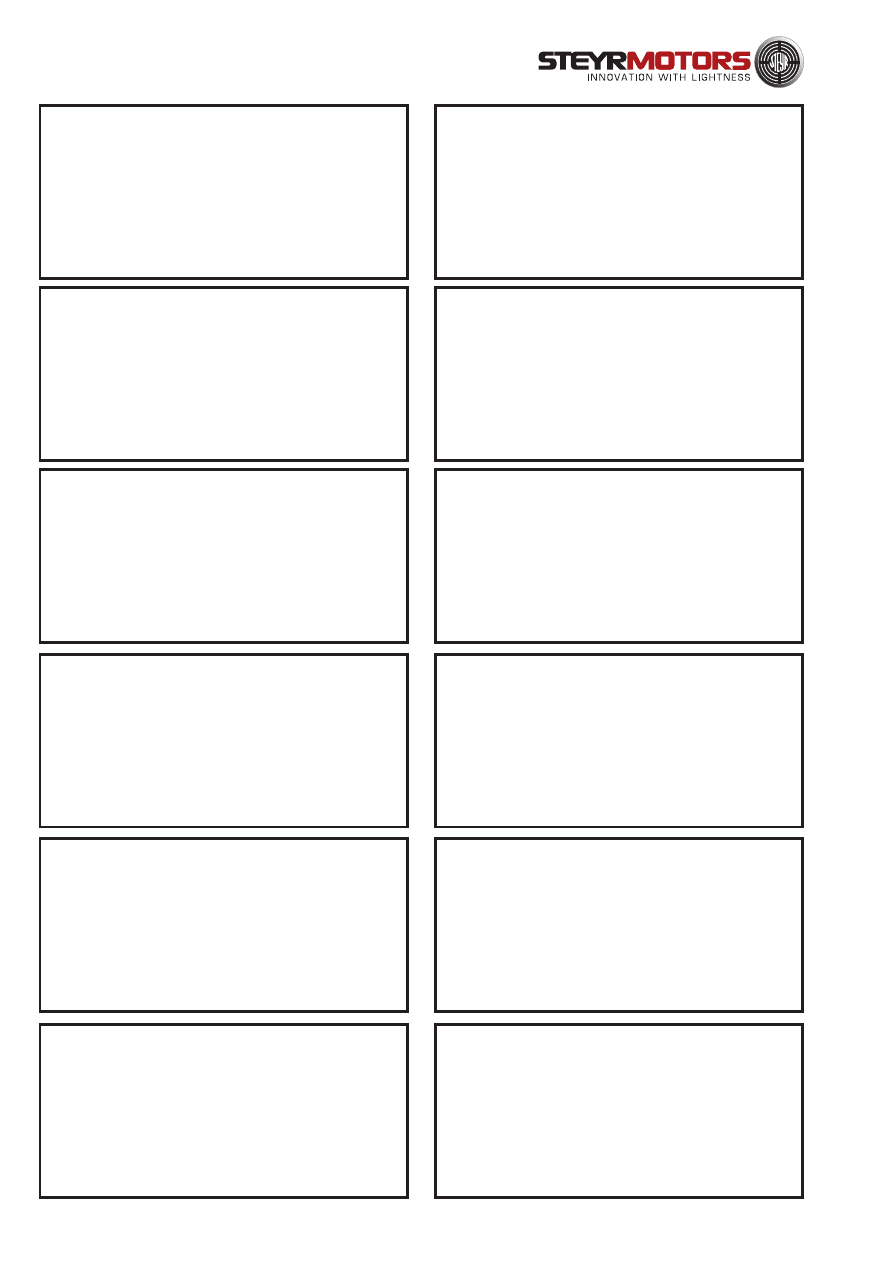
60
Commissioning
Made by:
Date:
50 h Service
Made by:
Date:
150 h Service
Made by:
Date:
300 h Service
Made by:
Date:
450 h Service
Made by:
Date:
600 h Service
Made by:
Date:
750 h Service
Made by:
Date:
900 h Service
Made by:
Date:
1050 h Service
Made by:
Date:
1200 h Service
Made by:
Date:
1350 h Service
Made by:
Date:
1500 h Service
Made by:
Date:
MAINTENANCE LOG
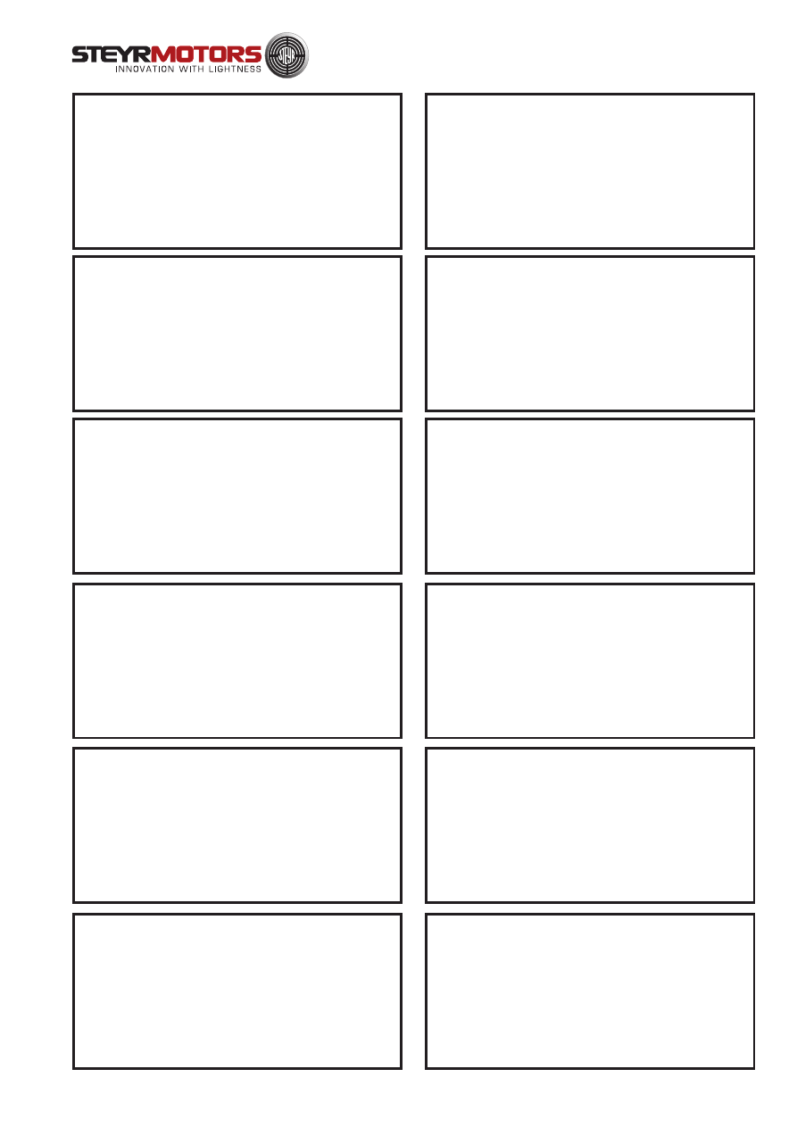
61
1650 h Service
Made by:
Date:
1800 h Service
Made by:
Date:
1950 h Service
Made by:
Date:
2100 h Service
Made by:
Date:
2250 h Service
Made by:
Date:
2400 h Service
Made by:
2550 h Service
Made by:
Date:
2700 h Service
Made by:
Date:
2850 h Service
Made by:
Date:
3000 h Service
Made by:
Date:
3150 h Service
Made by:
Date:
3300 h Service
Made by:
Date:
MAINTENANCE LOG
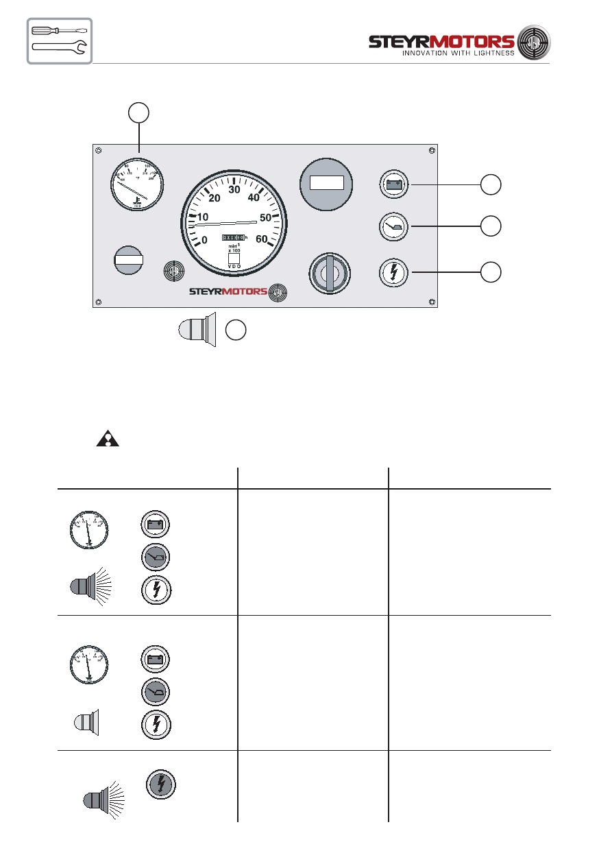
62
Table - Error Indication on Instrument Panel
A
C
D
E
B
A
temperature gauge - coolant
D
combined light preheating control &
B
audible warner
warning light engine oil pressure
C
warning light - battery charge
E
warning light check
engine
Operating condition:
During normale engine operation, or indication in case of sensor defect while
ignition is switched ON.
Event:
Speed resp. performance limitation during engine operation
80° - 90°C
ON
OFF
ON
OFF
Fault
oil pressure below min.
limit
Remarks
check oil level,
contact authorized
workshop
Indication status
80° - 90°C
OFF
OFF
OFF
FLASHING
(1x per sec.)
fault oil pressure
sensor or
sensor connection
check oil level,
contact authorized
workshop
reduce throttle position
until light goes OFF
(indication during first 2
hours of operation)
ON
engine overload during
break-in period
NOTE: (see page 18) check engine
light
OPTIONAL
INSTRUMENT
OPTIONAL
INSTRUMENT
ON
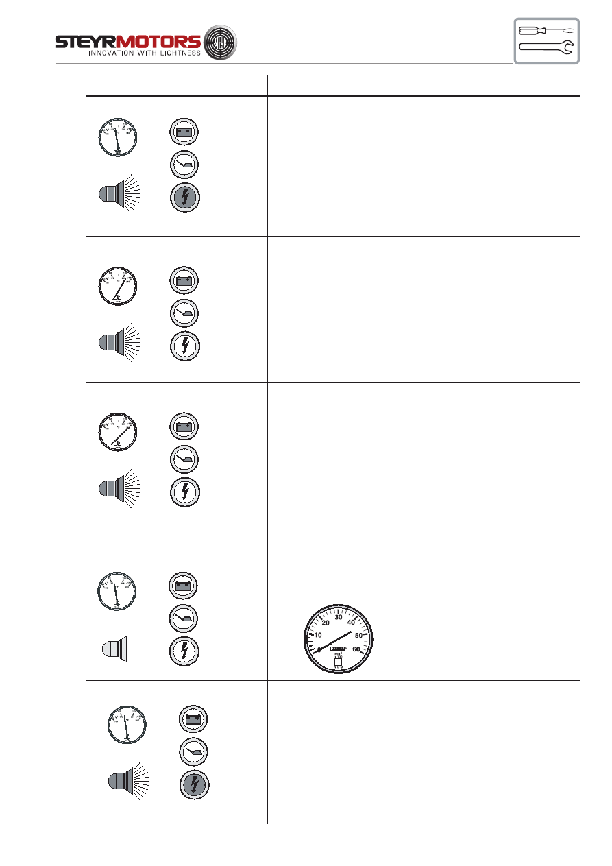
63
80° - 90°C
ON
(2x per sec.)
OFF
OFF
FLASHING
(2x per sec.)
Fault
high exhaust
temperature
(over 80° C)
or
defect exhaust
temperature sensor or
bad connection
Remarks
check raw water
system,
strainer, impeller pump
contact authorized
workshop
80° - 90°C
OFF
OFF
OFF
OFF
unstable idle speed,
no indication on
tachometer
defect speed sensor
or
sensor connection
contact authorized
workshop
high approx 105°C
ON
(2x per sec.)
OFF
OFF
OFF
engine coolant
temperature too high
after cooling down,
check engine coolant
level
contact authorized
workshop
120°C
ON
(2x per sec.)
OFF
OFF
OFF
defect engine coolant
sensor or
bad connection
after cooling down,
check engine coolant
level
contact authorized
workshop
Indication status
80° - 90°C
ON
OFF
OFF
ON
Trouble in governing loop,
involved components:
control solenoid, rack,
control gear of
unit injector,
rack potentiometer
contact authorized workshop
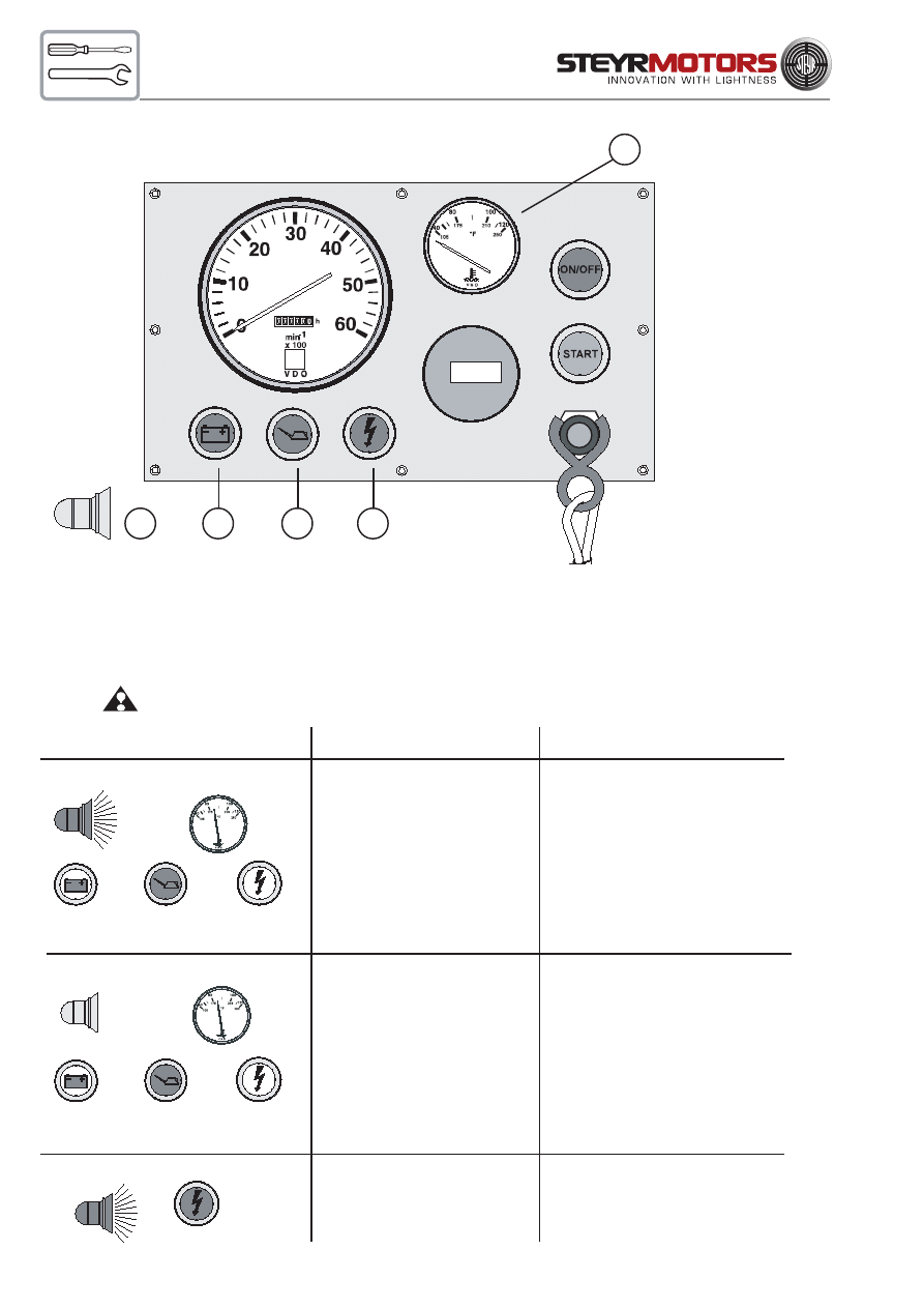
64
Table - Error Indication on Instrument Panel
(for SOLAS only)
C
B
A
D
E
A
temperature gauge - coolant
D
combined light preheating control &
B
audible warning device
warning light engine oil pressure
C
warning light - battery charge
E
warning light check engine
Operating condition:
During normal engine operation,
or indication in case of sensor defect while ignition is switched ON.
Event:
Speed resp. performance limitation during engine operation
80° - 90°C
ON
OFF
Fault
oil pressure below min.
limit
Remarks
check oil level
contact authorized
workshop
Indication status
OFF
ON
80° - 90°C
OFF
fault oil pressure
sensor or
sensor connection
check oil level
contact authorized
workshop
OFF
OFF
FLASHING
(1x per sek.)
ON
engine overload during
break-in period
NOTE: (see page 18) check engine
light
reduce throttle position until light
goes OFF (indication during first 2
hours of operation)
OPTIONAL
INSTRUMENT
BUKH STEYR SOLAS
ON
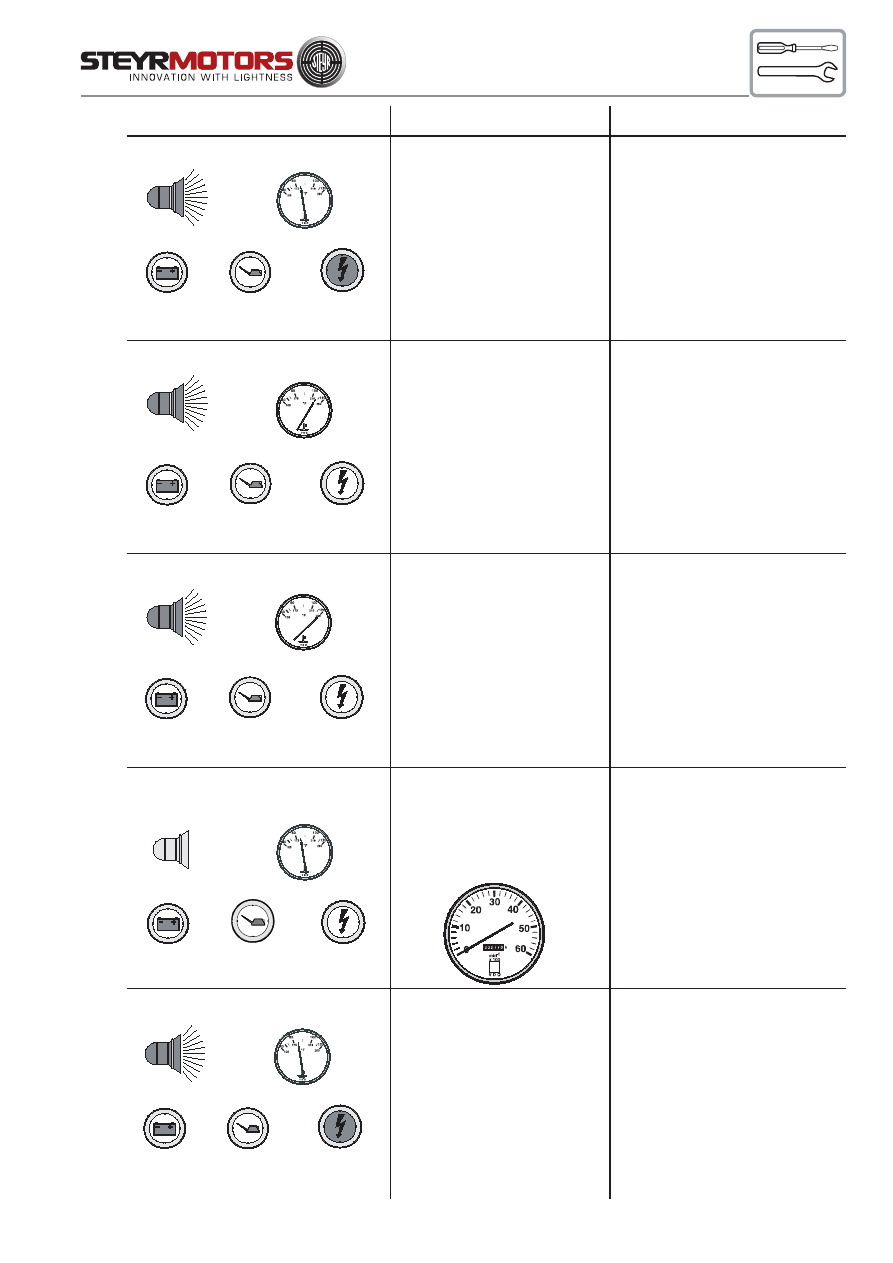
65
BUKH STEYR SOLAS
80° - 90°C
ON
(2x per sec.)
OFF
OFF
FLASHING
(2x per sec.)
80° - 90°C
OFF
high approx 105°C
ON
(2x per sec.)
OFF
OFF
OFF
120°C
ON
(2x per sec.)
OFF
OFF
OFF
OFF
OFF
OFF
Fault
high exhaust
temperature
(over 80° C)
or
defect exhaust
temperature sensor or
bad connection
Remarks
check raw water
system,
strainer, impeller pump
contact authorized
workshop
unstable idle speed,
no indication on
tachometer
defect speed sensor
or
sensor connection
contact authorized
workshop
engine coolant
temperature too high
after cooling down,
check engine coolant
level
contact authorized
workshop
defect engine coolant
sensor or
bad connection
after cooling down,
check engine coolant
level
contact authorized
workshop
Indication status
Trouble in governing loop,
involved components:
control solenoid, rack,
control gear of
unit injector,
rack potentiometer
contact authorized
workshop
ON
OFF
OFF
ON
80° - 90°C
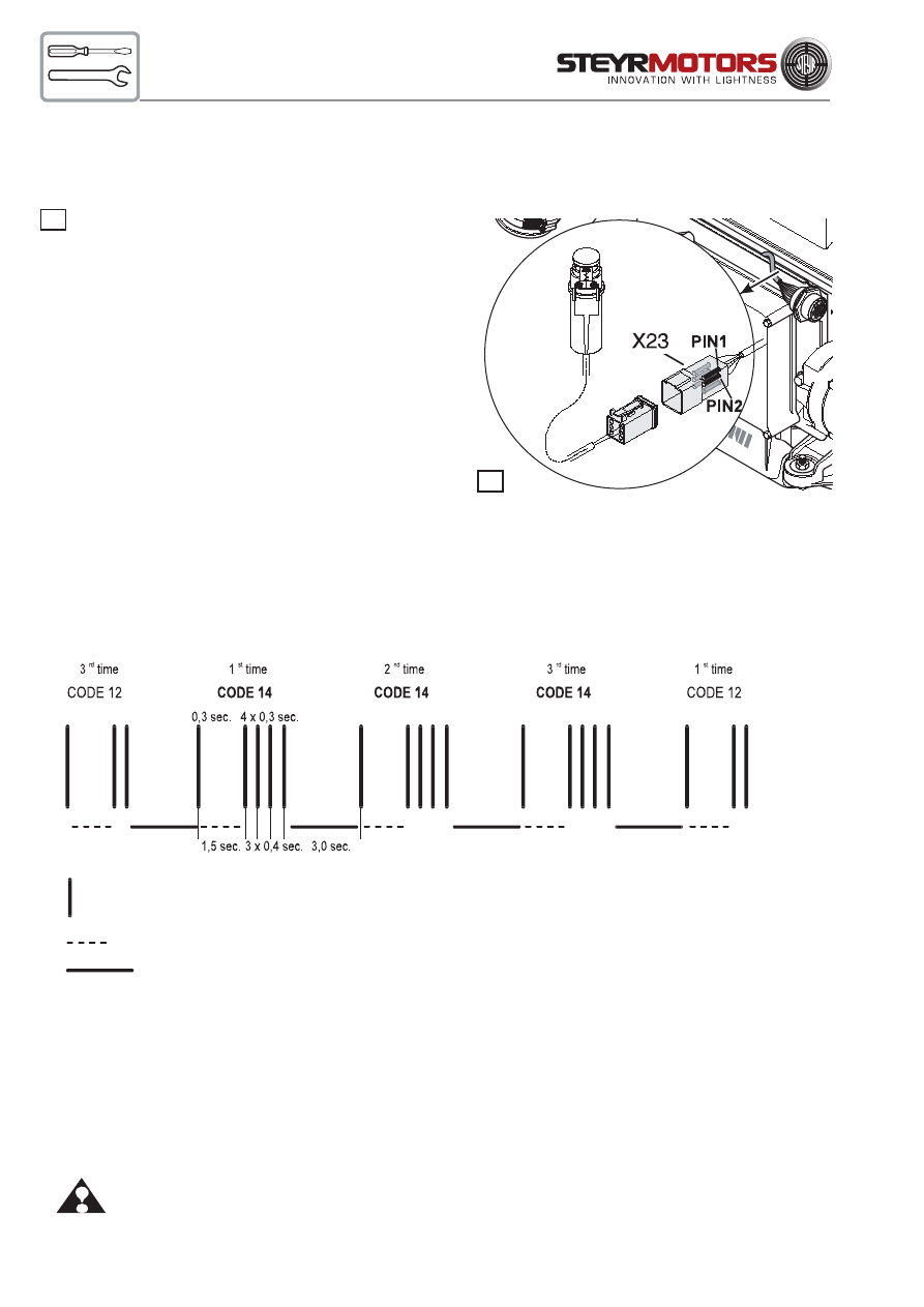
66
Reading Error Codes
Entering and reading of stored faults via Check Engine Lamp and Diagnostic Outlet Plug ( X 23 ):
Needed device:
Tool VR00135/1
( normally closed push button switch )
connected to Diagnostic Outlet Plug X23.
In case this tool is not available:
Connect temporarily Pin - Pos. 1 with Pin - Pos. 2
of Diagnostic Plug X 23
( before ignition is turned on at key switch )
Code indication and indication sequence:
After entering the error code indication modus the Engine
Management System will display a blink code at the Check Engine Light on the dash panel.
The blinking sequence will always begin and end with control code indication # 12. Each
ERROR
CODE
will be re-
peated 3 times to reassure your correct reading – see below bar code illustration.
Example sequence check engine light: Error code # 14
If more then one error code is stored in the Engine Management System the indication sequence will be continued
blinking additional stored error codes. To delete a memorized error code see description Indication and Cancella-
tion of memorized sensor and circuit faults.
For a description of the possible error codes refer to enclosed Table – Error Codes
ATTENTION: To exit from Error code indication. Tool VR00135/1 must be removed ( connection between Pin 1 to
Pin 2 opened ) before ignition is turned ON again.
18
18
Stroke = Check Engine Light illuminated for 0,3 sec. (Light Off - period within blink sequence 0,4 sec.)
Dashed Line = interruption within code indication 1,5 sec.
Solid Line = interval interruption between error code 3,0 sec.

67
Indication and Cancellation of memorised sensor and circuit faults
Selection and clearing of stored error codes:
Procedure:
*
Ignition — OFF
*
Connect Tool VR00135/1 to Diagnostic Outlet Plug ( X 23 )
*
Ignition — ON
Note: The program changes automatically to indication of error codes.
If no error code is stored, only repeating control code reading “ C
ODE
# 12 “ will be displayed.
Possible memorized codes are indicated as shown in the previous illustrated example ( blinking 3x
C
ODE
# 12 i. e. 3x
ERROR
CODE
# 14 etc. ) The sequence will be prolonged with additional codes if
more then one
ERROR
CODE
is stored.
See Table – E
RROR
CODES
for description
*
To delete a determined
ERROR
CODE
from the Engine Management System concentrate for the 3
rd
times flashing the desired
ERROR
CODE
. While this
ERROR
CODE
is displayed the third time the button (
Tool VR00135/1 ) must be pushed and kept in this position ( contact open ).
*
The indication on the Check Engine Light changes to a fast blinking of the lamp ( app. 4 times per
sec. ). During this rapid flashing light the push button must be released ( close contact after app. 2
sec.) to delete this
ERROR
CODE
.
Note: Any other
ERROR
CODE
have to be selected and cleared individually following the above men-
tioned procedure to delete a determined
ERROR
CODE
.
Note: An
ERROR
CODE
can only be deleted if no defect exists in this circuit. In case of a present active
failure, the
ERROR
CODE
keeps reappearing until the problem has been repaired and the circuit is
properly working again.
*
Disconnect Tool VR00135/1 from Diagnostic Outlet Plug ( X 23 ) to exit from error code display.
Note: Watch indication of the Check Engine Light and the Warning Horn after ignition contact. If all
ERROR
CODES
are deleted from the Engine Management System the indication resumes to 0.7 sec.
function test of Check Engine Light and the Warning Horn.
For additional details see Chart – Operating Conditions - Instrument panel.
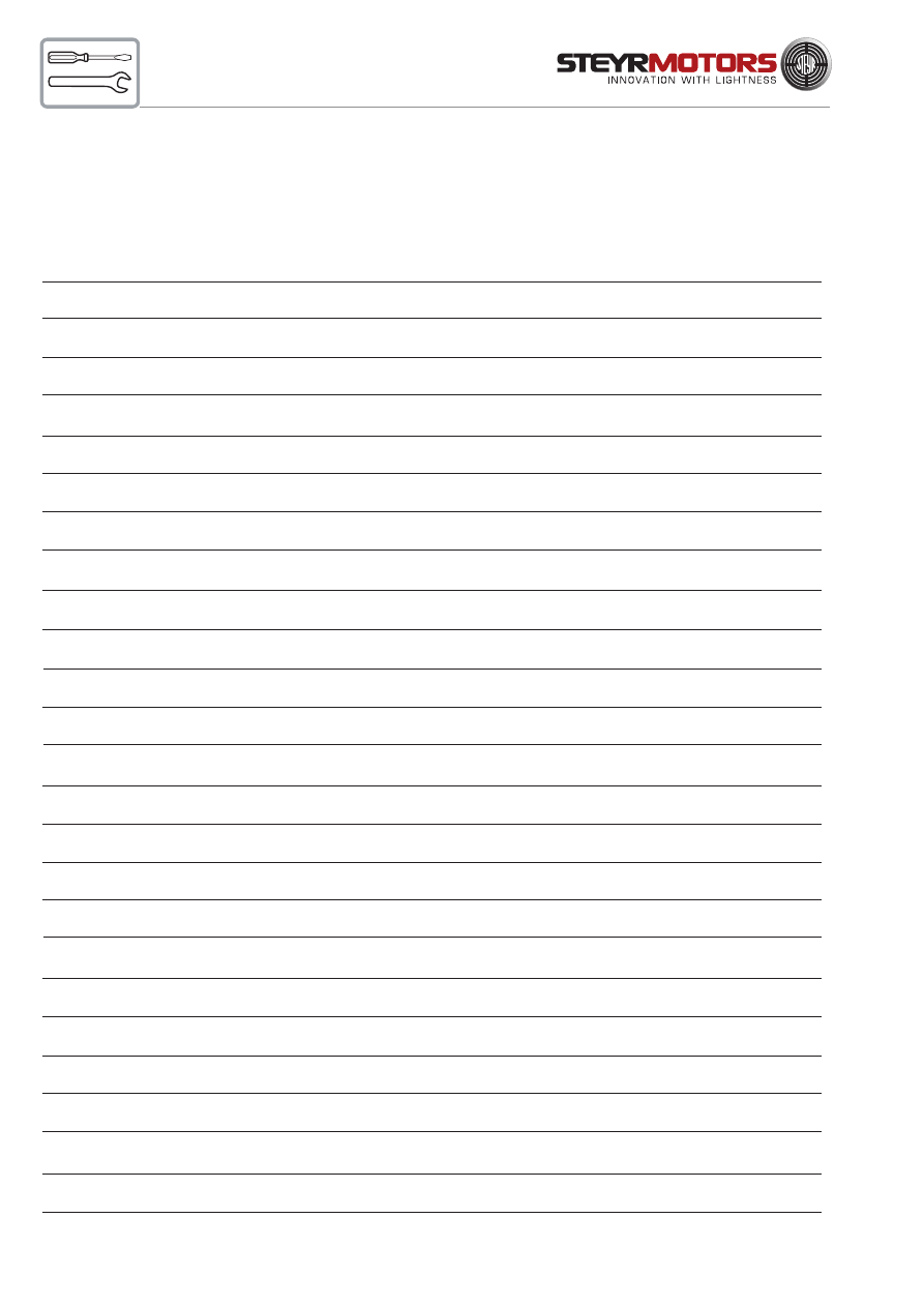
68
Principle failure code list
NOTE:
Some codes may not apply due to different application!
CODE
12
13
14
17
18
21
22
23
24
25
26
27
28
29
31
32
33
34
35
36
37
38
53
54
55
56
ABBREV.
Control code
LoMap
HiMap
LoEXH
HiEXH
LoECT
HiECT
LoPed1
HiPed1
LoVPWR
HiVPWR
LoVREF
HiVREF
PedS
LoLPS
HiLPS
LoPed2
HiPed2
LoRPos
HiRPos
LoLOP
HiLOP
N_RFI
BadSta
NoPuls
Srpos
REFER
TO
CIRCUIT
INVOLVED DEVICE
POSSIBLE CAUSE
X12/B12
X12/B12
X17/B17
X17/B17
X16/B16
X16/B16
X13/B13
X13/B13
F5/K27
F5/K27
X5/Z3
X5/Z1
X13/B13
X18/B18
X18/B18
X13/B13
X13/B13
X14/B14
X14/B14
X18/B18
X18/B18
X15/B15
M1-Pin50
X15/B15
Y14(B14)
boost pressure sensor
boost pressure sensor
air charge temp. sensor
air charge temp. sensor
water temp. sensor
water temp. sensor
potentiometer accelerator
potentiometer accelerator
main relay
main relay
module, connector
module, connector
accelerator potentiometer
lubricant pressure sensor
lubricant pressure sensor
potentiometer accelerator
potentiometer accelerator
rack position potentiometer
rack position potentiometer
lubricant pressure sensor
lubricant pressure sensor
RPM-sensor
K28 start assist relay
RPM-sensor
refer to setting rack pos.
this code is designated for beginning or end of loop
signal level too low (short circuit or missing contact)
signal level too high (missing connection)
signal level too low (short circuit or missing contact)
signal level too high (missing connection)
signal level too low (short circuit or missing contact)
signal level too high (missing connection)
signal level entry too low
signal level entry too high
low voltage supply to ECU, F5, K27
too high voltage on VPROT input
too low voltage on sensor supply, possible short circuit
too high voltage on sensor supply
defect on pedal safety switch, pin 1-2
signal level too low (short circuit or missing contact)
signal level too high (missing connection)
signal level too low
signal level too high (missing connection)
signal level too low (short circuit or missing contact)
signal level too high (missing connection)
signal level too low (short circuit)
signal level too high (missing connection)
radio interference / sensor input
no start signal from assist solenoid
no speed signal during crank
rack calibration bad/rack position outside tolerance field

69
CODE
57
99
161
162
164
165
167
168
177
178
181
182
186
187
188
193
194
195
201
202
203
251
252
253
254
255
ABBREV.
Rack0
FMSpwm
HiVTGc
LoVTGc
CELs
CELo
FPR_s
FPR_o
MR_s
MR_o
WarnLs
WarnLo
BadPos
HiFMSC
LoFMSc
VTG_Bad
GPR_s
GPR_o
HiTEMP
Lop
Manop
ITSL_Bad
ITV_LoCur
ITV_HiCur
SpvP_Bad
Spv_INI
REFER
TO
CIRCUIT
INVOLVED DEVICE
POSSIBLE CAUSE
Y14(B14)
X20/Y20
Y28
Y28
L2
L2
K24
K24
K27
K27
L3
L3
Y20
X20/X20
X20
Y28
K26
K26
--
--
--
B30
Y29
Y29
B30
B30
refer to setting rack pos.
actuator / solenoid
REA unit at turbo charger
REA unit at turbo charger
check engine lamp
check engine lamp
fuel pump relay
fuel pump relay
main relay
main relay
oil pressure lamp
oil pressure lamp
governor solenoid
governor solenoid
governor solenoid
REA unit at turbo charger
glow assist relay
glow assist relay
operation limit exceeded -
operation limit exceeded -
operation limit exceeded -
position sensor - ITD
proportional valve - ITD
proportional valve - ITD
position sensor or ITD
reference-position
bad rack zero position
defect in circuit of actuator turbo charger (short circuit)
defect in circuit of actuator turbo charger (missing connection)
Current limit exceeded (short circuit)
missing connection or bulb blown
Current limit exceeded in relay circuit (short circuit)
no current detected in relay circuit (disconnection)
no current detected in main relay circuit (short circuit)
no current detected in main relay circuit (disconnection)
Current limit exceeded (short circuit)
no current in circuit of oil pressure lamp
Nominal-actual value difference (rack pos. error, rack jammed)
defect in governor wire circuit (resistance too high)
defect in governor wire circuit (resistance too low)
defect in output circuit (short circuit or missing connection)
current limit exceeded in glow plug relay circuit (short circuit)
no current detected in glow plug relay circuit (disconnection)
engine was operated with too high coolant temperature
engine was operated with too low lubricant pressure
engine operated with manual movement of rack
signal level too low (short circuit) on injection timing sensor
defect in circuit of valve (no current flow)
defect in circuit of valve (current value too high)
commanded timing position can not be achieved
timing position calibration bad (position out of tolercance)
defect in governor solenoid wire circuit (Y20, main
relay K27-no frequency sent or govenor solenoid
circuit connected)
(bulb blown or missing connection)
engine overheated
lubricant pressure too low
rack position too high
sensor ITD
(sensor or injection timing device defect, eccenter
shaft jammed)
70
Trouble Check Chart
ATTENTION:
After following the “Action” described in chart, and before cranking the engine, make sure there
are no loose fuel connections. Make sure engine compartment is free of fuel vapours. Failure to
do so could result in fire.
SYMPTOM
POSSIBLE CAUSE
ACTION
Engine won’t start
1. No fuel in tank or shut-off valve
Fill tank or open valve.
closed.
2. Air leak in suction lines.
Bleed fuel system and check for leaks.
3. Fuel line plugged or pump
Fuel pump may be defective.
defective.
See your STEYR Marine dealer.
4. Poor fuel quality.
Replace fuel .
5. Water in fuel filter.
Replace or drain water from fuel filter.
Check fuel supply for water contamination. If water
is present, drain fuel tank and flush with fresh fuel.
6. System error or failure.
Check Engine Management System
display for service code.
7. Battery output insufficient
Charge or replace battery.
Only for SOLAS ==>
8. Inversion switch actuated
Cancelled by ignition "OFF - ON"
Starter won’t crank
1. Battery connections loose or
Check for loose connections
engine
corroded
and corrosions. Clean connections and
thighten.
2. Battery is dead
Check level of electrolyte and charge
battery.
3. Starter connections loose
Check connections and tighten.
If solenoid clicks when attempting to
start engine, see your STEYR Marine dealer.
4. Ignition switch
If inoperative, see your STEYR Marine dealer.
5. Fuse blown on panel
Check and replace if defect.
6. Starter auxiliary relay
Check terminal connection and function of relay.
Engine runs erratically 1. Water, air and/or dirt in fuel filter
Replace filter. Inspect fuel supply line.
2. Anti-siphon valve stuck
Clean and inspect or replace. (Tank)
3. Fuel pump
Check operation of pump.
Replace fuel pump.
See your STEYR Marine dealer.
71
Trouble Check Chart - Continued
SYMPTOM
POSSIBLE CAUSE
ACTION
Engine vibrates
Propeller condition
Check for bent, broken, or damaged propeller
Check for weeds on propeller or sterndrive
gearcase. Check for bent propeller shaft.
Unit injector
See your STEYR Marine dealer.
Engine runs but boat
Fouled propeller etc.
Check:
makes little or no
1. Propeller for weeds, remove
progress
as required.
2. Propeller for spun hub, repair
or replace.
3. Hull for excessive marine growth, clean
as required.
Performance loss
1. System error or failure.
Check: using diagnostics for errors or limitations.
Engine coolant temperature; audible and or visual
alarms.
2. Boat overloaded
Reduce load.
3. Boat trim
Distribute boat load evenly. Adjust trim.
4. Excessive water in bilge
Drain bilge.
5. Boat hull condition
See your STEYR Marine dealer.
6. Improper propeller selection
Select proper propeller pitch and diameter.
7. Fuel incorrect
Fill tank with correct fuel.
Check fuel filter and fuel flow condition.
8. Throttle not fully open
Check throttle command lever for
full travel.
9. Overheating
Check cooling system. Remove debris
from water intake. Check belt tension.
Check condition of impeller.
Check for clogged heat exchanger tubing
(in raw water circuit).
10. Air intake troubles
Check intake air filter.
Check ventilation of engine compartment.
Excessive free play in Steering cable loose
See your STEYR Marine dealer.
steering wheel
High shift effort
1. Remote control or transom
Replace and adjust.
bracket shift cable
See your STEYR Marine dealer.
2. Remote control binding
See your STEYR Marine dealer.
3. Engine / drive mechanism binding See your STEYR Marine dealer.
72
Cable numbers / principal functions:
15000-xx
ignition - positive
(from ignition switch)
15012-xx
+12 volt via main relay
and modulator unit A5
15100-xx
+5 volt supply voltage for sensors
30000-xx
battery-positive (not secured)
30012-xx
battery-positive (secured)
31000-xx
battery negative (GND)
31100-xx
Do not connect mass for sensors
with battery negative!
601xx-01
Sensor signal to modulator unit
A5 and/or instruments.
606xx-01
Exit from modulator unit A5
to display system (tachometer,
temperature display, ...)
Wiring harness
Designation
Component
Description
A5
E-Box
control unit
F1
fuse 50 A
main fuse
F2
fuse 50 A
glow plugs
F3
fuse 50 A
glow plugs
F4
fuse 5 A
permanent current modul and K27
F5
fuse 10 A
switched current for module (K27)
F6
fuse 10 A
fuel pump (K24)
F7
fuse 10 A
preheating - control circuit
G1
alternator
G2
battery
to be provided by customer
J1
plug 23--pole
connection engine cable - instrument cable
K24
relay
fuel pump
K26-1
relay
preheating - control circuit
K26-2
relay
preheating - load circuit
K27
relay
main circuit
K28
relay
start
M1
starter
M2
fuel pump
R10
glow pins
X2 (S2)
plug 2-pole
gears switch
X3 (S3)
plug 2-pole
inversion switch ( only SOLAS)
X5 (A5)
plug 35-pole
module
X12 (B12)
plug 3-pole
boost-pressure sensor
X13 (B13)
plug 5-pole
potentiometer accelerator
X14 (B14)
plug 3-pole
pot. rack position
X15(B15)
plug 3-pole
engine speed sensor
X16 B(16)
plug 2-pole
engine temperature sensor
X17 (B17)
plug 2-pole
exhaust gas temperature sensor
X18 (B18)
plug 3-pole
oil pressure sensor
X19 (B19)
plug 1-pole
oil pressure gauge (optional)
X20 (Y20)
plug 2-pole
control solenoid
X22 (B22)
without stop
trim sensor (optional)
X23
plug 6-pole
diagnosis
X26 (Y26)
plug 2-pole
disconnection blow-by (only SOLAS)
Z1
splice spot
earth connection sensor
Z2
splice spot
earth connection (31) on engine
Z3
splice spot
sensor supply +5V
Z4
splice spot
earth connection (31) on E-box plate
Z6
splice spot
shield speed sensor line
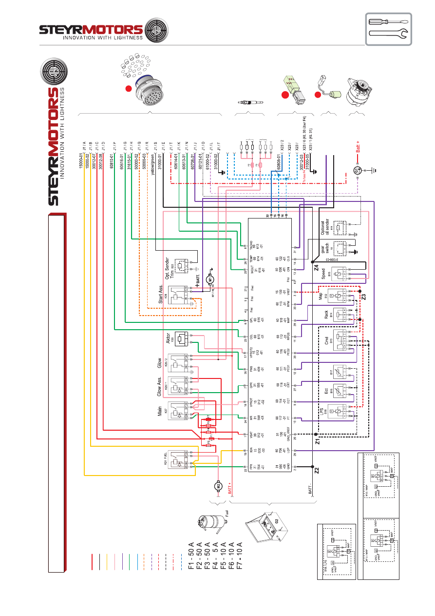
73
A
B
C
D
E
F
G
H
J
K
L M N O
P
Q
R
S
T
V
W
X
U
R
Q
B
A
J1
STARTER
X23
1 2 3
6 5 4
1
2
3
6
5
4
X3
CONNECTOR "A5" (ENGINE-CONTROL-UNIT)
EXT
J1 / U
J1 / V
60901-03
60900-03
60900-02
60901-02
5 CAN "H"
4 CAN "L"
X3/S3 Invers
X3/S3 Solas
60123-01
31000-1
1
D+ B+
Optional 24V DC
61001-02
WIRING DIAGRAM / MARINE BASE - 4/6 CYLINDER - 12V
Batt +
Batt -
Ign 15
Supplied by Relais
Sens ECU
Control ECU
DIAG
Start
Charge D+
Sens 5V
Sens -
B+ 24V
CAN
Z5
Z6
EXCEPTIONS: ONL
Y FOR
TYP:
MO
164M40
MO
174V40
MO
246K41
MO
256H45
MO
256K43
MO
266K43
A
31100-08
15100-05
601
10-01
60808-01 ISO
60900-01 CAN-H
60901-01 CAN-L
60 123 -01 WS
2179349/0-02-070118_tedoc
www
.steyr-motors.com
R10/5
R10/1
R10/2
R10/3
R10/4
R10/6
6 CYL.
6 CYL.
4 CYL.
4 CYL.
Wiring MAP
/
All engines before 2007
Wiring LPS /
All engines before 2007
A
31100-10
15100-07
601
17-01
31100-08
15100-05
601
10-01
ALL
ENGINE
TYPES WITH FOLLOWING EXCEPTIONS
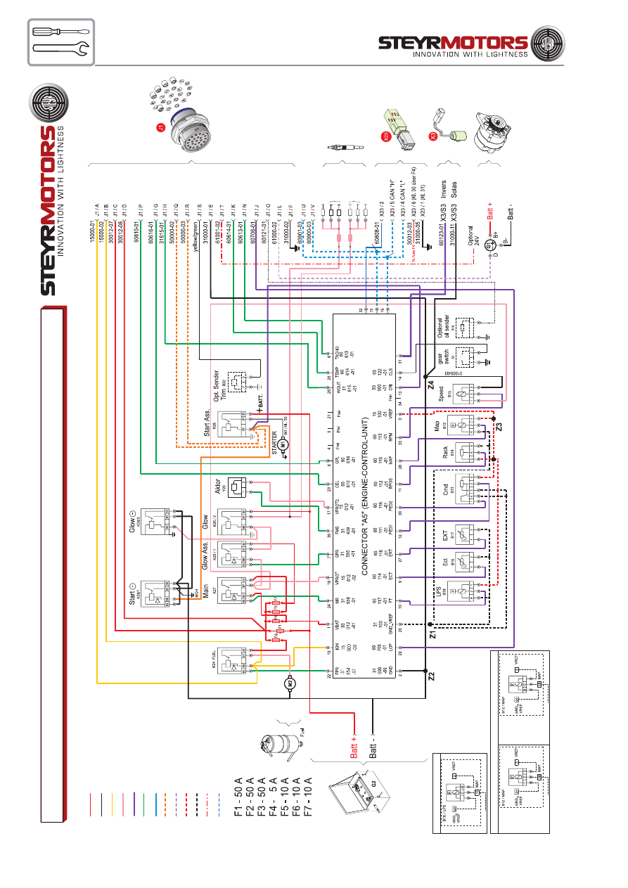
74
74
R10/5
R10/1
R10/2
R10/3
R10/4
R10/6
6 CYL.
6 CYL.
4 CYL.
4 CYL.
WIRING DIAGRAM / MARINE - 4/6 CYLINDER - 2-POLE - 12V (OPTION)
2179350/0-02-070118_tedoc
www
.steyr-motors.com
Z5
Z6
60900-02
60901-02
60808-01 ISO
60900-01 CAN-H
60901-01 CAN-L
60 123 -01 WS
Batt +
Batt -
Ign 15
Supplied by Relais
Sens ECU
Control ECU
DIAG
Start
Charge D+
Sens 5V
Sens -
B+ 24V
CAN
Wiring LPS /
All engines before 2007
A
31100-10
15100-07
601
17-01
EXCEPTIONS: ONL
Y FOR
TYP:
MO
164M40
MO
174V40
MO
246K41
MO
256H45
MO
256K43
MO
266K43
A
31100-08
15100-05
601
10-01
Wiring MAP
/
All engines before 2007
31100-08
15100-05
601
10-01
ALL
ENGINE
TYPES WITH FOLLOWING EXCEPTIONS
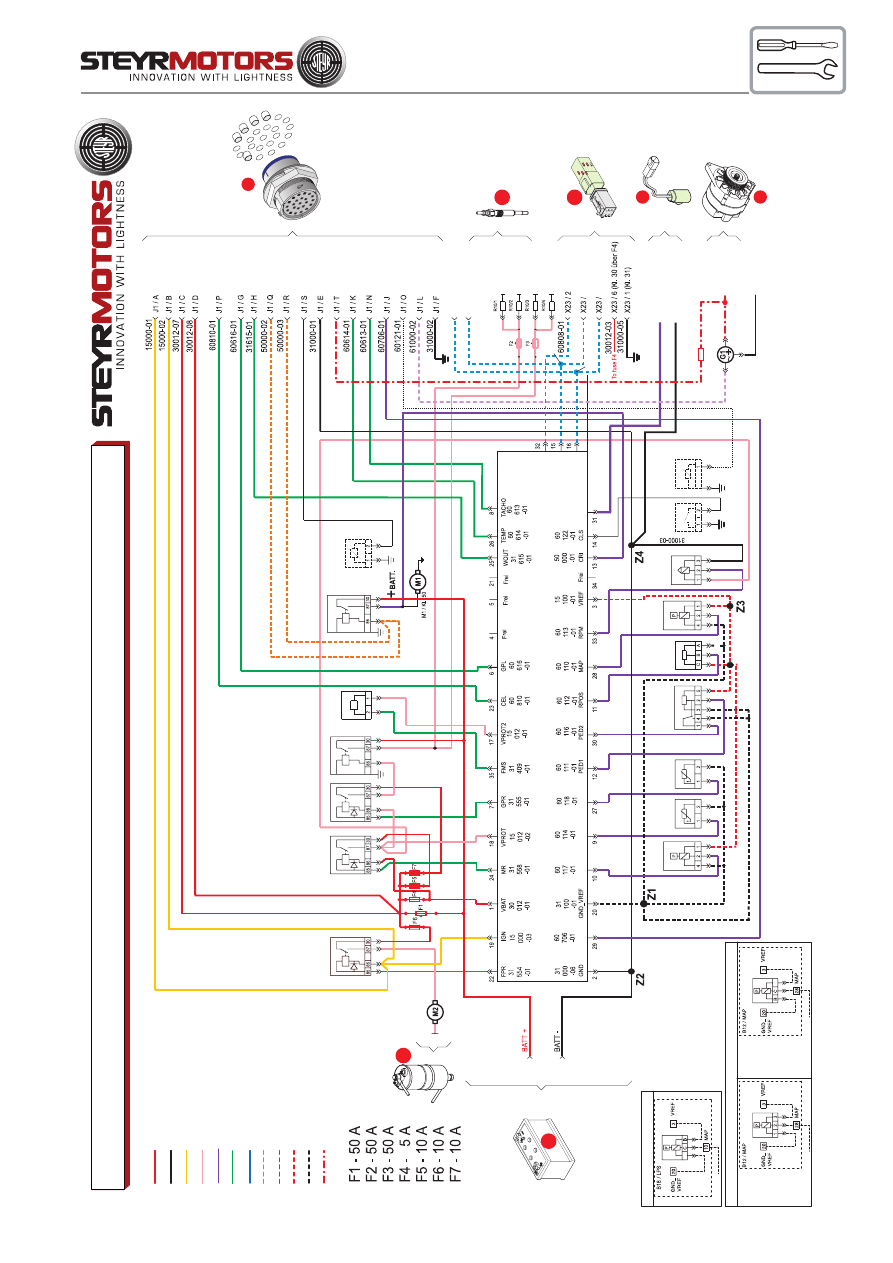
75
B16
Z5
Z6
A
B
C
D
E
F
G
H
J
K
L M N O
P
Q
R
S
T
V
W
X
U
R
Q
B
A
J1
STARTER
X23
1 2 3
6 5 4
1
2
3
6
5
4
S3
CONNECTOR "A5" (ELECTRONIC-CONTROL-UNIT)
J1 / U
J1 / V
60901-03
60900-03
60900-02
60901-02
5 CAN "H"
4 CAN "L"
X3/1 Invers
X3/2 Solas
60123-01
31000-1
1
61001-02
Batt + / 24V
D+ B+
B-
Batt - / 24 V
61001-01
F8
F8 - 5
A
2179345/0-02-070118_tedoc
WIRING DIAGRAM / MARINE - 6 CYLINDER - 24V (OPTION)
www
.steyr-motors.com
Batt +
Batt -
Ign 15
Supplied by Relais
Sens ECU
Control ECU
DIAG
Start
Charge D+
Sens 5V
Sens -
B+ 24V
G2
M2
Fuel Pump
Fuel Pump
Relay
K24
Main Relay
K27
Preheating Control Relay
K26/1
Preheating Load Relay
K26/2
Control Solenoid
Y20
Start Relay
K28
Trim-Sensor
(Option)
B22
60120-01
R10
60120-01
60808-01 ISO
60900-01 CAN-H
60901-01 CAN-L
60 123 -01 WS
G1
Sensor Oil Pressure
Gauge (Option)
B19
Gear Switch
S2
RPM
B15
Map
B12
RPOS
B14
PED
B13
EXT
B17
EXT
LPS
ECT
AUX
ECT
B18
LPS
Wiring LPS /
All engines before 2007
A
31100-10
15100-07
601
17-01
EXCEPTIONS: ONL
Y FOR
TYP:
MO
164M40
MO
174V40
MO
246K41
MO
256H45
MO
256K43
MO
266K43
A
31100-08
15100-05
601
10-01
Wiring MAP
/
All engines before 2007
31100-08
15100-05
601
10
-01
ALL
ENGINE
TYPES WITH FOLLOWING EXCEPTIONS
75
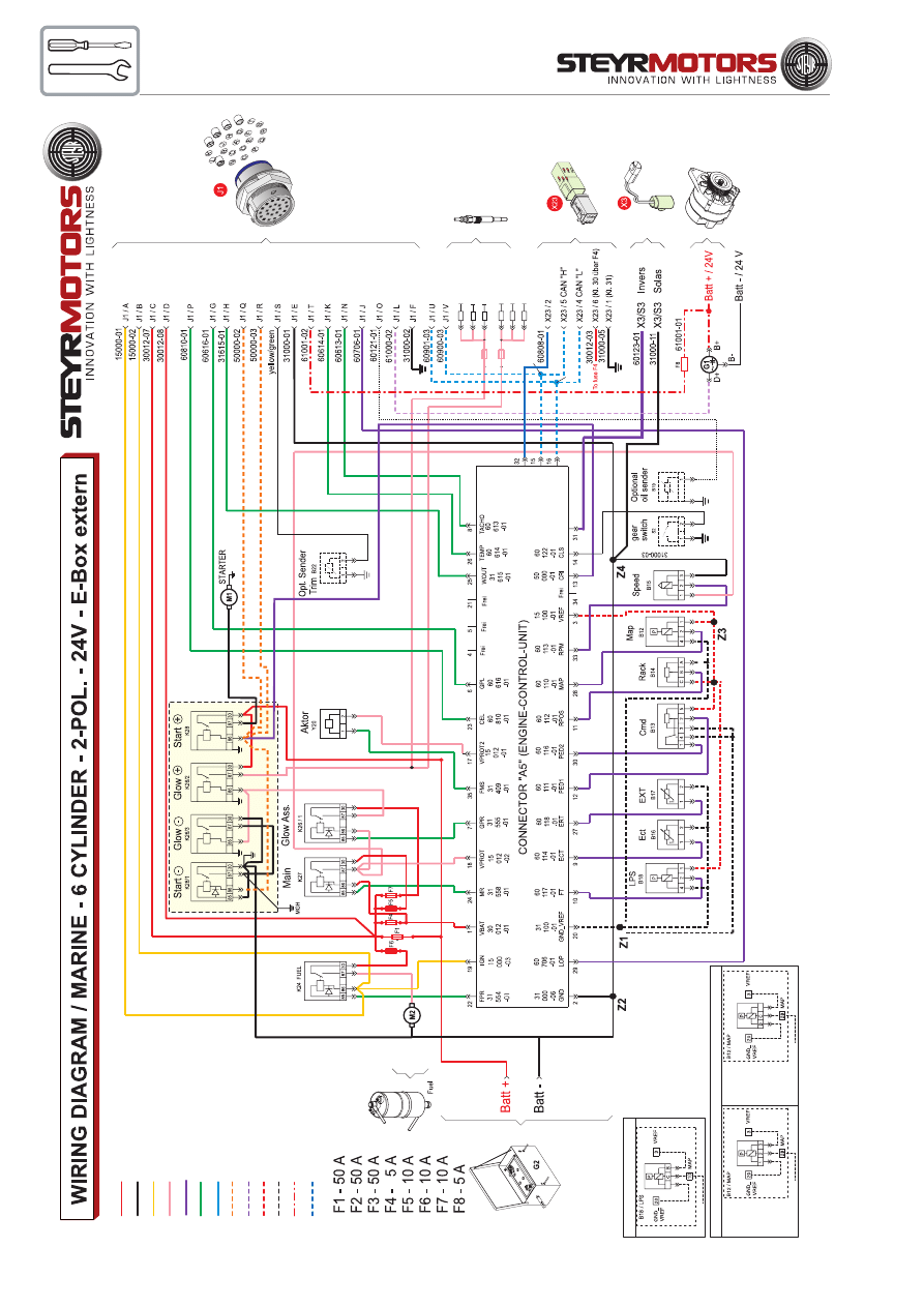
76
Z5
Z6
60900-02
60901-02
60808-01 ISO
60900-01 CAN-H
60901-01 CAN-L
60 123 -01 WS
2179351/0-02-070118_tedoc
www
.steyr-motors.com
R10/5
R10/1
R10/2
R10/3
R10/4
R10/6
Batt +
Batt -
Ign 15
Supplied by Relais
Sens ECU
Control ECU
DIAG
Start
Charge D+
Sens 5V
Sens -
B+ 24V
CAN
Wiring LPS /
All engines before 2007
A
31100-10
15100-07
601
17-01
EXCEPTIONS: ONL
Y FOR
TYP:
MO
164M40
MO
174V40
MO
246K41
MO
256H45
MO
256K43
MO
266K43
A
31100-08
15100-05
601
10-01
Wiring MAP
/
All engines before 2007
31100-08
15100-05
601
10-01
ALL
ENGINE
TYPES WITH FOLLOWING EXCEPTIONS

77
78
Description - Wiring harness instrument panels 4/6 cyl. marine engines
(current version)
Designat.
Component
Description
F9
fuse 10 A
J1
23-pin plug
connection engine cable - instrument cable
S1
switch
ignition (red)
S2
switch
start (green)
S3
switch
emergency cut off (orange)
S7
switch
key switch constant revolution (optional)
L1
lamp
charge control
L2
lamp
cel - check engine lamp
L3
lamp
oil pressure / preheating conrol
P1
gauge
engine coolant temperature
P2
gauge
oil pressure (optional)
P3
gauge
tachometer with running-time meter
H22
warning horn
E10
lighting
engine coolant temperature gauge
E11
lighting
oil pressure gauge (optional)
E12
lighting
tachometer gauge
X8
1-pin plug
connector illumination switch
X24
8-pin plug
connector STEYR - display
Z1
splice
battery +
Z2
splice
battery -
Z3
splice
ignition (+)
Z4
splice
key switch constant revolution
24 V
interm. cable
charge indicator
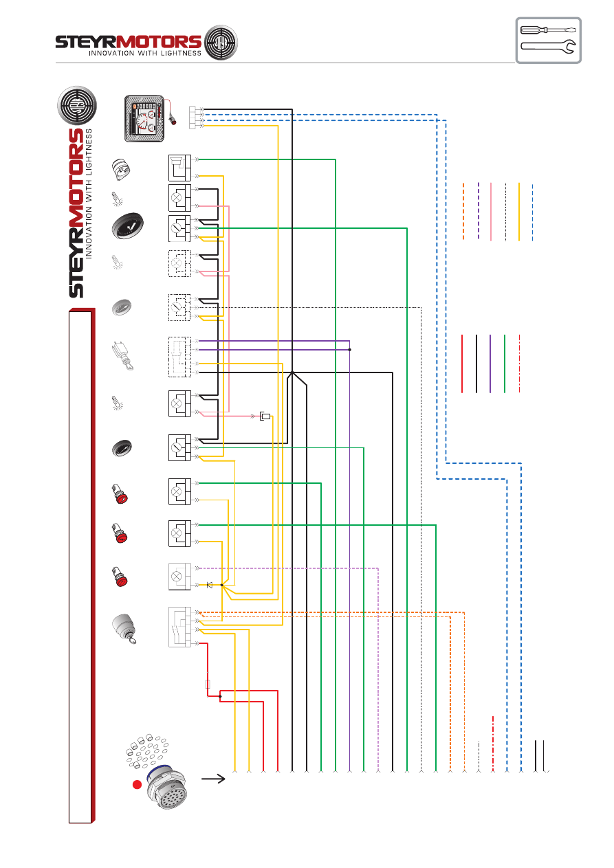
79
Connector Illumination
switch
Fuse 10A
X8
Z2
Z3
Z4
Z1
F9
A
B
C
D
E
F
G
H
J
K
L M N O
P
Q
R
S
T
V
W
X
U
R
Q
B
A
J1
SCC
X 24
1 2 3 4
58000-01
2179338/D-02-070627_tedoc
WIRING DIAGRAM / INSTRUMENT P
ANEL
- 4/6 CYLINDER - 12 V
Batt +
Batt -
Sens ECU
Control ECU
61 +24V
Start
Charge
Illumination
Option
15
60 CAN
www
.steyr-motors.com
Trim (Option)
(no connection)
(no connection)
No./colours of shielded wire correspond to
individual cable No. (15000-01)
J1 / A
1
J1 / B
2
J1 / C
3
J1 / D
4
J1 / E
5
J1 / F
6
J1 / G
7
J1 / H
8
J1 / J
9
J1 / K
10
J1 / L
11
J1 / M
J1 / N
13
J1 / O
14
J1 / P
15
J1 / Q
16
J1 / R
17
J1 / S
18
J1 / T
12
J1 / U
21
J1 / V
22
J1 / W
19
J1 / X
20
15000-01
15000-02
30012-07
30012-08
31000-01
3100-02
60616-01
31615-01
60706-01
60614-01
61000-02
31000-16 Ground shield
60613-01
60121-01
60810-01
50000-02
50000-03
60120-01
61001-01
B+ / 24V
60901-03
60900-03
- Start
Warning
Horn H22
+
_
Charge Control Lamp
L1
12
Check Engine Lamp
L2
12
OIL-
Preheating
control Lamp
L3
12
Engine Coolant
Temperature
Gauge
P1
40
10
5
17
5
21
0
25
0
°F
°C
40
80
12
0
10
0
+G
_
Lighting
ECT- Gauge E10
12
Opt. Gauge
Oil-
Pressure
P2
+G
_
Lighting
Opt. Gauge Oil-Pressure
E11
12
Opt. Key
Switch-Constant
Revolution
S7
14
22
13
21
Lighting RPM- Gauge
E12
15
RPM- Gauge
P3
0
10
40
20
30
23
4
Ignition Switch
S1
15
6
7
STEYR-CONTROL-CENTERSTEYR-CONTROL-CENTER
rpm
x
100
0
0
1
2
3
4
5
10.0
S
PEED
/K
N
2650
R
P
M
49
.16
.4
5N
102
.4
1.
11
W
57,
4
22
:57
MAIN
S
WI
TC
H
1
2
3
4
5
6
1
2
3
4
5
6
O
IL
/BAR
6.
3
TEMP
/°
C
77.
8
rpm x
1000
0
1
23
4
5
34
SPEED/KN
1500
RPM
48.08.56N
014.27.47W
11
7
14:05
0
2
4
6
8
50
85
120
2,8
73
OIL
TEMP
bar
°C
79
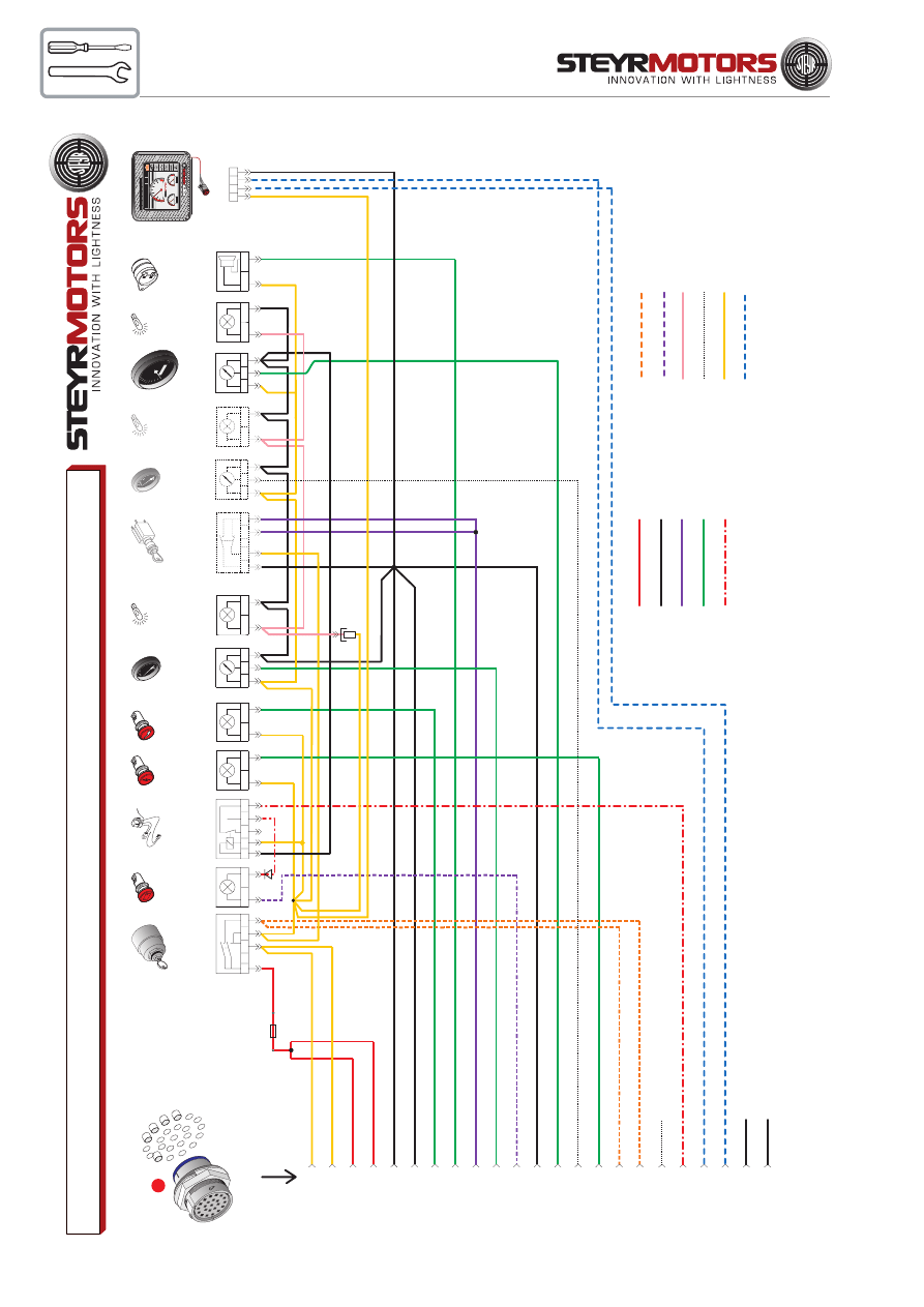
80
2179339/D-02-070627_tedoc
A
B
C
D
E
F
G
H
J
K
L M N O
P
Q
R
S
T
V
W
X
U
R
Q
B
A
J1
58000-01
WIRING DIAGRAM / INSTRUMENT P
ANEL
- 4/6 CYLINDER - 24V (OPTION)
Batt +
Batt -
Sens ECU
Control ECU
61 +24V
Start
Charge
Illumination
Option
15
60 CAN
www
.steyr-motors.com
Trim (Option)
(no connection)
(no connection)
No./colours of shielded wire correspond to
individual cable No. (15000-01)
J1 / A
1
J1 / B
2
J1 / C
3
J1 / D
4
J1 / E
5
J1 / F
6
J1 / G
7
J1 / H
8
J1 / J
9
J1 / K
10
J1 / L
11
J1 / M
J1 / N
13
J1 / O
14
J1 / P
15
J1 / Q
16
J1 / R
17
J1 / S
18
J1 / T
12
J1 / U
21
J1 / V
22
J1 / W
19
J1 / X
20
15000-01
15000-02
30012-07
30012-08
31000-01
3100-02
60616-01
31615-01
60706-01
60614-01
61000-02
31000-16 Ground shield
60613-01
60121-01
60810-01
50000-02
50000-03
60120-01
61001-01
B+ / 24V
60901-03
60900-03
Connector Illumination
switch
Fuse 10A
X8
Z2
Z3
Z4
Z1
F9
Intermediate Cable Charge
Indicator
24 V
85
86
87a
87
30
- Start
Warning
Horn H22
+
_
Charge Control Lamp
L1
12
Check Engine Lamp
L2
12
OIL-
Preheating
control Lamp
L3
12
Engine Coolant
Temperature
Gauge
P1
40
10
5
17
5
21
0
25
0
°F
°C
40
80
12
0
10
0
+G
_
Lighting
ECT- Gauge E10
12
Opt. Gauge
Oil-
Pressure
P2
+G
_
Lighting
Opt. Gauge Oil-Pressure
E11
12
Opt. Key
Switch-Constant
Revolution
S7
14
22
13
21
Lighting RPM- Gauge
E12
15
RPM- Gauge
P3
0
10
40
20
30
23
4
Ignition Switch
S1
15
6
7
SCC
X 24
1 2 3 4
STEYR-CONTROL-CENTERSTEYR-CONTROL-CENTER
rp
m
x
1000
0
1
2
3
4
5
10
.0
S
PEED
/KN
2650
RPM
49
.1
6.4
5N
10
2.41.1
1W
57,
4
22:
57
M
AIN
SWITCH
1
2
3
4
5
6
1
2
3
4
5
6
OIL/BA
R
6.
3
TEMP
/°
C
77.
8
rpm x
1000
0
1
23
4
5
34
SPEED/KN
1500
RPM
48.08.56N
014.27.47W
11
7
14:05
0
2
4
6
8
50
85
120
2,8
73
OIL
TEMP
bar
°C
80

81
A
B
C
D
E
F
G
H
J
K
L M N O
P
Q
R
S
T
V
W
X
U
R
Q
B
A
J1
Trim (Option)
Optional
24
V
ohne Anschlag (no connection)
ohne Anschlag (no connection)
58000-01
2179340/D-02-070627_tedoc
WIRING DIAGRAM / INSTR. P
ANEL
- 4/6 CYL. - Solas - 12V
(OPTION)
www
.steyr-motors.com
Batt +
Batt -
Sens ECU
Control ECU
61 +24V
Start
Charge
Illumination
Option
15
60 CAN
- Start
No./colours of shielded wire correspond to
individual cable No. (15000-01)
J1 / A
1
J1 / B
2
J1 / C
3
J1 / D
4
J1 / E
5
J1 / F
6
J1 / G
7
J1 / H
8
J1 / J
9
J1 / K
10
J1 / L
11
J1 / M
J1 / N
13
J1 / O
14
J1 / P
15
J1 / Q
16
J1 / R
17
J1 / S
18
J1 / T
12
J1 / U
21
J1 / V
22
J1 / W
19
J1 / X
20
15000-01
15000-02
30012-07
30012-08
31000-01
3100-02
60616-01
31615-01
60706-01
60614-01
61000-02
31000-16 Ground shield
60613-01
60121-01
60810-01
50000-02
50000-03
60120-01
61001-01
B+ / 24V
60901-03
60900-03
Connector Illumination
switch
Fuse 10A
X8
Z2
Z3
Z4
F9
Z1
34
START (green)
S2
34
IGN (red) ON/OFF
S1
MM
Emergency CUT OFF
Switch
S3
Warning
Horn H22
+
_
Charge Control Lamp
L1
12
Check Engine Lamp
L2
12
OIL-
Preheating
control Lamp
L3
12
Engine Coolant
Temperature
Gauge
P1
40
10
5
17
5
21
0
25
0
°F
°C
40
80
12
0
10
0
+G
_
Lighting
ECT- Gauge E10
12
Opt. Gauge
Oil-
Pressure
P2
+G
_
Lighting
Opt. Gauge Oil-Pressure
E11
12
Opt. Key
Switch-Constant
Revolution
S7
14
22
13
21
Lighting RPM- Gauge
E12
15
RPM- Gauge
P3
0
10
40
20
30
23
4
SCC
X 24
1 2 3 4
STEYR-CONTROL-CENTERSTEYR-CONTROL-CENTER
rpm
x
1000
0
1
2
3
4
5
10.
0
S
PEED
/K
N
265
0
RPM
49
.16
.45N
102
.4
1.
11
W
57
,4
22
:57
MAIN
S
WIT
CH
1
2
3
4
5
6
1
2
3
4
5
6
O
IL
/BAR
6.
3
TEMP
/°
C
77.
8
rpm x
1000
0
1
23
4
5
34
SPEED/KN
1500
RPM
48.08.56N
014.27.47W
11
7
14:05
0
2
4
6
8
50
85
120
2,8
73
OIL
TEMP
bar
°C
81
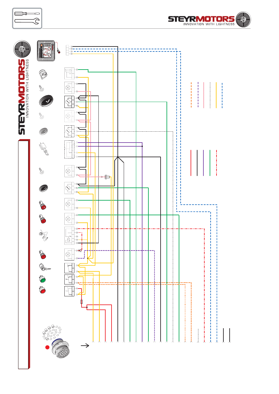
82
34
34
MM
A
B
C
D
E
F
G
H
J
K
L M N O
P
Q
R
S
T
V
W
X
U
R
Q
B
A
J1
58000-01
Trim (Option)
(no connection)
(no connection)
2179341/D-03-070627-tedoc
WIRING DIAGRAM / INSTR. P
ANEL
- 4/6 CYL. - Solas - 24V (OPTION)
Batt +
Batt -
Sens ECU
Control ECU
61 +24V
Start
Charge
Illumination
Option
15
60 CAN
IGN (red) ON/OFF
S1
START (green)
S2
Emergency CUT OFF
Switch
S3
Charge Control Lamp
L1
Intermediate Cable Charge
Indicator
24 V
Check Engine Lamp
L2
OIL-
Preheating
control Lamp
L3
Engine Coolant
Temperature
Gauge
P1
Lighting
ECT- Gauge E10
Opt. Key
Switch-Constant
Revolution
S7
Opt. Gauge
Oil-
Pressure
P2
Lighting
Opt. Gauge Oil-Pressure
E11
RPM- Gauge
P3
Lighting RPM- Gauge
E12
Warning
Horn H22
www
.steyr-motors.com
0
10
40
20
30
40
10
5
17
5
21
0
25
0
°F
°C
40
80
12
0
10
0
No./colours of shielded wire correspond to
individual cable No. (15000-01)
Connector Illumination
switch
+
_
J1 / A
1
J1 / B
2
J1 / C
3
J1 / D
4
J1 / E
5
J1 / F
6
J1 / G
7
J1 / H
8
J1 / J
9
J1 / K
10
J1 / L
11
J1 / M
J1 / N
13
J1 / O
14
J1 / P
15
J1 / Q
16
J1 / R
17
J1 / S
18
J1 / T
12
J1 / U
21
J1 / V
22
J1 / W
19
J1 / X
20
15000-01
15000-02
30012-07
30012-08
31000-01
3100-02
60616-01
31615-01
60706-01
60614-01
61000-02
31000-16 Ground shield
60613-01
60121-01
60810-01
50000-02
50000-03
60120-01
61001-01
B+ / 24V
60901-03
60900-03
Fuse 10A
1
2
85
86
87a
87
30
1
2
1
2
+
G
_
1
2
14
22
+
G
_
12
13
21
1
5
23
4
- Start
X8
Z2
Z3Z3
Z4
Z1
F9
SCC
X 24
1 2 3 4
STEYR-CONTROL-CENTERSTEYR-CONTROL-CENTER
rpm
x
100
0
0
1
2
3
4
5
10
.0
S
PEED
/K
N
2650
R
P
M
49
.16
.4
5N
102
.4
1.
11
W
57,4
22
:57
MAIN
S
WI
TCH
1
2
3
4
5
6
1
2
3
4
5
6
O
IL
/BAR
6.
3
TEMP
/°
C
77.
8
rpm x
1000
0
1
23
4
5
34
SPEED/KN
1500
RPM
48.08.56N
014.27.47W
11
7
14:05
0
2
4
6
8
50
85
120
2,8
73
OIL
TEMP
bar
°C

83
DEALER´S ACTIVITIES
Check motor oil level ............................................................................... 85
Refill motor oil ........................................................................................... 85
Oil level power steering ............................................................................ 85
Oil level transmission ............................................................................... 85
Check coolant .......................................................................................... 86
Drain raw water circuit of the engine ........................................................ 86
Check raw water ....................................................................................... 86
Cooling system anodes ............................................................................ 87
Air filter ..................................................................................................... 88
Maintenance Poly-V-belt .......................................................................... 88
Engine alignment ...................................................................................... 88
Adjustment of belts ................................................................................... 89
Propeller selection .................................................................................... 91
STEYR Dealer - Check - List .................................................................... 92
Installation and pre - delivery inspection log ............................................. 94
Preparation for off-season storage ........................................................... 95
Start-up after storage ............................................................................... 95
Engine log (logbook) ................................................................................ 96

84
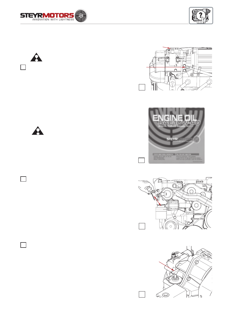
85
Check motor oil level
ATTENTION:
Check with cooled down engine only, or
after a shut down periode of app. 3 to 5 min.
Then remove oil dipstick (19/A), clean it and insert again into
oil dipstick tube (19/A), then remove again and check oil level
on marker.
Refill motor oil
Remove motor oil filler cap (19/B) and add STEYR TURBO DIESEL
ENGINE OIL 5 W-50 / 10 W-40 or an equivalent marked ACEA
B4 - 02 / E7 or with API Code CF up to specified maximum marker
on oil dipstick.
ATTENTION: Motor oil must not exceed maximum marker. An
overfilling results in high operating temperatures,
foaming (air in oil), loss in efficiency and reduced
engine life.
Put on the motor oil filler cap.
NOTE:
Remove possible oil contaminations.
The use motor oil with other quality than specified
warranty can expire.
Oil level for Power Steering
Whenever you check motor oil level, also check oil level of
powersteering. If required, add automatic transmission oil
(available with your STEYR Marine dealer). Other approved
oils, such as GM Servo or Dexron II, may also be used. Do not
overfill pump reservoir.
Oil level for Transmission
Whenever you check motor oil level, also check oil level of
transmission. If required, add automatic transmission oil
(available with your STEYR Marine dealer). Other approved
oils, such as GM Servo or Dexron II, may also be used. Do not
overfill transmission.
Note: Consider specifications of respective transmission
manufacturer.
21
20
19
22
06005
19
A
B
06006
21
22
06007
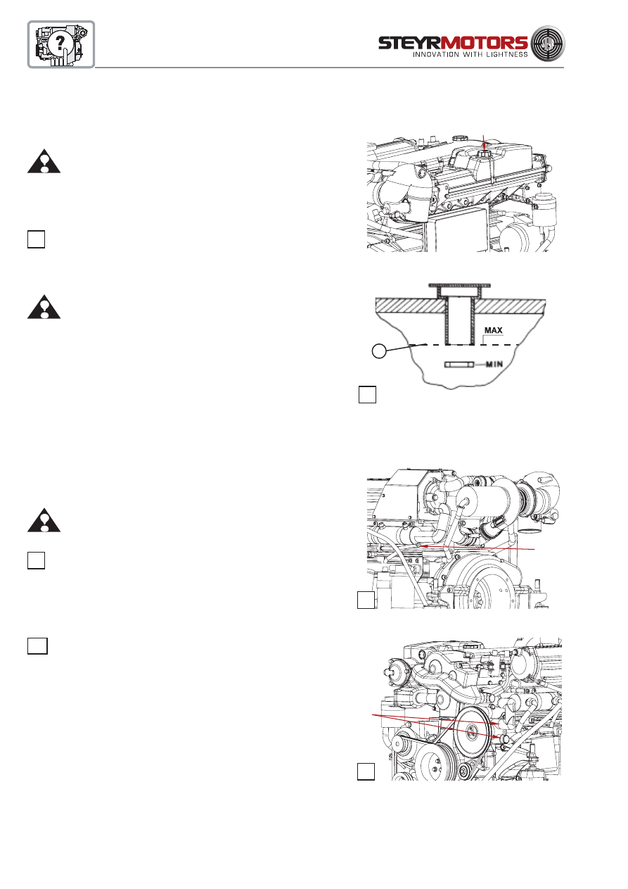
86
Check coolant
(closed cooling circuit)
ATTENTION:
With hot engine, the closed cooling circuit is
under pressure. Do not try to open the radiator
cap or the drain plugs when engine is hot. This
may cause severe injuries by hot coolant. As soon
as the engine has cooled down, the cap may be
opened.
Remove radiator cap (23/A). Coolant level should reach the
"MAX" marking (23/B) in the expansion tank.
ATTENTION:
Only add STEYR MOTORS engine coolant.
NOTE:
When not using the original STEYR coolant, severe
damage to the cooling system of your engine
may occur.
Drain the raw water circuit of the engine
ATTENTION:
Not draining the raw water circuit in time before
the winter season and/or daily when running the
engine during the winter season, may lead to
freeze demage on the engine.
Remove drain plug (24/A). Engine empties itself via exhaust
system.
NOTE:
Drain plug (24/A) is not availabe for all types.
Loosen 2 hose clamps (25/A) and remove raw water hoses,
quickly start the engine so that raw water pump empties itself.
NOTE:
As to procedure for draining the remaining
equipment on your boat, see your STEYR Marine
dealer.
Check raw water
(open circuit with pump)
Filling is done automatically via raw water pump after having
started the engine.
23
23
24
25
B
A
06020
24
06015
A
25
06016
A
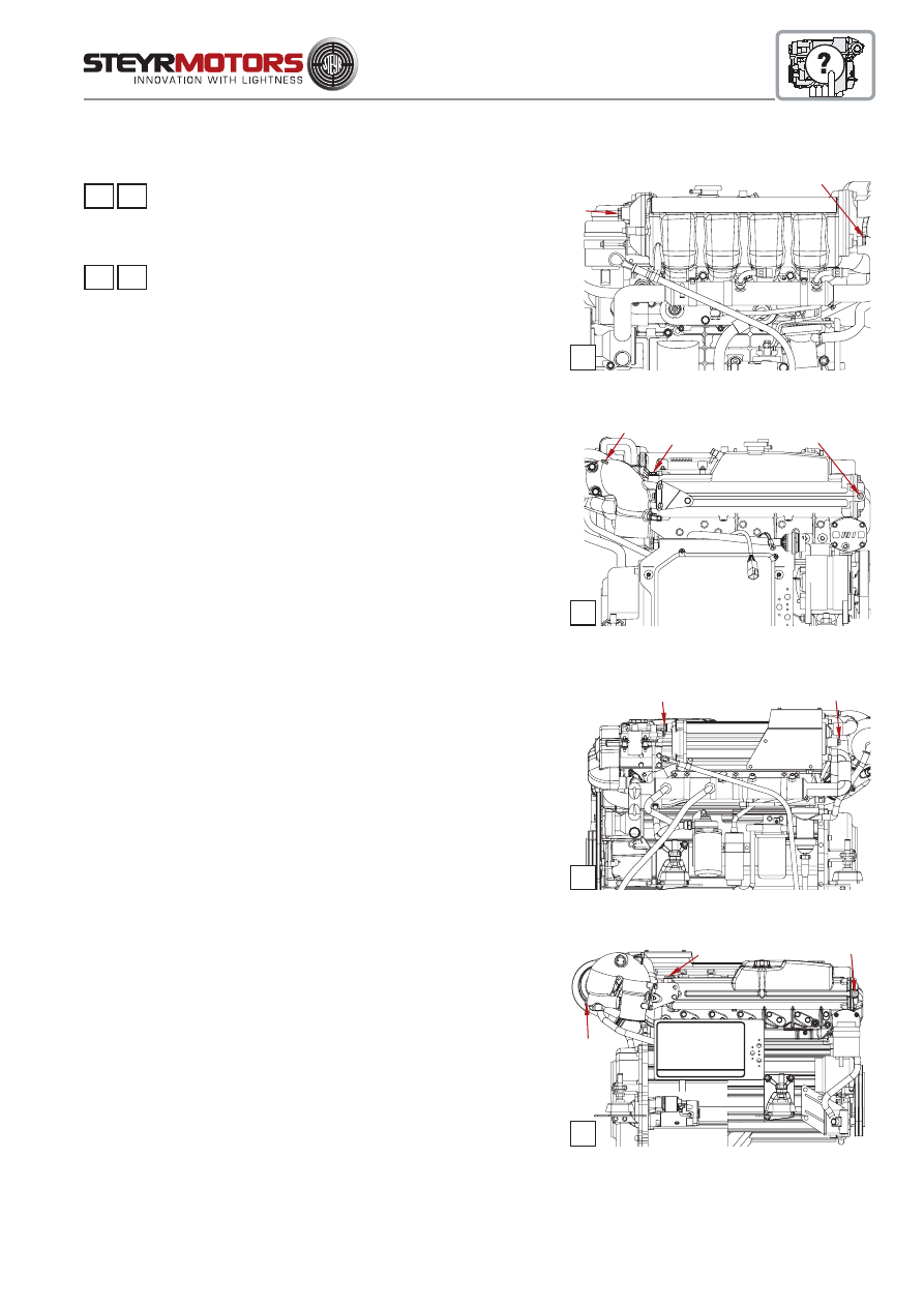
87
Cooling System Anodes
There are a total of 5 sacrificial zink anodes in the raw water cooling
system. Which are installed as per ill. 26 and 27.
Remove and inspect anodes for galvanic erosion according to the
maintenance schedule.
Replace anode when material loss is 50-75 %.
Anti-Corrosion Anodes
If additional electronic equipment is installed, each should have an
individual anode or grounding device and all grounding devices must
be interconnected. Follow recommandations of manufacturers of
equipment.
NOTE:
Inspect anodes every 30 days, or more frequently if
used in extremely salty water. Anode is to be replaced
according to the maintenance schedule.
Boats that connect to an AC power source (shore power) require
protection against increased potential of galvanic and “spray current”
corrosion. For protection, a galvanic isolator can be installed in series
with the grounding (green) wire in the shore power cable between the
boat and the shore power outlet on the dock. The isolator blocks direct
current (DC) flow, but permits the passage of alternating current (AC)
thus providing a path for ground fault currents.
NOTE:
If a boat is connected to an AC power source (shore
power), and it is not equipped with a galvanic isolator, the
zinc anti-corrosion anodes may be unable to handle the
added corrosion potential.
26 27
FOR ALL 4 CYL. MARINE ENGINES
28 29
FOR ALL 6 CYL. MARINE ENGINES
GENERAL
26
06017
1
2
27
06018
4
3
5
1
28
06021
2
3
29
06022
4
5
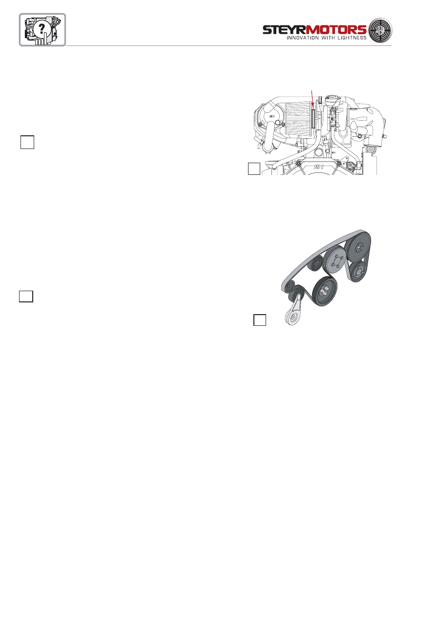
88
Maintainance Poly - V - belt
Occassionally check components for excessive wear
and/or clearance on tension bearing.
NOTE*):
It is recommended to spray frequently some corrosion inhibiting spray into the spring housing of the belt
tensioner.
Engine alignment
Engine alignment requires special tools. The output coupler must be
disengaged from the take-off shaft. This should be rechecked during
off-season storage preparations. Because of the special tools required,
engine alignment is to be performed by a STEYR Marine dealer.
NOTE:
Failure to check the engine alignment could result in premature failure of engine coupler or universal joints.
32
Air Filter
All STEYR Marine Engine models are equipped with an air filter at
the turbocharger inlet; as to specifications, see Specifications and
Maintenance.
Loosen clamp to exchange air filter. Remove air filter. Place
clamp on filter neck and mount air filter onto flange. Tighten
clamp. (3 Nm)
31
32
*)
GENERAL
FOR ALL 4 CYL. MARINE ENGINES
31
06023
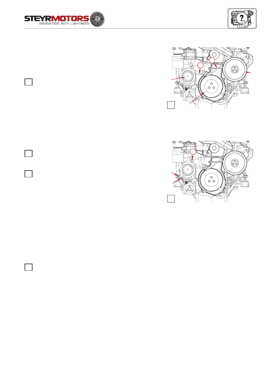
89
Adjustment of belts
Measuring device VR00515/0 for toothed- and V-belt
With engine stopped, tension of the belt should be so that it
yields for 6-13 mm (350 ± 50 N) when pressing your finger on marked
spots (A) and (B) . If the belt is too slack, it may slip through which
results in higher wear and bad efficiency of generator or pump. Belt
tension is to be checked after first 10 operating hours and then every
50 operating hours.
NOTE:
Alternator belts and servo pump belts are special
Marine belts. DO NOT replace by traditional
V-belts.
Alternator belt
Check tension of alternator belt on spot (A) in the center
between crankshaft belt pulley (1) and alternator belt pulley (2).
Retighten the belt: - Loosen the alternator holding-down bolts
(34/C) and (34/D). Turn the clamping bolt (E) clockwise, (turn away
alternator from engine) and increase belt tension (350 +/- 50 N).
Tighten screws (C) and (D). Check belt tension.
Servopump belt (if so)
NOTE:
Servopump is jointly driven with alternator,
tension belt via alternator.
Belt for raw water pump
Check tension of belt for raw water pump halfway (B) between
crankshaft belt pulley (1) and belt pulley on raw water pump (3).
FOR ALL 6 CYL. MARINE ENGINES
33
33
34
33
33
06024
1
2
3
B
A
34
06025
E
D
C
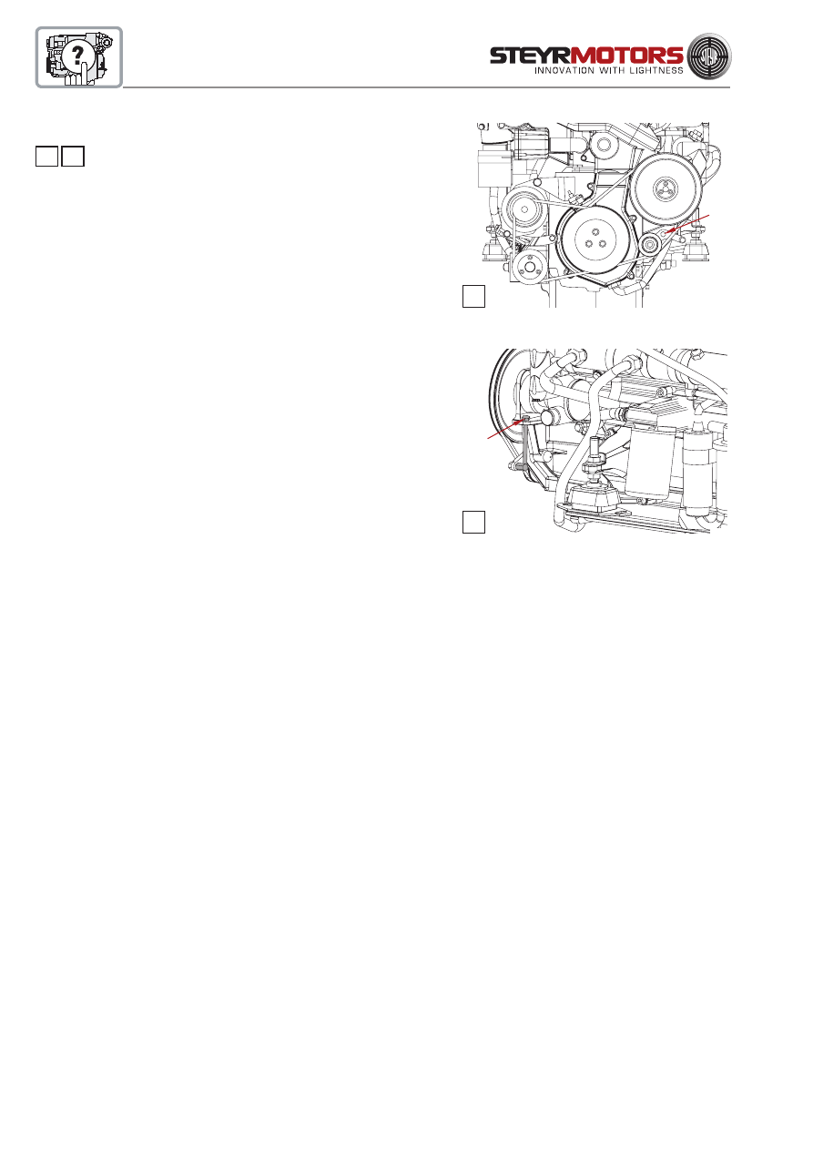
90
35 36
To tension the belt: - Loosen hexagon screw (35/F).Turn the
clamping bolt (36/G) clockwise in order to increase the belt tension to
300 +/- 50 Nm. Tighten hexagon screw (35/F) with a Torque of 23 Nm
+/-2 to secure idle pulley bracket. Check belt tension.
FOR ALL 6 CYL. MARINE ENGINES
35
06026
F
36
G
06027
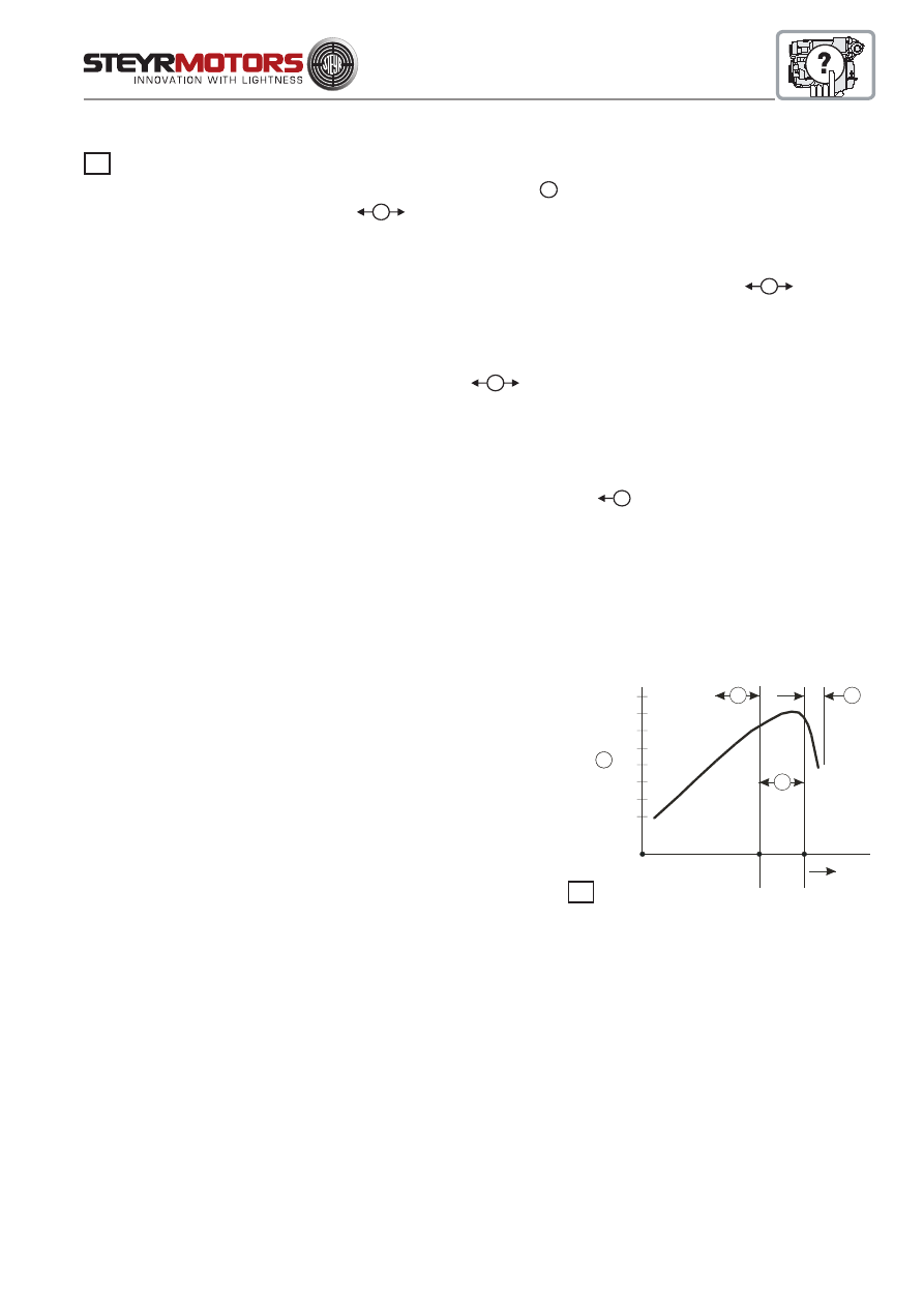
91
Propeller Selection
Your STEYR Marine dealer has chosen a propeller designed to deliver top performance and economy under most
conditions. To obtain the maximum percentage of available output (
A
), the engine RPM at Full Throttle should be in
the specified Full Load Speed Range (
B
). As to specifications, see Technical Data and Maintenance.
If the engine's full throttle RPM with normal load is below the specified range, use a propeller with less pitch to increase
the RPM. Should the engine's full throttle RPM exceed the specified range, the engine RPM and output is limited by
the governor. Use a propeller of higher pitch to achieve a RPM reduction in the specified range (
B
).
NOTE:
Engine damage can result from incorrect propeller selection if
• The engine RPM does not attain the specified "Full Load Speed Range".
The engine thus runs in RPM range (
C
).
Therefore, use a propeller with a lower pitch.
• The engine RPM exceeds the specified "Full Load Speed Range".
Engine speed is therefore above the admissible range (
D
).
Therefore, use a propeller with a higher pitch.
The full load speed range can be calculated as follows:
Lower limit = Rated speed - 300 RPM.
Upper limit = Rated speed - 100 RPM.
e.g. MO256H45 = 4500 - 300 = 4200 RPM MIN.
4500 - 100 = 4400 RPM MAX.
GENERAL
OUTPUT POWER
A
RPM
Full
Load
Speed
Range
30%
40%
50%
60%
70%
80%
90%
100%
B
C
D
37
37

92
STEYR - Dealer - Check- List
1. Remove carton from palette and check the separately packed components are complete and undamaged.
2. Visual inspection of engine for transit damage and finish.
3. Check coolant and oil level. If required add operational fluids as specified in Operation, Maintenance & War-
ranty Manual and Service Manual.
4. Inform customer about important guidelines in the Installation Manuals and instruct him as to safety regula-
tions.
5. Inform customer about break-in procedure in the Operation, Maintenance & Warranty Manual.
6. Advise customer what to do when the engine’s self-diagnostic management system reduces the power. See
Electronic Engine Control Unit (ECU) in section Start-up and Operation of Operation, Maintenance & Warranty
Manual.
7. Check tightness of all cooling water hose clamps.
8. Check fuel hoses for correct size and safe routing to and from engine.
9. Check battery units for correct polarity and battery for correct capacity.
10. Check all electrical connections (engine harness, main connector, accessories, instrument panel)
11. Check level of all operational fluids:
Motor oil
Coolant
Power steering fluid
Drive or gear
Reservoir of trim pump
12. Fill fuel tank for engine test run.
13. Check function of displays on instrument panel.
14. Check function of bilge pump and blower.
15. Check fuel system for free flow and leaks.
16. Check function of trim installation
17. Check function of anchor light, navigation lights and instrument panel lights.
18. Install drain plug of bilge

93
19. Steering – Lubricate cable ram with OHD-bearing grease p/No. Z010084/0
20. Check condition and tension of all drive belts.
21. Check all engine mount screws for tight seat.
22. Check for any leaks, deficiencies, signs of wrong use etc.
23. Check function of all warning devices installed.
24. Read out memorized service codes and make necessary corrective actions
25. Start engine and check for normal instrument display and normal operating noise.
26. Obtain propeller load absorption.
27. Check installation and fill in installation and pre-delivery inspection log. (See next page)
28. Grease raw water pump impeller at BUKH-STEYR SOLAS engine with original grease of P/N. Z011753/2.
29. Carry out Start-Idle-Test and check engine operation. Check behavior of the boat when engine is in idle gear. If
there are unpleasant vibrations, adjust the engine speed to a vibration-free operation (see Service Manual)
30. Check correct function of gearshift.
31. Stop engine and check again the levels of all operational fluids during test run a certain loss operation fluids
may occur.
........................................................................ ................................................................................
(Mechanic's Signature)
(Dealer's Signature)
DEALER:....................................................................................................................................................................
ADDRESS AND DATE: .............................................................................................................................................
ENGINE TYPE/SERIAL NUMBER: ...........................................................................................................................
ENGINE RUNNING HOURS: ....................................................................................................................................
SIGNATURE:..............................................................................................................................................................
A copy of the "installation and pre-delivery inspection log" is to be sent to
STEYR MOTORS GmbH, After Sales Service!

94
Installation and pre-delivery inspection log: engine no: ......................................
Boat Owner:
Company/Name: ................................................................................................................................
Address/Phone:............................................................................................................................. .....
Dealer:
Company:
..................................................................................................................................
Address/Phone:..................................................................................................................................
Dimension of propellers: ..............................
Transmission:
...................................
Gear reduction:
...................................
Engine type: ................................
Engine model:
...................................
Serial number:
...................................
Measuring data with rated power:
Max. boat speed: ...................................
Max. engine speed: .................................
Cross-sect. air intake duct eng.comp.:..........cm
2
Temperature engine compartment ..... ° C
Boost-pressure at max. rpm.: .......... mbar
Exhaust backpressure: .................... mbar
Motor oil pressure
.............................. bar
Engine coolant temperature: ................... ° C
Exhaust gas / raw water temperature: ..... ° C
Fuel rate of flow at idle run
(measured from return line): ................. l/min
Idle speed:
............................ rpm.
Name of datalog:............................................
Model No.:
...................................
Boat length:
................................ m
Boat weight:
............................... kg
Driving system:
...................................
Propeller:
...................................
Level of operating fluids (motor oil, gear oil, hydraulic oil, cooling agent) checked yes
Leakage (oil, fuel, coolant) checked: ..................................................................................................
Instruments adjusted: .........................................................................................................................
Type of secondary drive (if available): ................................................................................................
Type of cabin heating (if available): ....................................................................................................
2nd control station (if available): .........................................................................................................
CEL - extinguishes after 0,7 sec: YES NO
Test made on:............................, by.................................................................. (Name in block letters)
Please immediately return a copy of this report and the Warranty registration card to your
STEYR MOTORS GENERAL DISTRIBUTOR. If not doing so, guarantee will expire!!
Safeguarding instruction carried out yes
Manual, warranty and operation explained yes
Type of boat:
..................................................................................................................................
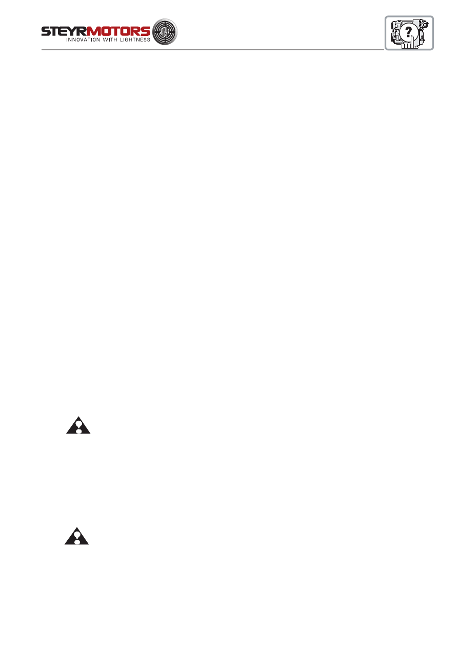
95
Start-up after Storage
An adequate start-up of the engine will contribute to an efficient and troublefree operation in the long term.
Your STEYR Marine Dealer will gladly be available as consultant or for an expert performance.
1.Check condition of hoses and hose clamps.
2.Clean battery terminals.
ATTENTION:
Connect RED cable to positive terminal and then BLACK cable to negative terminal.
Wrong connection of battery terminals may damage the electronic system.
3.Grease outer sides of terminals.
4.Open fuel stop valve and check all fuel lines for leakage.
5.Thoroughly check the boat and engine for slack or missing screws or nuts.
6.Pump the bilge dry and clean the engine compartment.
7.Complete the raw water system.
8.Open the raw water inlet.
ATTENTION: Insufficient raw water supply may damage the engine and the raw water pump.
9.Test run. Start engine. Check voltmeter, oil pressure- and water temperature gauge. (Make sure that all systems
function properly.)
10.Check all parts for oil-, fuel- or water leakage.
Preparations for Off-Season Storage
An adequate preserving of the engine will contribute to an efficient and troublefree operation in the long term.
Consult your STEYR Marine Dealer to get professional assistance in performing a proper off season storage.
1.Change motor oil and oil filter.
2.Change fuel filter.
3.Check air filter.
4.Check coolant (closed circuit).
5.Add fuel stabilizer to fuel.
6.Drain engine's raw water system.
NOTE:
If the raw water is not completely removed from the engine, expensive freeze damage may be
the result.
7.Drain raw water system from boat and driving system (consider manufacturer's instructions as to storage).
8.Change gear oil or lubricant.
9.Disconnect battery and store it.
10.Spray engine outside with corrosion preventing oil.
11.Ventilate engine compartment and bilge.
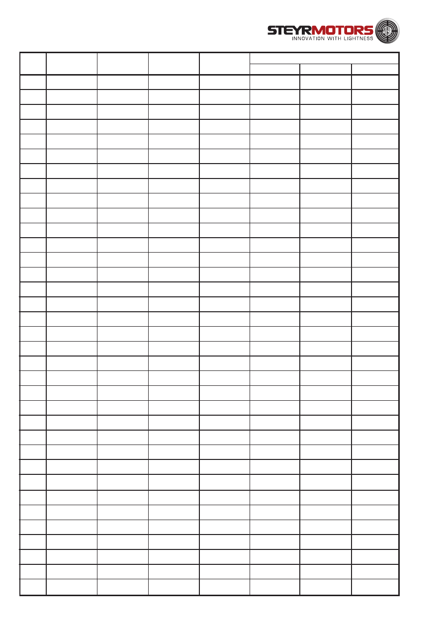
96
Number
Abord
Engine
Started
Destination
Date
Engine
Stopped
Inspection
Tune-up
Lubrication
Service Record
ENGINE LOG
97
Number
Abord
Engine
Started
Destination
Date
Engine
Stopped
Inspection
Tune-up
Lubrication
Service Record
ENGINE LOG
98
Number
Abord
Engine
Started
Destination
Date
Engine
Stopped
Inspection
Tune-up
Lubrication
Service Record
ENGINE LOG

99
WARRANTY
Marine Warranty Conditions ................................................................... 100
Engine, Gearbox, Boat model and Hull Identification Numbers .............. 105
Owner Identification Card ....................................................................... 106
Appendix 1 ............................................................................................. 107
Service Network ..................................................................................... 108

100
ENGINE WARRANTY CONDITIONS
STEYR MOTORS Limited Warranty
STEYR MOTORS GmbH, herein after „STEYR MOTORS“, warrants to the original retail purchaser that it will
make any repairs or replacements necessary to correct defects in material and / or workmanship of STEYR
MOTORS products for the Base Engine Warranty period. If no extra local legal conditions apply then the general
EU implied Warranty conditions are valid. The final customer is responsible that the required papers are
completed and returned to STEYR MOTORS as stated below.
The customer hereby declares that all given information may be recorded and for future usage at STEYR
MOTORS discretion.
International Owner Registration
The STEYR MOTORS Distributor, who is responsible for administering the Warranty registration/claim program
for your area, must forward the Warranty Registration Card to STEYR MOTORS Austria.
The Product Warranty is not fully effective unless the product is registered at the factory within a maximum period
of 60 days from the date of hand over to the final customer. Failure to Warranty the product within the above
period will cause the start date of Warranty to be fixed to the shipment date from STEYR MOTORS.
The Warranty Registration Card identifies the customers name and address, product model and serial numbers,
date of sale, type of use and the selling Distributor’s/Dealer’s code number, name and address. The Distributor/
Dealer also certifies that you are the original purchaser and user of the product.
A copy of the Warranty Registration Card, designated as the „Purchasers Copy“, MUST be given to you
immediately after the card has been completely filled out by the selling Distributor/Dealer. This card presents your
factory registration identification, and should be retained by you for future use when required. Should you ever
require warranty service on this product, your Dealer may ask you for the Warranty Registration Card to verify
date of purchase and to use the information on the card to prepare the Warranty claim form(s).
Base Engine Warranty
This Warranty covers any failures of the Product under normal use and service which result from a defect in
STEYR MOTORS material or factory workmanship. The Duration commences on either the date of delivery of
the Product, or the date the unit is first leased, rented or loaned, or when the Product has been operated for 25
hours / 500 km, whichever occurs first.
STEYR MOTORS Responsibilities
During the Base Engine Warranty
STEYR MOTORS will pay for all parts and labour needed to repair the damage to the Product resulting from
Warrantable Failure when performed during normal business hours. All labour costs will be paid in accordance
with STEYR MOTORS published standard repair time guidelines.
STEYR MOTORS will pay for the lubricating oil, antifreeze, filter elements, and other maintenance items that are
not reusable due to the Warrantable Failure.
STEYR MOTORS will pay for reasonable labour costs for Engine removal and reinstallation when it is necessary
to repair a Warrantable Failure.
STEYR MOTORS reserves the right to improve or modify products without assuming any obligation to modify
previously manufactured Products.

101
International Owner Registration (Continued)
Registration lists must be maintained by the factory and Dealer in some countries by law. It is your
desire to have ALL products registered at the factory should it even be necessary to contact you. Make
sure your Dealer/Distributor fills out the Warranty registration card and sends the factory copy to the
STEYR MOTORS Distributor for your area.
When you purchase the STEYR engine as well as the Stern Drive ( Bravo series) made by
Mercruiser
The Stern Drive Warranty for MerCruiser BRAVO series is covered according MerCruiser International
Warranty policy. Please fill in the „Warranty Registration Card“ that comes with the Stern Drive, and
send the card to the connected Mercruiser channel.
Pleasure Duty
This power rating is for use in variable load applications where full power is limited to one (1) hour out of
every eight (8) hours of operation. Reduced power operations must be at or below 200 RPM of the
maximum rated RPM. This rating is an ISO3046 (ISO 8665) Fuel Stop Power Rating and is for pleasure/
non-revenue generating applications, but in any case all commercially used vessels and applications
are excluded.
Commercial Duty
Intended for intermittent use in variable load applications where full power is limited to two (2) hours of
every eight (8) hours of operation. Reduced power operations must be at or below 400 rpm of the
maximum rated rpm. This rating is an ISO 3046 fuel stop power rating and is for applications that
operate less than 1,500 hours per year. Commercial application is defined as any work or employment
related use of the Product, or any use of the Product that creates income, for any part of the Warranty
Period, even if the Product is only occasionally used for such purposes. Other commercial applications
are charter, naval, police and similar applications.
Sellers Responsibilities
The final Seller (Distributor, Dealer, Boat builder or Vehicle supplier) is obliged to have the engine and
the installation checked at the starting of the Warranty period.
The final Seller is responsible for all problems / claims due to „misapplication“, which do not comply with
the STEYR MOTORS application guidelines.
Owner Responsibilities
Owner is responsible for maintaining the Engine hour meter in good working order at all times and to
ensure that the hour meter accurately reflects the total hours of operation of the Product.
Owner is responsible for the costs to investigate complaints, unless the problem is caused by a defect in
STEYR MOTORS material or factory workmanship.
Owner is responsible for non-engine repairs, „downtime“ expenses, cargo damage, fines, all applicable
taxes, all business costs, and other losses resulting from a Warrantable Failure.
Limitations
STEYR MOTORS is not responsible for failures or damage resulting from what STEYR MOTORS
determines to be abuse or neglect, including, but not limited to: operation without adequate coolants or
lubricants, overfueling, overspeeding, lack of maintenance of cooling, lubricating or intake systems,
improper
storage, rust or corrosion, starting, warm-up, run-in or shutdown practices.
Unauthorised modifications to the engine or service by an unauthorised facility. STEYR MOTORS is also
not responsible for failures caused by incorrect oil, fuel, water, dirt or other contaminants in the fuel or
oil.
102
This Warranty does not obligate STEYR MOTORS to bear any fees for transportation of
any STEYR MOTORS
engine/product to and from the place designated by STEYR MOTORS for Warranty Service.
STEYR MOTORS is not responsible for failures resulting from:
1. Use or application of the Product inconsistent with its rating designation set in the accompanying
documentation.
2. Incorrect installation (Reference: Installation Instructions Handbook)
STEYR MOTORS is not responsible for failures of maintenance components supplied by STEYR MOTORS
beyond 90 days after the coverage duration start date. Maintenance components include, but are not limited to:
sea water pump impellers, zinc plugs, oil filters, fuel filters, air filters, water filters, fuel/water separator filters, belt,
gaskets, hoses, fuses, brushes, fuel injection nozzle valve, expansion tank pressure caps and thermostats.
Extended Major Components Warranty
The Extended Major Components Warranty covers Warrantable Failures of the following Engine parts or castings
(***Covered parts):
Engine Monoblock Casting
Engine Camshaft Forging
Engine Crankshaft Forging
Engine Connecting Rods
Crankshaft Sprocket
Camshaft Sprocket
Engine Housing
Flywheel Housing
Bushing and bearing failures are NOT covered.
Extended Major Components Warranty continues beyond the expiration of the Base Engine Warranty and
continues for the Duration in the table. The Duration commences parallel to the Base Engine Warranty coverage.
Any STEYR MOTORS Product or part repaired or replaced under Warranty will assume the original Product
Warranty and the Remaining Product Warranty Period or ninety (90) days, whichever occurs last.
During the Extended Major Components Warranty
STEYR MOTORS will pay for, at our option, the repair or replacement of the defective covered part and any
covered part damaged by a Warrantable Failure of the defective covered part.
Coverage Category
Base Engine Warranty
PLEASURE
Extended Major Components
Base engine Warranty
COMMERCIAL
Coverage
Months
24
60
12
Duration *
Hours/KM
1000 / 20 000
1800 / 36 000
1000 / 20 000
Parts
Yes
Yes **
Yes
Labor
Yes
Yes
Yes
Removal &
Installation Labor
Yes
No
Yes
Warranty Coverage
Repair charges paid By STEYR MOTORS
* Whichever occurs first.
**
Covered Parts as listed above

103
Components included within a package product sold by STEYR MOTORS but supplied from a 3
rd
party
manufacturer i.e. Stern drives, Sail drives, Gear boxes and Water Jets will assume the Warranty
conditions of the said manufacturer.
The Warranty doesn´t cover any cost for haulage, launch or cranes.
These warranties are made to all Owners in the chain of distribution and Coverage continues to all
subsequent Owners until the end of the periods of Coverage.
STEYR MOTORS DOES NOT COVER WEAR OR WEAROUT OF COVERED PARTS.
STEYR MOTORS MAKES NO OTHER EXPRESS WARRANTIES OTHER THAN SET FORTH ABOVE, AND
ALL OTHER OBLIGATIONS OR LIABILITIES, INCLUDING SPECIAL OR CONSEQUENTIAL DAMAGES OR
CONTINGENT LIABILITIES ARISING OUT OF THE FAILURE OF ANY STEYR MOTORS ENGINE/PRODUCT
TO OPERATE PROPERLY, ARE HEREBY EXCLUDED.
THE WARRANTY DOES NOT COVER ANY INCIDENTAL, CONSEQUENTIAL OR RELATED COSTS SUCH
AS COSTS FOR TRAVELLING, TRANSPORT, EXTRA COSTS DUE TO THE INSTALLATION IN MAKING THE
PRODUCTS ACCESSIBLE, DOCKING AND CRANES, LOSS OF USE, LOSS OF INCOME, LOSS OF TIME,
LOSS OF PROPERTY, PERSONAL INJURY, OR DAMAGES ON OTHER PARTS OR GOODS THAN THE
INDICATED PRODUCTS DELIVERED BY STEYR MOTORS. ALSO, EXPENSES ASSOCIATED WITH THE
REMOVAL AND/OR REPLACEMENT OF PARTITIONS OR MATERIAL, CAUSED BY VESSEL / VEHICLE
DESIGN, FOR ACCESS TO THE PRODUCT ARE NOT COVERED BY THIS WARRANTY.
Procedure for making a Warranty claim
For any defect covered by this Warranty, contact an authorised STEYR MOTORS Distributor or Dealer by
presenting your STEYR OWNER IDENTIFICATION CARD, PRE DELIVERY COMMISSIONING FORM and
SERVICE LOG to obtain the name, address of the nearest authorised Service and Repair Facility within thirty
(30) days after discovery of such defect.
STEYR MOTORS reserves the right to accept or refuse Warranty claims.
If an engine is repaired under STEYR MOTORS Warranty conditions, the Distributor shall submit the Warranty
Claim to STEYR MOTORS Austria within sixty (60) days of the repair.
Failure to follow all requirements for submitting a claim shall waive all claims for damages and other relief. If you
are dissatisfied with Warranty Service provided under this Warranty, please forward your comments to STEYR
MOTORS Austria.
Limitations (Cont’d)
STEYR MOTORS does not warrant accessories that are not supplied by the STEYR MOTORS factory.
Parts used in Warranty repairs may be new STEYR MOTORS parts, STEYR MOTORS approved rebuilt parts, or
repaired parts. STEYR MOTORS is not responsible for failures resulting from the use of parts which are not
supplied by STEYR MOTORS.
Any STEYR MOTORS Product or part replaced under Warranty will automatically become the property of STEYR
MOTORS.
STEYR MOTORS is not responsible for damage incurred due to prolonged or incorrect storage Prolonged
storage is defined as a period over one (1) year from the date of shipment from STEYR MOTORS.

104
Coverage
Products Warranted
This Warranty applies to new engines sold by STEYR MOTORS that are used in Marine propulsion or Vehicle
applications anywhere in the world where STEYR MOTORS approved service is available.
Any Warranty for STEYR MOTORS products is conditioned to a proper operation and maintenance according the
related STEYR MOTORS’ guidelines and maintenance specification.
The ‘Product’ consists of a new STEYR MOTORS engine, as well as accessories, as listed below, which are
approved and supplied by STEYR MOTORS and which are either installed by
STEYR MOTORS or a STEYR MOTORS authorised Distributor/Dealer. These Products have the stated Duty
designation.
Owner Responsibilities (continued)
During Both the Base Engine Warranty and the extended Major Components Warranties
Owner is responsible for the cost of lubricating oil, antifreeze, filter elements, and other maintenance items
replaced during
Warranty repairs unless such items are not reusable due to the Warrantable Failure.
Owner is responsible for the operation and
maintenance of the Product as specified in the applicable STEYR
MOTORS Operation and Maintenance Manual.
Owner is also responsible for providing proof that all recommended maintenance has been performed.
Before the expiration of the applicable Warranty, Owner must notify a STEYR MOTORS Distributor, authorised
Dealer, or other repair locations approved by STEYR MOTORS of any Warrantable Failure and make the Product
available for repair by such facility.
In the event of any Product failure, Owner is responsible for the cost of towing the vessel / vehicle to the repair
station and for all associated charges.
Owner is responsible for communication expenses, travel costs, meals, Lodging, and similar costs incurred as a
result of a Warrantable Failure.
Owner is responsible for the costs to investigate complaints,
unless the problem is caused by a defect in STEYR MOTORS
material or factory workmanship.
Owner is responsible for non-engine repairs, „downtime“ expenses, cargo damage, fines, all applicable taxes, all
business costs, and other losses resulting from a Warrantable Failure.
Venue
Place of jurisdiction is the competent court of law in Vienna, Austria. STEYR MOTORS reserves the right to file
claims against the purchaser also at the latter’s place of jurisdiction. These Terms of Delivery and Sale shall be
construed and governed by Austrian law.
In some countries the Owner has statutory rights which cannot be affected or limited by
the terms of this
Warranty.
Nothing in this Warranty excludes or restricts any contractual rights the Owner may have against third parties.
EDITION 20. 07. 2007

105
STEYR MOTORS GMBH 2007
All rights reserved to changes or modifications.
Engine, Gearbox, Boat Model and Hull Identification Numbers
Record your engine and gearbox model and serial numbers
immediately after purchase. This will enable you to have them
available for quick reference when ordering parts or literature.
Engine Model No.: ________________________________________________________
Engine Serial No.: _________________________________________________________
Gearbox or Stern Drive Model No.: ___________________________________________
Gearbox or Stern Drive Serial No.: ____________________________________________
Ignition Key No.: __________________________________________________________
Boat Model No.: __________________________________________________________
Hull Identification No. (HIN): _________________________________________________
Recommended Propeller Size: _______________________________________________
Replacement Parts
Never use parts of unknown quality on your STEYR Marine Engine.
Insist on GENUINE-STEYR Marine parts.
See your local STEYR Marine dealer.
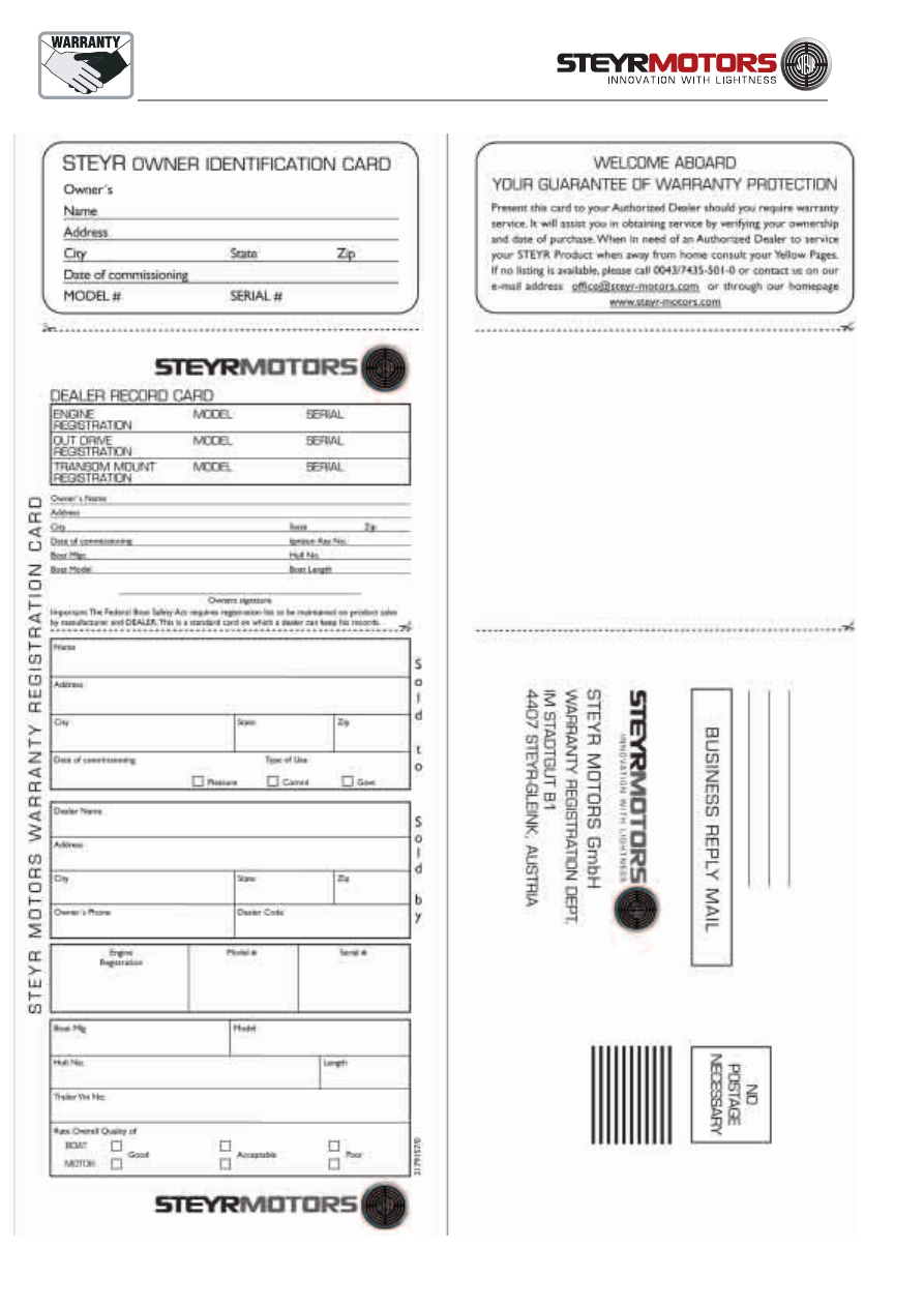
106

107
Appendix 1: Information about performing a monitoring on engine type MO266K43
Overload power monitoring through Engine Control Unit
This special engine features an automatic monitor overload power. The system
enables the driver to obtain overload power for a maximum of 6 minutes.
After this period the ECU will begin to lower the power to a continuous power
rating. The effect for the driver is a reduction in engine speed.
The reduction of speed is determined by the design of boat and propulsion unit,
and must be evaluated during the initial boat trials. The engine performance remains
at a continuous standard power rating, as long as the throttle is kept to max. position.
After operating the engine at part load or low load for more than 20 minutes, the
operator may resume to the monitored overload power.
The characteristic of overload power, continuous power and part load may vary
to some extend during operation. The ECU monitors the engine performance
during each phase of the operation and calculates the cycle of overload
performance and necessary part load phase. This means continued wide open
throttle operation of engine will result in a longer part load
run down period, for the overload power function to be regenerated.

108
AUSTRIA
STEYR MOTORS GmbH
Im Stadtgut B1, 4407 STEYR, AUSTRIA
Phone +43 7252 222 - 52
Fax +43 7252 222 - 29
e-mail:
service@steyr-motors.com
http://www.steyr-motors.com
SERVICE
NETWORK
A full list of our worldwide Service network can you found on our homepage under:
http://www.steyr-motors.com/distributors/distributors.htm
Wyszukiwarka
Podobne podstrony:
5 Operation and maintenance manual Alamarin jet Ver 1
5 Operation and maintenance manual Alamarin jet Ver 1
7 K4 FM operation maintenance manual
COMBAT AND OPERATIONAL STRESS CONTROL MANUAL FOR LEADERS AND SOLDIERS
Glow Worm installation and service manual Hideaway 70CF UIS
Glow Worm installation and service manual Ultimate 50CF UIS
Glow Worm installation and service manual Ultimate 60CF UIS
Glow Worm installation and service manual Glow micron 60
Optibelt Instalation and maintenance
An Introduction to Database Systems, 8th Edition, C J Date
Model Loading and stability manual
Glow Worm installation and service manual Glow micron 40
Glow Worm installation and service manual Hideaway 80BF UIS
Glow Worm installation and service manual Hideaway 50CF
Glow Worm installation and service manual Energy Saver 60 UI
Operation And Function Light Anti Armor Weapons M72 And M136 (2)
więcej podobnych podstron