
*FM 3-23.25
i
FIELD MANUAL
HEADQUARTERS
NO. 3-23.25 (FM 23-25)
DEPARTMENT OF THE ARMY
WASHINGTON, DC, 30 August 2001
LIGHT ANTIARM
OR WEAPONS
CONTENTS
Page
Preface................................................................................................................................iii
CHAPTER 1. INTRODUCTION
1-1. Types of Light Antiarmor Weapons.............................................1-1
1-2. Care and Handling........................................................................1-2
1-3. Destruction Procedures (Combat Only) .......................................1-2
1-4. Decontamination Procedures .......................................................1-3
1-5. Operating Temperatures...............................................................1-4
CHAPTER 2. M72-SERIES LAW, OPERATION AND FUNCTION
2-1. Description ...................................................................................2-1
2-2. Technical Data .............................................................................2-2
2-3. Ammunition .................................................................................2-2
2-4. Inspection .....................................................................................2-5
2-5. Firing Mechanism ........................................................................2-6
2-6. Sights............................................................................................2-7
2-7. Operation and Function..............................................................2-11
2-8. Misfire Procedures .....................................................................2-14
2-9. Restoration to Carrying Configuration.......................................2-14
CHAPTER 3. M136 AT4, OPERATION AND FUNCTION
3-1. Description ...................................................................................3-1
3-2. Technical Data .............................................................................3-2
3-3. Ammunition .................................................................................3-2
3-4. Inspection .....................................................................................3-4
3-5. Firing Mechanism, Safeties, and Weapon Function ....................3-5
3-6. Sights............................................................................................3-7
3-7. Operation......................................................................................3-8
3-8. Misfire Procedures .....................................................................3-11
3-9. Restoration to Carrying Configuration.......................................3-13
DISTRIBUTION RESTRICTION: Approved for public release; distribution is unlimited.
______________________________________________________
*This publication supersedes FM 23-25, 17 August 1994.

FM 3-23.25
ii
Page
CHAPTER 4. MARKSMANSHIP FUNDAMENTALS
4-1. Steady Hold..................................................................................4-1
4-2. Aiming Procedures.......................................................................4-1
4-3. Breath Control..............................................................................4-6
4-4. Trigger Manipulation ...................................................................4-6
4-5. Integrated Act of Shooting ...........................................................4-6
CHAPTER 5. FIRING POSITIONS
5-1. Standing Position .........................................................................5-1
5-2. Kneeling Position .........................................................................5-3
5-3. Sitting Position .............................................................................5-4
5-4. Prone Position ..............................................................................5-5
CHAPTER 6. COMBAT TECHNIQUES
6-1. Range Estimation .........................................................................6-1
6-2. Speed Estimation..........................................................................6-1
6-3. Armored Vehicle Weaknesses .....................................................6-2
6-4. Methods of Engagement...............................................................6-4
6-5. Engagement of Field Fortifications and Buildings ......................6-7
6-6. Engagement of Other Vehicles ....................................................6-7
6-7. Limited Visibility Engagements ..................................................6-9
6-8. Engagement in NBC Conditions ..................................................6-9
6-9. Engagement from an Enclosure ...................................................6-9
6-10. Engagement Beyond Maximum Effective Range
(M136 AT4 Only) ......................................................................6-10
6-11. Offensive Operations..................................................................6-10
6-12. Defensive Operations .................................................................6-11
6-13. Other Tactical Operations ..........................................................6-11
CHAPTER 7. TRAIN-THE-TRAINER AND UNIT TRAINING PROGRAMS
7-1. Train-the-Trainer Program ...........................................................7-1
7-2. Unit Training Program .................................................................7-2
7-3. Training Strategy..........................................................................7-4
APPENDIX A. SAFETY...............................................................................................A-1
APPENDIX B. TRAINING DEVICES AND AIDS..................................................... B-1
APPENDIX C. PERFORMANCE EVALUATIONS ................................................... C-1
APPENDIX D. SUGGESTED DESIGN FOR COMBINED LIGHT
ANTIARMOR RANGE.......................................................................D-1
APPENDIX E. FIRING TABLES AND EXAMPLE SCORECARDS........................ E-1
APPENDIX F. INFRARED LASER AIMING DEVICES ...........................................F-1
GLOSSARY.........................................................................................................Glossary-1
REFERENCES................................................................................................. References-1
INDEX ......................................................................................................................Index-1

FM 3-23.25
(FM 23-25)
30 AUGUST 2001
0122206
DISTRIBUTION:
Active Army, Army National Guard, and U. S. Army Reserve: To be distributed in
accordance with the initial distribution number 114321, requirements for FM 3-23.25.
By Order of the Secretary of the Army:
ERIC K. SHINSEKI
General, United States Army
Chief of Staff
Official:
JOEL B. HUDSON
Administrative Assistant to the
Secretary of the Army
FM 3-23.25
1-1
CHAPTER 1
INTRODUCTION
This chapter provides information common to the light antiarmor
weapons discussed in this manual. Topics include care and handling,
destruction and decontamination procedures, and operating temperatures.
Light antiarmor weapons are used against light armored vehicles, field
fortifications, or other similar targets. These weapons are issued as rounds
of ammunition to individual soldiers in addition to their assigned weapons
and the unit's organic antiarmor weapons. Light antiarmor weapons can
withstand extreme weather and environmental conditions, including arctic,
tropical, and desert. The light antiarmor weapons category includes both
light antiarmor and light antitank weapons.
1-1.
TYPES OF LIGHT ANTIARMOR WEAPONS
Light antiarmor weapons include the M72-series light antitank weapon (LAW) and the
M136 AT4. The M72-series LAW was designed in the early 1960's for use against light
tanks of that era (Figure 1-1). The M136 AT4 was designed in the late 1980's for use
against the improved armor of light armored vehicles (Figure 1-2).
Figure 1-1. M72-series light antitank weapon.
FM 3-23.25
1-2
Figure 1-2. M136 AT4 light antiarmor weapon.
1-2.
CARE AND HANDLING
Light antiarmor weapons are issued as rounds of ammunition. The only requirement for
their care is a visual inspection, outlined in the appropriate chapter for each weapon
(Chapter 2 for the LAW and Chapter 3 for the AT4).
1-3.
DESTRUCTION PROCEDURES (COMBAT ONLY)
In combat, live and expended light antiarmor weapons are destroyed only to prevent their
capture or use by the enemy and, even then, only on order. For such an order to be given,
the weapons must be so badly damaged that neither repairs nor cannibalization can
restore them to usable condition (FM 5-25). Table 1-1 provides destruction procedures
for live and expended light antiarmor weapons; Appendix A discusses safety precautions
to follow when destroying them.
DEMOLITION
Prepare a 113-gram (one-quarter pound) demolition
charge. Tape or tie the charge over the propellant
charge. Dual prime the charge to reduce the chance of
a misfire.
BURNING
Construct a pit or trench deep enough to allow 0.6
meter (2 feet) of space between the weapons and the
top surface of the ground. Place combustible material
such as wood, paper, or rags in the pit, then place the
weapon inside, pointed into the side of the pit and
directed away from all friendly soldiers. Pour diesel fuel
or oil over the weapons and the combustible material.
LIVE
LIGHT
ANTIARMOR
ROUND
FIRING
If time does not permit use of the previous methods,
dispose of the weapons by firing them randomly in the
direction of the enemy. Before using this method,
observe all appropriate safety requirements.
DANGER
TO AVOID POSSIBLE INJURY OR DEATH, MOVE TO A
SAFE POSITION AND TAKE COVER BEFORE USING
ANY DESTRUCTION PROCEDURE. BEFORE USING
DEMOLITIONS FOR ANY REASON, YOU MUST KNOW
THE PROPER PROCEDURES IN FM 5-25.
Table 1-1. Destruction procedures for light antiarmor weapons.

FM 3-23.25
1-3
MECHANICAL
Though you must never use mechanical means to
destroy live antiarmor weapons or expended M136
AT4s, you may do so to destroy the residue from an
expended M72-series LAW. For example, you can drive
over it with a tracked vehicle or strike it with a pick, ax,
or other object, as long as you make it unusable.
DEMOLITION
Same as a live round.
EXPENDED
LIGHT
ANTIARMOR
ROUND
BURNING
Same as a live round.
Table 1-1. Destruction procedures for light antiarmor weapons (continued).
1-4.
DECONTAMINATION PROCEDURES
The soldier can use his M258A1 or DKIE (XM280) individual decontamination packet to
remove H-series, G-series, and V-series agents. FM 3-5 provides more information about
decontamination procedures for equipment and weapons.
DANGER
1. WHEN USING FIRE TO DESTROY A LIGHT ANTIARMOR
WEAPON, THE TIME REQUIRED TO EXPLODE THE
WARHEAD IS UNPREDICTABLE. ALSO, IGNITING THE
PROPELLANT CAN CAUSE IT TO FIRE THE WARHEAD IN
ANY DIRECTION, WHICH COULD IN TURN CAUSE INJURY
OR DEATH.
2. OBSERVE THE APPROPRIATE SAFETY PRECAUTIONS
WHEN HANDLING DIESEL FUEL. CARELESSNESS COULD
CAUSE PAINFUL, EVEN FATAL, BURNS.
3. DO NOT TRY TO USE VEHICLES OR MECHANICAL MEANS
TO DESTROY LIVE ANTIARMOR WEAPONS. EITHER METHOD
COULD DETONATE THE WARHEAD OR PROPELLANT
CHARGE, WHICH COULD CAUSE INJURY OR DEATH.
DANGER
NEVER USE DS2 TO DECONTAMINATE ANY LIGHT
ANTIARMOR WEAPON. THE DS2 WOULD DISSOLVE THE
RUBBER AND PLASTIC SEALS, ALLOWING THE DS2 TO
REACH THE PROPELLANT AND PRODUCING AN
EXTREMELY HAZARDOUS MIXTURE

FM 3-23.25
1-4
1-5.
OPERATING TEMPERATURES
Operating temperatures for the M72-series LAW and M136 AT4 are -40 degrees to 140
degrees Fahrenheit (-40 degrees to 60 degrees Centigrade). Firing light antiarmor
weapons in temperatures outside these limits could cause a misfire or produce some other
hazard for the soldier (Appendix A).
FM 3-23.25
2-1
CHAPTER 2
M72-SERIES LAW, OPERATION AND FUNCTION
This chapter provides information on and technical data for the
M72-series light antitank weapon (LAW). It also discusses the
characteristics, nomenclature, functioning, and operation of the LAW.
2-1.
DESCRIPTION
The M72-series LAW is a lightweight, self-contained, antiarmor weapon consisting of a
rocket packed in a launcher (Figure 2-1). It is man-portable, may be fired from either
shoulder, and is issued as a round of ammunition. It requires little from the user
only a
visual inspection and some operator maintenance. The launcher, which consists of two
tubes, one inside the other, serves as a watertight packing container for the rocket and
houses a percussion-type firing mechanism that activates the rocket.
a. Outer Tube. The trigger housing assembly (which contains the trigger assembly)
is on the upper surface of the outer tube. So are the trigger arming handle, front and rear
sight assemblies, and the launcher's rear cover.
b. Inner Tube. The inner tube telescopes outward toward the rear, guided by a
channel assembly that rides in an alignment slot in the outer tube's trigger housing
assembly. The channel assembly also houses the firing pin rod assembly, which includes
a detent lever assembly. The detent lever assembly moves under the trigger assembly in
the outer tube, locking the inner tube in the extended position and cocking the weapon.
All this must occur before the weapon can be fired.
c. Rocket. The rocket is a percussion-ignited, fin-stabilized, fixed munition. The
rocket is attached by the igniter to the inside of the launcher. The rocket consists of a
66-mm HEAT warhead, a point-initiating, base-detonating fuze, and a rocket motor. Six
spring-loaded fins are attached to the rear of the rocket motor. These fins are folded
forward along the motor when the rocket is in the launcher. When ignited, the propellant
in the rocket motor burns completely, producing gasses about 1,400 degrees Fahrenheit
(760 degrees Centigrade). The gas pressure pushes the rocket toward the target and exits
to the rear of the launcher as the backblast.
Figure 2-1. The M72A2 or M72A3 LAW.
FM 3-23.25
2-2
2-2.
TECHNICAL DATA
The following data apply to the M72A2 and M72A3 LAWs:
a. Launcher.
Length (Extended).................................................Less than 1 meter (34.67 inches)
Length (Closed).................................................................. 0.67 meter (24.8 inches)
Weight (Complete M72A2)........................................................2.3 kg (5.1 pounds)
Weight (Complete M72A3)........................................................2.5 kg (5.5 pounds)
Firing Mechanism ....................................................................................Percussion
Front Sight.....................................Reticle graduated in 25-meter range increments
Rear Sight.......................... Peep sight adjusts automatically to temperature change
b. Rocket.
Caliber ............................................................................................................ 66 mm
Length........................................................................................ 50.8 cm (20 inches)
Weight ........................................................................................1.8 kg (2.2 pounds)
Muzzle
Velocity.........................................................................144.8 mps (475 fps)
Minimum Range (Combat) .........................................................10 meters (33 feet)
Minimum
Arming
Range ............................................................10 meters (33 feet)
Maximum Range ...............................................................1,000 meters (3,300 feet)
Maximum Effective Ranges:
Stationary Target ...............................................................200 meters (660 feet)
Moving Target ...................................................................165 meters (541 feet)
(Beyond these ranges, there is less than a fifty percent
chance of hitting the target.)
2-3.
AMMUNITION
The M72-series LAW is issued as a round of ammunition. It contains a nonadjustable
propelling charge and a rocket. Every M72-series LAW has an integral high-explosive
antitank (HEAT) warhead. The warhead is in the rocket's head (or body) section. The
fuze and booster are in the rocket's closure section. The propellant, its igniter, and the fin
assembly are in the rocket's motor. No inert versions are available (Figure 2-2).
Appendix B provides information about appropriate gunnery training devices and
ammunition. Although the M72-series LAW is mainly used as an antiarmor weapon, it
may be used with limited success against secondary targets such as gun emplacements,
pillboxes, buildings, or light vehicles. (Chapter 6 provides more information about
combat techniques.)
Figure 2-2. High-explosive antitank rocket (ammunition).
FM 3-23.25
2-3
a. Description. The 66-mm HEAT rocket warhead consists of a tapered, thin-gauge
steel body. When it explodes, the force and heat of the explosive focus into a small but
powerful gas jet. This directional jet penetrates the target and, if the target is a vehicle,
sprays molten metal inside. If the jet hits an engine or ammunition, it may start a fire or
cause an explosion. Figure 2-3 shows how the warhead penetrates 300 millimeters of
rolled homogeneous steel armor.
(1) Impact. The nose cone crushes; the impact sensor activates the fuze.
(2) Ignition. The ogive crush switch activates the electric detonator. The booster
detonates, initiating the main charge.
(3) Penetration. The main charge fires and forces the warhead body liner into a
directional gas jet that penetrates armor plate.
(4) After Armor Effects (Spalling). The projectile fragments and incendiary effects
produce blinding light and destroy the target's interior.
Figure 2-3. Effects of M72-series LAW warhead.
b. Characteristics. The head of the round is olive drab stenciled in yellow. The
M412 fuze is dropsafe and boresafe. Its minimum arming distance is about 33 feet
(10 meters). Six stabilizing fins are attached as part of the motor. As the rocket clears the
launcher, springs force open the fins, which stabilize the rocket in flight.
c. Packaging. Five complete M72-series LAWs are packaged within a fiberboard
inner pack for a total weight of 12.5 kilograms (27 1/2 pounds). Three inner packs are
then placed in a wire-bound wooden box, the gross weight of which is 54.5 kilograms
(120 pounds) (Figure 2-4, page 2-4).
FM 3-23.25
2-4
Figure 2-4. Packaging for M72-series LAW.
2-4.
INSPECTION
Because the M72-series LAW is issued as a round of ammunition rather than as a
weapon, inspection is limited to a visual examination of the sealed unit.
Inspect the launcher's overall condition before preparing the launcher for use.
•
Check the body for dents, cracks, or bulges.
•
Check the rubber boots covering the trigger bar and barrel detent for tears or
punctures.
•
Ensure the arming handle is present and on SAFE and that the pull pin is in
place.
FM 3-23.25
2-5
•
Check the data plate for the phrase, W/COUPLER (Figure 2-5).
Figure 2-5. Launcher data plate.
DANGER
1. IF THE M72A2 LAW DOES NOT STATE "W/COUPLER" ON ITS
DATA PLATE, TURN THE WEAPON IN TO THE UNIT
AMMUNITION SECTION.
2. THE COUPLER PREVENTS THE INNER AND OUTER TUBES
FROM SEPARATING AND POSSIBLY CAUSING PREMATURE
DETONATION.
FM 3-23.25
2-6
2-5.
FIRING MECHANISM
The firing mechanism includes the trigger arming handle, the trigger assembly, and the
firing pin rod assembly (Figure 2-6).
Figure 2-6. Firing mechanism.
a. Trigger Arming Handle. The trigger arming handle is located forward of the
trigger bar and has two positions: SAFE and ARM. Leave the trigger arming handle on
SAFE until the launcher is in the correct firing position (Figure 2-7). To press the trigger,
you must first pull the arming handle forward and lock it in the ARM position.
b. Trigger Assembly. The trigger assembly is on the top rear of the outer tube. To
fire the launcher, press downward on the trigger bar.
Figure 2-7. Trigger arming handle.
c. Firing Pin Rod Assembly. The rear sight cover and the firing pin housing are on
the top of the rear of the inner tube. Inside the housing, the primer and the firing pin rod
are aligned (Figure 2-8). Pressing the trigger bar releases the tension on the firing pin rod
assembly, allowing the firing pin to strike the center of the primer.
FM 3-23.25
2-7
Figure 2-8. Firing pin, primer, and propellant charge.
2-6.
SIGHTS
This paragraph discusses the front and rear sights and their proper use.
a. Front Sight, M72A2 and M72A3 LAWs. The front sight has a raised vertical
range line marked with ranges from 50 to 350 meters in 25-meter increments
(Figure 2-9). Two curved stadia lines are etched on the front sights. Do not use the stadia
lines on this sight to estimate range, because they are inaccurate. Lead indicators are
located on either side of the stadia lines to help you engage moving targets. On the
M72A3, use the front sight illuminated range marks at the 100-meter and 150-meter
points to help you engage targets in low light.
WARNING
DO NOT TOUCH THE RANGE MARKS; THEY ARE ILLUMINATED
WITH PROMETHIUM, WHICH IS MILDLY RADIOACTIVE.
FM 3-23.25
2-8
Figure 2-9. Front sight, M72A2 and M72A3 LAWs.
b. Rear Sight, M72A2 and M72A3 LAWs. The rear sight consists of a steel bracket
with a rubber boot and plastic peep sight. This sight automatically adjusts to changes in
temperature (Figure 2-10), which means that its settings are unaffected by temperature.
Figure 2-10. Rear sight, M72A2 and M72A3 LAWs.
c. AN/PVS-4 Nightsight. This nightsight is issued with various accessories,
including a bracket that, when mounted on an M72-series LAW, will allow you to use an
AN/PVS-4 on the LAW. However, this works only if DS maintenance has already
installed an M72A1 reticle in the AN/PVS-4. Though the reticle was developed for the
M72A1 LAW, you can also use it with the other M72-series models. To mount the
M72A1 bracket assembly on any M72-series LAWC
FM 3-23.25
2-9
(1) Place the bracket assembly on top of the rocket launcher (Figure 2-11) so that the
square cutout in the top of the bracket fits over the extension release button.
(2) Swing the lower adapter section up and under the rocket launcher and secure it by
turning the locking latch clockwise to fully engage the latch shoulder screw.
(3) Place the sight in the groove on the bracket and align the threaded screw hole in
the base of the sight with the lever screw assembly. Tighten the lever screw assembly
firmly.
Figure 2-11. Installing M72A1 mounting bracket assembly.
(4) Use the M72A1 reticle to estimate the range to a 20-foot target such as a tank
viewed from the side (Figure 2-12). Place the sight so that the rear and front of a flanking
target fit between the curved vertical lines (Figure 2-13). When you read the range from
the scale, note that the width of the tank is about one-half the tank's length. This means
you can estimate the range to a target, whether it is headed straight toward you or straight
away from you, by placing its sides between the curved vertical lines and halving the
range shown at that point. The bottom of each vertical line in the center of the reticle
FM 3-23.25
2-10
corresponds to an additional 25 meters. The length of a horizontal line represents 5 mils,
and the spaces between lines represent 5 mils. Use the stadia lines to estimate range only
when using the AN/PVS-4's M72A1 reticle pattern.
Figure 2-12. M72A1 reticle. Figure 2-13. Using M72A1
stadia lines to engage targets.
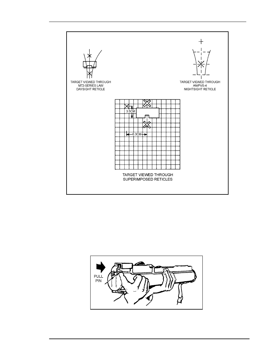
(5) Align the nightsight's reticle pattern to the LAW sights only once. After that, you
can move the nightsight from LAW to LAW without having to realign it each time
(Figure 2-14). To align the sight reticle pattern to the LAW sights, place a target at
25 meters. Install the mounting bracket and sight, and select a stable firing position for
the LAW. Turn both the TUBE BRIGHTNESS and RETICLE BRIGHTNESS knobs ON.
Align the 200-meter range mark on the daysight with the aiming point on the target.
Without moving the LAW, adjust the nightsight reticle so that its 200-meter range mark
coincides with an aiming point 6.3 centimeters left and 3.5 centimeters above the target
aiming point.
DANGER
IF YOU CANNOT FIND AN EMPTY LAUNCHER TO USE
TO ALIGN THE NIGHTSIGHT, YOU MAY USE AN
UNFIRED LAUNCHER, BUT THIS IS EXTREMELY
DANGEROUS.
FM 3-23.25
2-11
Figure 2-14. M72A1 alignment target for the AN/PVS-4.
2-7.
OPERATION AND FUNCTION
Before preparing the launcher for use, the firer inspects its overall condition.
a. To extend the rocket launcher
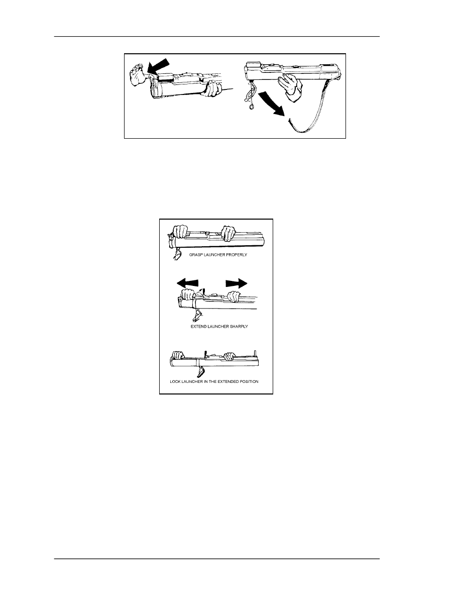
(1) Remove the pull pin and rotate the rear cover downward so the front cover and
adjustable sling assembly can fall free (Figures 2-15 and 2-16, page 2-11). Do not discard
the sling assembly until after you fire the rocket.
Figure 2-15. Removing the pull pin.
FM 3-23.25
2-12
Figure 2-16. Removing the front cover and the adjustable sling assembly.
(2) With your firing hand, grasp the rear sight cover; with your nonfiring hand, grasp
the launcher forward of the barrel detent. Pull your hands sharply in opposite directions
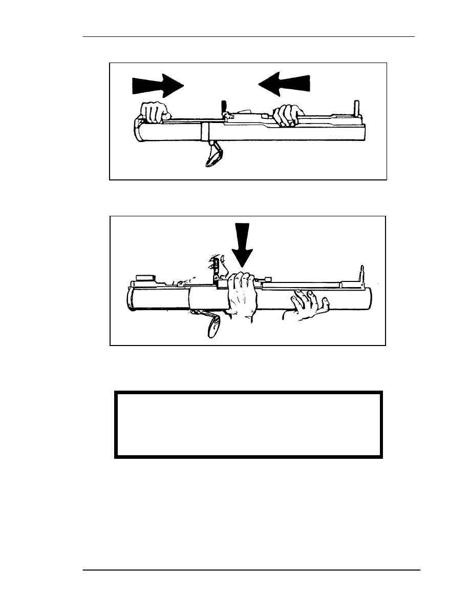
to extend the launcher (Figure 2-17). To ensure the launcher is fully extended and locked,
try to close it (Figure 2-18).
Figure 2-17. Extending the launcher.
b. To fire the rocket launcher, raise it slightly above shoulder level, rotate your body
under it, and place it on your shoulder. Check the backblast area, pull the trigger arming
handle to the ARM position, aim the launcher, and depress the rubber boot on the trigger
bar firmly to ensure the launcher fires (Figure 2-19). (If the trigger arming handle will not
remain in the ARM position, the launcher is not fully extended.) Pressing the trigger bar
causes the firing pin to strike the primer, which ignites the black powder in the flash tube,
which in turn ignites the propellant in the rocket motor.
FM 3-23.25
2-13
Figure 2-18. Ensuring launcher is locked in the extended position.
Figure 2-19. Firing the launcher.
2-8.
MISFIRE PROCEDURES
A misfire is a complete failure to fire caused by a procedural or mechanical failure.
Which misfire procedures should be used depends on whether the firer is in a combat or
training environment.
a. Causes. A misfire is usually caused by one of the following factors:
•
The launcher may not be fully extended.
DANGER
WHEN OPERATING THE LAW, KEEP IT POINTED
DOWNRANGE. ENSURE YOUR WHOLE BODY IS CLEAR
OF THE MUZZLE AND REAR OF THE LAUNCHER, AND
ENSURE THE BACKBLAST AREA IS CLEAR.

FM 3-23.25
2-14
•
The trigger arming handle may not be armed.
•
The firing mechanism or the propelling charge explosive train may be faulty.
b. Combat Environment. If a misfire occurs in combat
(1) Squeeze the trigger again immediately.
(2) If the launcher still fails to fire, place the trigger arming handle on SAFE.
(3) Partly collapse the launcher, then extend it to cock it again.
(4) Place it on your shoulder, check the backblast area again, then arm, aim, and fire.
(5) If the LAW still fails to fire, squeeze the trigger again and return the trigger
arming handle to SAFE. Collapse the launcher, set it aside, and try another one. As soon
as you can, dispose of the misfired LAW in accordance with SOP.
c. Training Environment. If an M72A2, M72A3, or M190 subcaliber device
misfires on a live-fire training range―
(1) Squeeze the trigger again.
(2) If the launcher still fails to fire, keep the launcher on your shoulder, announce
"Misfire," and wait 10 seconds. Place the trigger arming handle on SAFE.
(3) Move the launcher from your shoulder and wait one minute.
(4) Extend the launcher to cock it again, check the backblast area, place the launcher
back on your shoulder, pull the arming handle to the ARM position, aim, and squeeze the
trigger bar.
(5) If the launcher again fails to fire, wait 10 seconds before returning the trigger
arming handle to the SAFE position.
(6) Keep the launcher trained on the target area at least one minute; DO NOT
collapse the launcher.
(7) Move the launcher to a safe area and dispose of it IAW unit SOP.
2-9.
RESTORATION TO CARRYING CONFIGURATION
If the launcher is prepared to fire, but then is not fired, it should be returned to the
carrying configuration by reversing the preparation procedure. After the launcher has
been prepared for firing, it is no longer watertight. Therefore, when carrying the launcher,
sling it over either shoulder with the muzzle (forward) end down. Only the rocket and
rocket motor ignition system are waterproof.
a. Return the trigger arming handle to the SAFE position.
b. Remove the launcher from your shoulder, depress the barrel detent, collapse the
launcher tube, and guide the front and rear sights into position.
c. Close the rear cover, replace the cover pull pin, and replace the sling assembly.
WARNING
KEEP YOUR WEAPON POINTED TOWARD THE
TARGET.
WARNING
TO PREVENT INJURY, REMOVE YOUR THUMB
FROM THE DETENT AFTER COLLAPSING THE
LAUNCHER 1/2 TO 1 INCH.
FM 3-23.25
3-1
CHAPTER 3
M136 AT4, OPERATION AND FUNCTION
This chapter provides information and technical data for the M136
AT4 light antiarmor weapon, including its characteristics, nomenclature,
and operation. Its function, firing mechanism, and safeties are also
discussed.
3-1.
DESCRIPTION
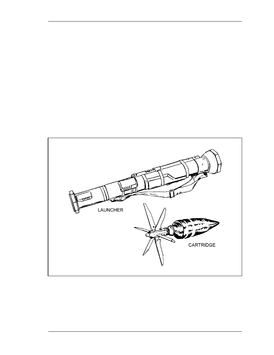
The M136 AT4 is a lightweight, self-contained, antiarmor weapon. It consists of a free-
flight, fin-stabilized, rocket-type cartridge packed in an expendable, one-piece,
fiberglass-wrapped tube (Figure 3-1). The M136 AT4 is man-portable and is fired from
the right shoulder only. The launcher is watertight for ease of transportation and storage.
Though the M136 AT4 can be employed in limited visibility, the firer must be able to see
and identify the target and estimate the range to it. Unlike the M72-series LAW, the
M136 AT4 launcher need not be extended before firing.
Figure 3-1. Launcher and HEAT cartridge.
FM 3-23.25
3-2
3-2.
TECHNICAL DATA
The following data apply to the M136 AT4:
a. Launcher.
Length..................................................................................... 1,020 mm (40 inches)
Weight (Complete System) ......................................................6.7 kg (14.8 pounds)
Rear Sight.................................Range indicator, graduated in 50-meter increments
b. Rocket.
Caliber ............................................................................................................ 84 mm
Muzzle Velocity ...........................................................................290 mps (950 fps)
Length........................................................................................ 460 mm (18 inches)
Weight ...........................................................................................1.8 kg (4 pounds)
Minimum Range
Training ...................................................................................30 meters (100 feet)
Combat ......................................................................................10 meters (33 feet)
Arming ......................................................................................10 meters (33 feet)
Maximum Range ...............................................................2,100 meters (6,890 feet)
Maximum Effective Range .....................................................300 meters (985 feet)
3-3.
AMMUNITION
The M136 AT4 is a round of ammunition with an integral, rocket-type cartridge. The
cartridge consists of a fin assembly with tracer element; a point-initiating, base-
detonating, piezoelectric fuze; a warhead body with liner; and a precision-shaped
explosive charge (Figure 3-2).
Figure 3-2. 84-mm HEAT cartridge.
a. Description. The M136 AT4's warhead has excellent penetration ability and
lethal after-armor effects. The extremely destructive, 440 gram shaped-charge explosive
penetrates more than 14 inches (35.6 cm) of armor. Warhead effects are shown in
Figure 3-3.
FM 3-23.25
3-3
(1) Impact. The nose cone crushes; the impact sensor activates the fuze.
(2) Ignition. The piezoelectric fuze element activates the electric detonator. The
booster detonates, initiating the main charge.
(3) Penetration. The main charge fires and forces the warhead body liner into a
directional gas jet that penetrates armor plate.
(4) After-Armor Effects (Spalling): The projectile fragments and incendiary effects
produce blinding light and destroy the interior of the target.
Figure 3-3. Effects of M136 AT4 warhead.
b. Packaging. Five M136 AT4s, each wrapped in a plastic barrier bag, are packed
together in a wooden container. The containers are too heavy to stack more than four
deep on the pallets (Figure 3-4).
Figure 3-4. Ammunition packaging and markings.
FM 3-23.25
3-4
c. Color-Coding. M136 AT4 launchers are marked with color-coded bands
(Figure 3-5). A black with yellow band indicates an HE antiarmor round (early models
had a solid black band). A gold or yellow band indicates a field handling trainer; no band
indicates an M287 9-mm tracer bullet trainer (Appendix B).
Figure 3-5. Location of color-coded band.
3-4.
INSPECTION
Since the M136 AT4 is issued as a round of ammunition rather than as a weapon, the
launcher is completely sealed. However, its overall condition should be inspected at the
time of issue and again before use (Figure 3-6). The wooden container should be opened,
the plastic bags removed, and the launcher visually inspected for obvious damage. If the
M136 AT4 is not to be used immediately, it should be returned to its plastic bag and the
bag resealed with tape. The soldier issued the weapon must ensure
•
The rear seal, a brown acrylic plastic plate inside the venturi, is in place and
undamaged.
•
The transport safety pin is in place and fully inserted. The lanyard is attached to
the transport safety pin and the launcher. The lanyard should already be wrapped
around the launcher clockwise and the transport safety pin inserted in the retainer
hole counterclockwise.
•
The cocking lever is present and in the SAFE (uncocked) position.
•
The plastic fire-through muzzle cover is in place and undamaged. If it is torn or
broken, cut it out and check the launch tube to ensure it is clear of foreign objects.
Remove any that you find by turning the tube muzzle downward and gently
shaking the launcher.
•
The launcher has the correct color-coded band.
•
The sights function properly. Open the sight covers to ensure the sights pop up
and are undamaged.
•
The forward safety does not move when you depress it.
•
The red trigger button is not missing.
•
The launcher body has no cracks, dents, or bulges.
•
The carrying sling is not frayed and is attached firmly to the launch tube.
•
The shoulder stop is not broken or damaged, and it unsnaps and folds down.
FM 3-23.25
3-5
Figure 3-6. Inspection.
3-5.
FIRING MECHANISM, SAFETIES, AND WEAPON FUNCTION
The function of the M136 AT4 must be discussed along with its firing mechanism and
safety features. The firing mechanism is mechanical and consists of a red trigger button,
an enclosed firing rod and spring, and three safety devices (Figure 3-7). The first safety
device is the transport safety pin. The red trigger button is located between the other two,
the cocking lever and the forward safety. The weapon cannot be fired until all three
safeties have been disengaged.
a. Transport Safety Pin. This pin blocks the firing pin from striking the cartridge
percussion cap. To disengage this pin, pull it outward, then release it.
Figure 3-7. Firing mechanism and transport safety pin.
FM 3-23.25
3-6
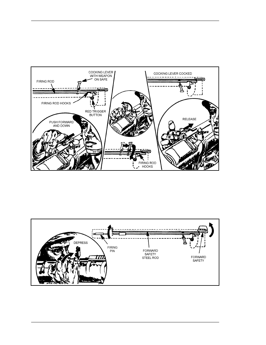
b. Cocking Lever. When this lever, which is attached to the firing rod (Figure 3-8),
is in the SAFE position, the firing rod and the trigger cannot touch. To cock the AT4,
push the lever forward and rotate it downward and to the right with your right thumb.
This causes the hooks on the front of the firing rod to catch and hold the red trigger
button.
Figure 3-8. Cocking lever.
c. Forward Safety. This safety is on the front end of the firing mechanism
(Figure 3-9) and is connected to a steel rod with a bent end that blocks the firing rod from
striking the firing pin. To fire the M136 AT4, hold down the forward safety so the firing
rod can strike the percussion cap and ignite the propellant when you push the trigger.
Figure 3-9. Forward safety.
FM 3-23.25
3-7
3-6.
SIGHTS
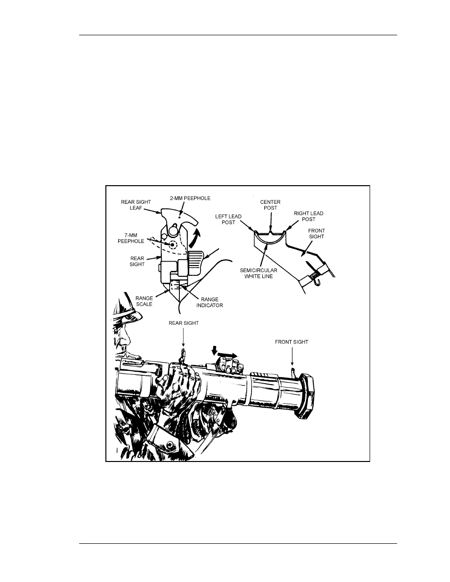
The fact that the AT4's front and rear sights resemble those of the M16-series rifle makes
using the AT4 easier (Figure 3-10).
a. Front Sight. The front sight has a sight blade with a center post and left and right
lead posts. A semicircular white line helps you obtain the proper sight picture. To open
the front sight cover, press down on it and slide it backward until the sight pops up.
b. Rear Sight. The rear sight has a sight blade, range adjustment knob, range scale,
2-mm peephole for normal daylight visibility conditions, and 7-mm peephole for limited
visibility conditions. To open the rear sight cover, press down on it and slide it forward
until the sight pops up.
c. Nightsight. The AT4 can be fitted with the AN/PAQ-4C, AN/PEQ-2, or the
AN/PAS-13, when used with the nightsight mounting bracket (NSN 5340-01-391-3004).
Figure 3-10. Sights.
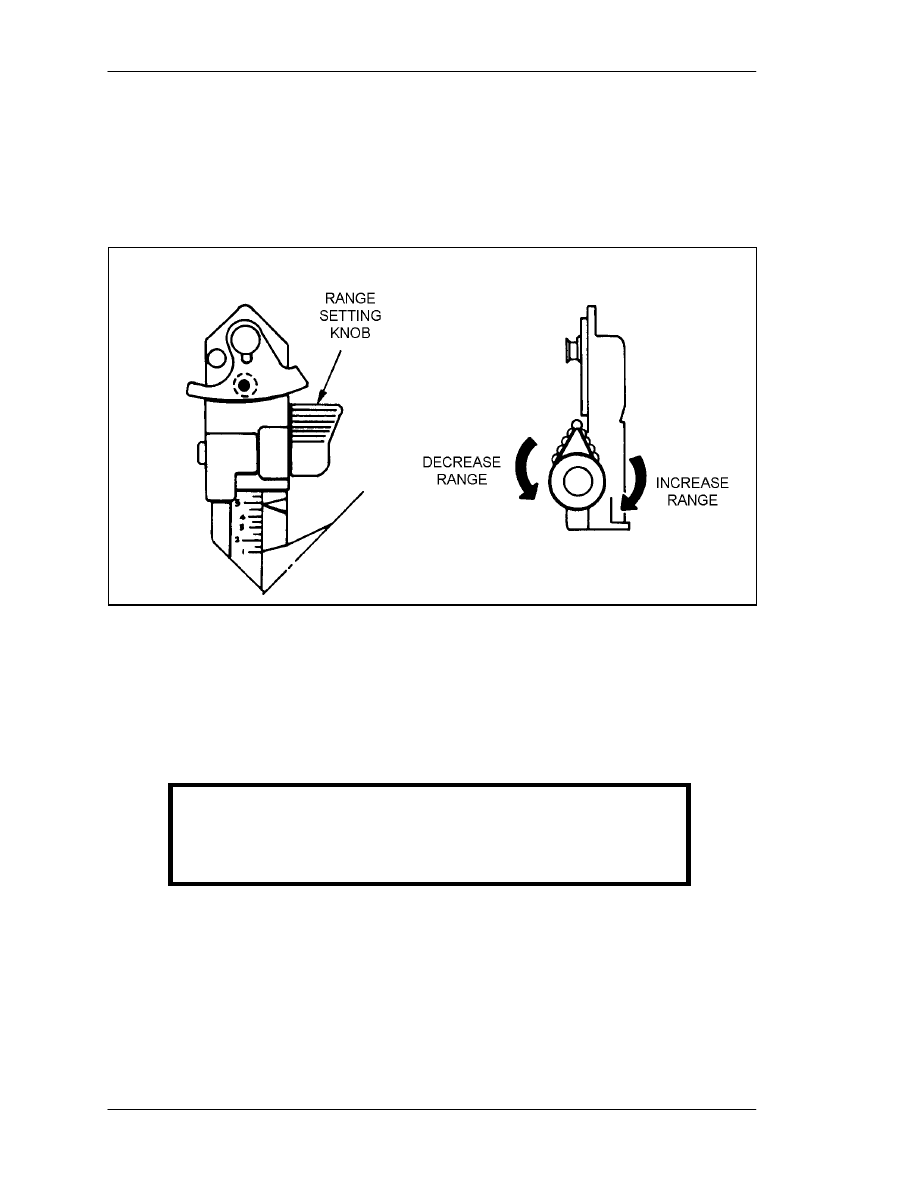
(1) The leaf blade that covers the 7-mm peephole has its own tiny 2-mm peephole. To
uncover the 7-mm peephole, pull the bottom of the leaf blade out slightly and rotate it
right and up. To cover the 7-mm peephole, rotate it back down and ensure the leaf blade
FM 3-23.25
3-8
is seated. The range indicator scale is indexed from 100 to 500 meters in 50-meter
increments.
(2) To increase the range setting beyond 200 meters, turn the range adjustment knob
clockwise, or vice versa (Figure 3-11). You must remember to reset the range to
200 meters when you close the rear sight. Otherwise, closing the sight cover will break
off the rear sight.
Figure 3-11. Adjusting the rear sight range setting.
3-7.
OPERATION
If you are under fire, take cover before preparing the M136 AT4 for firing as follows:
a. Remove the AT4 from its carrying position and cradle it in your left arm
(Figure 3-12).
WARNING
Insert the approved brand of earplugs before you fire.
Keep the weapon pointed toward the target, and keep the
backblast area clear.
FM 3-23.25
3-9
Figure 3-12. Cradle position.
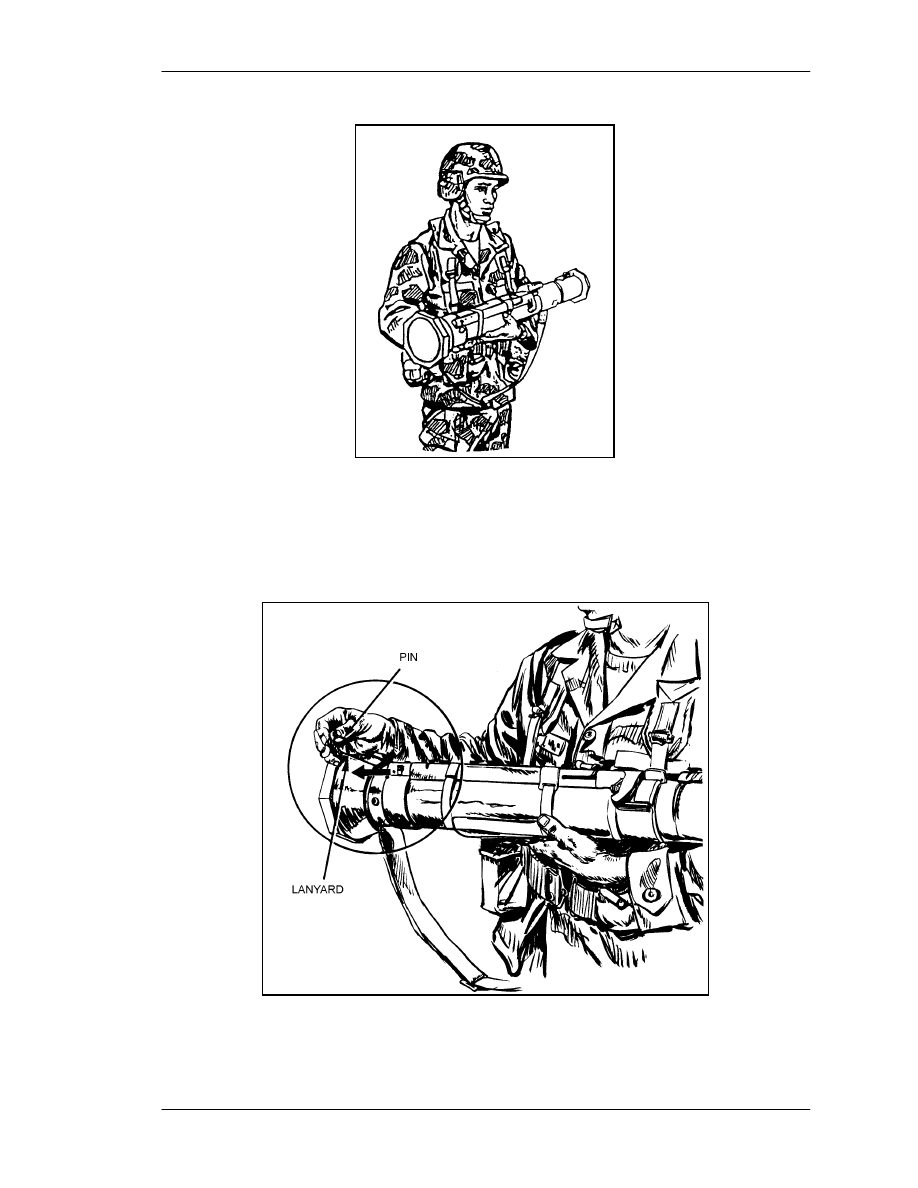
b. With your right hand, pull and release the transport safety pin (Figure 3-13). This
pin is important
you must reinsert it if you do not fire the launcher. Therefore, unless it
is attached to the launcher with a lanyard, you must keep it in a safe place.
Figure 3-13. Removing the transport safety pin.
FM 3-23.25
3-10
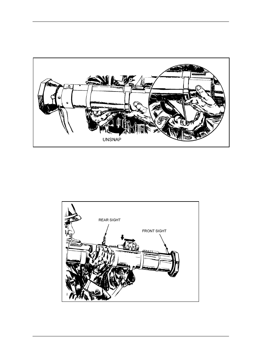
c. Unsnap, unfold, and hold the shoulder stop with your right hand (Figure 3-14).
d. Place the launcher on your right shoulder and stabilize it by grasping the sling
near the launcher's muzzle with your left hand.
Figure 3-14. Unsnapping the shoulder stop.
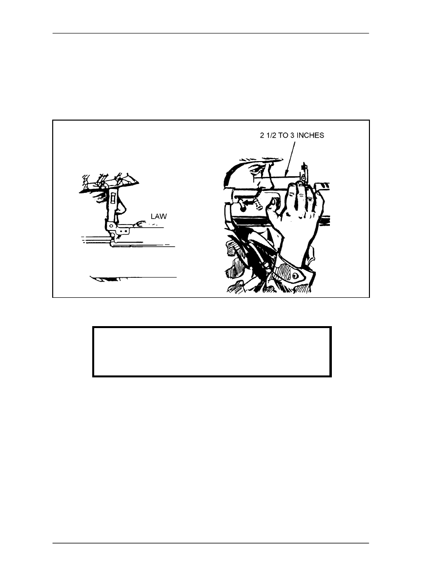
e. With the AT4 on your right shoulder, stabilize it with your left hand and open the
sights with your right hand. Press down and pull backward on the front sight cover until
the front sight pops up (Figure 3-15), then press down and forward on the rear sight cover
until the rear sight pops up. The rear sight should be no less than 2 1/2 inches and no
more than 3 inches from your eyes.
Figure 3-15. Opening and adjusting the sights.
FM 3-23.25
3-11
f. Set the rear sight for the correct range to the target.
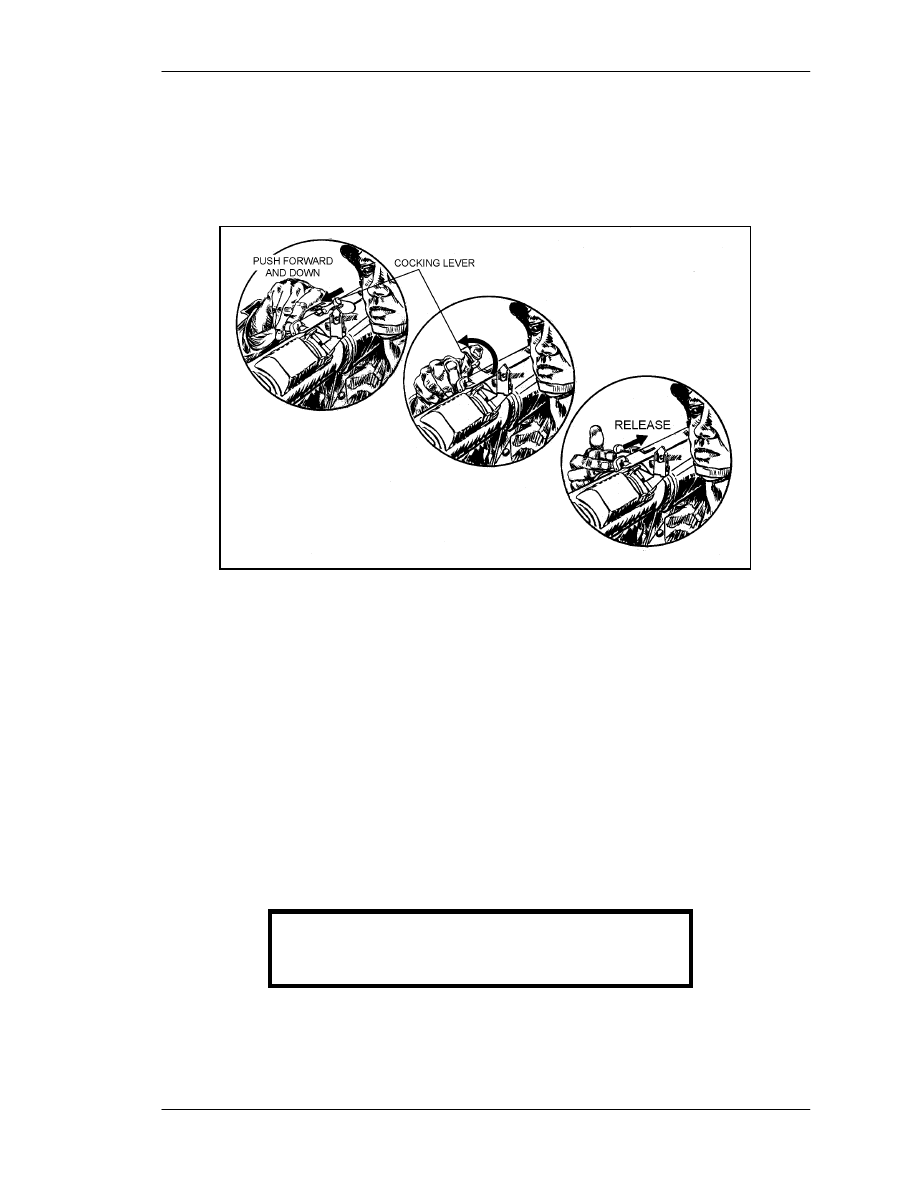
g. Check the backblast area before you cock the launcher. Then, with your right
hand, unfold the cocking lever (Figure 3-16). Place your thumb under it and, with the
support of your fingers in front of the firing mechanism, push it forward, rotate it
downward and to the right, and let it slide backward.
Figure 3-16. Cocking the launcher.
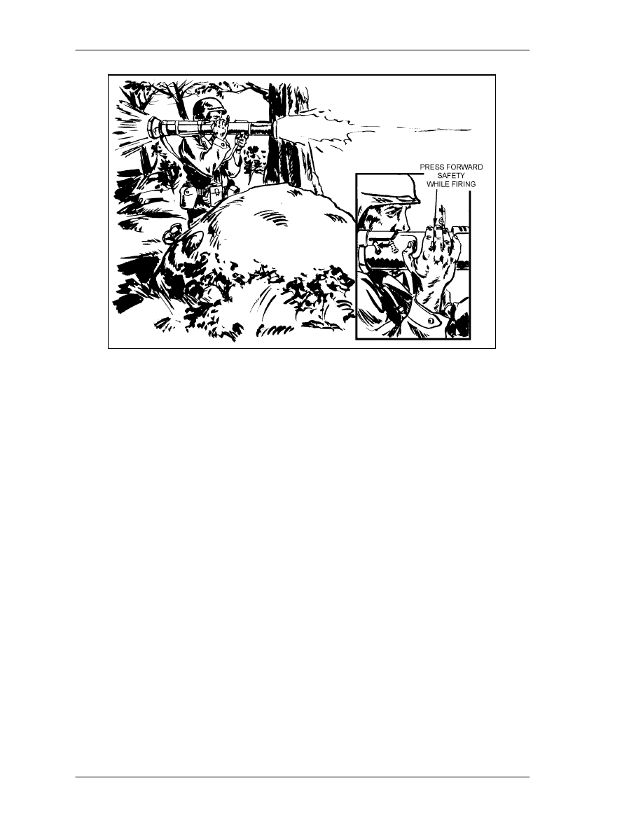
h. Pull back on the sling with your left hand to seat the shoulder stop firmly against
your shoulder. To avoid a misfire, use the index and middle fingers on your right hand to
hold the forward safety down and to the left while you fire (Figure 3-17, page 3-12).
3-8.
MISFIRE PROCEDURES
A misfire is a complete failure to fire caused by a procedural or mechanical failure.
Which misfire procedures should be used depends on whether the firer is in a combat or
training environment.
a. Causes. A misfire is usually caused by one of the following factors:
The forward safety is not depressed far enough to disengage the safety.
The firing mechanism is faulty.
The propelling charge explosive train is faulty.
WARNING
Keep your weapon pointed toward the target.
FM 3-23.25
3-12
Figure 3-17. Firing the launcher.
b. Combat Environment. If a misfire occurs in combat
(1) Release the forward safety.
(2) Remove your right hand from the firing mechanism and cock the weapon again.
(3) Try to fire again. If the launcher still does not fire, maintain the same firing
position and return the cocking lever to the SAFE (uncocked) position.
(4) Move the launcher from your shoulder, keeping the launcher pointed toward the
enemy. Reinsert the transport safety pin.
(5) In combat, break off the sights to identify the misfired launcher. In training,
however, you would not want to damage the field handling trainer (FHT), so identify the
misfired launcher simply by leaving the sights up.
(6) Place the launcher on the ground, pointed toward the enemy, and use another
launcher. As soon as you can, dispose of the misfired launcher IAW unit SOP.
c. Training Environment. If a misfire occurs on a live-fire training range, the
soldier responds as follows (the trainer later disposes of the launcher IAW local SOP):
(1) Shouts "Misfire" as soon as the launcher fails to fire while maintaining the
original sight picture.
(2) Releases the forward safety.
(3) Recocks the launcher: Immediately removes his right hand from the firing
mechanism and pushes the cocking lever forward with the heel of his right hand until the
lever locks with a loud clicking noise.
NOTE:
Because performing immediate action takes so little time, you need not recheck
the backblast area.

FM 3-23.25
3-13
(4) Press the forward safety all the way down and try to fire again. If the launcher
still fails to fire, shout misfire, release the forward safety, and move the cocking lever to the
SAFE (uncocked) position. Move the launcher from your shoulder, keeping the weapon
pointed toward the target and cradled in your left arm.
(5) Reinsert the transport safety pin, wait two minutes, then carefully lay the
launcher on the ground, muzzle toward the target.
NOTE:
Notify the local ammunition supply and issue point of any unusual occurrence,
regardless of whether the weapon fires or not. Examples include excessive
overpressure, recoil, or heat on your face after you have fired the weapon (caused
by the propellant burning after the round leaves the muzzle).
3-9.
RESTORATION TO CARRYING CONFIGURATION
If the launcher is prepared to fire, but then is not fired, it must be taken out of operation
as follows:
a. Release the forward safety.
b. Push forward and to the left on the cocking lever, and let it spring back into the
SAFE (uncocked) position.
c. Move the launcher from your shoulder, ensuring the muzzle is pointed in the
direction of fire.
d
.
With the launcher cradled in your left arm, replace the transport safety pin until it
is fully seated in the retainer hole.
e. To avoid breaking off the rear sight, remember to reset the range indicator to the
200-meter setting before closing the rear sight cover.
f. Lay down the sights and close their covers.
g. Snap the shoulder stop into the closed position.
h. Sling the launcher over your right shoulder and move to another location.
FM 3-23.25
4-1
CHAPTER 4
MARKSMANSHIP FUNDAMENTALS
Many factors contribute to light antiarmor weapon marksmanship.
Soldiers who combine these factors well, and continue to practice doing
so, can retain their skills. The factors are grouped into four basic areas
known as marksmanship fundamentals: steady hold, aiming procedures,
breath control, and trigger manipulation. Instructions are given for right-
handed firers, but the M72-series LAW can be fired from either shoulder
by simply reversing the instructions.
4-1.
STEADY HOLD
Maintaining a steady hold involves holding the launcher as steady as possible while
sighting and firing. To maintain the proper sight picture and sight alignment until he fires,
the firer must hold the launcher in a tight, comfortable position so that it becomes a
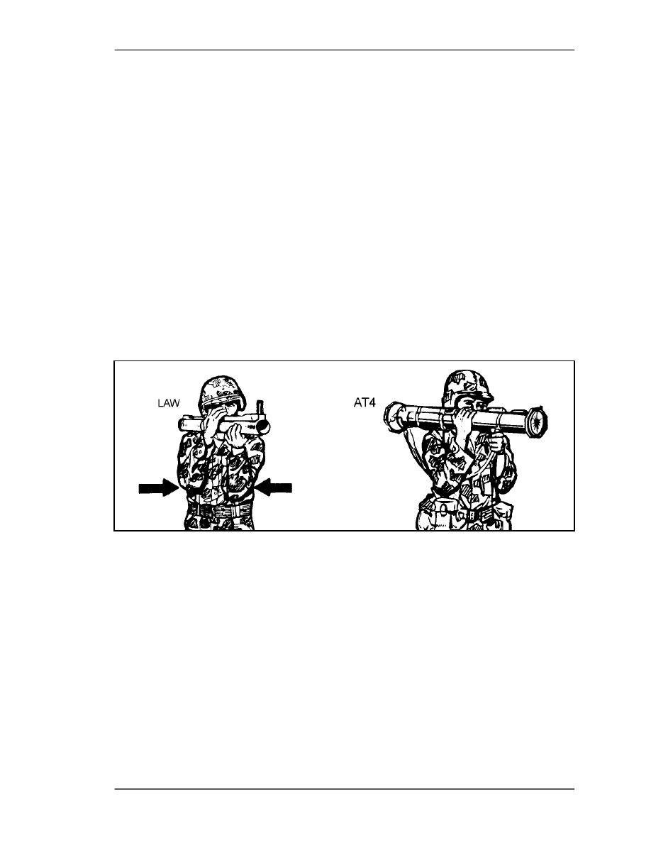
natural extension of his body (Figure 4-1). With both weapons, keep your elbows close to
your body to help balance the weapon and prevent you from jerking or flinching when
you fire. In the case of the AT4, this reduces recoil.
Figure 4-1. Steady hold position.
a. M72-Series LAW. Place your left hand, palm facing upward, under the launcher
near the muzzle and grasp the launcher. Firmly pull the rear cover into your right
shoulder pocket.
b. M136 AT4. With your left hand, grasp the carrying sling where it attaches to the
launcher near the muzzle. With your right hand on the trigger mechanism, pull the
shoulder stop into your right shoulder pocket.
4-2.
AIMING PROCEDURES
Aiming procedures include placing the eye correctly, obtaining a sight picture, and
aligning the sight. Combining these procedures is critical to correctly aiming light
antiarmor weapons.
FM 3-23.25
4-2
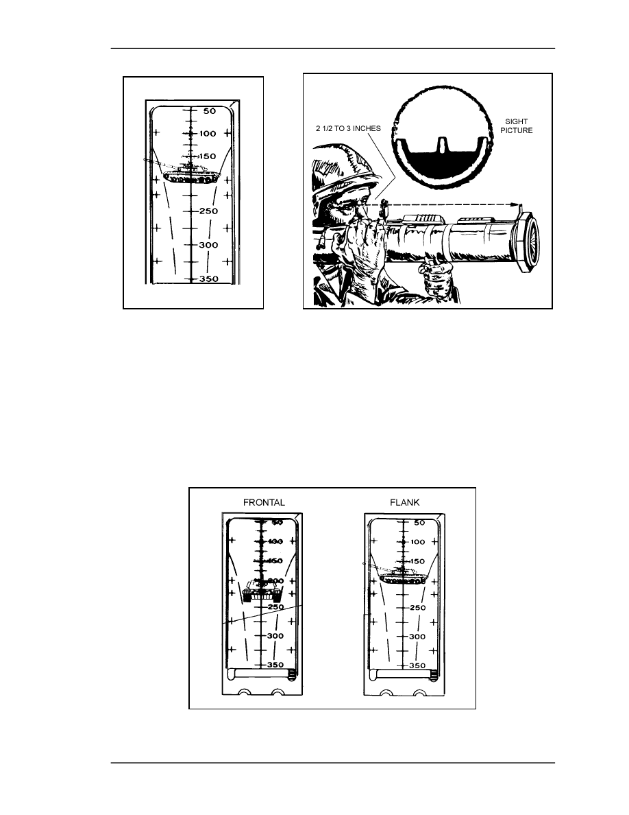
a. Eye Placement. Before sighting the weapon, estimate the range (Chapter 6
discusses range estimation). For the M72-series LAW, place your firing eye as close to
the rear sight as is comfortable. However, for the M136 AT4, place your firing eye
between 2 1/2 to 3 inches (no nearer than 2 1/2 inches) from the rear sight. This distance
is necessary to prevent possible injury from the weapon's recoil and for correct sight
alignment with the AT4 (Figure 4-2).
Figure 4-2. Eye placement.
b. Sight Alignment. Align the sights correctly with the target. To do this for the
M72-series LAW, position the rear sight so that your eye is near and in line with the
peephole in the rear sight. Look through the peephole at the front sight reticle and place
the range line that corresponds to the target's range on the target (Figure 4-3). To do this
for the AT4, position the rear sight so that the white semicircle of the front sight is a hazy
line around the bottom half of the rear sight opening. Position the front sight posts on the
target (Figure 4-4). Align the sight by moving your head forward or backward.
WARNING
When firing the M136 AT4, do not place your eye
within 2 1/2 inches of the rear sight. The AT4s recoil
could cause the rear sight to injure your firing eye.
FM 3-23.25
4-3
Figure 4-3. Sight alignment Figure 4-4. Sight alignment
for the M72-series LAW. for the M136 AT4.
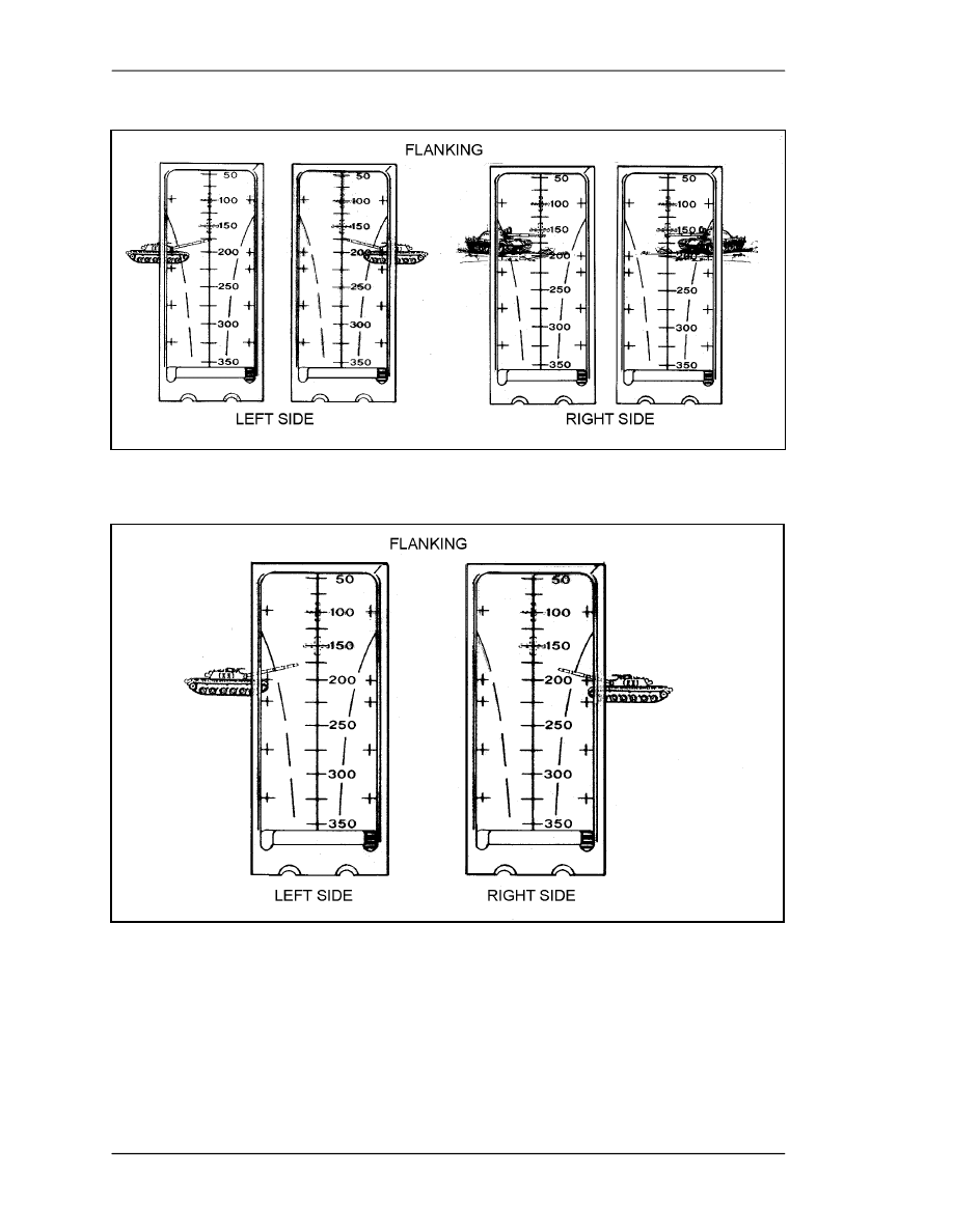
c. Sight Picture. Position the front sight on the target.
(1) M72-Series LAW. Stationary targets include those moving directly toward or
away from the firer. Place the correct vertical range line in the center of the target
(Figure 4-5). Slow-moving targets include those with an estimated speed of 5 mph or
slower, or those moving in an oblique direction. Place either the left or right lead cross
mark on the vehicle's center of mass (Figure 4-6). Fast-moving targets include those with
an estimated speed of more than 5 mph. Place either the left or right lead cross mark on
the leading edge of the vehicle (Figure 4-7).
Figure 4-5. Sight picture, stationary targets, M72-series LAW.
FM 3-23.25
4-4
Figure 4-6. Sight picture, slow-moving targets, M72-series LAW.
Figure 4-7. Sight picture, fast-moving targets, M72-series LAW.
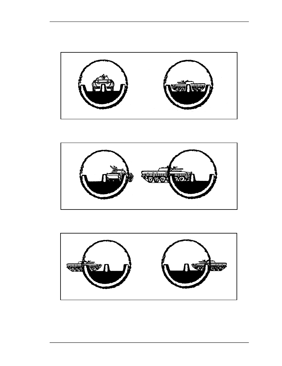
(2) M136 AT4. Stationary targets include those moving directly toward or away from
the firer. Adjust the rear sight for the correct range and place the center sight post in the
center of the target (Figure 4-8). Slow-moving vehicles are those with an estimated speed
of 10 mph or less, or those moving in an oblique direction. Place the center sight post on
the front or leading edge of the vehicle (Figure 4-9). Fast-moving vehicles are those
estimated to be moving faster than 10 mph. Place either the left or right lead post on the
FM 3-23.25
4-5
center of the target. For example, if the target is moving from left to right, place the left
lead post on the target's center of mass, and vice versa (Figure 4-10).
Figure 4-8. Sight picture, stationary targets, M136 AT4.
Figure 4-9. Sight picture, slow-moving targets, M136 AT4.
Figure 4-10. Sight picture, fast-moving targets, M136 AT4.
FM 3-23.25
4-6
4-3.
BREATH CONTROL
Breath control is as important when firing a light antiarmor weapon as it is when firing an
individual weapon. Breathing while firing can cause a miss. To control breathing, the
firer breathes deeply a couple of times, takes one last deep breath, exhales partly, holds
his breath, sights, and fires.
4-4.
TRIGGER MANIPULATION
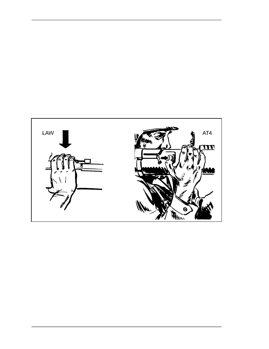
Light antiarmor weapons have different types of triggers (Figure 4-11).
a. LAW. To fire the LAW, the firer must apply firm and steady downward pressure
to the trigger with the fingers of his firing hand.
b. AT4. To fire the AT4, the firer must apply firm and steady forward pressure to
the trigger with the thumb of his firing hand. Soldiers can practice trigger manipulation
and control techniques on an expended launcher or FHT.
Figure 4-11. Trigger manipulation.
4-5.
INTEGRATED ACT OF SHOOTING
Correct sight alignment is critical. Sight alignment errors increase as the range to the
target increases. Therefore, maintaining the correct relationship between the rear and
front sights is as important as placing the aiming point. The steps for doing this should
become automatic. No matter how quickly they are done, these steps are always distinct,
because the human eye can only focus at one distance and on one point at a time. The
firer focuses on the front sight to obtain correct sight alignment, then places the aiming
point to complete the sight picture. He shifts or adjusts the position of the launcher as
necessary. The whole time he is pressing the trigger, he maintains the sight picture.

FM 3-23.25
5-1
CHAPTER 5
FIRING POSITIONS
This chapter explains the basic firing positions used with light
antiarmor weapons. Instructions for each are given for right-handed
firers, but the M72-series LAW can be fired from either shoulder by simply
reversing the instructions. Though each weapon can be fired from all four
of the basic firing positions, individual physique determines exact body
and hand positions. Firing from a supported position naturally increases
accuracy, which improves the odds for a first-round hit or kill. Basic
safety considerations are the same for all light antiarmor weapons, but
additional considerations for each firing position are provided here.
5-1.
STANDING POSITION
Two standing positions are used: a basic standing position and one modified for the
infantry fighting position.
a. Basic Standing Position. Raise the launcher slightly higher than shoulder level.
Execute a left face, rotate your shoulder under the launcher, and spread your feet a
comfortable distance apart. Move your left foot 15 to 24 inches forward, keeping your
hips level and your weight balanced on both feet. To obtain a firm, stable position, tuck
both elbows tightly into your body. To track a moving target, turn your body at the
waist―not with your legs. This enables you to track the target smoothly. Unless you are
behind a protective barrier such as a wall, the standing position exposes you more than
any other position to enemy observation and possible suppression. Differences between
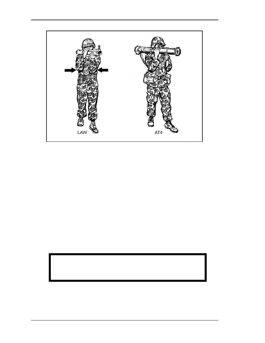
weapons with respect to the standing position are as follows (Figure 5-1, page 5-2):
(1) M72-Series LAW. Place your nonfiring hand about 4 inches from the front of the
muzzle, with your firing hand on the rear cover. After placing the weapon on your
shoulder, release the rear cover and place your firing hand on the trigger. Cup the
launcher in the palm of your nonfiring hand. Position your firing eye as close to the rear
sight as is comfortable.
(2) M136 AT4. Grasp the sling near the launcher with your left hand and the shoulder
stop with your right hand. Raise the launcher above shoulder level. After placing the
launcher on your shoulder, release the shoulder stop and place your right hand on the
trigger. Place your firing eye 2 1/2 to 3 inches from the rear sight.
WARNING
Always keep the launcher pointed in the direction of fire.
FM 3-23.25
5-2
Figure 5-1. Basic standing position.
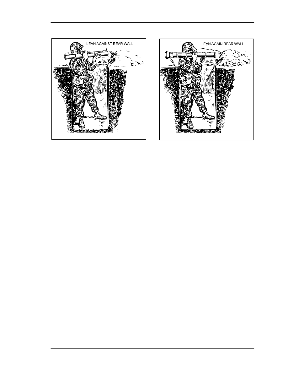
b. Modified Standing Position. Use this position when you occupy an infantry
fighting position. Assume the basic standing position, but instead of stepping forward,
lean against the back wall of the fighting position. Ensure that the venturi or rear of the
weapon extends beyond the rear of the fighting position. Figure 5-2 shows the modified
standing position for the M72-series LAW; Figure 5-3 shows the modified standing
position for the M136 AT4. Ensure that NONE of the following are in your backblast
area:
•
Other soldiers.
•
Other fighting positions.
•
Equipment.
•
Any part of your own fighting position.
•
Obstructions within 5 meters.
NOTE:
Leaders must ensure that light antiarmor weapons are positioned so that the
backblast misses other fighting positions.
DANGER
NEVER FIRE FROM WITHIN A COMPLETELY ENCLOSED,
UNVENTILATED BUNKER OR FIGHTING POSITION.
FM 3-23.25
5-3
Figure 5-2. Modified standing, Figure 5-3. Modified standing
position, M72-series LAW. position, M136 AT4.
5-2.
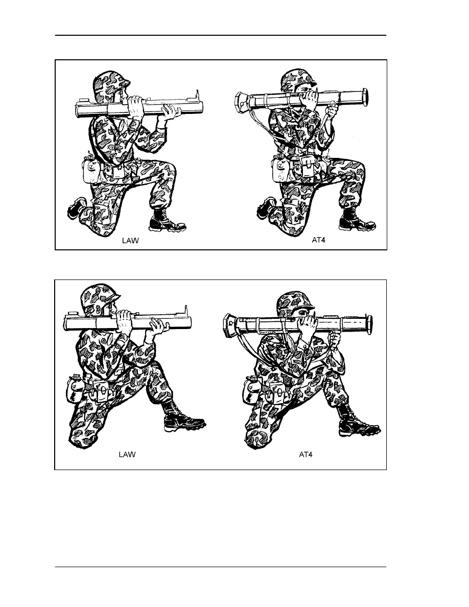
KNEELING POSITION
The basic kneeling position is the best position for tracking moving targets. The modified
kneeling position is best for engaging stationary targets, since it is a supported position.
However, either can be used for stationary or moving targets.
a. Basic Kneeling Position. Kneel from the basic standing position onto your right
knee, keeping your left thigh parallel to the ground. Rotate your lower right leg
90 degrees to the left. (This removes your right foot from exposure to the backblast.)
Keep your right thigh and back straight and perpendicular to the ground. Point your left
foot in the direction of fire and tuck your elbows in to your sides. Though this is not a
supported position, it should be a firm, stable one. Figure 5-4 shows the basic kneeling
positions for the LAW and AT4.
b. Modified Kneeling Position. From the basic kneeling position, sit back on your
right heel. Place the back of your upper left arm on your left knee, making sure you do
not have bone-to-bone contact between your left elbow and left knee. Keep your right
elbow tucked in close to your right side. Use any protective barriers available. Figure 5-5
shows the modified kneeling positions for the LAW and AT4.
FM 3-23.25
5-4
Figure 5-4. Basic kneeling positions.
Figure 5-5. Modified kneeling positions.
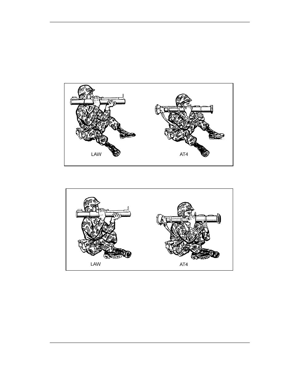
5-3.
SITTING POSITION
The sitting position is the most stable firing position. In this position, the arms are placed
on the legs for support. Depending on his physique, the firer can use either of two
versions of the sitting position. Either is suitable for engaging stationary targets.
FM 3-23.25
5-5
a. Basic Sitting Position. Sit on your buttocks while facing the target, and spread
your feet a comfortable distance apart. Lean forward and place the backs of your upper
arms on your knees, avoiding bone-to-bone contact. Figure 5-6 shows the basic sitting
positions for the LAW and AT4.
b. Modified Sitting Position. From the basic sitting position, cross your ankles for
added support. Raise or lower your knees to adjust for elevation on the target. Figure 5-7
shows the modified sitting positions for the LAW and AT4.
Figure 5-6. Basic sitting positions.
Figure 5-7. Modified sitting positions.
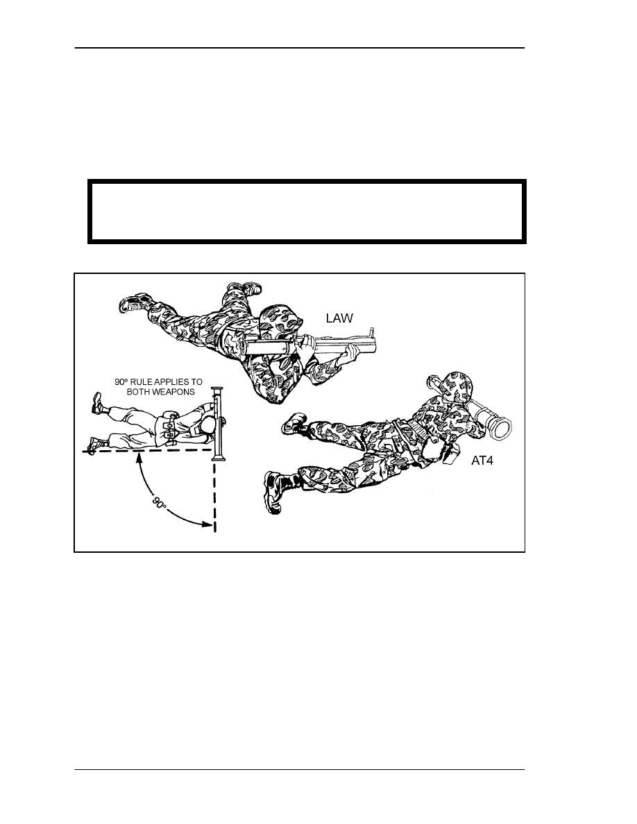
5-4.
PRONE POSITION
The prone position is the most dangerous position due to its proximity to the ground.
Ideally, the ground should slope downward from the rear of the launcher. This slope
reduces the effects of the backblast.
a. Lie on your stomach with your body at a 90-degree angle to direction of fire, and
with your body and legs to the left of the direction of fire.
FM 3-23.25
5-6
b. Ensure that neither the body nor the legs are in the backblast area.
c. Unlike other firing positions, this one prevents you from placing the launcher on
your right shoulder. Instead, you must hold the launcher in place against your upper right
arm. For stability, apply extra pressure on the firing mechanism with your right hand. The
prone position is the least stable of all firing positions. You must practice it often to
become confident using it. Figure 5-8 shows the prone positions for the LAW and AT4.
Figure 5-8. Prone positions.
DANGER
FAILURE TO MAINTAIN A 90-DEGREE ANGLE FROM THE DIRECTION
OF FIRE COULD CAUSE INJURY OR DEATH TO THE FIRER.

FM 3-23.25
6-1
CHAPTER 6
COMBAT TECHNIQUES
This chapter discusses employment techniques for light antiarmor
weapons, all of which require at least basic gunnery skills. Techniques
that require advanced skills are identified as such.
6-1.
RANGE ESTIMATION
A firer who can accurately estimate the range to the target has a better chance of hitting
it, regardless of the weapon used. Common methods of estimating range are listed below
from the most to the least accurate. The tactical situation determines the method to be
used:
a. Using range finders.
b. Measuring the distance on a map after correctly plotting your own position.
c. Pacing. Remember your individual pace count.
d. Using pair and sequence methods of target engagement. This method should be
used only when in contact with the enemy.
e. Estimating range visually. This is the least accurate method of estimating range
and therefore the least desirable. However, in an offensive operation or hasty defense, it
may be the only method available to the light antiarmor firer. Thus, soldiers must
continually train to improve their skill at visual estimation (STP 21-1-SMCT). Leaders
should identify, coordinate, and record ranges to possible armored vehicle engagement
locations on squad and platoon sector sketches.
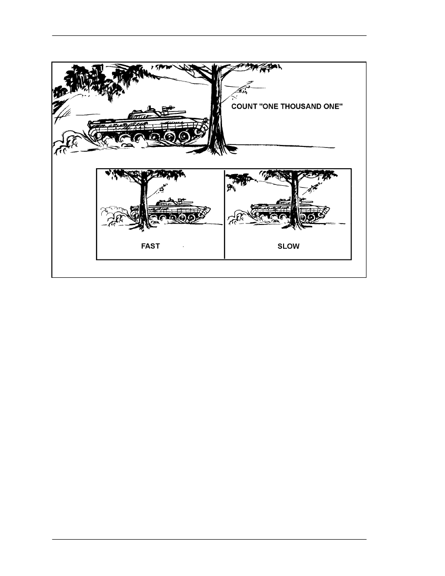
6-2.
SPEED ESTIMATION
Of the weapons discussed in this manual, the M136 AT4 is the best for engaging moving
armored vehicles. One of its advantages over the LAW is the speed of its round, which
travels faster and farther than the LAW round. However, the firer is the key in any
engagement, especially a moving target engagement. Once soldiers learn to estimate
speeds at known ranges, they should rehearse until they achieve a high hit-to-kill ratio.
As their abilities improve, the leaders vary the ranges, speeds, and types of armored
vehicles (Figure 6-1, page 6-2). Trainers and soldiers develop other methods through
practice and are limited only by their imaginations. (Chapter 4 discusses obtaining a sight
picture in detail.) Estimate how far the vehicle travels in 1 second:
a. Start when the front end of the vehicle passes the object.
b. Count, “One thousand and one” (takes about one second).
c. If more than half of the vehicle passes the object, estimate it as a fast-moving
vehicle (10 mph or faster). If less than half of the vehicle passes the object, estimate it as
a slow-moving vehicle (less than 10 mph).
FM 3-23.25
6-2
Figure 6-1. Speed estimation.
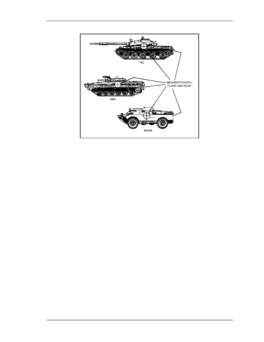
6-3.
ARMORED VEHICLE WEAKNESSES
Armored vehicles usually have their heaviest armor in front, because they are designed
mainly for offensive operations against other armored vehicles (Figure 6-2). All vehicles
are vulnerable to repeated hits on their flanks and rear, though the flank offers the largest
possible target. Firers should always aim center of mass to increase the probability of a
hit. The older the vehicle model, the less protection it has against antiarmor weapons.
Consequently, newer versions may use bolt-on (applique) armor to improve their
survivability. Some vehicles are equipped with reactive armor, which consists of metal
plates and plastic explosives. Reactive armor usually covers the forward-facing portions
and sides of the vehicle and can defeat shaped-charge weapons such as the LAW and
AT4. When reactive armor detonates, it disperses metal fragments to 200 meters. The
M72-series LAW and the M136 AT4 cause only a small entry hole in an armored vehicle
target, though some fragmentation or spall may occur.
FM 3-23.25
6-3
Figure 6-2. Armored vehicle weak points.
a. Natural or man-made obstacles can be used to force the armored vehicle to slow,
stop, or change direction. This pause enables the firer to achieve a first-round hit. If he
does not achieve a catastrophic kill on the first round, he or another firer must be ready to
engage the target vehicle immediately with another round.
b. An armored vehicle without close protection (dismounted infantry) in woods,
MOUT, or other restrictive terrain is vulnerable to close attack. This type of attack is
most likely to originate from well-armed infantry-type teams organized into armor-killer
teams. (Noninfantry units may also be required to perform this mission.) Skilled firers
from these teams should engage the suspension or engine compartment of vehicles that
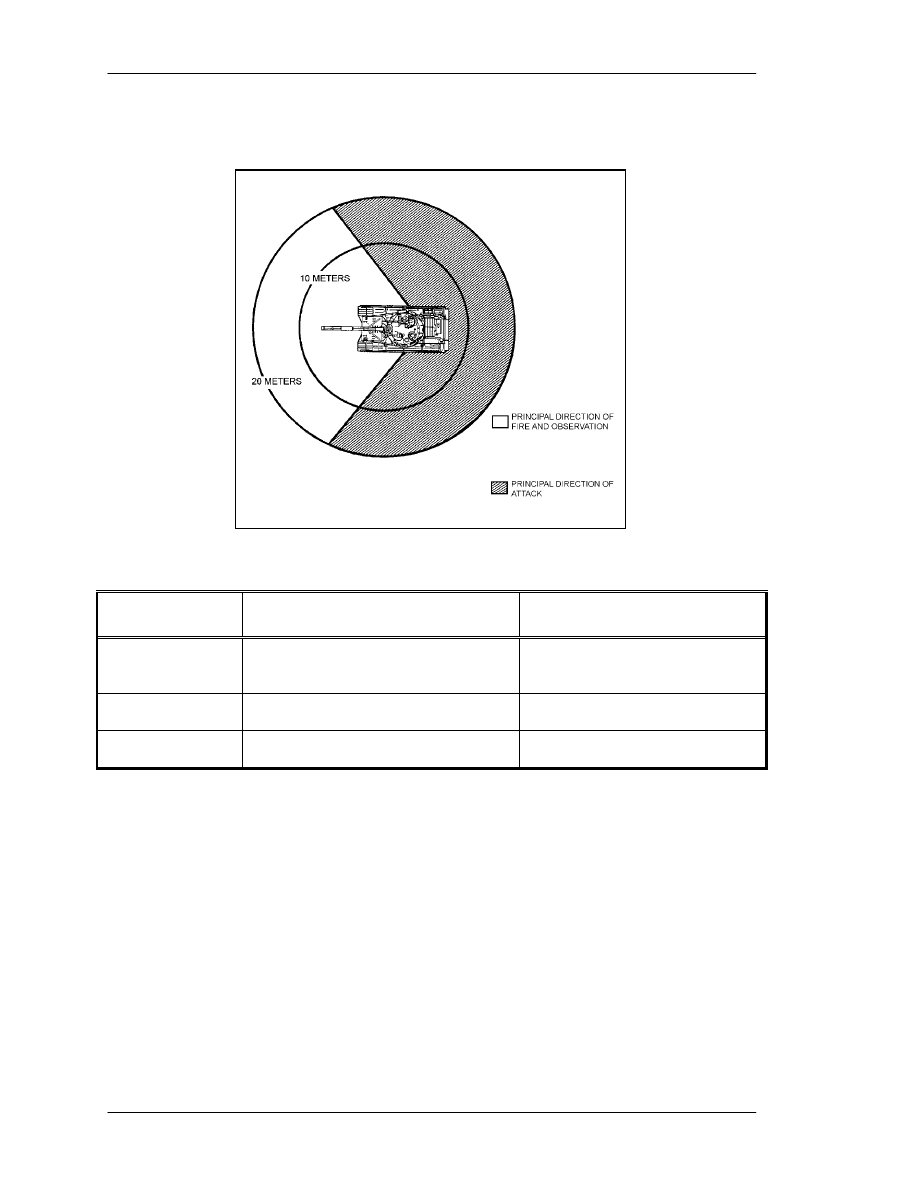
have applique or reactive armor. When an armored vehicle is buttoned up
all hatches
are closed and personnel are inside the vehicle
the crew cannot see well enough to
protect itself from close attacks or attacks from the flanks or rear. The personnel inside
cannot see anything within 10 meters of the vehicle, and they cannot shoot at anything
(using their main guns) within 20 meters. The white area in Figure 6-3, page 6-4 shows
the most favorable direction of attack when the turret is facing to the front; the gray area
shows the vehicle's principal direction of fire and observation when the turret is facing to
the front.
FM 3-23.25
6-4
c. Armored vehicle kills are classified according to the level of damage achieved
(Table 6-1).
Figure 6-3. Limited visibility of armored vehicles.
TYPE OF KILL
PART OF VEHICLE
DAMAGED OR DESTROYED
CAPABILITY AFTER KILL
Mobility Kill
Suspension (track, wheels, or road
wheels) or power train (engine or
transmission) has been damaged.
Vehicle cannot move, but it can
still return fire.
Firepower Kill
Main armament has been disabled.
Vehicle can still move, so it can
get away.
Catastrophic Kill
Ammunition or fuel storage section
has been hit by more than one round.
Vehicle completely destroyed.
Table 6-1. Armored vehicle kills.
6-4.
METHODS OF ENGAGEMENT
The four engagement methods include single, sequence, pair, and volley firing. The
leader evaluates the situation on the ground to determine which of these methods to use.
Regardless of whether they are used singly or in combination, communications are
needed as well. The methods of engagement are rehearsed IAW unit SOP.
a. Single Firing. A single soldier with one light antiarmor weapon may engage an
armored vehicle, but this is not the preferred method of engagement. Several light
antiarmor weapons are required to kill an armored vehicle. A single firer firing one round
must hit a vital part of the target to damage it at all (Figure 6-4).
FM 3-23.25
6-5
(1) Range Not Known. A single firer should engage only targets within 200 meters
when he does not know the actual range. The probability that he hits a target beyond
200 meters with a single round is small.
(2) Range Known. A single firer can engage targets out to 225 meters with the LAW
or 300 meters with the AT4 when he knows the actual range. The firer should do this only
when he has a flank or rear shot, or when he has no other engagement option.
Figure 6-4. Single firing.
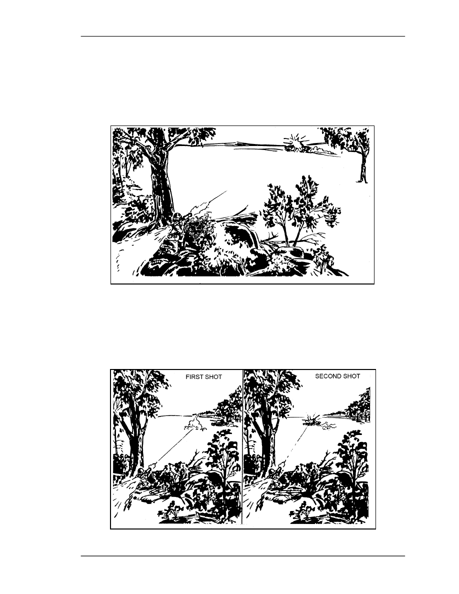
b. Sequence Firing. A single firer, equipped with two or more light antiarmor
weapons prepared for firing, engages the target. After engaging with the first round and
observing the impact, the firer adjusts his point of aim, engages with another round, and
so on until he destroys the target or runs out of rounds (Figure 6-5).
FM 3-23.25
6-6
Figure 6-5. Sequence firing.
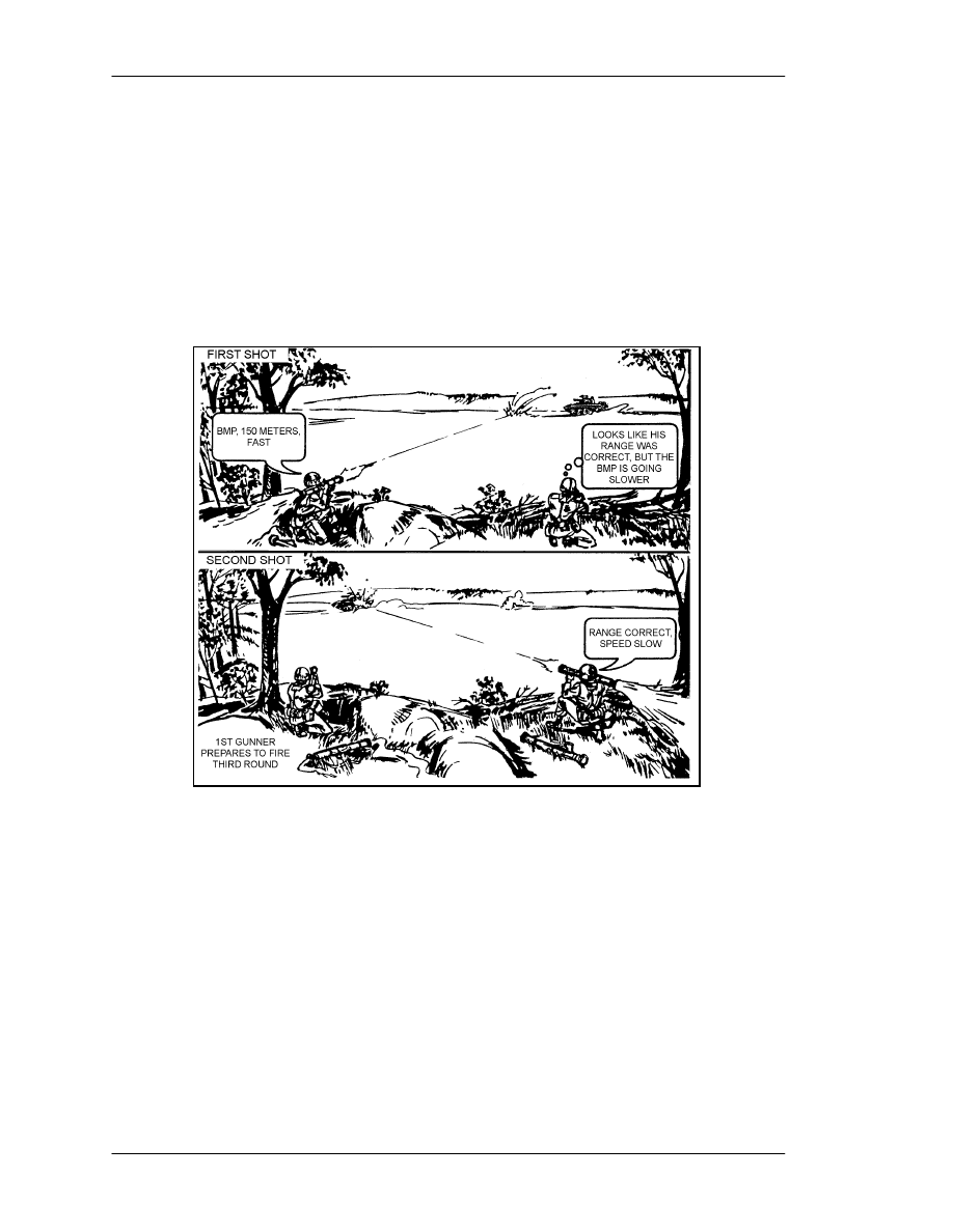
c. Pair Firing. Two or more firers, equipped with two or more light antiarmor
weapons prepared for firing, engage a single target. Before firing, the first firer informs
the others of the estimated speed and distance to the target. If the impact of his round
proves his estimate to be correct, the other firers engage the target until it is destroyed. If
the impact of the round proves his estimate to be incorrect, the second firer informs the
others of his own estimate, then he engages the target. This continues until the target is
destroyed or all rounds are expended (Figure 6-6).
Figure 6-6. Pair firing.
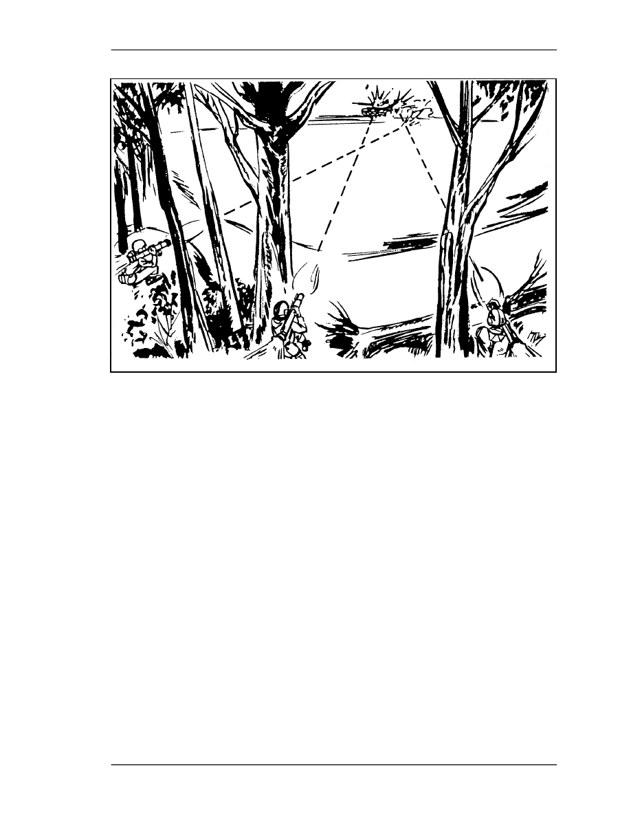
d. Volley Firing. Two or more firers can engage a single target when the range is
known. These firers engage the target at one time on a prearranged signal such as a
command, whistle, booby trap, mine, or TRP. For the best method of engagement, use the
light antiarmor weapon, because it places the most possible rounds on one target at one
time, increasing the possibility of a kill (Figure 6-7).
FM 3-23.25
6-7
Figure 6-7. Volley firing.
e. Communications. Leaders control all unit fire and communicate this information
to the entire unit IAW unit SOP. Light antiarmor weapons firers must know
•
Designated firers.
•
Target priority.
•
Method of engagement.
•
Range and lead to target (if known).
•
Command or signal to fire.
•
Command or signal to cease fire.
6-5.
ENGAGEMENT OF FIELD FORTIFICATIONS AND BUILDINGS
Light antiarmor weapons have little effect against field fortifications and buildings.
Soldiers should not expect to severely damage targets with these weapons. However, if
the alternatives shown in Table 6-2, page 6-8, are used, soldiers may be able to gain a
temporary advantage.
6-6.
ENGAGEMENT OF OTHER VEHICLES
The M72-series LAW proves more effective against light vehicles; the M136 AT4 proves
more effective against armored vehicles. Nonarmored vehicles, such as trucks, cars, and
boats, are considered soft targets. Firing along their length offers the greatest chance of a
kill, because this type of shot is most likely to hit their engine block or fuel tank.

FM 3-23.25
6-8
AIM
POINT
EFFECT WHEN WEAPON
IS FIRED AT AIM POINT
RECOMMENDED
FIRING TECHNIQUE
BUNKER OR FIGHTING POSITION
Firing
Port or
Aperture
Rounds fired into firing ports or apertures
are wasted: rounds detonate inside rear of
position, causing little structural damage to
the position or to the equipment or
personnel within, unless they are hit
directly. The AT4 produces less effect than
the LAW.
Coordinate fire: Fire light antiarmor
weapons at a point 6 to 12 inches
from the front edge of the firing
ports in the berm. Fire small arms
at the bunker or position to prevent
personnel within from returning
light antiarmor fire.
Berm
Firing at the berm causes the round to
detonate outside the fighting position or
inside the berm, creating only a small hole
in the berm, dust, or minor structural
damage to the position, but no damage to
personnel or equipment unless they are hit
directly. The AT4 produces less effect than
the LAW.
Window
The round may travel completely through
the structure before detonating; if not, it
creates dust and causes minor structural
damage to the rear wall, but little damage
to personnel or equipment, unless they are
hit directly. The AT4 produces less effect
than the LAW.
Fire 6 to 12 inches from the sides
or bottom of a window. Light
antiarmor rounds explode on
contact with brick or concrete,
creating an opening whose size is
determined by the type of round
used.
Wall
The round detonates on contact, creating
dust and causing a small hole and minor
structural damage, but little damage to
personnel or equipment, unless they are hit
directly. The LAW may be used to create a
loophole, which is a hole large enough to
throw hand grenades through. The AT4
produces less effect than the LAW.
Corner
Corners are reinforced and thus harder to
penetrate than other parts of a wall. Any
light antiarmor round will detonate sooner
on a corner than on a less dense surface.
Detonation should occur in the targeted
room, creating dust and causing
overpressure, which can temporarily
incapacitate personnel inside the structure
near the point of detonation. The AT4
causes more overpressure than the LAW.
Table 6-2. Effects of light antiarmor weapons
on field fortifications or bunkers.

FM 3-23.25
6-9
6-7.
LIMITED VISIBILITY ENGAGEMENTS
Limited visibility engagements can be conducted using various night vision devices or
with artificial illumination. However, when NVDs or artificial illumination is used,
limited visibility can reduce the maximum effective range for light antiarmor weapons by
at least one-third. To avoid fratricide, leaders must ensure all designated light antiarmor
weapon firers are trained to use their weapons in limited visibility.
a. Night Vision Device
.
Before a NVD can be used with the M136/AT4, it must be
removed from its designated weapon (M249 machine gun or automatic weapon, or M60
machine gun) and the M136/AT4 mounting bracket must be attached. Appendix F
describes the various NVDs that can be used, it also gives information for mounting,
boresighting, and zeroing procedures for each NVD.
b. Artificial Illumination. If artificial illumination is used during a limited visibility
engagement, it should be placed above and slightly beyond the target. However, the
ability to identify and engage targets is even less with artificial illumination than with
NVDs.
6-8.
ENGAGEMENT IN NBC CONDITIONS
Wearing a protective mask limits the firer's ability to sight the weapon. Wearing NBC
gloves limits his ability to manipulate the firing mechanism.
a. Sighting the Weapon. Sighting while wearing the protective mask may require
rotating the weapon slightly counterclockwise. The mask also makes determining the
location, identity, and engageability of targets more difficult.
b. Firing the Weapon. Practice manipulating the firing mechanism while wearing
NBC gloves.
NOTE:
When live firing either a light antiarmor weapon or its subcaliber trainer, aim
within range firing limits.
6-9.
ENGAGEMENT FROM AN ENCLOSURE
Firing from an enclosure creates unique hazards. As such, before positioning soldiers in
enclosures (in combat only), leaders must consider several factors that affect safety. Only
in combat, when no other tactical option exists, should the M136 AT4 be fired from an
enclosure. If it must be employed this way, the enclosure must meet the following
minimum requirements. The M72-series LAW has been rated as safe for use from an
enclosure but, again, only when the enclosure meets the following minimum
requirements:
DANGER
THE M136 AT4 IS NOT RATED SAFE. IN TRAINING,
NEVER FIRE IT FROM AN ENCLOSURE; IN COMBAT, DO
SO ONLY WHEN NO OTHER POSITION IS AVAILABLE.
THE OVERPRESSURE AND BLAST COMBINED CREATE
CONDITIONS THAT CAN KILL YOU. IF THEY DON'T KILL
YOU, THEY CAN INJURE YOU SERIOUSLY OR DEAFEN
YOU TEMPORARILY OR PERMANENTLY

FM 3-23.25
6-10
a. Construction. The building must be sturdily constructed to reduce the structural
damage that would occur in a weakly constructed enclosure such as one made of wood or
stucco.
b. Size of Enclosure. Minimum measurements for the enclosure are as follows:
•
AT4
minimum room size 17 x 24 feet.
•
LAW
minimum room size 12 x 15 feet.
•
Both
minimum ceiling height 8 feet.
c. Ventilation to the Rear and Sides. To allow for the backblast, at least
20 square feet of ventilation
such as a standard 3-foot by 7-foot doorway
must be
provided directly behind the firer. More doors and windows are removed beside and
behind the position to increase ventilation and reduce overpressure, noise, and blast
effects. Without sufficient ventilation, the blast would weaken or collapse the walls. On
the front wall, windows and doors are reinforced rather than removed, because removing
would draw attention to the position. Reinforcing the windows also helps protect the firer
from enemy direct-fire weapons.
d. Objects and Debris. All objects and debris are removed from the rear of the
weapon, because the backblast causes them to fly around the room injuring personnel.
e. Muzzle Clearance. Muzzle Clearance must be at least 6 inches.
f. Weapon Clearance. Properly positioning the weapons within the enclosure is
vital to the safety and survival of all personnel in the enclosure. The weapons should be
positioned so that no walls are within 5 meters to the rear or side of the weapon.
g. Personnel Positions. If any other soldiers must be present, then they must remain
forward of the rear of the launcher and avoid standing in corners or near walls. If
possible, they should construct reinforced positions that fit the previous criteria and that
can protect them in case the building collapses.
6-10.
ENGAGEMENT BEYOND MAXIMUM EFFECTIVE RANGE
(M136 AT4 ONLY)
A skilled M136 AT4 firer can engage targets beyond the weapon's maximum effective
range of 300 meters, up to 550 meters. Beyond 550 meters, the firer must aim higher than
center of mass and apply additional lead for moving targets. Commanders must realize
that accuracy is reduced at these ranges. Also, firing at these ranges identifies the firing
position to the enemy.
6-11. OFFENSIVE OPERATIONS
All elements, even those with other organic antiarmor weapons, use light antiarmor
weapons. Light antiarmor weapons can influence the action in an attack, so units should
routinely stock them beforehand. They are most useful against lightly armored vehicles.
They can also be used against soft targets, such as bunkers, field fortifications,
automobiles, and trucks, but their shaped-charge warheads have less effect on these than
WARNING
To avoid injuring the eardrums, soldiers must wear the
approved brand of ear protection.
FM 3-23.25
6-11
on armored targets. Unless personnel, ordnance, or flammable material on or inside them
are hit, soft targets can normally continue to fight after being attacked by light antiarmor
weapons. Due to their relatively short range, light antiarmor weapons should be placed
throughout the attacking force. They support the maneuver by providing a base of fire,
and they enable the assaulting force to engage in close antiarmor combat.
6-12. DEFENSIVE OPERATIONS
Whether or not other organic antiarmor weapons are available, light antiarmor weapons
are an asset in the squad and platoon defensive plan.
a. Light antiarmor weapons are employed with interlocking fires to provide mutual
support. Dispersion allows leaders the flexibility to place flank, rear, and oblique fires on
targets. This procedure increases the survivability of the firers as well as the probability
of achieving kills. Leaders must select positions that avoid fratricide from antiarmor
backblast and short rounds (Appendix A).
b. The squad and platoon leader's sector sketch identifies TRPs and primary areas of
possible engagement. The sector sketch also identifies possible avenues of approach for
enemy armored vehicles. Each light antiarmor weapon shares a sector of fire with the
primary small-arms weapon assigned to its position. However, because it is neither a
primary nor crew-served weapon, the light antiarmor weapon does not require a separate
range card. When assigning sectors of fire, squad and platoon leaders inform firers of all
possible target areas, TRPs, and prearranged signals (Figure 6-8). (FMs 7-7, 7-7J, and 7-8
provide more information about the squad and platoon sector sketch.) Leaders provide
each designated position with two or more light antiarmor weapons.
Figure 6-8. Squad sector sketch.
6-13. OTHER TACTICAL OPERATIONS
The weight of the light antiarmor weapon suits it well for combat patrols and rear area
operations. (FM 7-8 provides more information about these subjects.)
FM 3-23.25
6-12
a. Combat Patrols. Light antiarmor weapons are used on combat patrols to destroy
enemy equipment, installations, and key points, and to harass enemy forces. The two
types of combat patrols are―
(1) Ambushes (Antiarmor). The commander can employ armor-killer teams
either during limited visibility or when cover, concealment, and withdrawal routes are
available. The key to ambushing armored or other vehicles is to choose terrain that
restricts their maneuverability and fields of fire, but that allows friendly forces to engage
the vehicles from the flank and rear. Soldiers can emplace antipersonnel mines before the
ambush so that dismounting enemy soldiers deploy into them. Though light antiarmor
weapons can be used independently, they are normally used in support of designated
organic antiarmor weapons such as the Dragon. Volley firing light antiarmor weapons
increases the probability of a quick kill (Figure 6-9). Security teams stop the enemy from
escaping.
Figure 6-9. Antiarmor ambushes.
(2) Raids. Using light antiarmor weapons on raids increases target options. Light
antiarmor weapons can also be used to defend against armored vehicles.
b. Rear Area Operations. Rear area operations usually consist of either: defending
unit trains and tactical operation centers, or patrolling rear areas.

FM 3-23.25
6-13
(1) Defense of Tactical Operations Center and Unit Trains. The mobility of
modern vehicles makes the TOC and unit trains prime targets. Light antiarmor weapons
are used to engage vehicles threatening the unit during the defense of the TOC. Soldiers
who use light antiarmor weapons in this type of operation normally perform noninfantry-
type roles. Unit leaders designate soldiers to carry light antiarmor weapons and ensure
that these soldiers receive light antiarmor weapons training.
(2) Patrols of Rear Areas. Rear area patrols are security patrols conducted by
designated infantry or MP units. These patrols can react to any threat they encounter in
the rear area. Rear area patrols use the light antiarmor weapon in a hasty point defense at
a roadblock, intersection, or strongpoint.

FM 3-23.25
7-1
CHAPTER 7
TRAIN-THE-TRAINER AND UNIT TRAINING
PROGRAMS
During initial-entry training, soldiers receive only an orientation for
each of the light antiarmor weapons. When they arrive in a unit, soldiers
should train to Skill Level 1 proficiency on all assigned weapons and
equipment. Each unit should have an ongoing unit training program to
allow soldiers to work together to attain and sustain their skills. This
program integrates individual and collective tasks. Operating a unit
training program requires the unit to also maintain a train-the-trainer
program. Both programs are planned and conducted IAW the
commander's METL.
7-1.
TRAINING STRATEGY
Training strategy integrates resources into a year-round program to train the individual
and collective skills needed to perform the wartime mission. Thus, units are trained to
fight and win on the battlefield. The training strategy includes institutional and unit
training.
a. Institutional Training. TRADOC schools conduct institutional training. These
courses train critical individual and leader skills required to succeed in combat. Students
are provided the latest doctrine and taught current technical skills associated with the
light antiarmor weapons available within the Army. Soldiers train at several institutional
schools throughout their career (see the appropriate programs of instruction [POIs])
(Table 7-1).
Initial-Entry Training
Primary Leadership Development Course
Basic Noncommissioned Officer Course
ENLISTED
Advanced Noncommissioned Officer Course
Precommission Training
Officer Basic Course
OFFICERS
Officer Advanced Course
Table 7-1. Institutional training.
b. Unit Training. Unit training consists of sustainment training in individual and
collective skills. Commanders manage their resources (devices, simulators, simulations,
ranges, and ammunition) carefully to best develop individual and leader skills. Through
the use of exercises, (drills, STXs, and qualification tables), the unit develops skills and
integrates individuals into a cohesive crew or squad. Table 7-2 provides a training guide
for building a light antiarmor weapons sustainment training plan (see also Appendixes C
and E).

FM 3-23.25
7-2
7-2.
UNIT TRAINING PROGRAM
Every unit commander, including those commanding CS and CSS units, should develop a
program for light antiarmor training. Some units have more than one type of light
antiarmor weapon that requires sustainment training. The commander considers
preparation and training for both collective and individual tasks. Trainers analyze their
collective tasks and the individual tasks that support them. Individual tasks must be
integrated into collective training and rehearsals. The units should try to train light
antiarmor weapons at the same time and on the same range (Appendix D). Otherwise,
these weapons are trained in alternating quarters of the year.
a. Sustainment Training Requirements. Sustainment training is recommended for
each soldier. Active Component units should conduct sustainment training quarterly and
fire the appropriate qualification tables semiannually, depending on the STRAC TRC
level. Reserve Component units should conduct sustainment training semiannually and
fire the appropriate instructional or qualification tables annually. All units should fire
advanced instructional tables semiannually. When possible, they should conduct live fire
annually IAW the current STRAC manual. (Appendix E provides all the necessary firing
tables.) Commanders should ensure that designated gunners complete unit sustainment
training and live fire tactical light antiarmor weapons sometime during that quarter.
Training requirements are divided into four tracks, A through D, based on ammunition
allocations (Table 7-3). Table 7-4 provides an example training frequency chart. This
example is based on the AT4. The same tasks apply to all light antiarmor weapons, but
procedures and standards may vary. Tactical weapons are allocated IAW the current
standards in training commission (STRAC) manual.
1
Designated soldiers should train as often as needed to maintain
proficiency.
2
Performance evaluations should be administered to designated soldiers
quarterly, if resources allow.
3
Designated soldiers should fire the qualification tables semiannually for
verification on designated weapons.
4
Designated soldiers qualify semiannually on their designated weapons.
Qualification consists of a hands-on performance evaluation and
qualification firing tables.
5
Designated soldiers should be trained in advanced instructional
techniques as often as the unit training program allows. This training
helps to maintain their target engagement skills.
6
All soldiers not designated as light antiarmor weapons gunners should
train on these weapons to the extent allowed by resources.
Table 7-2. Sustainment training plan for light antiarmor weapons.
FM 3-23.25
7-3
TRACK
DETERMINES ANNUAL
AMMUNITION ALLOCATION
FOR:
A
Each Active Component designated firer.
B
Track deleted
C
Each Reserve Component designated firer.
D
Each Reserve Component training division
instructor.
Table 7-3. Training requirements.
TRAINING
OBJECTIVE
TASK
FREQUENCY
APPROXIMATE
TIME
AC
RC
NA
Conduct an orientation safety
briefing (as appropriate).
Q
A
10 min
1
Inspect an M136 AT4 for
serviceability.
Q
A
30 min
2
Prepare an M136 AT4 for
firing.
Q
A
45 min
3
Demonstrate correct M136 AT4
firing positions.
Q
A
45 min
4
Estimate range.
Q
A
60 min
5
Determine the correct M136
AT4 sight picture.
Q
A
30 min
6
Perform M136 AT4 misfire
procedures.
Q
A
45 min
7
Return the M136 AT4 to the
carrying position.
Q
A
45 min
8
Engage targets with an
M136 AT4.
S
B
3 1/2 hr
KEY:
Q = quarterly (every 90 days)
S = semiannually (twice a year)
A = annually (once a year)
B = biennially (every two years)
Table 7-4. Example training frequency chart.
b. Gunnery Training Requirements. All designated soldiers should be trained to
standard IAW the combat techniques in Chapter 6 and the performance evaluations in
Appendix C.
c. Collective Training. Individual tasks must be integrated into collective training
and rehearsals. To accomplish this, commanders analyze the collective tasks from their
unit METL and the individual tasks that support the collective tasks. The commander
determines the collective tasks that must be practiced by analyzing the mission outlines
FM 3-23.25
7-4
in the appropriate mission training plan (MTP). The mission outlines describe the
collective tasks required to execute each ARTEP mission. Leaders determine the
individual tasks that support the collective tasks by referring to the mission task matrix in
the appropriate MTP.
(1) Leaders use the training standards given in the appropriate manual for the
individual tasks. Noninfantry units can use FMs 7-7, 7-7J, 7-8, 7-10, and 7-20 to identify
infantry-type missions. Some of the tasks identified may include engaging armored
vehicles. When planning training, the trainer incorporates the training devices and aids
for light antiarmor weapons into the unit's training. These devices and aids add realism
and allow trainer to properly evaluate the task being conducted. He must also identify
deficiencies and correct them by retraining soldiers to use the selected weapons and their
related training devices correctly.
(2) The MILES Viper is a force-on-force trainer for light antiarmor weapons. MILES
trainers are not gunnery trainers and are not used for sustainment training. They are used
in all force-on-force training. Table 7-5 provides an example MILES training program.
FREQUENCY
(TIMES PER YEAR)
SEQUENCE
ACTIVE
RESERVE
Squad, platoon, or company
FTX or STX
4
1
Battalion FTX
2
0
Battalion ARTEP
2
1
Total MILES training events
per year
8
2
Table 7-5. MILES training program.
7-3.
TRAIN-THE-TRAINER PROGRAM
The success of the unit's light antiarmor training program depends on trainers who are
well-trained, competent, and prepared to train soldiers.
a. Objectives. The train-the-trainer program must teach trainers to do the following:
•
Evaluate the unit’s training weaknesses.
•
Plan training.
•
Set up, operate, and maintain training equipment.
•
Conduct training.
•
Coach firers in gunnery training.
•
Evaluate firers' training weaknesses.
•
Correct firers' training weaknesses.
•
Instill confidence in the firers trained.
•
Maintain training records.
b. Mission-Essential Task List. The commander must carefully examine his unit's
wartime mission and develop a METL. He must then organize the unit's sustainment
training program to support the METL. The light antiarmor sustainment training plan

FM 3-23.25
7-5
consists of quarterly, semiannual, and annual training events. Between these events, the
unit provides additional light antiarmor weapons training. The sustainment plan should
prepare the unit for the next round of weapons gunnery while also supporting the unit
METL.
c. Trainer Assessment. Trainers within a unit are normally team, squad, and section
leaders and platoon sergeants. Before becoming weapons trainers, they must be assessed
carefully and any shortcomings corrected. The commander chooses a method of
assessing the trainers that ensures that their abilities are accurately evaluated. Then, with
the assistance of the platoon leaders and platoon sergeants, the commander performs this
assessment.
d. Command Benefits. Regular and aggressive train-the-trainer programs provide
valuable benefits that gradually spread through the unit. These benefits include a base of
expertise, proficiency, and esprit de corps. Maintaining this base is easier than recreating
it.
e. Training Tasks. Successful trainers know how to operate the training devices for
the light antiarmor weapons assigned to their units. Based on the unit's METL, the
commander designates the appropriate light antiarmor weapon for specified missions.
Appendix C provides the tasks, conditions, and standards for each weapon discussed in
this manual. The trainers must know the appropriate combat techniques for employing
these weapons. They must also perform the following:
•
Conduct an orientation safety briefing.
•
Inspect the weapons for serviceability.
•
Prepare the weapons for firing.
•
Demonstrate the correct firing positions.
•
Estimate range.
•
Determine the correct sight picture.
•
Perform the correct combat and training misfire procedures.
•
Return the weapon to the carrying configuration.
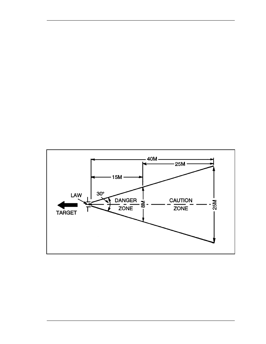
FM 3-23.25
A-1
APPENDIX A
SAFETY
This appendix provides safety procedures for both training and combat.
A-1.
TRAINING SAFETY
Training safety for light antiarmor weapons applies to all types of ranges and training sites.
a. Backblast. Light antiarmor weapons have little or no recoil, because the propellant
gasses escape to the rear of the weapon. This backblast can damage equipment or seriously
injure personnel who are too close to the rear of the launcher. When operating temperatures
fall below freezing (0NC or 32NF), all backblast areas and safety zones double.
(1) M72-series LAW. This is an open-chambered weapon, so it has no recoil. The
launcher's total backblast area extends 40 meters (44 yards) to the rear (Figure A-1) and is
divided into two zones. During training, both should be marked off limits:
(a) Danger zone. All personnel, equipment, and flammable material must be clear of this
area.
(b) Caution zone. The weapon's backblast may throw loose objects to the rear.
Therefore, personnel must also stay clear of this area.
Figure A-1. M72-series LAW backblast area.
(2) M136 AT4. Because the AT4 has a closed chamber, it has a slight recoil. When the
weapon is fired, pressure builds up in the chamber and ruptures the baseplate. Once the
baseplate ruptures, gasses exit from the back of the weapon, forming the backblast. The total
backblast area extends 100 meters to the rear of the launcher in a 90-degree fan (Figure A-2,
page A-2). During training, the entire backblast area should be marked off limits and kept
clear of personnel and equipment. In combat, personnel may remain to the rear of the
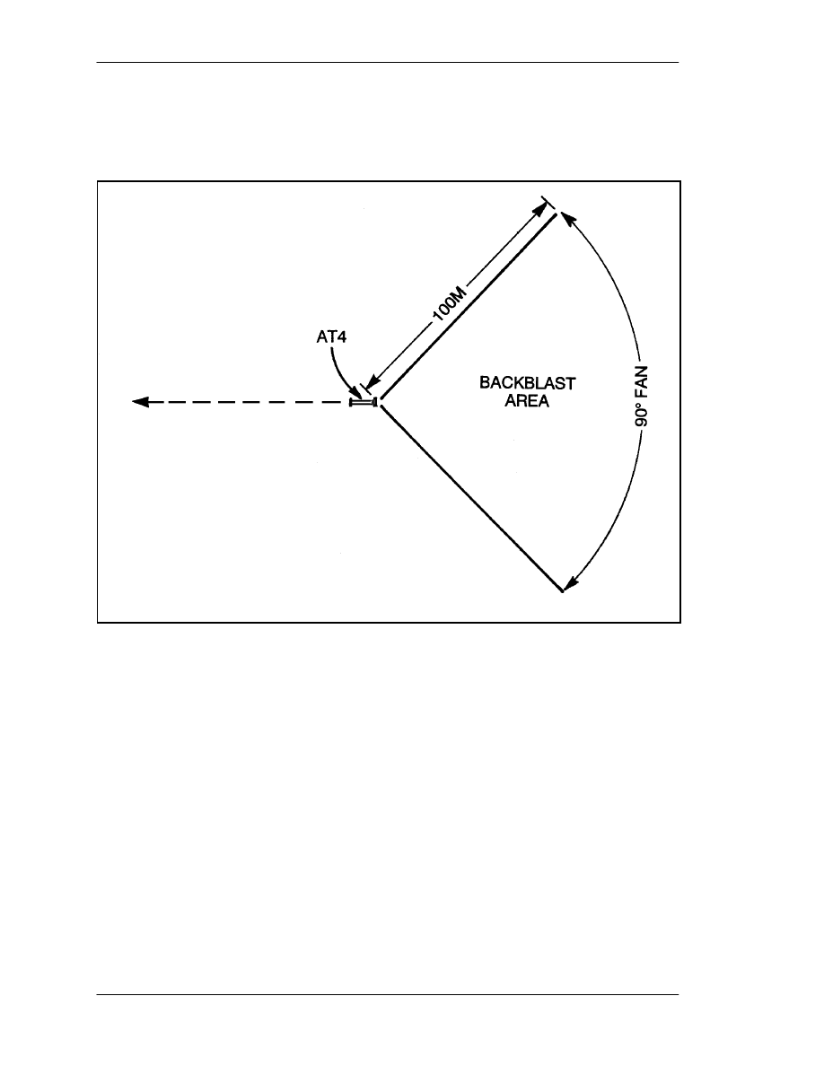
FM 3-23.25
A-2
weapon, but only if they are in protected positions. Backblast heat or flying debris could
injure the firer and other soldiers anywhere in the backblast area. This weapon must not be
fired from an enclosure or in front of a barrier (TM 9-1315-886-12). It may be fired from an
enclosure in combat only when no other tactical option exists.
Figure A-2. M136 AT4 backblast area.
b. Firing Limitations. Trainers and soldiers must observe the backblast danger zones
as well as other firing limitations. A light antiarmor weapon can be fired from the standard
infantry fighting position. However, if this position is chosen, trainers/soldiers must consider
other factors that increase the accuracy and reduce the danger to friendly soldiers: Rear of
launcher extends beyond the back wall of the position, no overhead cover extends into the
backblast area, and at least 1/2 meter (18 inches) clearance is around the weapon.
c. Range Procedures for Light Antiarmor Weapons. For all the light antiarmor
weapons discussed in this manual, these procedures must be followed:
(1) The whole backblast area must be well marked and must be clear of all personnel,
equipment, and flammable materials.
(2) No one enters the area behind the firing line or forward of the rear safety line without
permission from the range OIC or safety NCO.
(3) Weapons are stored to prevent exposure to the sun or extreme temperatures.
d. Additional Range Procedures for the M136 AT4. The extreme overpressure and
noise created when this weapon is fired require special precautions during training. Not only
must firers and others present wear earplugs, but they may only use the approved brand―no
FM 3-23.25
A-3
other brand provides sufficient protection. To reduce these hazards, the range firing
limitations shown in Table A-1 must be followed.
3 times (total)
if the AT4 is fired from either
the standing or kneeling position
______________
_____________
OR
2 times
if the AT4 is fired from
the sitting position
______________
OR
_____________
Within a 24-hour period, a soldier may
only fire, observe fire, or act as safety
NCO for the M136 AT4 one to three
times, depending upon the firing
position used
1 time (total)
if the AT4 is fired from either
the prone or the fighting position
Table A-1. M136 AT4 firing limitations during training.
A-2.
COMBAT SAFETY
Combat safety rules and procedures include all those that apply to training plus the
following:
a. Fighting Position. Both the M72-series LAW and the M136 AT4 can be fired from
the standard infantry fighting position. However, to increase accuracy and reduce the danger
to friendly soldiers, the area to the rear of the firing position must have no walls, large trees,
or other obstructions within 5 meters (5 1/2 yards) to deflect the backblast onto the firer or
into the position.
DANGER
DURING TRAINING, DO NOT FIRE LIGHT ANTIARMOR WEAPONS
FROM ANY ENCLOSURE OR FROM BEHIND ANY BARRIER.

FM 3-23.25
A-4
(1) In the individual infantry fighting position, the soldier must lean against the rear wall
and ensure that the venturi or the rear of the weapon protrudes past the rear of the position.
The firer's elbows are not supported.
(2) In the two-soldier infantry fighting position, the nonfiring soldier must remain clear
of the backblast area. These positions should be constructed and sited so that none are
located in another's backblast danger zone.
(3) A modified firing position may be constructed to the side of the two-soldier fighting
position. Firing from a modified position reduces the possibility of injury to the firer or
another soldier in the fighting position, but it offers the firer some protection from enemy
return fire.
b. Temperature Limitations. No light antiarmor weapon should be fired when its
temperature exceeds operating limits. When a weapon temperature is below freezing
(0 degrees Centigrade or 32 degrees Fahrenheit), overpressure increases and prevents some
of the propellant from burning. Then, as the projectile leaves the launch tube, portions of the
remaining propellant could be directed onto the firer's face or upper body. Consequently, in
cold weather, the firer should wear a protective mask. On the other hand, when the weapon
temperature is above 60 degrees Centigrade (140 degrees Fahrenheit), propellants and
warhead compounds can destabilize, so, whether they are located at training sites or fighting
positions, weapons should be stored in a shaded area in hot weather. Finally, weapons must
not be fired when their temperatures exceed safe operating limits: -40 degrees to 60 degrees
Centigrade (-40 degrees to +140 degrees Fahrenheit).
c. Minimum Target Engagement Ranges. In combat, no targets will be engaged
within the 10-meter minimum arming range. During training, no targets will be engaged
within 30 meters.
d. Overhead Fire. Light antiarmor weapons must not be fired over the heads of
friendly soldiers, unless the soldiers have adequate protection against direct impact or other
hazards.
DANGER
ENSURE THE AREA TO THE REAR OF THE FIRING
POSITION HAS NO WALLS, LARGE TREES, OR OTHER
OBSTRUCTIONS WITIN 5 METERS (5 1/2 YARDS).
OBSTRUCTIONS DEFLECT BACKBLAST ONTO THE
FIRER OR INTO THE POSITION, INJURING OR KILLING
THE FIRER AND ANY OTHER SOLDIER OCCUPYING THE
FIRING POSITION.
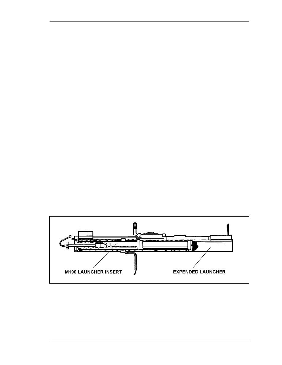
FM 3-23.25
B-1
APPENDIX B
TRAINING DEVICES AND AIDS
Training devices and training aids enable soldiers to learn as much as
they can about a weapon before they try the real thing. This procedure
saves money and time, and it prevents injuries. Training devices both look
and behave like the real weapon, but are cheaper and safer to practice
with. Training aids include anything else used to help soldiers learn to
use a weapon. Trainers should use their imaginations and invent or adapt
other training aids from available resources.
B-1.
LAW SUBCALIBER TRAINING DEVICE
The only M72-series LAW training device designed for individual use is a subcaliber
trainer (Figure B-1). This device, referred to as the M190 subcaliber launcher, is made by
adding an M190 subcaliber conversion kit (NSN 1340-00-420-7999) (Figure B-2) to an
expended M72-series LAW launcher. It is used to fire the M73 subcaliber (35-mm)
rocket. This 36-mm rocket is shorter and lighter than the LAW's 66-mm tactical rocket. It
simulates the tactical rocket's smoke and flight trajectory but with less noise and
backblast. The expended launcher is likely to wear out before the subcaliber inner tube
does. When this happens, the inner tube can be transferred to another expended launcher.
The M190 subcaliber launcher can be used in all training phases, from a fixed firing line
to simulated tactical situations such as a squad live-fire exercise.
NOTE:
The local Training Support Center (TSC) can install the conversion kits, but
DOD Regulation 5100.76-M requires that all sensitive conventional arms,
ammunitions, and explosives, including expended launchers, be carefully
controlled.
Figure B-1. LAW subcaliber trainer.
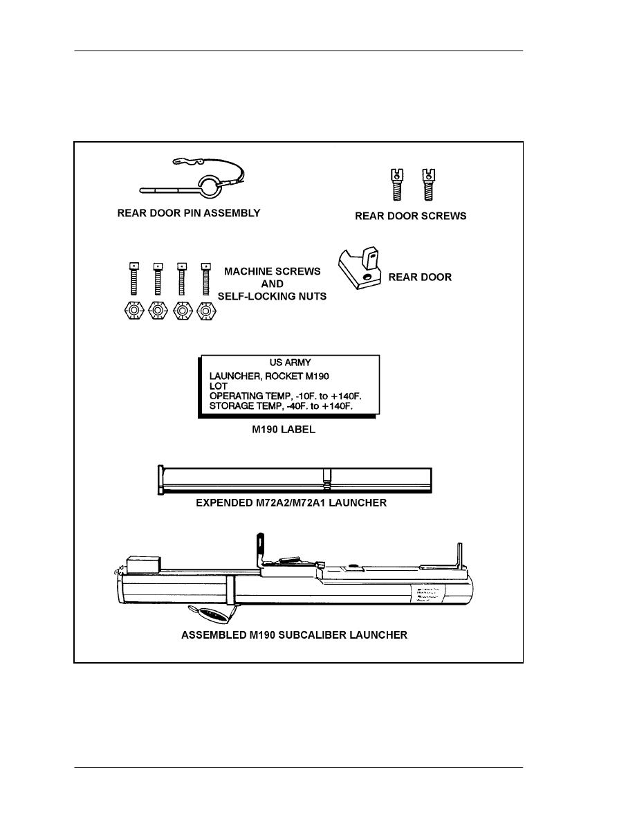
FM 3-23.25
B-2
Figure B-2. M190 subcaliber conversion kit.

FM 3-23.25
B-3
a. Technical Data.
(1) Technical data for the M73 35-mm subcaliber practice rocket are as follows:
Length................................................ 22.48 cm (8.86 inches)
Diameter ............................................ 3.51 cm (1.38 inches)
Weight ............................................... 154 grams (5.39 ounces)
Range................................................. 10 to 250 meters (9.14 to 228.5 yards)
Propellant Charge.............................. 3 tubular grains of M7
Spotting Head Charge ....................... 05 oz (1.5 grams) of composition mix M80
(2) Technical data for the assembled M190 practice rocket launcher are as follows:
Diameter of launcher......................... 12.45 cm (4.9 inches)
Diameter of rocket tube..................... 3.56 cm (1.4 inches)
Weight (with rocket).......................... 2.26 kg (5.02 pounds)
Length of launcher
Extended....................................... 89.9 cm (35.4 inches)
Collapsed ...................................... 64.26 cm (25.32 inches)
Sights................................................. Open, temperature compensating
b. Trigger. This is the same as for the LAW.
c. Sights. These are the same as for the LAW.
d. Operation. The LAW subcaliber training device operates the same as an
M72-series LAW. After the M190 has been loaded, it may remain closed, or it can be
extended and fired. Either way, the procedures are the same as those for the LAW.
e. Loading. To load the M73 rocket into the M190 launcher (Figure B-3)―
(1) Twist and remove the primer housing lockpin and open the primer housing door.
(2) Remove the fired primer block (if present) from the primer block cavity of the
launcher.
(3) Inspect the primer block cavity for obstructions such as primer case stuck on the
firing pin.
(4) Pivot and remove the safety clip from the rocket.
(5) Insert the M73 rocket into the launcher with the primer face up and toward the
firing pin housing.
(6) Guide the primer block into the primer block cavity with the primer toward the
front of the launcher. Close the primer housing door, insert the lockpin across the
primer housing door, and twist to ensure a spring-tight fit. Ensure the primer
housing door fits snugly.
CAUTION
When loading the law subcaliber trainer, ensure the rear cover is
open, the sling assembly is off, and the launcher is collapsed.
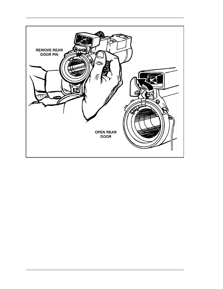
FM 3-23.25
B-4
Figure B-3. Loading the LAW subcaliber launcher.
f. Unloading. To unload the M73 rocket from the M190 launcher—
(1) Return the arming handle to SAFE.
(2) Remove the weapon from your shoulder, keeping the weapon pointed downrange.
(3) Partly collapse the launcher, and remove the primer housing lockpin.
(4) Open the primary housing door, and remove the primer from its housing.
(5) Remove the rocket.
(6) Replace the safety clip on the rocket.
(7) Place the rocket in its original container.
g. Function. The M73 rocket launches the same as tactical rocket, but when the
rocket head strikes the target, it sets off the spotting head that produces a flash, noise, and
white smoke.
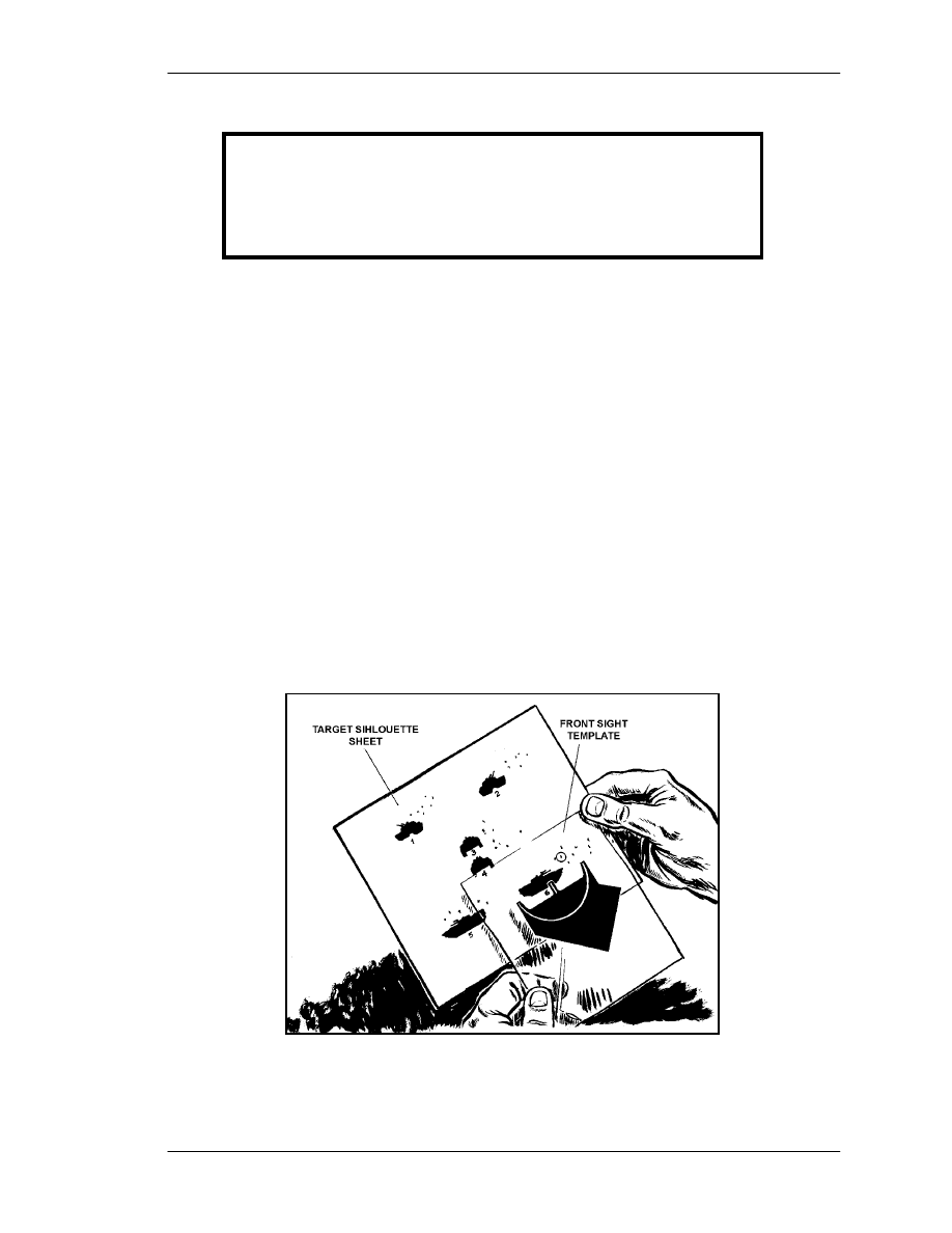
FM 3-23.25
B-5
h. Misfire Procedures. These are the same as for the M-72 series LAW.
i. Range Procedures and Safety. These procedures are the same as for the LAW.
The training device can be used against all solid stationary or moving targets. However,
because the subcaliber rocket can penetrate 0.124 inches (0.315 cm) of steel plate or
8 inches (20.32 cm) of soft wood, the target should be constructed of 3/16-inch steel plate
backed by 3/4-inch plywood.
j. Combat Techniques. These are the same as for the LAW.
B-2.
AT4 FRONT SIGHT TEMPLATE AND TARGET SILHOUETTE SHEET
This graphic training aid (GTA 7-2-5), Sight Engagement Trainer, AT4, consists of two
parts: Part 1, a front sight template, and Part 2, a target silhouette sheet. These are used
together to train soldiers to obtain a correct sight picture. To obtain the correct sight
picture for the target speed and range, the front sight template is placed on the target
silhouette sheet as shown in Figure B-4. For each of the six targets, the reference number
sheet shows the number that should appear in the circle on the front sight template. The
reference number sheet is also used to determine the correct answer for any
unit-developed test concerning Training Objective 12 task, Determine the Correct Sight
Picture for the M136 (AT4). The local TSC can provide GTA 7-2-5.
Figure B-4. Using GTA-7-2-5 with target silhouette sheet
and front sight template.
CAUTION
The M73 subcaliber rocket operates between –23 degrees
and 60 degrees centigrade (-10 degrees and 140 degrees
fahrenheit). Fire it only within this temperature range.
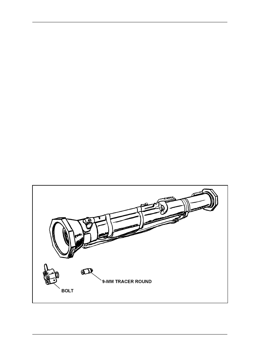
FM 3-23.25
B-6
B-3.
AT4 FIELD HANDLING TRAINER
The AT4 field handling trainer (FHT) is an inert device made from an expended AT4
tactical launcher. It simulates the weight, balance, characteristics, and operation of the
launcher. The FHT is marked with either a gold or yellow 1-inch band between the front
and rear sights, and with the word "DUMMY" in 1-inch letters on the side of the launch
tube. The local TSC can convert expended launchers to training devices, but
DOD Regulation 5100.76-M requires that these items be carefully controlled. The FHT is
appropriate for several training situations that do not require the M287 tracer trainer,
which prevents unnecessary damage to the tracer trainer. The FHT is used in
marksmanship training, FTXs, and institutional training to help soldiers learn how to do
the following:
•
Inspect the AT4 for serviceability.
•
Prepare an AT4 for firing.
•
Demonstrate the correct AT4 firing position.
•
Perform misfire procedures.
•
Return an AT4 to carrying position.
B-4.
AT4 SUBCALIBER TRACER TRAINER
The M287 subcaliber tracer trainer (Figure B-5) uses the 9-mm M939 training
practice-tracer (TP-T) cartridge. When loaded, this trainer simulates the AT4 in weight,
balance, and operation. The velocity and trajectory of its ammunition match that of the
AT4's HEAT cartridge, but the M287 produces less noise, backblast, and overpressure.
The M287 subcaliber tracer trainer is used in place of the AT4 in training.
Figure B-5. M287 subcaliber tracer trainer.
FM 3-23.25
B-7
a. Description. The M287 tracer trainer is a specially constructed AT4. Unlike the
LAW subcaliber trainer, it is not made from an expended launcher, so it has its own NSN.
It is designed to accept a special rifle barrel that fires a reduced-load 9-mm cartridge.
(1) The M287 may be fired at stationary or moving targets. Before it can be fired at a
target tank occupied by personnel, the parts of the tank that could suffer damage must be
shielded. The local TSC can provide specifications for modifying tanks to be used as
targets for the M287 tracer trainer.
(2) Unlike the M136 AT4 itself and the FHT, the M287 has no band between the front
and rear sights. The trainer has a 9-mm submachine gun barrel, a breach assembly, and a
bolt (Figure B-6). The bolt is easily removed to load the 9-mm cartridges and to inspect
the barrel for obstructions.
Figure B-6. M287 barrel assembly and components.
FM 3-23.25
B-8
(3) If the M287 tracer trainer is damaged, the unit armorer can replace its complete
firing mechanism, firing rod, bolt, sights, sling, and 9-mm barrel assembly (Figure B-7).
Figure B-7. Replaceable parts for the M287 tracer trainer.
b. Technical Data. The following technical data apply to the M287 subcaliber tracer
trainer:
Length................................................ 1,020 mm (40 inches)
Weight ............................................... 7 kg (15 pounds)
Action................................................ Mechanical
Sights:
Front ............................................ Three-post system
Rear ............................................. Adjustable range, with two peepholes:
2-mm peephole for daylight and 7-mm
peephole for limited visibility
Operating temperature....................... 10 degrees to 27 degrees Centigrade
..................................................... (0 degrees to 100 degrees Fahrenheit)
Muzzle velocity................................. 300 mps
..................................................... (984 fps)
Caliber ............................................... 9 mm
FM 3-23.25
B-9
c. Ammunition. The M939 9-mm tracer cartridge has a lighter powder charge than
a standard 9-mm bullet. The lighter charge enables the cartridge to closely duplicate the
trajectory of the AT4 tactical round at ranges out to 700 meters. The M939 cartridge also
has a tracer element to enable the firer to compare the impact of the cartridge with the
sight picture. The firer can see the tracer out to 550 meters. Firing the M287 tracer trainer
helps the firer learn the correct sight picture for moving targets. The cartridge's red tip
and half-black base (Figure B-8) distinguishes it from standard 9-mm ammunition, which
should never be fired from the M287 tracer trainer.
Figure B-8. M939, 9-mm tracer cartridge.
d. Function Check. Before the M287 is fired, a function check must be performed
to ensure the trigger and safety mechanisms are operating properly. Function check
procedures are shown in Table B-1. However, before performing a function check,
ensure―
•
The cocking lever is in the safe ("S") position.
•
The transport safety pin is fully inserted, with the lanyard wrapped clockwise
around the launcher.
•
The bolt is removed from the breech.

FM 3-23.25
B-10
STEP
OPERATOR
ACTIONS
FUNCTION
CHECK
CORRECTIVE
MEASURES
1
Try to cock the
tracer trainer
It should not cock
If it cocks, turn the
trainer in for repair
2
Remove the
transport safety
pin and depress
the forward safety
The forward safety
should spring back
when released
If it does not spring
back, turn the tracer
trainer in for repair
3
Cock the firing
mechanism,
pressing only the
red trigger button
The firing rod should
move only slightly and
should be captured by
the safety lever
assembly. No more
than half the rod
should protrude
through the rear of the
firing assembly
If the tracer trainer
fires, turn it in for
repair
4
Recock the firing
mechanism; fully
depress and
continue to hold
down the forward
safety; press the
red trigger button
The tracer trainer
should fire
If the tracer trainer
fails to fire, turn it in
for repair
5
Return the cocking lever to the SAFE position and reinstall the
transport safety pin
Table B-1. Function check, M287 tracer trainer.
e. Loading. The M287 tracer trainer is loaded as follows:
(1) The firer performs the function check and places the M287 tracer trainer on his
shoulder.
(2) The trainer looks through the barrel from the rear to verify that it contains no
obstructions. He inspects the cartridge primer to ensure it is not dented, inserts the bolt
into the breech (Figure B-9), and presses in and turns the bolt clockwise to the "S" to
WARNING
LOAD LIVE AMMUNITION ONLY ON THE FIRING LINE.
NEVER FIRE THE M287 TRACER TRAINER AT HARD
TARGETS LESS THAN 125 METERS FROM THE FIRING
LINE. REMAIN CLEAR OF THE FRONT OF THE M287,
WHICH MUST BE POINTED DOWNRANGE AT ALL TIMES.
FM 3-23.25
B-11
place it in the safe position (Figure B-10). Then he arms the tracer trainer by turning the
bolt clockwise to "F" so that it can be fired (Figure B-11).
(3) With the launcher still on his shoulder, the firer cocks the launcher by placing the
cocking lever in the cocked position.
Figure B-9. Inserting bolt with cartridge into
the breech of the M287 tracer trainer.
Figure B-10. Ensuring tracer trainer bolt is in the safe position.
Figure B-11. Arming the tracer trainer.
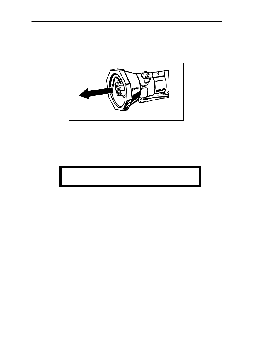
FM 3-23.25
B-12
f. Unloading. With the tracer trainer still on the firer's shoulder, the trainer or
instructor removes the bolt by turning it counterclockwise past the "S," then pulling the
bolt from the breech (Figure B-12). If more rounds are to be fired, he removes the
expended cartridge and reloads the bolt.
Figure B-12. Unloading the tracer trainer.
g. Reloading. With the tracer trainer still on his shoulder, the firer places the
cocking lever in the safe position, keeping the tracer trainer on his shoulder and pointing
toward the target. The trainer reloads the tracer trainer and prepares it for firing.
h. Misfire Procedures. In the event of a misfire
(1) Immediately shout "Misfire!"
(2) Release the forward safety, recock the launcher, and ensure the cocking lever is
erect. Fully depress and hold down the forward safety, then aim and press the red trigger
button.
(3) If the tracer trainer still fails to fire, repeat the two previous steps.
(4) If the launcher fails to fire again, release the forward safety, maintain your firing
position, and return the cocking lever to the safe position.
(5) Notify the training supervisor.
(6) If a real misfire occurs that cannot be corrected by following the steps previously
discussed, the trainer or assistant trainer on duty must ensure the cocking lever is in the
safe position and that the forward safety is in the vertical position. He must then insert
the transport safety pin and remove and inspect the cartridge. If the primer is dented, he
replaces it, disposing of the old one IAW range safety SOP. If the primer is not dented, he
notifies DS maintenance to inspect the bolt firing pin for damage. He then reloads the
tracer trainer and continues the training exercise.
i. Range Procedures and Safety. These are the same as for the M136 AT4.
DANGER
NEVER TOUCH THE TRIGGER WHILE RELOADING.

FM 3-23.25
C-1
APPENDIX C
PERFORMANCE EVALUATIONS
The trainer administers performance evaluations to determine how
much training the soldiers have learned. Those who fail are retrained and
retested, and those who pass help retrain and evaluate those who did not.
Instructions are given for right-handed firers: the M136 AT4 may only be
fired right-handed, but the M72-series LAW may be fired left-handed, if
procedures are reversed. Tasks are generic to both light antiarmor
weapons. Conditions and standards may also be generic but, if not, are
given by weapon.
TASK 1: Perform serviceability checks on a light antiarmor weapon.
CONDITIONS: Given an expended light antiarmor weapon under suitable conditions or
in an appropriate location.
M72-Series LAW
STANDARDS: The firer performs the following actions:
TRAINING AND EVALUATION
1. Inspects the launcher to ensure it has no cracks, dents, or bulges.
2. Ensures the trigger arming handle is present and in the SAFE position.
3. Checks the rubber boots around the trigger bar and detent for cracks, tears, and
deterioration.
4. (M72A2 only) Inspects the data plate on the right forward side of the launcher to
ensure the words "with coupler" appear on the first line. If not, informs the trainer.
M136 AT4
STANDARDS: The firer performs the following actions:
TRAINING AND EVALUATION
1. Ensures the launcher has no cracks, dents, or bulges, or reports these defects to the
instructor.
2. Ensures the transport safety pin is in place, or reports this defect to the instructor.

FM 3-23.25
C-2
3. Ensures the cocking lever is in the SAFE (uncocked) position, or reports this defect to
the instructor.
4. Ensures the muzzle cover is intact, or reports this defect to the instructor.
5. Ensures the color-coded band is correct, or reports this defect to the instructor.
6. Ensures the sights function properly, or reports this defect to the instructor.
7. Ensures the venturi has no foreign objects, or reports this defect to the instructor.
8. Ensures the forward safety functions properly, or reports this defect to the instructor.
9. Ensures the red trigger button is not broken or missing, or reports this defect to the
instructor.
10. Ensures the shoulder stop is not broken or damaged, or reports this defect to the
instructor.
11. Ensures the carrying sling is not frayed and is firmly attached to the launch tube, or
reports this defect to the instructor.
RESULTS GO NO-GO
Critique and grade the soldier.
TASK 2: Place a light antiarmor weapon into operation.
CONDITIONS: Given an expended light antiarmor weapon (FHT) on a range or in
garrison.
M72-Series LAW
STANDARDS: The firer performs the following actions, in sequence:
TRAINING AND EVALUATION
1. Removes the rear cover pull pin.
2. Releases the rear cover and sling assembly.
3. Extends the launcher vigorously and ensures it is fully extended.
4. Places the launcher on his firing shoulder.

FM 3-23.25
C-3
5. Checks the backblast area.
6. Pulls the arming handle out.
7. Sights.
M136 AT4
STANDARDS: The firer performs the following actions, in sequence:
TRAINING AND EVALUATION
1. Cradles the AT4 in his arms.
2. Removes the transport safety pin.
3. Unsnaps and unfolds the shoulder stop.
4. Places the AT4 on his shoulder.
5. Releases the sights.
6. Checks the backblast area.
7. Places cocking lever in the ARMED (cocked) position.
8. Fully depresses and holds down the forward safety.
RESULTS GO NO-GO
Critique and grade the soldier.
TASK 3: Demonstrate the standing position used to fire a light antiarmor weapon.
CONDITIONS: Given a target and an expended light antiarmor weapon in any suitable
location.
STANDARDS: The firer demonstrates the standing position as follows:

FM 3-23.25
C-4
TRAINING AND EVALUATION
M72-Series LAW
1. Faces the target by executing a half-left face turn and spreading feet a comfortable
distance apart.
2. Places the launcher on the shoulder with the left hand directly under the forward
portion of the launcher.
3. Places the right elbow against the body for stability.
M136 AT4
1. Faces the target by executing a half-left face turn and spreads the feet a comfortable
distance apart.
2. Places the launcher on the shoulder and grasps the sling near the launcher's muzzle
with the left hand.
3. Places the right elbow against the body for stability.
RESULTS GO NO-GO
Critique and grade the soldier.
TASK 4: Demonstrate the kneeling position used to fire a light antiarmor weapon.
CONDITIONS: Given a target and an expended light antiarmor weapon in a suitable
location, with the soldier in the standing position.
STANDARDS: The firer demonstrates the kneeling position as follows:
TRAINING AND EVALUATION
1. Kneels on the right knee with the right thigh at a 90-degree angle to the line of aim.
2. Sits back on the right heel and shifts weight forward.
3. Rests the upper left arm forward of the left knee.
4. Places the right arm against the body.

FM 3-23.25
C-5
RESULTS GO NO-GO
Critique and grade the soldier.
TASK 5: Demonstrate the sitting position used to fire a light antiarmor weapon.
CONDITIONS: Given a light antiarmor weapon training device or expended launcher in
a suitable location, with the soldier in the standing position.
STANDARDS: Each firer demonstrates the sitting position as follows:
TRAINING AND EVALUATION
1. Keeps the launcher pointed toward the target.
2. Executes a half-left face turn and sits with the legs crossed.
3. Places the launcher on the right shoulder.
4. Leans slightly forward from the hips.
5. Rests the elbows forward of the knees to avoid bone-to-bone contact.
RESULTS GO NO-GO
Critique and grade the soldier.
TASK 6: Demonstrate the prone position used to fire a light antiarmor weapon.
CONDITIONS: Given a target and an expended light antiarmor weapon (FHT) in a
suitable location.
STANDARDS: The firer demonstrates the prone position as follows:
TRAINING AND EVALUATION
1. To keep clear of the backblast area, lies down at an angle of not less than 45 degrees
from the line of fire.
2. Keeps back straight and right leg directly on line with the right hip and right shoulder.
3. Moves left leg as far as possible to ensure comfort.
4. Holds both elbows well below the launcher.

FM 3-23.25
C-6
5. Checks the backblast area to ensure that no part of the body is in it.
6. Holds head as steady as possible, with the firing eye lined up with the sights.
RESULTS GO NO-GO
Critique and grade the soldier.
TASK 7: Identify enemy vehicles and weapons.
CONDITIONS: Given ten vehicle identification cards (GTA 17-2-13).
STANDARDS: The soldier correctly identifies eight out of ten vehicles or weapons by
nomenclature.
RESULTS GO NO-GO
Critique and grade the soldier.
TASK 8: Estimate range.
CONDITIONS: Given stationary, partly exposed, or fully exposed targets at ranges
between 50 and 250 meters, during daylight, in weather conditions where all targets are
visible. Targets include personnel, equipment, silhouettes, and vehicles.
STANDARDS: The soldier states the distance to each target with no more than
20 percent error.
RESULTS GO NO-GO
Critique and grade the soldier.
TASK 9: Apply the correct lead for a target.
CONDITIONS: Given a sight template, a series of ten flank, frontal, and oblique
silhouettes of armored targets, rates of movement, and ranges. (At least three different
views, speeds, and ranges are given.)
STANDARDS: The soldier uses correct sighting procedures and correctly applies the
lead eight out of ten times.

FM 3-23.25
C-7
RESULTS GO NO-GO
Critique and grade the soldier.
TASK 10: Perform misfire procedures on a light antiarmor weapon.
CONDITIONS: Given a previously fired light antiarmor weapon and instructions that
the weapon has misfired, on a suitable firing range, under simulated combat conditions,
in any lighting conditions.
M72-series LAW
STANDARDS: The soldier applies misfire procedures as follows and tries to fire the
M72-series LAW. If the weapon still fails to fire, he disposes of it IAW unit SOP:
TRAINING AND EVALUATION
1. Immediately squeezes the trigger bar again.
2. If the LAW still does not fire, tries to place the trigger arming handle on SAFE.
3. Removes the launcher from the shoulder and partly collapses it (10 to 15 centimeters
or 4 to 6 inches), keeping the launcher pointed upward and downrange.
4. Extends the launcher.
5. If the LAW fails to fire again, squeezes the trigger, tries to return the weapon to
SAFE, partly collapses the launcher, and sets the weapon aside.
M136 AT4
STANDARDS: The soldier performs combat misfire procedures on the AT4 as follows:
TRAINING AND EVALUATION
1. Releases the forward safety with the right hand.
2. Recocks the firing mechanism using the cocking lever.
3. Presses and holds down the forward safety, aims, and presses the trigger.
4. If launcher still fails to fire, repeats Steps 1 and 2.

FM 3-23.25
C-8
5. If the launcher again fails to fire, returns the cocking lever to the SAFE (uncocked)
position.
6. Removes the weapon from the shoulder, keeping it pointed toward the target.
7. Replaces the transport safety pin.
8. Informs the instructor that the firer breaks the sights off to indicate a misfired weapon
when in combat.
9. Places the launcher on the ground, pointing toward the target.
RESULTS GO NO-GO
Critique and grade the soldier.
TASK 11: Return the light antiarmor weapon to its carrying configuration.
CONDITIONS: Given an expended light antiarmor weapon in a suitable location.
STANDARDS: The soldier performs the following actions, in sequence:
M72-series LAW
TRAINING AND EVALUATION
1. Pushes in the trigger arming handle.
2. Removes the launcher from the shoulder.
3. Depresses the barrel detent and collapses the launch tube, guiding the front and rear
sights into position.
4. Replaces the sling assembly.
5. Replaces the rear cover pull pin.
M136 AT4
1. Releases the forward safety.
2. Returns the cocking lever to the SAFE (uncocked) position by pushing forward and
upward on it, then letting it spring back into position.

FM 3-23.25
C-9
3. Removes the launcher from the shoulder, ensuring the muzzle is pointed in the
direction of fire.
4. Replaces the transport safety pin, fully seating it in the retainer hole.
5. When closing the rear sight, resets the range indicator to the 200-meter setting. (If
this step is not accomplished, the rear sight breaks off when the sight cover is closed.)
6. Restores the sights by laying them down and closing their covers.
7. Snaps the shoulder stop into the closed position.
8. Moves to another location; slings the launcher over either shoulder and moves out.
RESULTS GO NO-GO
Critique and grade the soldier.
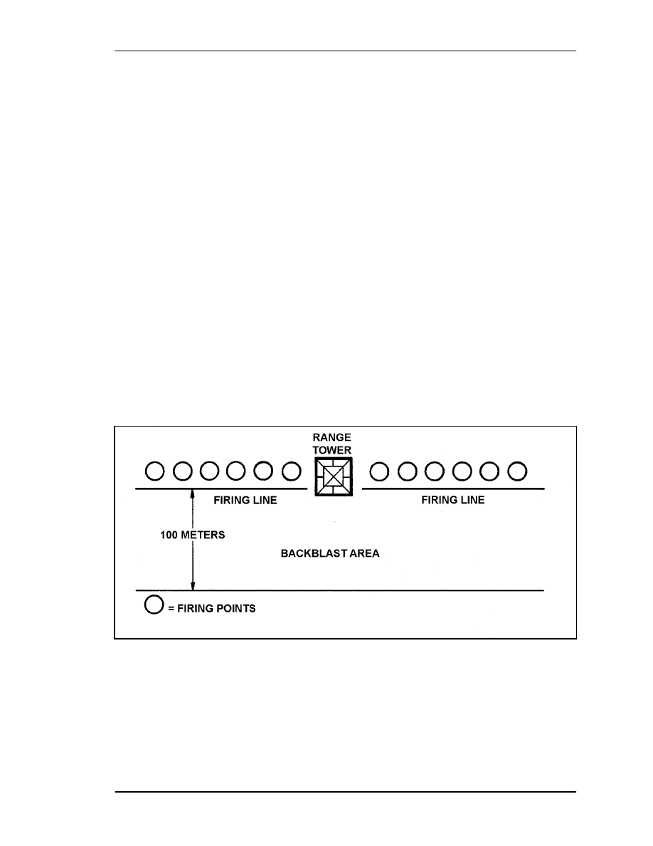
FM 3-23.25
D-1
APPENDIX D
SUGGESTED DESIGN FOR COMBINED LIGHT
ANTIARMOR RANGE
This appendix provides basic guidance for units to establish a range
complex for light antiarmor weapons. The complex described may be used
for multilevel training and firing of light antiarmor weapons; both
subcaliber trainers and live HE ammunition may be used on the same
range. Training areas should be near, but not adjacent to, the firing line.
The firing line should be designed to allow personnel to observe firing
from the side. The target array should include stationary targets composed
of F-type targets or the hulls of hard targets (APCs or tanks), a moving
target (a target on track or a manned moving target tank [MMTT]), and
bunkers. This allows the firer to engage a variety of targets and to develop
his skills in the various types of engagements.
D-1.
FIRING LINE
The firing line should be organized to allow for the 100-meter AT4 backblast
(Figure D-1). Also, at least 20 meters must be allowed between firing points. The
backblast area must be fenced, roped, or marked in some way, so soldiers know not to
enter it when firing is being conducted. A range that meets the requirements of the AT4
will also meet the requirements of the LAW.
Figure D-1. Firing line.
D-2.
TARGET ARRAY
The target array should include targets at ranges of 100 to 700 meters (Figure D-2). This
enables the unit to conduct advanced instructional fire on targets located beyond the
weapons' maximum effective ranges. Standard vehicle silhouettes or tank hulls should be
used for stationary targets. Selected targets should be positioned behind mounds of earth
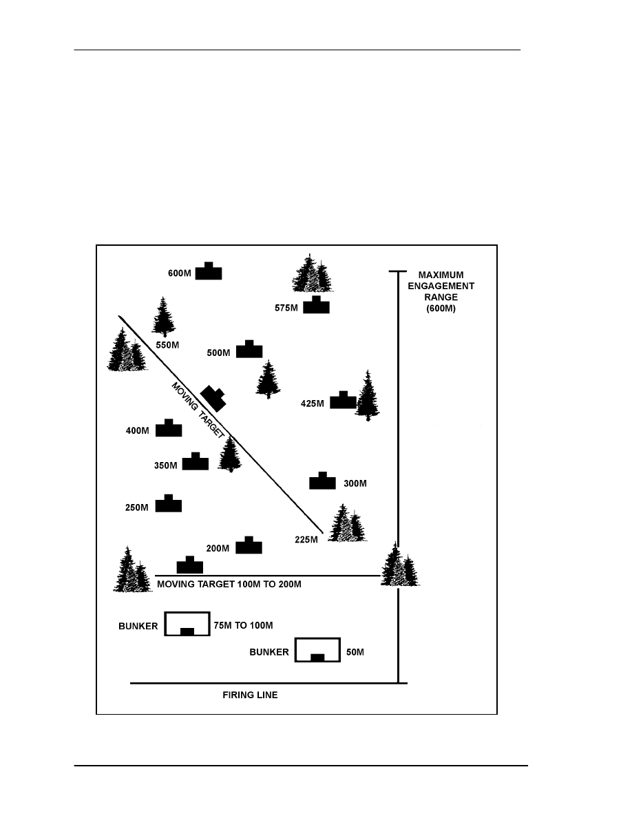
FM 3-23.25
D-2
to simulate vehicles in defilade or partly behind trees or other objects. Firers adjust their
points of aim accordingly. Targets should also be positioned to allow firers to engage
flank, frontal, and oblique targets. Bunker targets should be placed within the target array
at ranges of 100 to 400 meters. Bunker targets should be no more than 1 meter high or
2 1/2 to 3 meters wide. Moving target silhouettes should travel along a track or road so
the firers can engage fast moving targets from both flank and oblique angles. The moving
targets should be placed at ranges of 150 to 600 meters and should enter and exit from the
flanks outside the range fan. Firers may only use HE weapons to engage hard targets.
This reduces the damage to other targets the unit must maintain such as F-type silhouettes
and bunkers.

FM 3-23.25
D-3
Figure D-2. Target array.

FM 3-23.25
E-1
APPENDIX E
FIRING TABLES AND EXAMPLE SCORECARDS
This appendix provides firing tables for the subcaliber gunnery
trainers discussed in this manual. It also includes an example of a
completed scorecard for each light antiarmor weapon. All instructional
and qualification firing tables are conducted on suitable ranges with
ammunition designated in the firing tables. Some tables are fired in
daylight, others in limited visibility, but all have some NBC firing
(Table E-1).
Instructional day fire, stationary targets
M72-Series LAW
Instructional day fire, moving targets
Instructional night fire
Instructional fire
Instructional night fire
M136 AT4
Qualification fire
Qualification night fire
Advanced instructional fire
Table E-1. Firing tables for light antiarmor weapons.
E-1.
M72-SERIES LAW
The M190 35-mm subcaliber device is used to fire the instructional firing tables for the
M72-series LAW and DA Form 7323-R (M72-Series LAW Scorecard) is used to score
them. Figure E-1 shows an example of the completed form. The instructional day and
night firing tables for the LAW are provided in Tables E-2 and E-3.
NOTE:
A blank copy of the form is located at the end of this publication for local
reproduction on 8 1/2-inch by 11-inch paper.
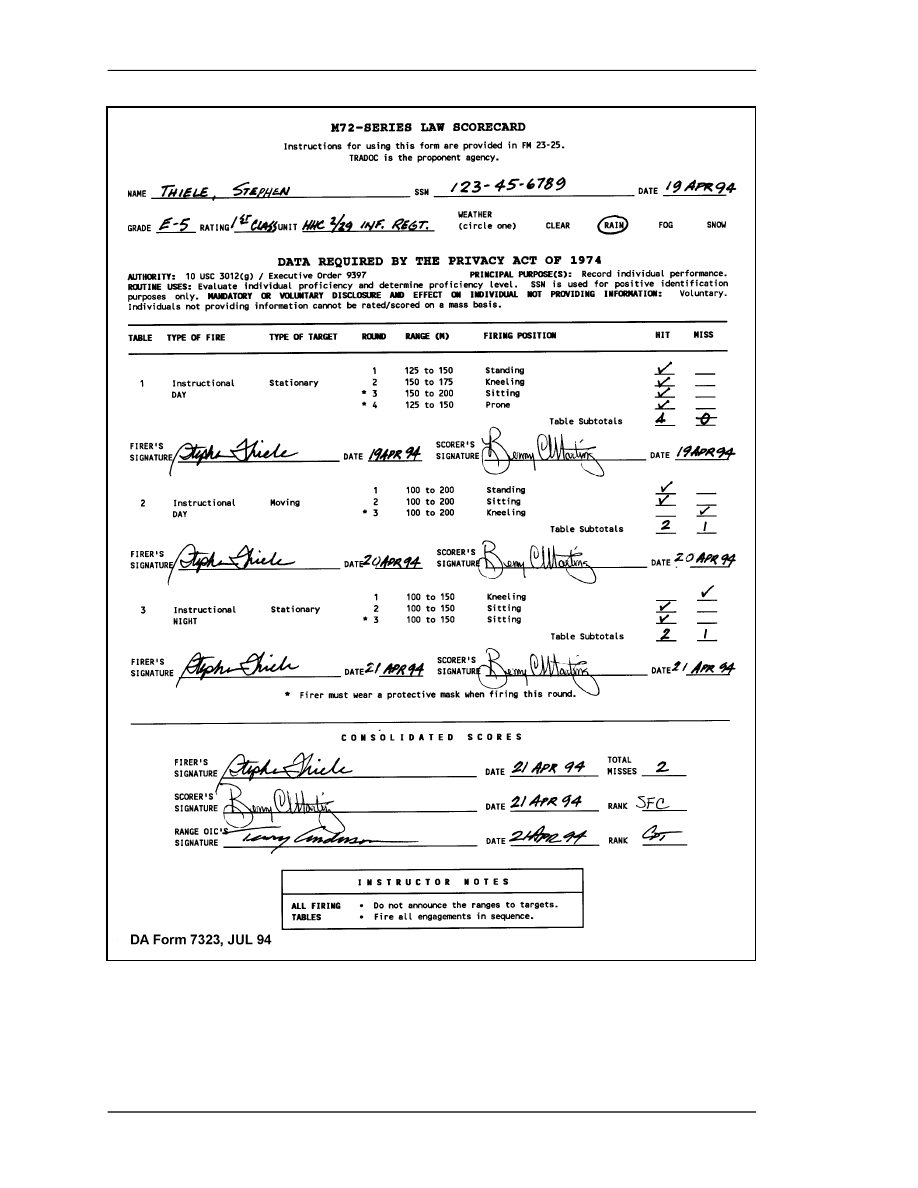
FM 3-23.25
E-2
Figure E-1. Example completed DA Form 7323-R.

FM 3-23.25
E-3
TABLE 1
M72-Series LAW Instructional Day Fire,
Stationary Targets
TASK
Each soldier engages stationary armored targets with the
M190 subcaliber device.
CONDITIONS
Given one M190 subcaliber device and four M73 rockets, on
a suitable firing range with stationary targets at a range of
100 to 225 meters. Two targets are engaged in MOPP4.
STANDARD
The soldier fires four rockets at stationary targets and
achieves at least three hits.
TABLE 2
M72-Series LAW Instructional Day Fire,
Moving Targets
TASK
Each soldier engages moving armored targets with the M190
subcaliber device.
CONDITIONS
Given one M190 subcaliber device, three M73 rockets, and
targets moving at a rate of 8 to 24 kmph and at a range of
100 to 200 meters. Frontal and oblique-moving targets may
be used when a manned, moving tank is available. One
target is engaged in MOPP4.
STANDARD
The soldier fires three rockets at moving targets and achieves
at least two hits.
Table E-2. Instructional day firing tables for the M72-series LAW.
TABLE 3
M72-Series LAW Instructional Night Firing
Before you can use the AN/PVS-4, you must install an M72A1 sight reticle on it and
Boresight it to an expended M72-series LAW launcher.
TASK
Each soldier engages stationary targets at night with the
M190 subcaliber device.
CONDITIONS
Given one M190 subcaliber device and three M73 rockets,
on a suitable firing range with stationary targets at a range of
100 to 150 meters, at night, and either an AN/PVS-4 or
illumination provided by indirect fire.
STANDARD
The soldier fires three rockets at stationary targets and
achieves at least one hit. He engages one of these targets in
MOPP4.
Table E-3. Instructional night firing table for the M72-series LAW.

FM 3-23.25
E-4
E-2.
M136 AT4
The M287 9-mm tracer bullet trainer is used to fire the instructional, qualification, and
advanced instructional firing tables for the M136 AT4 and DA Form 7324-R (M136 AT4
Scorecard) is used to score them. A copy of this form is located at the end of this publication
for local reproduction on 8 1/2-inch by 11-inch paper. Figure E-2 shows an example of the
completed form; Tables E-4 through E-6, on pages E-7, E-8, and E-9, provide the
instructional, qualification, and advanced instructional firing tables for the AT4. The latter
must be fired on a separate, more specialized range.
E-3.
NIGHT COURSE OF FIRE TABLES AND QUALIFICATION FOR M136
AT4
Each soldier is given a PMI before the instructional and qualification tables are fired. Once
the soldier completes Table I and III (day tables), he is given additional instruction on the use
of the aided vision devices for the night operations.
a. Qualification Tables for the M287 Tracer Trainer.
•
Table I (Instructional Day). This scenario consists of 12 targets from 100 to
300 meters. The standard to proceed to the next table is 6 out of 12 targets
successfully engaged.
•
Table II (Instructional Night). This scenario consists of 8 targets from 100 to
300 meters. The standard to proceed to the next table is 6 out of 12 targets
successfully engaged at night.
•
Table III (Qualification Day). This scenario consists of 8 targets from 100 to
300 meters. The standard to proceed to the next table is 6 out of 8 targets
successfully engaged.
•
Table IV (Qualification Night). This scenario consists of 8 targets from 100 to
300 meters (same as Table III, but conducted at night). The standard to proceed
to the advanced firing tables is 6 out of 8 targets successfully engaged.
NOTES: 1. In Table IV, eight engagements are proposed as opposed to the current six
engagements.
2. All references to the M136 launcher and cartridge refer to the M287 9-mm
tracer bullet training device.
b. Ammunition Requirements for Night Training Strategy. The current STRAC
ammunition allocation and course of fire is compared with the proposed night training
strategy in Table E-7 on page E-9. The current STRAC table stipulates that 120 rounds of 9-
mm tracer ammunition is authorized to each squad for additional squad members to fire
Tables I and IV.
c. Day Standards. Commanders are able to achieve the current day standard at night
with the M136 AT4 through the use of training strategy within this field manual. A gunner
who is qualified on the day standard and has executed preliminary marksmanship training
with the appropriate night vision device can achieve the current day standard at night.
During testing, gunners had no problem engaging targets out to 300 meters. Table E-8, on
page E-9, shows the day standard and is also the proposed night standard.
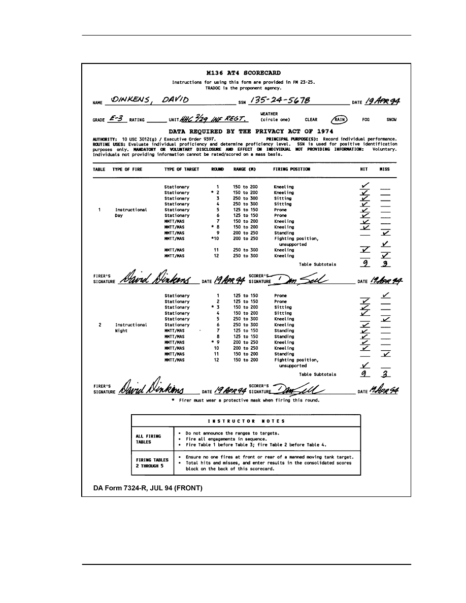
FM 3-23.25
E-5
•
Figure E-2. Example completed DA Form 7324-R (front).
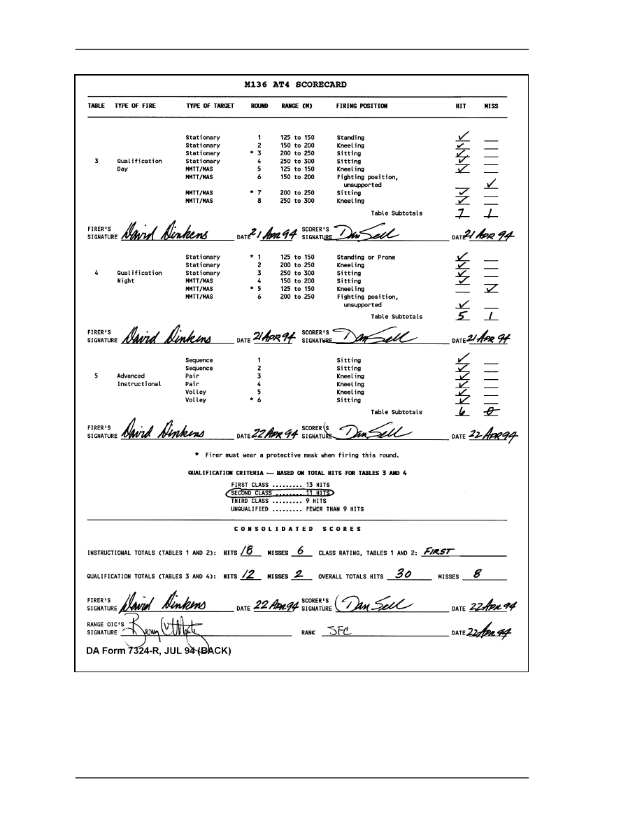
FM 3-23.25
E-6
Figure E-2. Example completed DA Form 7324-R (back).

FM 3-23.25
E-7
TABLE 1
M136 AT4 Instructional Fire
TASK
Each soldier engages an armored target with the M287 tracer
bullet trainer.
CONDITIONS
Given one M287 9-mm subcaliber device and twelve rounds of
9-mm tracer ammunition, a suitable firing range, stationary
targets at a range of 100 to 300 meters, and other targets
moving 8 to 24 kmph at a range of 150 to 200 meters. When a
manned, moving tank is available, frontal and oblique-moving
targets may be used.
STANDARD
The soldier fires twelve tracer bullets at stationary and moving
targets. He engages three of these targets in MOPP4.
TABLE 3
M136 AT4 Instructional Fire
TASK
Each soldier engages an armored target with the M287 tracer
bullet trainer at night.
CONDITIONS
At night, given one M287 9-mm subcaliber device and twelve
rounds of 9-mm tracer ammunition, artificial illumination, a
suitable firing range, stationary targets at a range of 100 to 300
meters, and other targets moving from 8 to 24 kmph (5 to 15
mph) at a range of 150 to 200 meters. When a manned,
moving tank is available, frontal and oblique-moving targets
may be used.
STANDARD
The soldier fires twelve tracer bullets at stationary and moving
targets. He engages two of these targets in MOPP4.
Table E-4. Instructional firing tables for the M136 AT4.

FM 3-23.25
E-8
TABLE 2
M136 AT4 Qualification Fire
TASK
Each soldier engages an armored target with the M287
tracer bullet trainer.
CONDITIONS
Given one M287 9-mm subcaliber device and eight
rounds of 9-mm tracer ammunition, a suitable firing
range, stationary targets at a range of 100 to 300
meters, and other targets moving at a rate of 8 to
24 kmph (5 to 15 mph) at a range of 150 to 200
meters. When a manned, moving tank is available,
frontal and oblique-moving targets may be used.
STANDARD
The soldier fires eight tracer bullets at stationary and
moving targets and achieves at least six hits. He
engages two of these targets in MOPP4.
TABLE 4
M136 AT4 Qualification Fire
TASK
Each soldier engages an armored target with the M287
tracer bullet trainer.
CONDITIONS
At night, given one M287 9-mm subcaliber device and
six rounds of 9-mm tracer ammunition, artificial
illumination, a suitable firing range, stationary targets at
a range of 100 to 300 meters, and other targets moving
8 to 24 kmph (5 to 15 mph) at a range of 150 to 200
meters. When a manned, moving tank is available,
frontal and oblique-moving targets may be used.
STANDARD
At night, given one M287 9-mm subcaliber device and
six rounds of 9-mm tracer ammunition, artificial
illumination, a suitable firing range, stationary targets at
a range of 100 to 300 meters, and other targets moving
8 to 24 kmph (5 to 15 mph) at a range of 150 to 200
meters. When a manned, moving tank is available,
frontal and oblique-moving targets may be used.
Table E-5. Qualification firing tables for the M136 AT4.

FM 3-23.25
E-9
TABLE 5
M136 AT4 Advanced Instructional Fire
Fire this table on an appropriate separate, specialized range.
TASK
Each soldier engages an armored target with the M287 tracer
bullet trainer.
CONDITIONS
Given one M287 9-mm subcaliber device and six rounds of
9-mm tracer ammunition, a suitable firing range, stationary
targets at a range of 100 to 300 meters, and other targets
moving 8 to 24 kmph (5 to 15 mph) at a range of 150 to 200
meters. When a manned, moving tank is available, frontal and
oblique-moving targets may be used.
STANDARD
The soldier must fire six tracer bullets at stationary and moving
targets and achieve at least three hits. He must engage two of
the targets with sequence firing, two with pair firing, and two
with volley firing, and he must observe MOPP4 while engaging
one of the six.
Table E-6. Advanced instructional firing table for the M136 AT4.
EVENT
CURRENT
STRAC
RECOMMENDED
CHANGES
TOTAL
TABLE I
12
0
12
TABLE II
12
0
12
TABLE III (QUALIFICATION)
8
0
8
TABLE IV (NIGHT QUALIFICATION)
6
2
8
TABLE V (ADVANCE)
6
0
0
TOTAL
44
2
40
Table E-7. Ammunition requirements for night training strategy.
M136 AT4 (M287 TRAINER) TABLE III/IV
ENGAGEMENT
RANGE
POSITION
HIT/MISS
1
125 to 150
Standing
2
150 to 200
Kneeling
3
200 to 250
Sitting
4
250 to 300
Sitting
5
125 to 150
Kneeling
6
150 to 200
Fighting Position
7
200 to 250
Sitting
8
250 to 300
Kneeling
Table E-8. M136 AT4 (M287 trainer) Table III/IV.

FM
3-23.25
APPENDIX F
INFRARED LASER AIMING DEVICES
The newest infrared laser pointers increase the night firing accuracy
of infantry weapons. The new family of weapon mounts (some fielded with
the thermal weapon sight) and helmet brackets are more stable and
reliable for continued accurate firing under field conditions. Their
effectiveness is limited by the capability of the image-intensifying (I
2
) sight
with which they are used. Normally this is a night vision goggle or
monocular, with or without the 3X magnifier. Again, they primarily
enhance the gunner’s ability to align his sights on the target, but usually
have dramatic affect on his firing positions and scanning technique.
Unlike I
2
sights mounted on the weapon, the gunner can somewhat reduce
the adverse effects of muzzle flash by rising up higher off the sight with his
helmet-mounted goggle or monocular. With the AN/PEQ-2A, the range of
these devices is greatly improved, allowing great effectiveness for crew-
served weapons out to 2,200 meters. However, trainers and leaders must
adopt new safety procedures to ensure these lasers, which are not safe for
the eyes, are treated like loaded weapons any time the batteries are issued.
Finally, the bore light is also effective to boresight these pointers.
Generally weapons do not require zeroing with live ammunition to
confirm alignment after soldiers and leaders are qualified in the
boresighting techniques. The AT4 cannot be conventionally boresighed,
therefore a sight alignment method is used to zero the aided vision device.
F-1. AN/PAQ-4C, AIMING LIGHT
The AN/PAQ-4C aiming light (Figure F-1) projects an infrared laser beam, which cannot
be seen with the eye but can be seen with night vision devices. This aiming light works
with the AN/PVS-7B/C/D-series goggles and AN/PVS-14. The AN/PAQ-4C mounts on
various weapons with mounting brackets and adapters.
a.
Technical Data. The following technical data apply to the AN/PAQ-4C:
Optics:
100%
parallax
free,
anti-reflective coated lens system
Length (sight):
14 centimeters (5.5 inches)
Weight: 164
grams
(5.78
ounces)
Height: 3
centimeters
(1.2
inches)
Width:
6.5
centimeters
(2.5
inches)
Ranged: Beyond
600
meters.
(Actual range depends on light level and
night
vision
device
used
for
observation.)
Battery life:
100-hour operating (ON) time for AA batteries in temperatures
above 0 degrees Centigrade (32 degrees Fahrenheit); 36 hours
for temperatures below 0 degrees Centigrade (32 degrees
Fahrenheit)
F-1
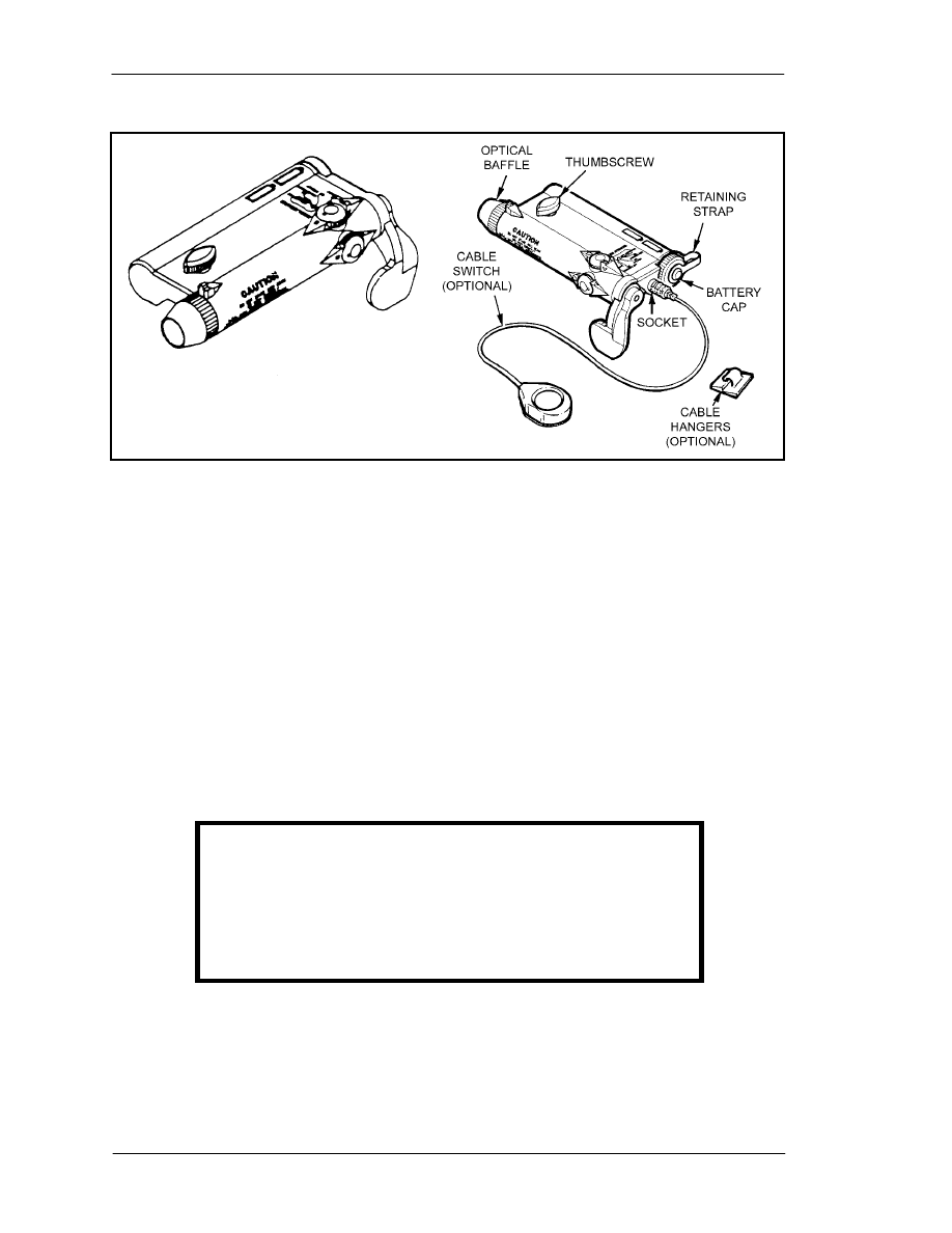
FM 3-23.25
Figure F-1. AN/PAQ-4C, aiming light.
b.
Operation. Activate the AN/PAQ-4C aiming light by rotating the ON/OFF
switch lever or the button on the optional cable switch. Either switch connects power
from two AA batteries to an internal electronic circuit, which produces the infrared laser.
Internal lenses focus the infrared light into a narrow beam. Control the direction of the
beam by rotating the mechanical adjusters with click detents. These adjusters are used to
zero the aiming light to the weapon. Once zeroed to the weapon, the aiming light projects
the beam along the line of fire of the weapon. The optical baffle prevents off-axis
viewing of the aiming light beam by the enemy.
(1)
M136 (AT4) Launcher and Cartridge Mounting Procedures. The aiming light is
attached to the M136 (AT4) launcher and cartridge by first attaching the mounting
bracket to the weapon and then attaching the aiming light to the mounting bracket
(Figures F-2 and F3).
STEP 1: Install the mounting bracket.
NOTE:
All references to the M136 (AT4) launcher and cartridge are also applicable to
the M287 9-mm tracer bullet training device.
WARNING
Only M136 (AT4) qualified personnel should install and
use the mounting bracket assembly. Conduct all M136
(AT4) operator preventive maintenance checks and
services before installation of mounting bracket
assembly.
(a) Cradle the M136 (AT4) in left arm.
(b) Position the support bracket with the mounting rail on the left side and the
marking FRONT over the rear sight.
F-2
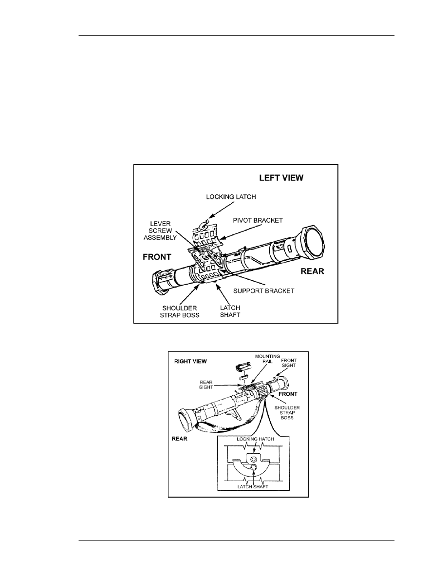
FM
3-23.25
(c) With the pivot bracket spread open, place the support bracket against the base of
the rear sight housing and the bottom on the shoulder strap boss.
(d) Swing the pivot bracket around the M136 (AT4) and secure it by rotating the
locking latch clockwise to engage the latch shaft.
(e) The lever screw assembly must be located in the rear threaded screw hole when
mounting the aiming light. Lever screw assembly may require relocation from the front to
the rear threaded screw hole.
(f) Place the bracket adapter (Figure F-2) in groove of the mounting rail so that the
threaded screw hole in the base of the adapter is aligned with the lever screw assembly
and tighten the lever screw.
Figure F-2. M136 (AT4) installation.
Figure F-3. M136 (AT4) installation (locking latch and shaft).
F-3
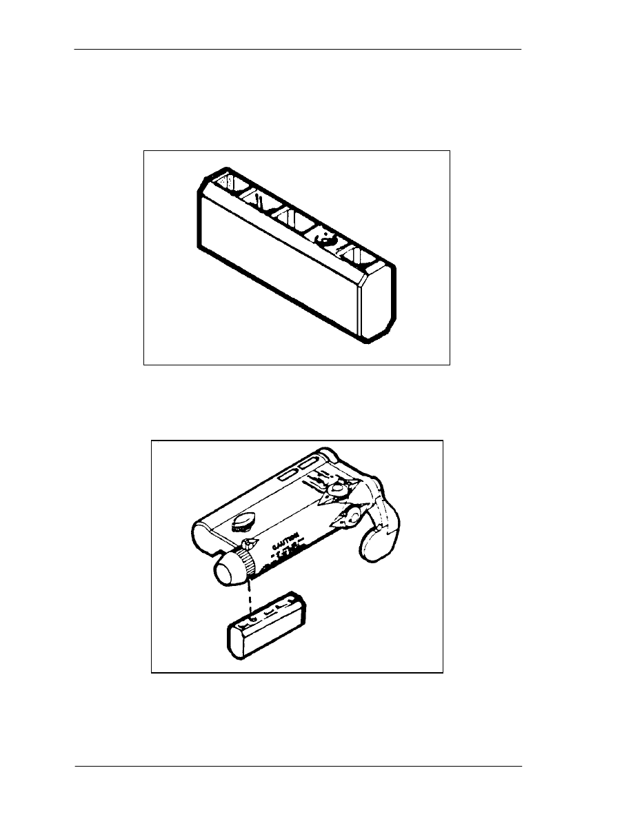
FM 3-23.25
STEP 2: Install the bracket adapter (Figure F-4). The bracket adapter provides
compatibility between the aiming light and the mounting brackets used on the M2, M60,
and M136 AT4 weapons.
Figure F-4. Bracket adapter.
STEP 3: Attach the AN/PAQ-4 onto the bracket adapter (Figure F-5).
Figure F-5. Attaching bracket adapter to aiming light.
F-4

FM
3-23.25
STEP 4: Attach the AN/PAQ-4 to the AN/PVS-4 mounting bracket.
•
Position the AN/PAQ-4 on top of the bracket so that the spacer of
the AN/PAQ-4 is aligned with the mounting knob of the bracket.
•
Turn the mounting knob clockwise until the AN/PAQ-4 is tight.
WARNING
Do not store the AN/PAQ-4 with batteries installed.
(2)
M136 (AT4) Launcher and Cartridge Dismounting Procedures.
STEP 1: Detach the AN/PAQ-4 from the AN/PVS-4 mounting bracket.
•
Turn the mounting knob counterclockwise until the AN/PAQ-4 is
loose.
•
Remove the AN/PAQ-4 from the bracket adapter.
STEP 2: Remove the adapter from the AN/PAQ-4
STEP 3: Remove the mounting bracket.
•
Rotate the locking latch counter clockwise to disengage the latch
shaft.
•
Swing pivot bracket away from around the AT4.
F-2. AN/PEQ-2A TARGET POINTER/ILLUMINATOR/AIMING LIGHT
The AN/PEQ-2A target pointer/illuminator/aiming light (TPIAL) (Figure F-6) is a Class
IIIb laser that emits a collimated beam of infrared light for precise aiming of the weapon
as well as a separate infrared illuminating beam with adjustable focus. A safety block is
provided for training purposes (blue side), which limits the operator from selecting the
high power modes (black side). The TPIAL projects an infrared laser beam that cannot be
seen with the eye but can be seen with night vision devices. It is also capable of
projecting a much wider infrared illuminating beam from an integral illuminator. The
TPIAL works with night vision goggles and mounts on various weapons with mounting
brackets and adapters. The AN/PEQ-2A can also be used in the hand-held mode to
illuminate and designate targets by leaders.
a.
Technical Data.
Weight:
7.5 ounce (with 2 AA batteries)
Length:
16.26
centimeters
(6.4
inches)
Width:
7.12
centimeters
(2.8
inches)
Height:
3.05
centimeters
(1.2
inches)
Range:
600 meters in low power (eye safe)
2,000
meters
in
high
power
(non-eye
safe)
Output
Power:
Aiming
laser
25
m
W
(+-
10%)
Illuminator
30
m
W
(+50,-20%)
Beam
Divergence:
Aiming
laser
.5
m
rad
Illuminator
1.0-115
m
rad
Batteries:
2 x 1.5V AA batteries
F-5
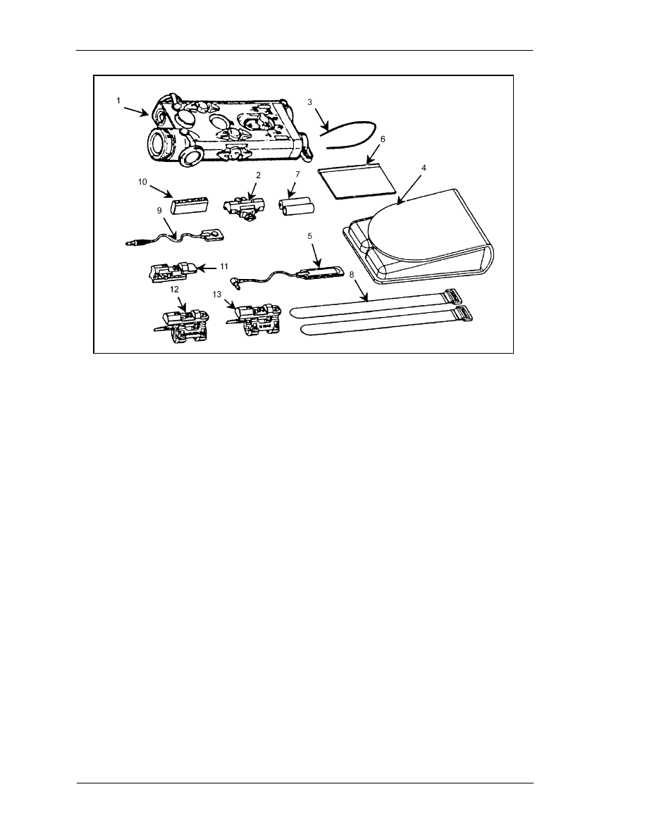
FM 3-23.25
(1) TPIAL
ASSEMBLY WITH SAFETY
(6)
O
PERATOR
’
S MANUAL
BLOCK
(7)
B
ATTERIES
1.5V AA
(2) R
AIL
(8)
S
TRAP
,
RETENTION
(3) N
ECK CORD
(9)
C
ABLE SWITCH
, 20-
INCH
,
BUTTON
(4) T
EXTILE BAG
(10)
B
RACKET ADAPTER
(5) C
ABLE SWITCH
, 12-
INCH
, (11)
T
RAINING EXTENDER
(A
RMY ONLY
)
MEMBRANE
(12)
M4/M16A2
BRACKET ASSEMBLY
Figure F-6. AN/PEQ-2A with accessories.
b.
Operation. This paragraph describes the battery installation, the safety block
installation, the mode switch, the button switch, the cable switch, the focus switch, the
lens cap, and the boresight adjusters.
(1)
Battery Installation (Figure F-7).
(a) Unscrew the battery caps and install two AA batteries.
(b) Orient the batteries as indicated by the markings on the AN/PEQ-2A body.
F-6
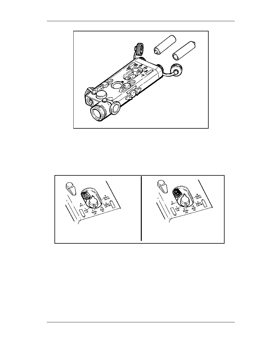
FM
3-23.25
Figure F-7. AN/PEQ-2A battery installation.
(2)
Safety Block Installation (Figure F-8). The safety block installed in the training
mode (blue side up) prevents the operator from accessing the noneye safe modes (AIM
HI, DUAL LO/HI, DUAL HI/HI). A .050 hex head Allen wrench is needed to unscrew
the block from the body and reinstall it in the tactical mode (black side up).
Figure F-8. Safety block installation.
(3)
Mode Selector. The mode selector is used to set the mode in which the
AN/PEQ-2A operates when the cable switch button or push button are depressed. The
mode selector has six positions (Table F-1).
F-7
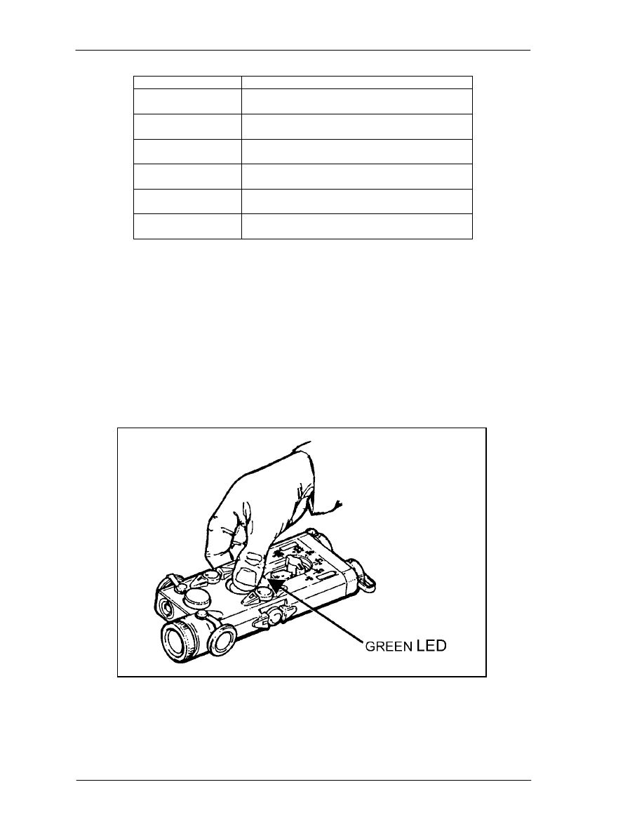
FM 3-23.25
KNOB POSITION
OPERATION
0
OFF
The AN/PEQ-2A will not operate.
1
AIM LO
The aiming beam operates at low power.
2
DUAL LO
The aiming beam operates at low power and
the illuminating beam operates at low power.
3
AIM HI
The aiming beam operates at high power.
4
DUAL LO/HI
The aiming beam operates at low power and
the illuminating beam operates at full power.
5
DUAL HI/HI
The aiming beam operates at high power and
the illuminating beam operates at full power.
Table F-1. Mode selector positions.
(4)
Button Switch (Figure F-9). The button switch is used when the AN/PEQ-2A is
hand held. Pressing the button switch operates the AN/PEQ-2A in the operational mode
set by the mode selector. When the button is released, the AN/PEQ-2A turns off.
(a) A green light emitting diode (LED) is incorporated into the body of the
AN/PEQ-2A to indicate that the AN/PEQ-2A is ON. Whenever the AN/PEQ-2A is
activated, the green LED will light and stay lit until the unit is turned OFF.
(b) If continuous operation of the AN/PEQ-2A is desired, pressing the button switch
twice in rapid succession will latch the AN/PEQ-2A ON. The AN/PEQ-2A will remain
on until the push button is pressed a third time.
Figure F-9. Operation of the button switch.
(5)
Cable Switch (Figure F-10). The cable switch is used when the AN/PEQ-2A is
mounted on a weapon. The cable switch plugs into the back of the AN/PEQ-2A
F-8
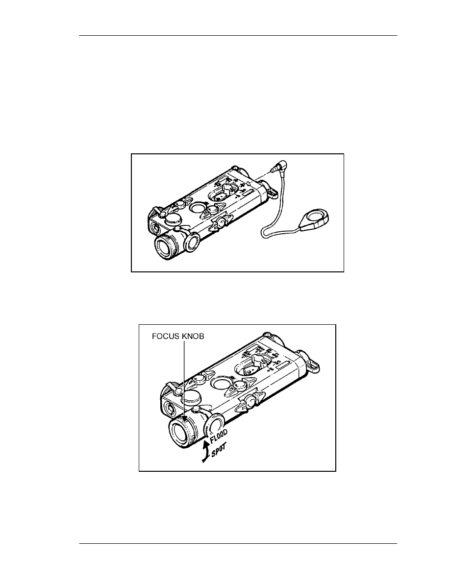
FM
3-23.25
assembly. Pressing the button or pad at the end of the cable switch causes the
AN/PEQ-2A to turn on in the operational mode selected by the mode select switch. When
the button is released, the AN/PEQ-2A turns off.
(a) If continuous operation of the AN/PEQ-2A is desired, pressing the cable switch
twice in rapid succession will latch the AN/PEQ-2A ON. The AN/PEQ-2A will remain
on until the push button is pressed a third time.
(b) When the cable switch plug is installed in the AN/PEQ-2A, it automatically locks
into place. To remove the switch, pull back on the plug sleeve and pull the plug out. DO
NOT TRY TO REMOVE THE PLUG BY PULLING ON THE CABLE.
Figure F-10. Installation of the cable switch.
(6)
Focus Knob (Figure F-11). The focus knob is used to vary the spread of the
illumination beam based on the range and size of the area to be illuminated.
Figure F-11. Using the focus knob.
F-9
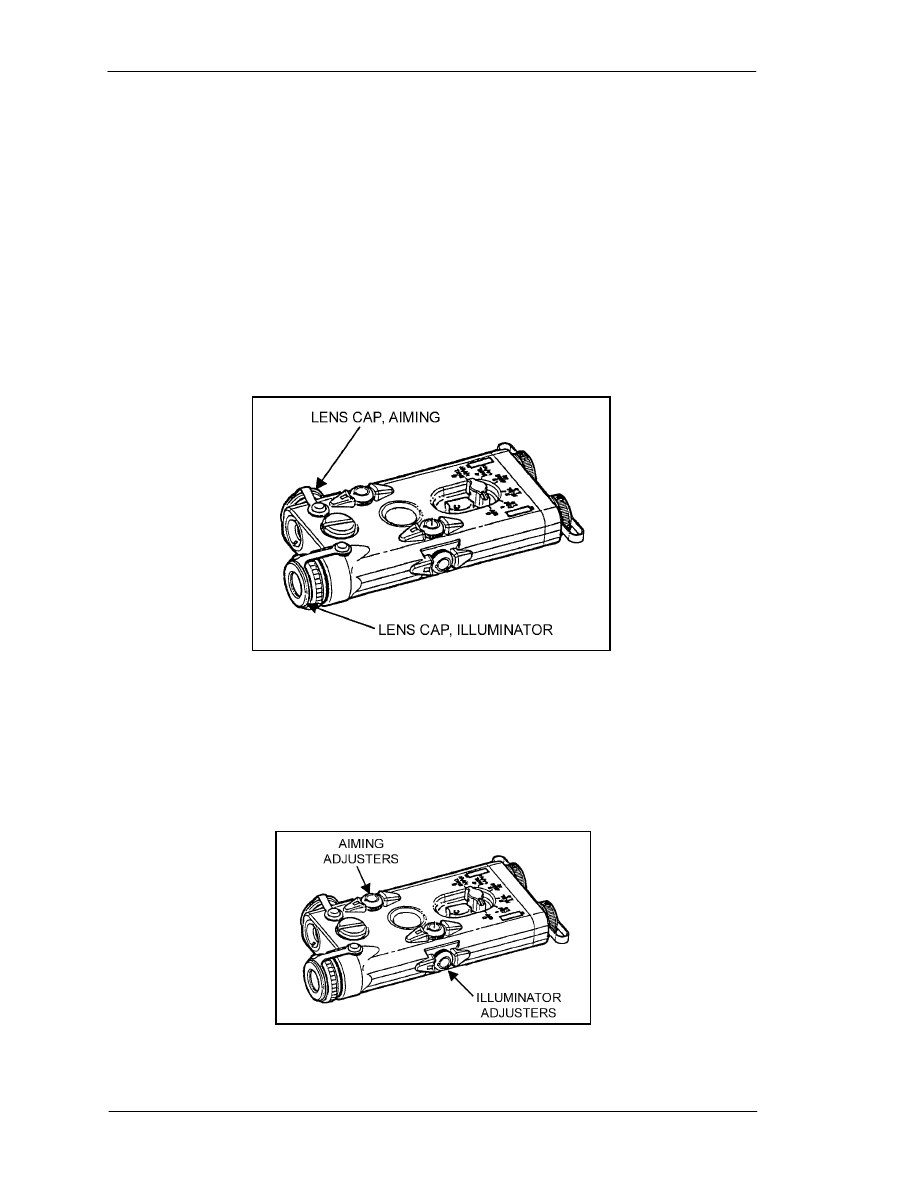
FM 3-23.25
(7)
Lens Cap (Figure F-12).
(a)
The
black lens cap blocks the AN/PEQ-2A illuminator or aiming laser beam
should the device be activated. To use the black lens cap, pull it from its stored location
on the side of the AN/PEQ-2A and stretch it over the front of the focus knob or aiming
beam so that it fits snugly in place.
(b)
The
diffuser lens cap enables the illuminator or aiming laser to emit in a
45-degree cone (10 feet at 10 feet). To use the diffuser lens cap, pull it from its stored
location on the side of the AN/PEQ-2A and stretch it over the front of the focus knob or
aiming beam so that it fits snugly in place.
(c)
The
neutral density lens cap enables the AN/PEQ-2A illuminator or aiming laser
to be operated in low power. To use the neutral density lens cap, pull it from its stored
location on the side of the AN/PEQ-2A and stretch it over the front of the focus knob or
aiming beam so that it fits snugly in place.
Figure F-12. Installing the lens caps.
(8)
Boresight Adjusters (Figure F-13). The AN/PEQ-2A is equipped with boresight
adjusters for zeroing the aiming beam and illumination beam. The AN/PEQ-2A adjusters
move the beams in true horizontal and vertical directions. When zeroing the
AN/PEQ-2A, it is best to zero the aiming beam to the weapon and then align the
illumination beam to the aiming beam.
Figure F-13. Boresight adjusters.
F-10
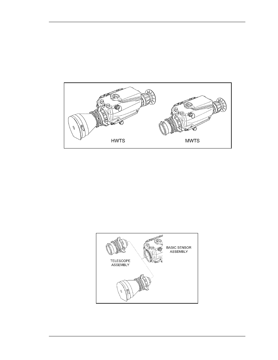
FM
3-23.25
F-3. AN/PAS-13 (V2) MEDIUM WEAPON THERMAL SIGHT and AN/PAS-13
(V3) HEAVY WEAPON THERMAL SIGHT
The AN/PAS-13 (V2) medium weapon thermal sight (MWTS) and the AN/PAS-13 (V3)
heavy weapon thermal sight (HWTS) (Figure F-14) are silent, lightweight, compact, and
durable battery-powered infrared imaging sensors that operate with low battery
consumption.
Figure F-14. HWTS and MWTS models of the thermal weapon sight.
a.
Description.
(1) Both the MWTS and the HWTS are referred to as singular thermal weapon sights
(TWS). The TWS is capable of target acquisition under conditions of limited visibility
such as darkness, smoke, fog, dust, and haze. The TWS operates effectively at night and
can also be used during the daytime. Infrared light is received through the telescope,
detected by an IR sensor, converted to digital data, processed, and then displayed for the
user. The TWS is composed of two functional groups: the telescope and the basic sensor.
(a)
Telescope. The telescope receives IR light emitting from an intended target and its
surroundings. The telescope magnifies and projects the IR light onto the scanner on the
basic sensor (Figure F-15).
Figure 3-6. TWS configurations.
F-11
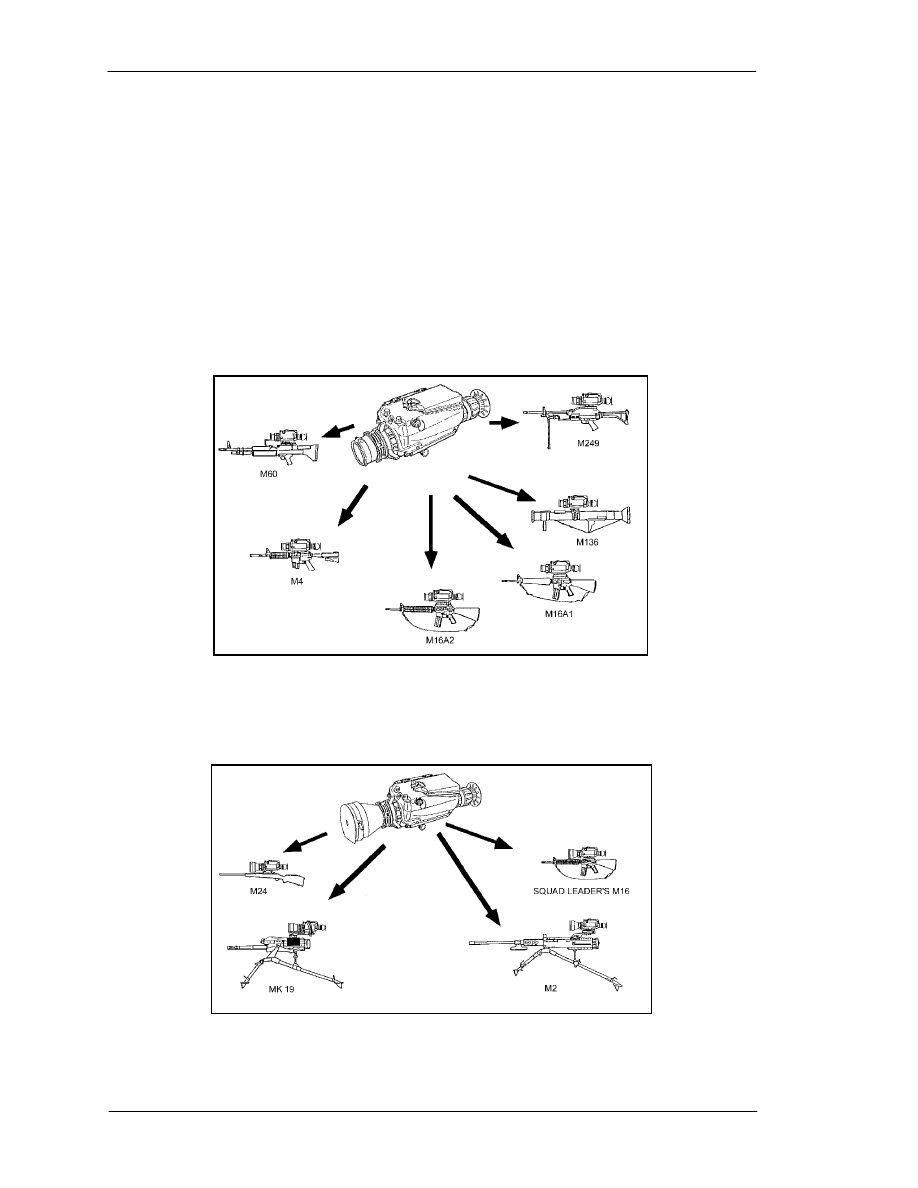
FM 3-23.25
(b)
Basic sensor. The scanner reflects the IR light received from the telescope onto
the detective assembly. The detective assembly senses the IR light and converts it to
video. The sensor’s electronics condition the video for display on the LED array. The
LED array illuminates the IR image along with the reticle. The light from the LED array
is reflected off the scanner to form an image at the eyepiece.
(2) The only difference between the MWTS and the HWTS are the telescopes, which
are different magnifications and hold different reticles. The basic sensor on the two
models is the same. The MWTS fits the M4 carbine, the M4 modular weapon system, the
M16A2, the M16A4 (not shown), the M249, the M60 machine gun, the M240B machine
gun (not shown), and the M136 grenade launcher (Figure F-16). The HWTS fits the
squad leader’s M16, the M24 sniper rifle, the M2, caliber .50 machine gun, and the
MK-19 grenade launcher (Figure F-17).
Figure F-16. MTWS.
Figure F-17. HTWS.
F-12

FM
3-23.25
b.
Technical Data.
MWTS
HWTS
Field of view (FOV):
Narrow
9
degrees
3
degrees
Wide
15
degrees
9
degrees
Telescope
magnification:
Narrow
FOV
3.3X
10X
Wide
FOV
2X
3.3X
Length:
15.5
inches
18
inches
Width:
6.25
inches
6.25
inches
Height:
6.25
inches
6.25
inches
Weight
4.1
pounds
4.5
pounds
Power
consumption:
ON
mode
12.0
watts
12.0
watts
STANDBY
mode
5.5
watts
5.5
watts
Battery
life:
71%
STANDBY
mode
10
hours
10
hours
EMERGENCY
mode
3.5
hours
3.5
hours
c.
Operation.
(1) The TWS has three modes of operation: STANDBY, ON, and EMERGENCY.
(a) STANDBY mode. When the system is first turned on, the TWS begins a cool
down period of approximately two minutes. After the cool down period, the TWS enters
the STANDBY mode. During the STANDBY mode, power is not applied to the scanner
or display in order to extend the life of the battery.
(b) ON mode. When the TWS is in the STANDBY mode and pressure is applied to
the eyecup, the TWS switches to the ON mode, and a switch engages to provide power to
the scanner and display. After a three-second delay, the system is fully operational.
(c) EMERGENCY mode. When switched to the EMERGENCY mode, the TWS
continuously applies power to the entire system. This allows the operator to bypass the
three-second delay experienced when switching from the STANDBY to the ON mode.
Since power is applied to the entire system while in the emergency mode, battery life is
greatly reduced.
(2) Controls and indicators are as shown in Figure 3-18.
(a) The BRIGHTNESS CONTROL is a nine-position rotary switch with an off detent
position (turned fully counterclockwise). The purpose is to turn the system on or off and
adjust the brightness of the eyepiece display.
(b) The CONTRAST CONTROL adjusts the contrast of the thermal image displayed
on the raster. It has an automatic and a manual mode.
(c) The FOCUS RING adjusts the telescope focus from 20 meters to infinity. It
requires a manual adjustment and affects both the wide and narrow fields of view.
(d) The FIELD OF VIEW RING is located on the telescope. It has a wide and a
narrow field of view. The wide FOV is for using low magnification during target
detection, and the narrow FOV is for using high magnification during recognition and
engagement.
(e) The RETICLE SELECT SWITCH selects one of the available reticles depending
on the TWS model (medium or heavy). It must be held for two seconds to enable reticle
F-13
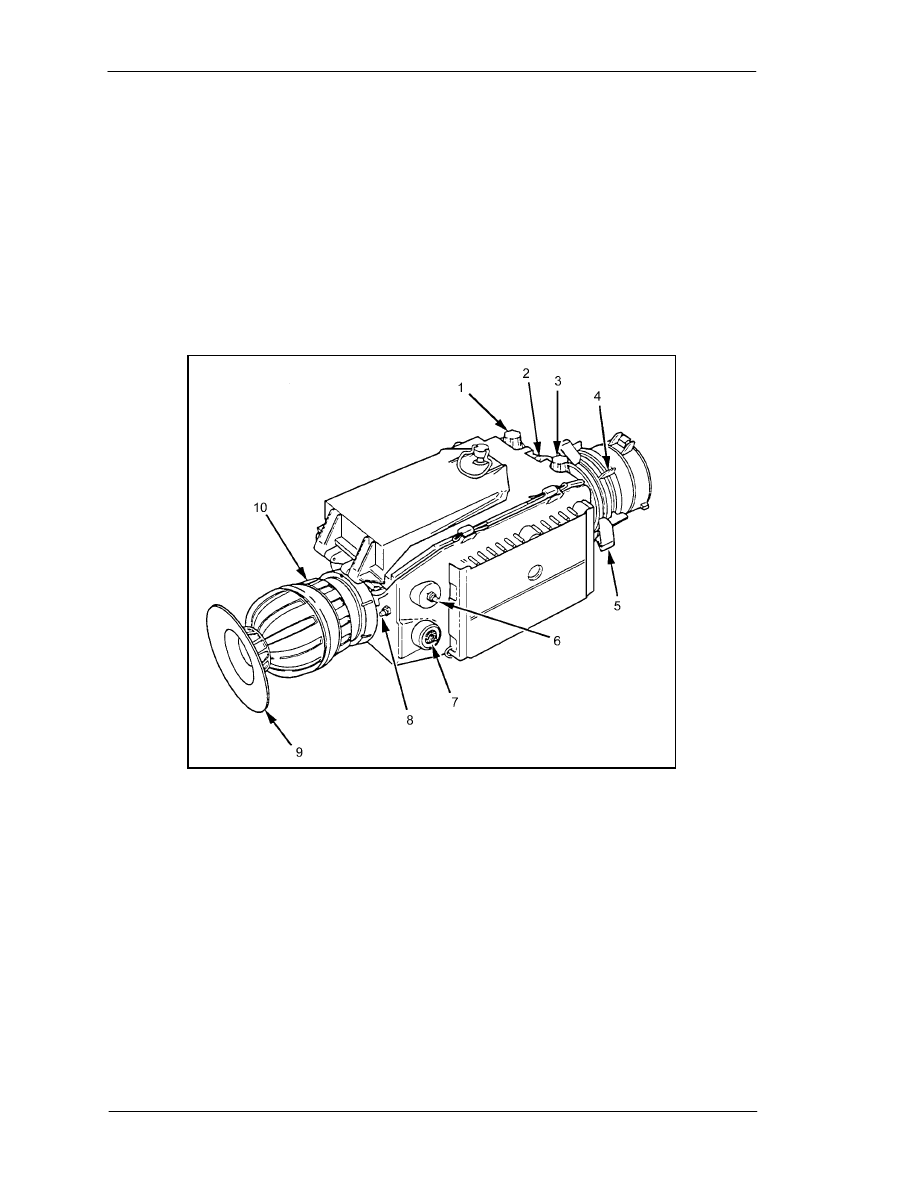
FM 3-23.25
changes. After two seconds, release the switch to cycle to the next reticle. This control is
disabled after ten seconds of inactivity.
(f) The RETICLE ADJUST SWITCH adjusts the reticle aiming features in azimuth
and elevation. It is used during zeroing, and it must be held for two seconds to allow
changes to be made. After two seconds, each press moves the reticle aiming features one
increment. This control is also disabled after ten seconds of inactivity.
(g) The BLACK/WHITE POLARITY SWITCH selects the polarity of the thermal
image displayed on the raster. The initial setting is “white hot.” The polarity switch
affects the appearance of the target.
(h) The DIOPTER FOCUS RING adjusts the focus of the raster and indicators to the
operator’s eye. It ranges from +2 to -6 diopters.
(1) B
RIGHTNESS CONTROL
(6)
R
ETICLE SELECT SWITCH
(2) E
MERGENCY SWITCH CONTROL
(7) R
ETICLE ADJUST SWITCH
(3) C
ONTRAST CONTROL
(8)
B
LACK
/
WHITE POLARITY SWITCH
(4) F
OCUS RING
(9)
E
YECUP
(5) F
IELD OF VIEW RING
(10)
D
IOPTER FOCUS RING
Figure F-18. TWS controls and indicators.
(i) The EYEPIECE INDICATORS (Figure F-19) illuminate as follows:
•
NOT COOL when the detectors are not cool enough for proper operation.
•
WHT HOT/BLK HOT polarity.
•
EMER during emergency mode operation.
•
LOW when battery power has approximately fifteen minutes of useful power
left.
F-14
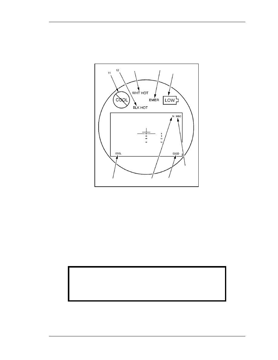
FM
3-23.25
(j)
The
COOLDOWN
PERIOD INDICATORS blink the first ten seconds after the
system is turned on. After ten seconds, the NOT COOL indicator is lit and the
POLARITY, EMERGENCY, and LOW BATTERY indicators function normally.
(k) The DISPLAY RASTER displays the thermal image with a superimposed reticle.
Figure F-19. Eyepiece indicators.
F-4. M136 AT4/M287 AT4 SUBCALIBER TRACER TRAINER SIGHT
ALIGNMENT PROCEDURES
The fundamentals of marksmanship are the same as during the daytime with two
exceptions. When using aided vision devices, the firer should hold the mounting bracket
with the left hand. This method provides greater stability and helps to balance the AT4
against the added weight of the sight. When aiming the AT4, remember to aim by placing
the infrared aiming light center mass on the target.
WARNING
When firing the M136 AT4, do not place your face within
3 inches of the mounted sight. The recoil of the AT4
could cause injury you or damage to the equipment.
a.
Select
a
stable
position for the weapon.
F-15

FM 3-23.25
b. Open the M136 front and rear sight covers. During limited visibility conditions,
the 7-millimeter peephole may be necessary for zeroing.
c. Set the rear sight for 200 meters and choose the appropriate scenario.
(1) Place a 25 meter zero target with a predetermined offset at 10 meters and align the
weapon’s fixed sight to coincide with the 4-centimeter aiming point of the zero target.
(2) Select a suitable target at 200 meters and align the weapon’s fixed sight center
mass of the target.
d. Turn on the infrared aiming light. Use the AN/PVS-7B or AN/PVS-14 to observe
the infrared aiming light (without moving the weapon).
e. Adjust the infrared aiming light so that it coincides with the 2-centimeter offset
aiming point of the 25-meter zero target. If the 200-meter method is used, adjust the
aiming point of the mounted sight to coincide center mass on the 200-meter target.
f. Repeat the procedure until the aiming light is sight aligned to the weapon by
adjusting the controls on the AN/PAQ-4C.
NOTE: Use the same procedures to conduct sight alignment of the AN/PEQ-2.
g. Conduct a preventive maintenance inspection before the instructional and
qualification tables are fired. Once the soldiers have completed Tables I and III (day
tables), they receive additional instruction on the use of aided vision devices for night
operations.
(1)
Table I (Instructional Day). This scenario consists of 12 targets from 100 to
300 meters. The standard to proceed to the next table is 6 out of 12 targets successfully
engaged.
(2)
Table II (Instructional Night). This scenario consists of 12 targets from 100 to
300 meters. The standard to proceed to the next table is 6 out of 12 targets successfully
engaged at night.
(3)
Table III (Qualification Day). This scenario consists of 10 targets from 100 to
300 meters. The standard to proceed to the next table is 8 out of 10 targets successfully
engaged.
(4)
Table IV (Qualification Night). This scenario consists of 10 targets from 100 to
300 meters. The standard to proceed to the next table is 6 out of 10 targets successfully
engaged.
h. The night sustainment training strategy should be conducted over a one-day time
frame and consists of the following:
(1)
Night Vision Goggles Familiarization Training. Soldiers receive instruction on
the proper use and fit of night vision goggles, to include characteristics and capabilities,
maintenance, and mounting procedures.
(2)
Infrared Aiming Light Familiarization Training. Soldiers boresight the weapon
and aided vision device at a range of 10 meters.
(3)
Fundamentals of Firing (Body Position with Head Harness and NVD, Foxhole
and Prone). Soldiers review and practice firing positions and fundamentals of
marksmanship and any changes that may occur by use of the infrared aiming device.
(4) Weapon and Equipment Precombat Inspection. The weapon and infrared aiming
device is inspected and properly mounted. Inspect to ensure that the infrared aiming
F-16

FM
3-23.25
device is mounted securely to the mount and that the mount is tightly secured to the
weapon. A review of clearing or misfire procedures is important.
(5) Infrared Aiming Light Boresight to Weapon. Each soldier boresights the weapon
and infrared aiming device at a range of 10 meters. If a bore light is not available, then
zero the weapon and sight by using the specified zeroing procedure for that weapon/sight
combination.
F-17

FM 3-23.25
Glossary-1
GLOSSARY
AC
Active Component
ANCOC
advanced noncommissioned officer course
AN/PVS
Army Navy passive vision sight
ARTEP
Army Training and Evaluation Program
backblast
The backward blast created by igniting the propellant in a weapon
designed to be as recoilless as possible.
blast
An explosive or violent detonation that produces a direct effect on its
target in addition to radiant heat and overpressure at its point of origin.
BMP
a type of non-US fighting vehicle built by the former Soviet Union
BNCOC
basic noncommissioned officer course
BRDM
a type of non-US scout car built by the former Soviet Union
BTR
a type of non-US personnel carrier built by the former Soviet Union
C
Centigrade
CS
combat support
CSS
combat service support
DA
Department of the Army
DKIE
decontamination kit individual equipment
DOD
Department of Defense
DS
direct support
F
Fahrenheit
FHT
field handling trainer

FM 3-23.25
Glossary-2
fps
feet per second
FTX
field training exercise
HE
high-explosive
HEAT
high-explosive antitank
HELLFIRE
heliborne laser fire and forget (a missile system)
HMTS
medium weapon thermal sight
HWTS
heavy weapon thermal sight
IAW
in accordance with
IET
initial entry training
IR
infrared
kmph
kilometers per hour
LAW
light antitank weapon
LED
light emitting diode
METL
mission-essential task list
MILES
Multiple Integrated Laser Engagement System
mm
millimeter(s)
MMTT
manned moving target tank
MOPP
mission-oriented protective posture
MOUT
military operations on urbanized terrain
mph
miles per hour
mps
meters per second
MTP
mission training plan

FM 3-23.25
Glossary-3
MWTS
medium weapon thermal sight
NA
not applicable
NATO
North Atlantic Treaty Organization
NBC
nuclear, biological, chemical
NCO
noncommissioned officer
NSN
national stock number
NVD
night vision device
OIC
officer in charge
overpressure
increased atmospheric pressure (positive overpressure), followed by a
wave of decreased atmospheric pressure (negative overpressure),
produced around the origin of an explosive or violent detonation
PLDC
primary leadership development course
POI
program of instruction
promethium
a radioactive metallic element of the rare-earth group used to
illuminate range markings on the front sight of the M72-series LAW
RC
Reserve Component
RPG
rocket-propelled grenade (non-US)
STX
situational training exercise
SMCT
soldier's manual of common tasks
SOP
standing operating procedure
spall
small fragment or chip
STP
soldier training publication

FM 3-23.25
Glossary-4
STRAC
standards in training commission
TOC
tactical operations center
TP
training-practice
TPIAL
target pointer/illuminator/aiming light, AN/PEQ-2A
TRADOC
(US Army) Training and Doctrine Command
trc
track (as used in STRAC manual)
TRP
target reference point
TSC
training support center
TWS
thermal weapon sight

FM 3-23.25
iii
PREFACE
This manual provides technical information, training techniques, and combat
techniques of light antiarmor weapons. Intended users include leaders and designated
soldiers who will use this information to successfully integrate light antiarmor weapons
into combat operations. This manual discusses gunnery training and train-the-trainer.
The tactical positions shown in this manual were drawn to enhance the reader's
understanding of related subject material and do not necessarily represent the best
employment option for that material.
Unless this publication states otherwise, masculine nouns and pronouns do not refer
exclusively to men.
The proponent of this publication is the United States Army Infantry School. Send
comments and recommendations on DA
Form
2028 (Recommended Changes to
Publications and Blank Forms) directly to―
Commandant
US Army Infantry School
ATTN: ATSH-IN-S3
Fort Benning, GA 31905-5595
lusanoh@benning.army.mil

FM 3-23.25
Index-1
INDEX
adjustment of fire, 2-11, 3-7, 3-8 (illus), 6-10
adjustment of sights
M72-series LAW, 2-8, 2-9 (illus)
M136 AT4, 3-7, 3-8 (illus)
aiming procedures, 2-11, 4-2 to 4-6 (illus)
ambushes, antiarmor, 6-13, 6-14 (illus)
AN/PVS-4 nightsight, 2-9 to 2-12 (illus), 6-10
arming range, minimum, 2-2, 3-2, A-4
armored vehicle
dead space, 6-4 (illus)
weaknesses, 6-2, 6-3 (illus)
armor-killer teams, 6-13
assistant trainers, B-12
AT4 (see M136 AT4)
backblast, 2-1, 2-13, 3-8, 3-11 to 3-13 (illus), 5-2 to 5-6 (illus), 6-10, 6-11, A-1 to A-3
(illus), B-1, B-6, D-1 (illus)
buildings
engaging, 6-8, 6-9 (illus)
firing from, 6-10
bunkers, engagement of, 6-9 (illus)
care and handling, 1-2, 2-5, 3-4
collective training, 7-1, 7-4
color codes, M136 AT4, 3-4 (illus)

FM 3-23.25
Index-2
combat
range, minimum, 2-2, 3-2, A-4
techniques, 6-1
DA Form 7323-R (M72-Series LAW Scorecard), E-1, E-2 (illus)
DA Form 7324-R (M136 AT4 Scorecard), E-4, E-5 to E-6 (illus)
danger zones, A-1, A-2
dead space, armored vehicle, 6-3, 6-4 (illus)
defensive operations, 6-12, 6-14
effective range, maximum, 2-2, 3-2, 6-12, D-2
effects, weapon, 2-3, 3-2, 3-3 (illus), 6-9 (illus), 6-11
employment, 1-1, 2-3, 6-1, 6-4, 6-10 to 6-14 (illus)
enclosures, firing from, 6-11, A-2, A-3
engagement range, 2-2, 3-2
maximum, D-2
minimum, A-4
eye placement, 4-2 (illus)
field fortifications, engagement of, 6-9 (illus)
field-handling trainers, C-1 to C-5, C-7 M72-series LAW, B-1 (illus), B-2 (illus)
M136 AT4, 3-4, 3-12, 4-6, B-6
firing
from enclosures, 6-11, A-2, A-3
limitations, A-2, A-3, A-4
line, D-1
positions (see appropriate weapon)
range, suggested design for, D-1
tables, 7-2, E-3, E-7, E-8
techniques, 6-9 (illus)
force-on-force trainer, 7-4

FM 3-23.25
Index-3
fratricide avoidance, 1-2, 1-3, 2-5, 2-11, 2-13, 2-14, 3-11, 6-12, A-1 to A-4
front sight template, B-5 (illus)
fundamentals of marksmanship, 4-2 to 4-6 (illus)
Graphic Training Aid 7-2-5 (Sight Engagement Trainer, AT4), B-5 (illus)
gunnery training requirements, 7-1 to 7-3
IET (initial entry training), 7-1, 7-2
illumination, 6-10, E-3, E-7, E-8
individual training, 7-1 to 7-5
infantry fighting position, A-3
initial entry training (IET), 7-1 7-2
inspection
M72-series LAW, 2-5
M136 AT4, 3-4
institutional training, 7-1 (illus)
kills, types of, 6-5
launcher, expended
M72-series LAW, B-1 (illus), B-2 (illus)
M136 AT4, B-6
LAW (light antitank weapon
see M72-series LAW)
limited visibility, 3-1, 6-1, 6-10, 6-13
armored vehicle, 6-3, 6-4 (illus)
firing tables, E-1, E-3, E-7, E-8
live fire, 1-2 (illus), 1-3, 2-15, 3-12, 3-13, 6-10, 7-2, B-1, B-10

FM 3-23.25
Index-4
M72A1 mounting bracket assembly, 2-10
M72-series LAW, 1-1 (illus), 2-1, 2-2 (illus), 2-12, 4-6
employment, 1-1, 2-3, 4-3, 4-4 (illus), 6-1, 6-4, 6-10 to 6-14 (illus)
firing
mechanism, 2-6 to 2-8 (illus)
positions, 5-1 to 5-6 (illus)
range, suggested design for, D-1
tables, 7-2, E-3
misfire procedures, 1-2, 1-3, 2-14, 7-3, 7-5, C-6
nightsight, 2-10
operation and function, 2-12
packaging, 2-4 (illus)
rocket, 2-2, 2-3 (illus)
safety, 2-5, 2-8, 2-11, 2-14, 2-15, A-2 (see also backblast and fratricide avoidance)
safety mechanism, 2-6 (illus), 2-7 (illus)
scorecard, E-1, E-2 (illus)
sight
adjustment, 2-8, 2-9 (illus)
picture, 4-3 to 4-5 (illus)
target engagement, 4-3 (illus), 4-4 (illus)
technical data, 2-2
training device, B-1, B-2 (illus)
warhead, 2-3
weapon effects, 2-3, 5-6, 6-8, 6-9 (illus)
M72-Series LAW Scorecard (DA Form 7323-R), E-1, E-2 (illus)
M136 AT4, 3-1 (illus)
employment, 1-1, 4-4, 4-5 (illus), 6-1, 6-4, 6-10 to 6-14 (illus)
firing
mechanism, 3-5 (illus)
positions, 5-1 to 5-6 (illus), A-2
range, suggested design for, D-1
tables, 7-2, E-7
function, 3-5
misfire procedures, 1-2, 1-3, 3-11 to 3-13 (illus), 7-3, 7-5, C-6
operation, 3-1, 3-8 to 3-11 (illus), 4-6, 6-11 (illus)
overpressure, 6-10
packaging, 3-3 (illus)
safety, 3-8, 3-12, 6-10, A-2 to A-3 (see also backblast and fratricide avoidance)
safety mechanisms, 3-5 (illus), 3-6 (illus)
scorecard, E-4, E-5 to E-6 (illus)
sight
adjustment, 3-7, 3-8 (illus), 3-10 (illus)
picture, 4-4 to 4-5 (illus)

FM 3-23.25
Index-5
target engagement, 4-4, 4-5 (illus)
technical data, 3-2
training devices, 3-4 (illus), B-6 (illus)
warhead, 1-3, 3-2, A-4
weapon effects, 3-2, 3-3 (illus), 5-6,
6-8, 6-9 (illus)
M136 AT4 Scorecard (DA Form 7324-R), E-4, E-5 to E-6 (illus)
M190 subcaliber launcher, 2-15, B-1 to B-5, E-2
M287 subcaliber tracer trainer, 3-13, B-6 (illus), B-12, E-7 to E-8
marksmanship, fundamentals of, 4-2 through 4-6 (illus)
maximum effective range, 2-2, 3-2, 6-12, D-2
maximum engagement range, 2-2, 3-2, D-2
methods of engagement, 6-5 to 6-7
METL (mission-essential task list), 7-4
MILES (multiple integrated laser-engagement system), 7-4 (illus)
minimum range, 2-2, 3-2, A-4
misfire procedures, 1-2, 1-3, 7-3, 7-5, C-6
M72-series LAW, 2-14
M136 AT4, 3-11 to 3-13 (illus)
M190 subcaliber launcher, 2-15, B-5
M287 9-mm subcaliber tracer trainer, 3-13, B-12
mission-essential task list (METL), 7-4
mission outlines, 7-4
multiple integrated laser-engagement system (MILES), 7-4 (illus)
NBC (nuclear, biological, chemical), 6-10
nightsight (AN/PVS-4), 2-9 to 2-12 (illus), 6-10
NVDs (night vision devices), 2-9 to 2-12 (illus), 6-10

FM 3-23.25
Index-6
obstacles, 6-3, 6-13
offensive operations, 6-1, 6-12
operating temperatures, 1-3, 2-1, 2-5 (illus), A-1, A-4, B-8
operations
defensive, 6-12, 6-14
offensive, 6-1, 6-12
overhead fire, A-4
overpressure, 6-10
performance evaluations, C-1
POIs (programs of instruction), 7-1 (illus)
raids, 6-14
range
card, 6-12
design, D-1
estimation, 6-1
of fire, 2-2, 3-2, A-4
safety, 2-14, A-3, B-5, B-12
reactive armor, 6-2, 6-3
rear area operations, 6-13
resources, 7-3, B-1
restrictive terrain, 6-13
roles of light antiarmor weapons, 6-12 to 6-14
safety, 2-14, A-2 (see also backblast and fratricide avoidance)
decontamination procedures, 1-3
destruction procedures, 1-2 firing from an enclosure (combat), 6-11, A-2,
A-3 limitations, A-2
hearing protection, 3-8, 6-11, A-3
infantry fighting position, A-2, A-3

FM 3-23.25
Index-7
M72-series LAW, 2-5, 2-8, 2-11, 2-14
M136 AT4, 3-8, 3-11, 3-12
M190 subcaliber launcher, 2-15, B-5
M287 9-mm subcaliber tracer trainer, 3-13, B-10, B-12
nightsight, 2-11
range safety, 2-14, B-5, B-12
training, A-1, B-1
scorecards, example completed
M72-series LAW, E-2 (illus)
M136 AT4, E-5 to E-6 (illus)
sector sketch, 6-1, 6-12
security teams, 6-13
sight alignment, 4-2 to 4-5 (illus), 4-6
sight engagement trainer, AT4, B-5 (illus)
sights
M72-series LAW, 2-8, 2-9 (illus)
M136 AT4, 3-7 (illus), 3-8 (illus), 3-10 (illus)
skill retention, 7-2 (illus), 7-5
speed estimation, 6-1, 6-2 (illus)
stationary targets, 4-3 to 4-5 (illus)
STRAC (Standards in Training Commission), 7-2, 7-3 (illus)
sustainment training program, 7-2 (illus), 7-5
tactical employment, 1-1, 2-3, 6-1, 6-4, 6-10 to 6-14 (illus)
target array, D-2 (illus)
target engagement, 4-3 to 4-5 (illus), 6-1
target silhouette sheet, B-5 (illus)
targets, moving, 4-3 to 4-5 (illus), 6-2, 6-7 (illus)

FM 3-23.25
Index-8
technical data
M72-series LAW, 2-2
M136 AT4, 3-2
techniques of fire, 6-1, 6-2 (illus)
temperature effects, 1-3, 2-5, A-4, B-2
terrain, restrictive, 6-13
tracer trainer, subcaliber (M287), 3-13, B-6, B-12
training, 7-1 (illus), B-1
aid, graphic, B-5 (illus)
collective, 7-1, 7-4
exercises, 7-2, B-1
facilities, D-1
frequency, 7-3 (illus)
individual, 7-1 to 7-5
initial entry, 7-1
institutional, 7-1 (illus)
program, 7-1
requirements, 7-2, 7-3 (illus)
safety, 2-14, A-1
sequence, 7-4
strategy, 7-1
unit, 7-2
training devices
expended launchers, 1-3, 4-6, B-1, B-2 (illus), B-6, C-1, E-3
field-handling trainers, 3-4, 3-12, 4-6, B-6
force-on-force trainers, 7-4
subcaliber trainers, 3-13, 6-10, B-1, B-6
Training Support Center (TSC), B-1
train-the-trainer, 7-4
TSC (Training Support Center), B-1
unit training, 7-2
Viper, 7-4

FM 3-23.25
Index-9
warhead (see appropriate weapon)
weapon effects, 6-2
M72-series LAW, 2-3
M136 AT4, 3-2 to 3-3 (illus)
weather conditions, 1-3, 2-5, A-4, B-2 (see also limited visibility)
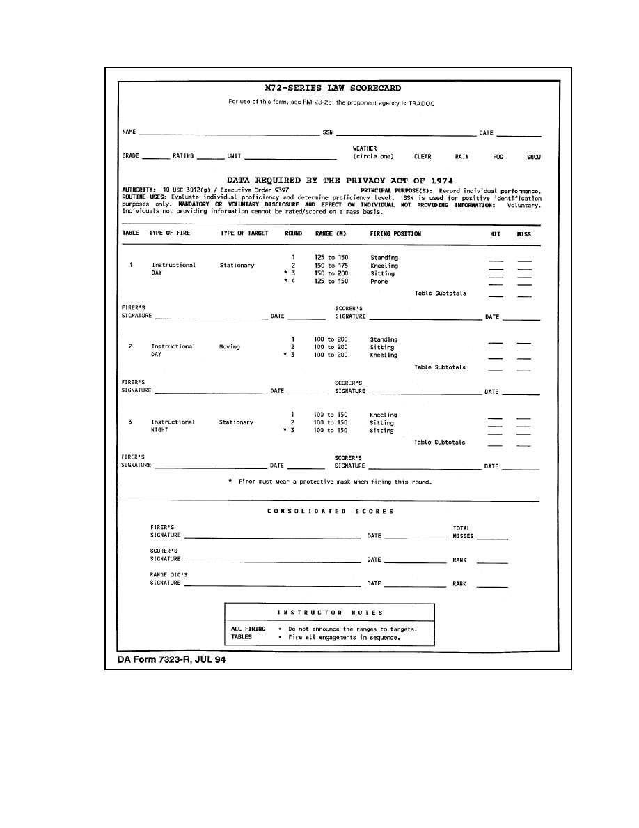
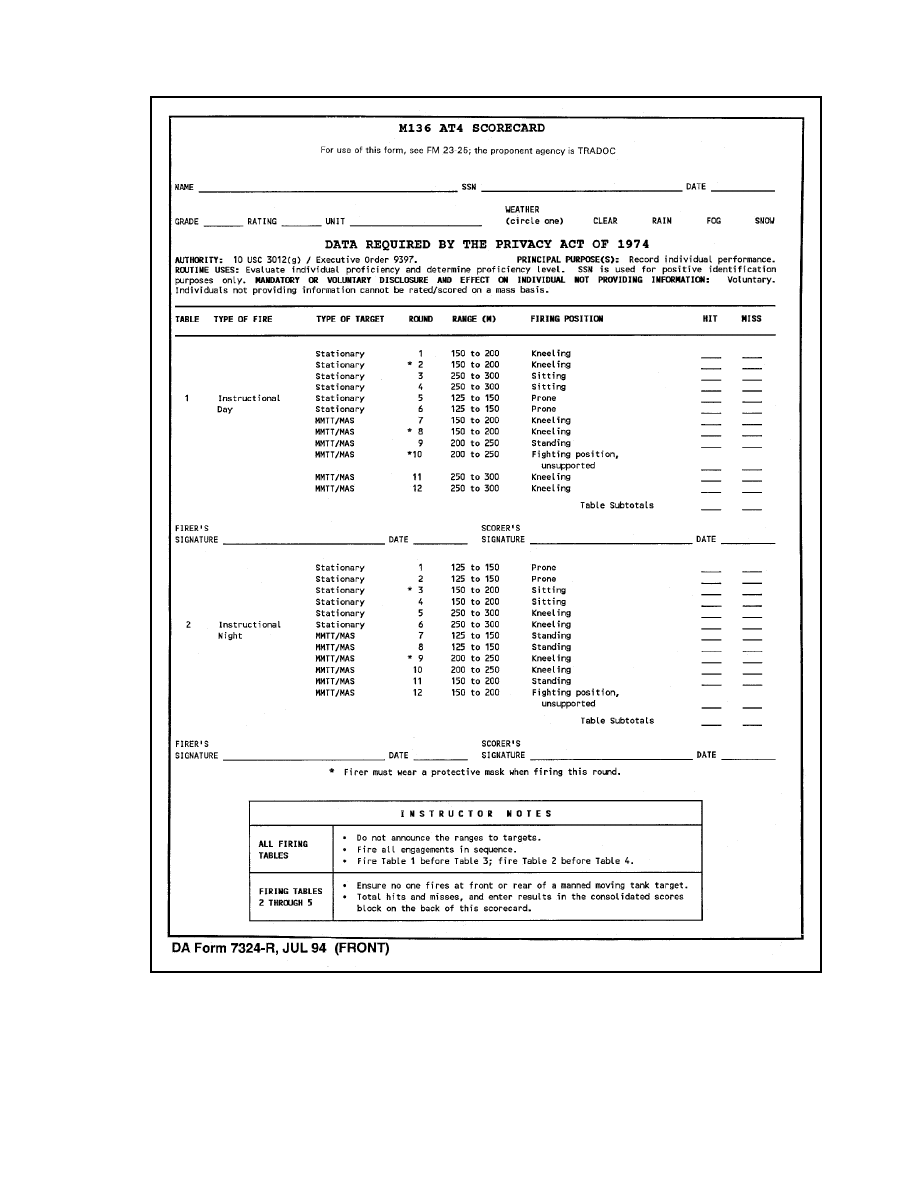
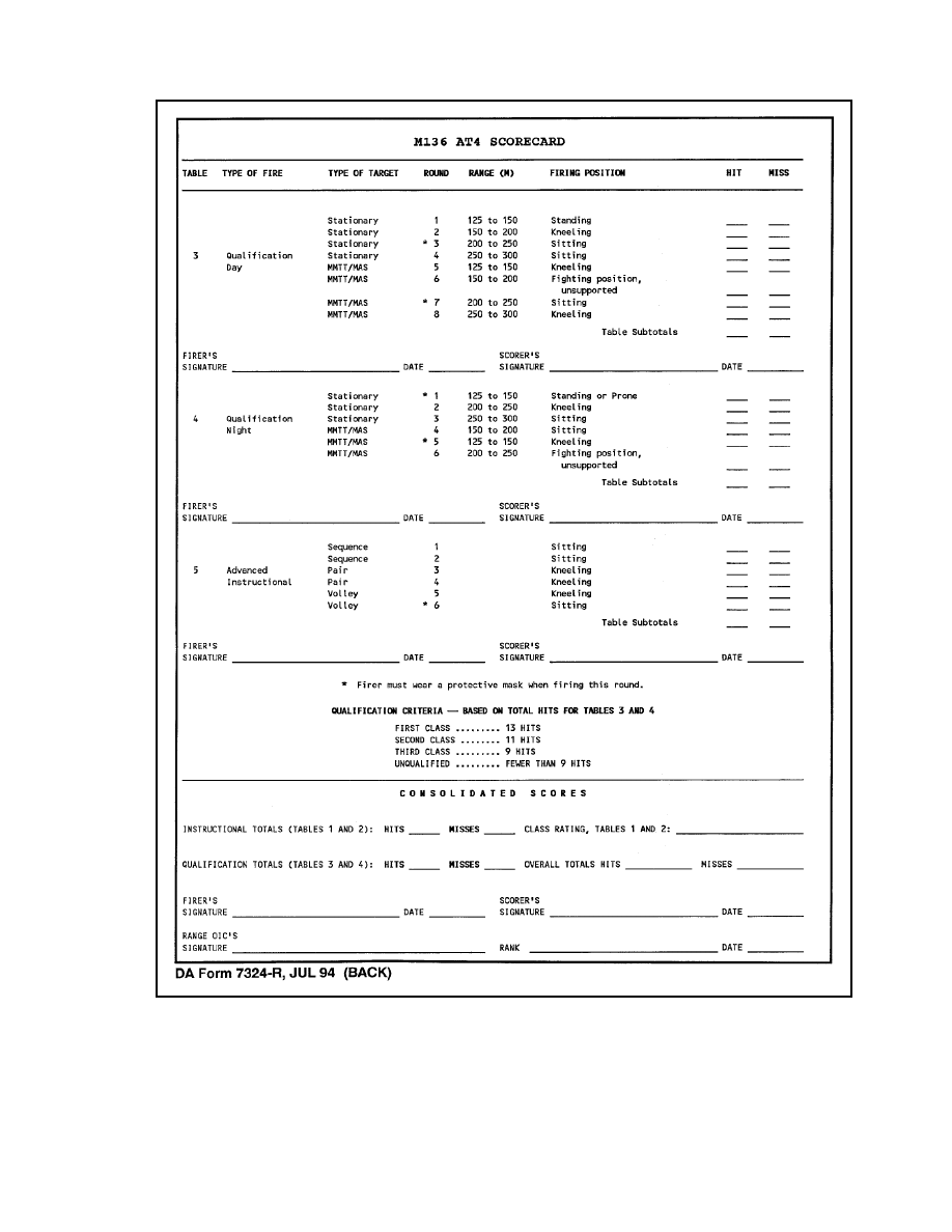

FM 3-23.25
References-1
REFERENCES
SOURCES USED
These are the sources quoted or paraphrased in this manual.
TM 9-1055-886-12&P
Operator and Unit Maintenance Manual for M287 9-MM
Tracer Bullet Training Device. 25 October 1989.
TM 9-1315-886-12
Operator's and Unit Maintenance Manual for Launcher
and Cartridge, 84
Millimeter: M136 (AT4).
15 May 1990.
TM 9-1340-214-10
Operator's Manual for 66-MM Light Antitank Weapon
(LAW) System M72A1, M72A2 with Coupler, M72A3,
and Practice Rocket Launcher M190 with M73 Practice
Rocket. 20 February 1992.
TM 11-5855-213-10
Operator's Manual for Night Vision Sight, Individual-
Served Weapon AN/PVS-4. 1 February 1993.
TM 11-5855-213-23&P
Unit and Direct Support Maintenance Manual for Night
Vision Sight, Individual-Served Weapon, AN/PVS-4.
1 June 1993.
DOCUMENTS NEEDED
These documents must be available to the intended users of this publication.
DA Form 7323-R
M72-Series LAW Scorecard. July 1994.
DA Form 7324-R
M136 AT4 Scorecard. July 1994.
DA Pamphlet 350-38
Standards in Weapons Training. 3 July 1997.
*DOD
5100.76-M
Physical Security of Sensitive Conventional Arms,
Ammunition, and Explosives. 3 February 1983.
FM 7-7
The Mechanized Infantry Platoon and Squad (APC).
15 March 1985.
FM 7-7J
The Mechanized Infantry Platoon and Squad (Bradley).
7 May 1993.
FM 7-8
The Infantry Platoon and Squad. 1 March 2001.
FM 25-101
Battle Focused Training. 30 September 1990.

FM 3-23.25
References-2
GTA 7-2-5
Sight Engagement Trainer, AT4 (Parts 1 and 2).
2 January 1990.
GTA 17-2-13
Armored Vehicle Recognition. 1 May 1987.
STP 7-11BCHM1-SM-TG
Soldier’s Manual and Trainer’s Guide, Skill Level 1,
CMF11, Infantry. 19 June 2000.
STP 7-11BCHM14-SM-TG
Soldier's Manual and Trainer's Guide, Skill Level 2/3/4,
MOS 11B, 11C, 11H, and 11M, Skill Levels 1/2/3/4.
19 June 2000.
STP 21-1-SMCT
Soldier's Manual of Common Tasks, Skill Level 1.
1 October 1994.
TC 90-1
Training for Military Operations on Urbanized Terrain.
30 September 1993.
READINGS RECOMMENDED
These readings contain relevant supplemental information.
AR 190-11
Physical Security of Arms, Ammunition, and Explosives.
30 September 1993.
AR 385-63
Policies and Procedures for Firing Ammunition for
Training, Target Practice, and Combat. 15 October 1983.
FM 3-5
NBC Decontamination. 28 July 2000.
FM 5-250
Explosives and Demolitions. 30 June 1998.
FM 20-3
Camouflage, Concealment, and Decoys. 30 August 1999.
FM 90-5 (HTF)
Jungle Operations (How to Fight). 16 August 1982.
FM 90-10-1
An Infantryman's Guide to Combat in Built-Up Areas.
3 October 1995.
Document Outline
- toc.pdf
- ch2.pdf
- ch5.pdf
- ch6.pdf
- ch7.pdf
- appb.pdf
- appc.pdf
- appd.pdf
- appe.pdf
- appf.pdf
- bib.pdf
Wyszukiwarka
Podobne podstrony:
4 Steyr Operation and Maintenance Manual 8th edition Feb 08
Bank Operations and Management Nieznany (2)
Microphones Methods of Operation and Type Examples Gerhart Boré, Stephan Peus
Actuators and Sensors Stepper Motors Stepper Motor Operation and Theory
5 Operation and maintenance manual Alamarin jet Ver 1
4 Steyr Operation and Maintenance Manual 8th edition Feb 08
OPERATORS AND THINGS THE INNER LIFE OF A SCHIZOPHRENIC
5 Operation and maintenance manual Alamarin jet Ver 1
Different Worlds Unacknowledged Special Operations and Covert Action
Computer Virus Operation and New Directions
Firearms ARMBRUST Anti tank Weapon Plans from Kurt Saxon Upped by Zaibatsu
Computer Virus Operation and New Directions 1997
L 3 Complex functions and Polynomials
Functional Origins of Religious Concepts Ontological and Strategic Selection in Evolved Minds
Verb form and function
Euler’s function and Euler
więcej podobnych podstron