
CORRELATION BETWEEN HEAT-CHECKING
RESISTANCE AND IMPACT BENDING ENERGY
OF HOT-WORK TOOL STEEL DIN 1.2344.
J. Buckstegge
Edelstahl Witten-Krefeld GMBH
Testing Department
P.O.B. 10 06 46
D-47706 Krefeld
Germany
B. Gehricke
Edelstahl Witten-Krefeld GMBH
Research and Development, Customer Service
Tool Steel
D 58452 Witten
Germany
U. Reichel
Edelstahl Witten-Krefeld GMBH
Testing Department
P.O.B. 10 06 46
D-47706 Krefeld
Germany
Abstract
The permanently increasing production of die cast aluminium and magnesium
parts is directly related to an increasing demand in premium hot-work tool
steels for die casting dies.
861

862
6TH INTERNATIONAL TOOLING CONFERENCE
One of the major failure modes of the die casting tools is the occurrence
of heat checking, a network of cracks on the die’s surface, which eventually
leads to a repair of the die or in the worst case to premature failure.
In order to extend the die life, so-called premium hot-work tool steels have
been developed which have to fulfil standards postulated by the die casting
industry. Standards such as Chrysler’s NP 2080 or the Acceptance References
of the North American Die Casting Association specify the qualitative design
of the hot-work tool steels. Their chemical composition, microstructure,
hardness as well as toughness (to be measured in impact bending tests) have
to meet given requirements. As no direct relation between the specified
characteristics and the actual heat checking resistance has been found so far,
this work intends to verify a correlation between impact bending energy and
heat checking resistance.
This study is based on examinations of hot work tool steel 1.2344 out of
different heats. Impact bending tests were conducted in order to describe
the material’s toughness. The heat checking resistance was determined on a
particularly designed device. An indexing wheel transfers the samples to an
induction loop heating the samples to the temperature of liquid aluminium be-
fore being water quenched. After a specified number of cycles these samples
were microscopically studied in order to determine the number and length of
the cracks occurred on the surfaces.
Keywords:
Hot work tool steel, die casting, toughness, ductility, impact bending test,
thermal fatigue, heat checking resistance
INTRODUCTION
The demand for light metal components is still increasing. In order to
produce complicated shapes, the die casting process is the most economic
way. The economy of this process is strongly influenced by the number of
components produced out of the according die before failure.
The most common failure mode is a network of cracks on the surface of
the dies caused by the cyclic heating and cooling of the cavity surface during
injection of the liquid material, the cooling and solidifying, the ejection and
the spray cooling of the surface.
This failure mode, also called heat checking, is besides working condition
influenced by the thermal fatigue behaviour of the die materials.
The initiation of thermal shock damage could be explained by the cyclic
loading and relief of strain of a material surface undergoing a permanent
extension and contraction due to cyclic heating and quenching during the
application. A simplified interpretation of this behaviour is given by the
Correlation Between Heat-Checking Resistance and Impact Bending Energy...
863
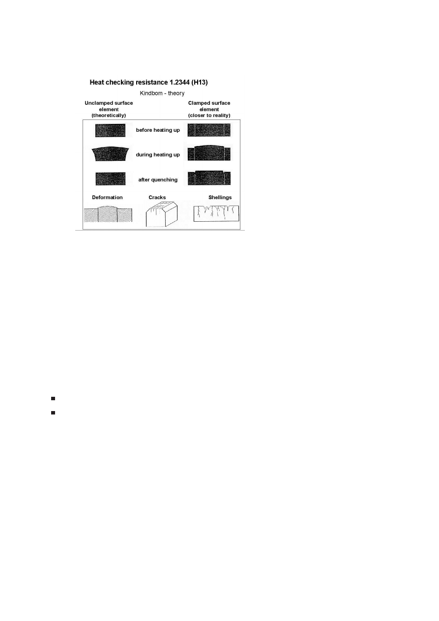
"Kindbom-Theory" as it can be seen in Fig. 1. [1,2] Theoretically an un-
Figure 1.
Kindbom – theory.
clamped surface element extends elastically during heating-up and constricts
elastically to its original state after quenching. The theory closer to reality
implies that the surface elements are clamped by neighbour ones and can
only extend in one direction during heating. The resulting state of stress
causes an elastic and in the end a plastic deformation of the clamped surface
element. During quenching, the surface element constricts in all directions
whereby cracks between the surface elements are induced.
The most typical resulting kinds of damage due to thermal shock loading
are described in Fig. 1 too. Deformation is the primary stage of thermal
shock damage. Cracks are the second stage and they represent the major
resulting kind of damage. The final stage are shellings which normally occur
after cracks have extended or grown together.
So far formulas describing the thermal fatigue behaviour include proper-
ties like:
yield strength
thermal conductivity

864
6TH INTERNATIONAL TOOLING CONFERENCE
Young’s modulus
coefficient of thermal expansion
The toughness and ductility characteristics of the materials are not con-
sidered.
During the last two decades material specifications for hot work tool steels
have been developed with the aim of reaching a better potential for increased
live times. The special focus was set on impact bending values obviously
describing the toughness behaviour of the material. Due to improved pro-
duction methods even the highest requirements with regard to toughness
(f.e. North American Die Casting Association, General Motors, CNOMO,
French automobile producers) can be met, however there was no link so far
between those values and heat checking behaviour.
GOAL OF THE INVESTIGATION
To prove a possible correlation between heat checking resistance and
toughness behaviour of hot work tool steel 1.2344 corresponding tests were
carried out on specimens with constant hardness levels. With reference to the
difference of ductility on one hand and toughness on the other hand notched
Charpy-V specimens as well as unnotched specimens were checked. The
results were compared with the thermal fatigue behaviour of correspond-
ing samples on a fatigue testing stand mainly with temperatures as high as
700
◦
C .
EXPERIMENTAL PROCEDURE
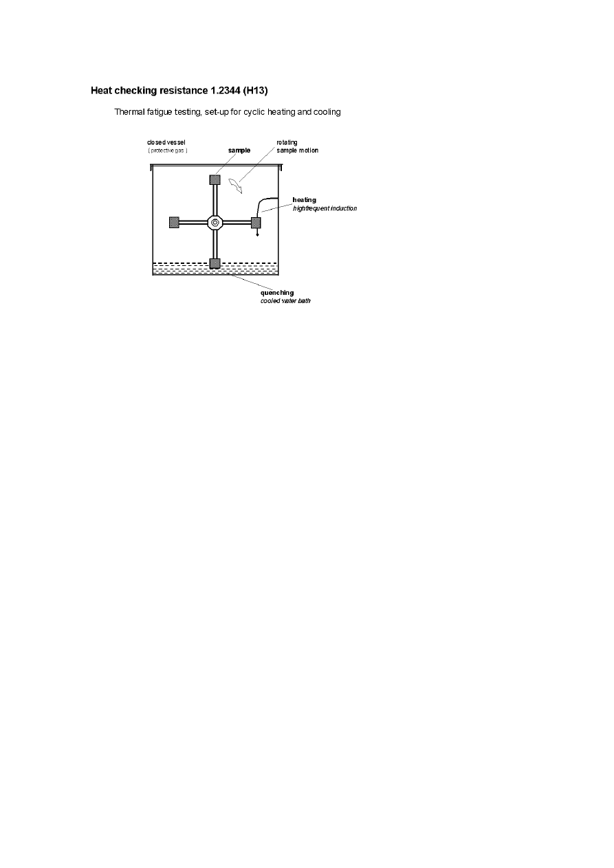
In order to check the thermal fatigue behaviour a test stand was used which
allows to expose rectangular specimens to a cyclic heating and cooling. For
this purpose the specimens are mounted on a wheel so that every specimen
while rotating runs through a heating and subsequently a cooling device,
Fig. 2. With respect to a surface near introduction of the thermal energy the
heating takes place by induction with a frequency of 250 kHz. The generator
power is 15 kW. To be quenched the specimens dive into a water bath which
temperature is kept constant with cooling pipes.
Figure 3 shows all important features of the complete device schemati-
cally. The generator power is led to the induction loop across an impedance
matching device and automatically switched on after the specimen rotated
Correlation Between Heat-Checking Resistance and Impact Bending Energy...
865
Figure 2.
Thermal fatigue testing, set-up for cyclic heating and cooling.
into the heating position. The maximum surface temperature of the spec-
imens is controlled by the programmable switch-on time of the generator.
Besides the sequence of the rotation of the specimens as well as the number of
thermal cycles can be computer controlled. By means of the programmable
leading control also the specimen temperature, the temperature of the water
bath and the actual number of cycles can be monitored and stored.
If the test stand is equipped with 4 specimens, the quenching time in the
water bath necessarily equals the time in the heating position. However due
to adjustment of the cooling of the water bath the quenching temperature of
the specimens can be varied slightly. Additionally it is possible to uncouple
the quenching time from the heating time as long as the test stand is equipped
only with two or one specimen with regard to the sample motion profile.
Due to the different adjustment of the generator power the heating speed
can be varied. With 100 % generator power the heating time from 100
◦
C to
700
◦
C is approximately 3 seconds (Fig. 4). Reducing the generator power
to 75 % the heating time increases to 5 s. Further power reduction to 50
respectively 25 % for heating to 700
◦
C increases the heating time to 9 re-
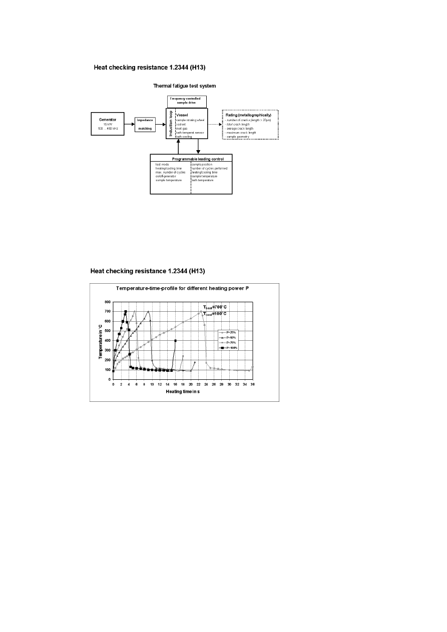
866
6TH INTERNATIONAL TOOLING CONFERENCE
Figure 3.
Thermal fatigue test – system.
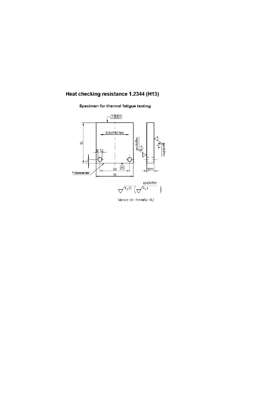
spectively 23 seconds. The size of the specimen is 50 × 55 × 10 mm
3
, see
Figure 4.
Temperature-time-profile for different heating power P.

Correlation Between Heat-Checking Resistance and Impact Bending Energy...
867
Fig. 5. A fine ground surface finish was used to avoid crack initiation due
to grinding grooves.
The geometric design of the induction loop causes that the electromag-
netic energy is transformed into heat only in a certain area of the specimen.
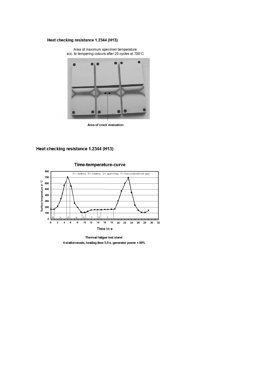
The area with the highest specimen temperature can be recognized according
to the tempering colours on the surface of the specimen after a small number
of thermal cycles (Fig. 6). According to this appearance the highest tem-
peratures develop only in a relatively small specimen area extending to the
sample corners. The most homogenious area lies in the middle of the speci-
men approximately 11 mm below the specimen corner. The metallographic
evaluation of the heat checking cracks is carried out in this area.
The number of cracks with a length of more than 20 µm as well as the
summarized length of those cracks allow judgment of the thermal fatigue
behaviour. Additional features like variations of the specimen geometry can
be used to characterize the heat checking resistance.
As test material the hot work tool steel according to DIN Standard 1.2344
ESR produced to meet the NADCA specification was used. Besides the
impact bending test specimens, which were cut from the short transverse
direction in the core area of bars out of different heats, the specimens for the
heat checking test were taken out of the transition area of the same material.
Following raw machining the specimens were hardened and tempered
twice to a hardness-level of 45 ± 1 HRC. After heat treatment they were fine
ground with a surface roughness of 4 µm. All specimens where additionally
demagnetized and thoroughly cleaned.
The examination of the heat checking resistance was performed with 4
specimens on the test wheel. The generator power was set to 80 %. The
maximum specimen temperature was adjusted to 700
◦
C . With a constant
water bath temperature of 60
◦
C and a dip in depth of the specimen of 20 mm
the minimum temperature after quenching reached 105
◦
C .
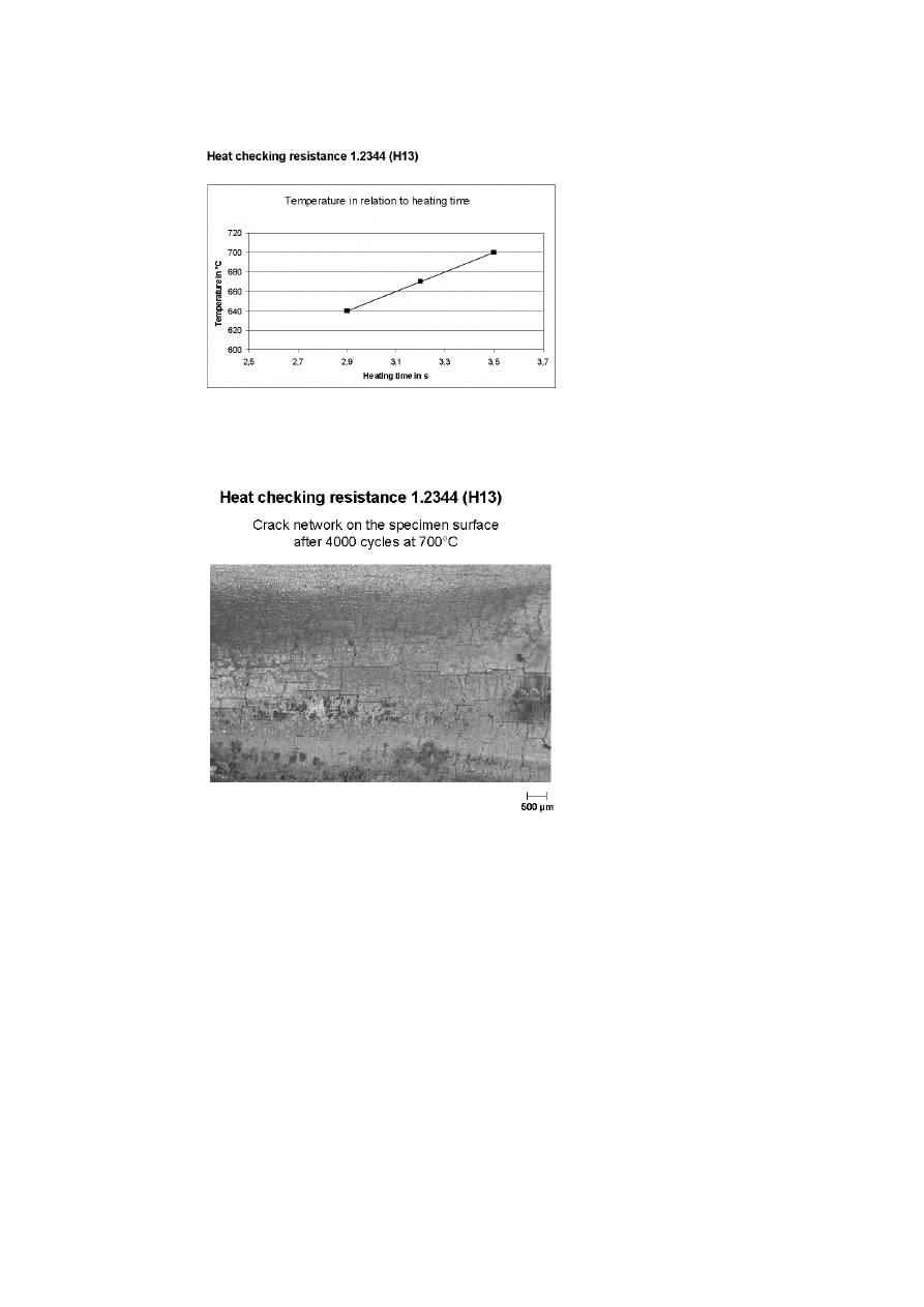
Figure 7 shows the temperature flow in the area of the crack rating over a
complete cycle. The heating to 700
◦
C takes 3.5 seconds which corresponds
to a temperature changing speed of 150 K/s. During quenching this speed
is 170 K/s. One complete temperature cycle takes 18 seconds. This is ex-
plained due to the fact, that every specimen runs through two free positions
between quenching and next heating. At these positions the surface temper-
ature of the sample rises of approx. 50
◦
C due to heat penetrating form the
core to the surface.
868
6TH INTERNATIONAL TOOLING CONFERENCE
Figure 5.
Specimen for thermal fatigue testing.

Correlation Between Heat-Checking Resistance and Impact Bending Energy...
869
The duration of the test was set to 4000 cycles. Besides the main tested
temperature of 700
◦
C some tests were carried out with 650
◦
C .
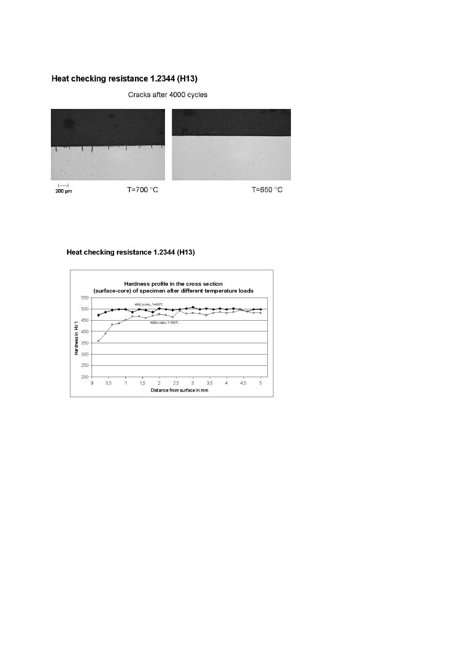
The necessary time to reach the maximum specimen temperature with
given generator power was established in pretests. During those tests NiCr-
Ni thermocouples where spot welded onto the evaluation area in order to
adjust the temperature in correlation to the induction heating time. For
example a lowering of the specimen temperature from 700
◦
C to 650
◦
C for
test material 2344 decreases the heating time from 3.5 seconds to 3 seconds
(Fig. 8 ).
To avoid corrosion on the specimens the closed test vessel was floated
with argon. Additionally the pH-value of the water bath was kept at 10,5.
Besides the basic pH-value helps to improve the moistening of the specimens
during quenching.
RESULTS
The periodic change of tension and compression caused by the tempera-
ture changes leads to the typical network of fatigue cracks. Figure 9 shows
their appearance after 4000 temperature cycles between 700
◦
C and105
◦
C .
The cracks predominantly orientate in the direction of the ground surface
finish but also develop transverse to that direction. For the quantitative judg-
ment of the heat checking resistance the elapsed time to the first occurance
of surface cracks would be a suitable but time consuming feature. Therefore
the number of cracks and the summarized crack length examined metallo-
graphically on the not etched specimen cross section from the area of the
maximum temperature were used.
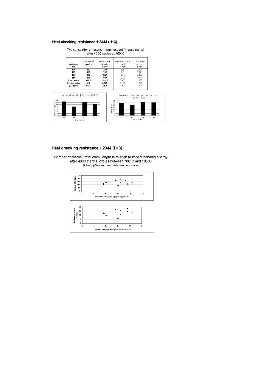
Corresponding microscopic photographs of the existing fatigue cracks
after 4000 temperature cycles at a specimen temperature of 700
◦
C as well
as 650
◦
C for comparison are shown in Fig. 10 . While after the test at
650
◦
C no cracks could be determined the increased temperature of 700
◦
C led
to numerous fatigue cracks developing in the direction surface to core. The
maximum length of single cracks reaches up to 1 mm, the average crack
length measures 0,1 mm. Additional examination of the crack characteristics
shows that the crack propagation is intergranular as well as transgranular.
The thermal loading of the specimens caused by the temperature cycles
leads besides the development of fatigue cracks also to a tempering effect
in the surface area. After 4000 cycles at 700
◦
C a low-load hardness check
(Vickers 1 g) shows that the hardness in the surface drops to 350 HV1 (Fig.

870
6TH INTERNATIONAL TOOLING CONFERENCE
11). Towards the specimen core, a rapid hardness increase is measurable over
a depth of approx. 2 mm. In deeper areas the loss in hardness is not as rapid
anymore and the original hardness of the specimen of 490 HV 1 is reached at a
depth of about 4,5 mm. Compared to the maximum temperature of 700
◦
C the
specimens heated to 650
◦
C show a remarkable lower loss of hardness in the
surface area. The surface hardness of these specimens measures 460 HV 1.
Already at a depth of 1 mm the original specimen hardness is reached.
In order to judge the results an average out of each specimen set containing
four specimens was built. With regard to the repeatability of the results a
comparison of the values of every single specimen in one set is of interest.
Figure 12 shows a corresponding list for the set containing specimens 10 F
to 13 F. While the main results are number of cracks and total length of cracks
also the maximum crack length and the average crack length were measured
(Fig. 12 ). Apart from specimen 11 F with lower values the number of
cracks as well as the total crack length for the remaining 3 specimens show a
satisfying scatter of 3 respectively 9 %. Including specimen 11 F the scatter
increases to 10 % for the number of cracks and 18 % for the total crack length.
Against that the maximum length of the developing cracks is not suitable for
quantitative judgments because of the bigger variations of the results.
Finally the results of the heat checking tests after 4000 cycles between
700
◦
C and 105
◦
C were compared with the impact bending test results of the
same bars (heats). The specimen material was taken out of standard pro-
duction according to NADCA requirements (North American Die Casting
Association). Therefore the impact bending values fall into a relatively nar-
row band between 170 and 300 Joule for the unnotched samples and 10 to
22 Joule for the Charpy-V-samples.
With regard to Fig. 13, no correlation could be found between the impact
bending values of the notched samples characterizing the crack propagating
speed and the number of fatigue cracks or their total length. Therefore the
coefficients of correlation only measure about 0,06 for the number of cracks
and 0,28 for the crack length respectively.
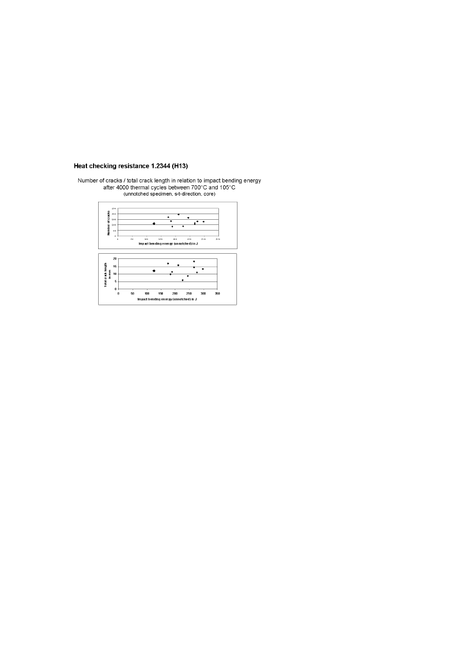
Also the impact bending values of the unnotched samples, which char-
acterize the ductility of the material, do not show a correlation to the heat
checking resistance (Fig. 14). The according coefficients of correlation
amount to –0,03 respectively 0,08 for the number of cracks respectively the
total crack length.

Correlation Between Heat-Checking Resistance and Impact Bending Energy...
871
To verify the results some specimens were purposely overheated in heat
treatment. The material was austenitized with a temperature of 1150
◦
C followed
by two time tempering to achieve the typical hardness of 45 HRC. The over-
heated coarsened structure leads to a loss of toughness and ductility. The
according dots are marked specifically (Figs. 13 and 14). The impact bend-
ing test results of the unnotched samples average on 125 Joule, whereas the
notched samples come to 9 Joule. Even the heat checking test results of
these specimens don’t give an additional hint with regard to a correlation
between heat checking resistance and toughness respectively ductility.
CONCLUSION
Heat checking resistance respectively thermal fatigue behaviour is one
of the most important features with regard to failures in the field of die
casting. Although there are no standardized tests to check the thermal fatigue
behaviour, toughness and ductility values tested in the impact bending test
are a part of most worldwide specifications for hot work tool steel for die
casting dies.
The aim of this work was to find out whether there is a correlation between
heat checking test results and toughness characteristics. The set-up for the
heat checking test was developed by EWK and permits tests with precise
parameters.
The tested specimens out of steel grade DIN 1.2344 ESR do not show
an influence of ductility or toughness on the development of thermal fatigue
cracks. The results put an other light on the valuation of impact bending
strength data as a criterion for the performance of the according hot work
tool steel during working operation particularly with regard to heat checking
resistance.
Obviously this statement is only true for the examined parameters. At least
it opens the field for further investigations of the heat checking characteristics
of hot work tool steels and main influencing factors.
REFERENCES
[1] L. KINDBOM: Warmrißbildung bei der Temperaturwechselbeanspruchung von War-
marbeitswerkzeugen. Arch. Eisenhüttenwes. 35 (1964 ) 8, p. 773 - 780
[2] T.
M”ULLER,
Temperaturwechselbeständigkeit
von
Warmarbeitsstählen
und
beschichteten Baustählen. Dr.-Ing. thesis, RWTH Aachen, Germany, 1999

872
6TH INTERNATIONAL TOOLING CONFERENCE
[3] H. BRIEFS and M. WOLF, „Warmarbeitsstähle". Verlag Stahleisen Düsseldorf 1975.
[4] P. G ¨
UMPEL, „Deutsche und internationale Normung von Warmarbeitsstählen".
Thyssen Edelst. Techn. Ber. 5 (1979) 2, 88 – 96.
[5] Chrysler Corp. Manufacturing Standards. Hot-Work Tool Steel (NP-2080), Rev. April
1975.
[6] Stahl-Eisen-Prüfblatt SEP 1614 „Mikroskopische Prüfung von Warmarbeitsstählen /
Microscopic Inspection of Hot-work Tool Steels". Verlag Stahleisen mbH, Düsseldorf,
Germany, 1996.
[7] Premium Quality H-13 Steel Acceptance Criteria for Pressure Die Casting Dies:
NADCA nr 207-97. North American Die Casting Association, River Grove, Illinois,
USA, 1997.
[8] H. BERNS, E. HABERLING and F. WENDL, „Einfluss des Glühgefüges auf die
Zähigkeit von Warmarbeitsstählen". Thyssen Edelst. Techn. Ber. 11 (1985) 2, 150 –
157.
[9] P. G ¨
UMPEL, „Untersuchungen über Primärcarbide in Warmarbeitsstählen" Thyssen
Edelst. Techn. Ber. 9 (1983) 2, 121 – 123
[10] L.-A. NORSTRÖM, „Ductility and Toughness in Hot-work Die steels: The Importance
of Proper test Procedures". Transactions of the NADCA 15th International Die Casting
Congress and Exhibition, St. Louis, Mo., 1989, Paper No. G-T89-014
[11] H. JESPERSON, M. KLAUCK and P. ROCHE, „Is Impact Testing Improving Die
Performance?". Die Casting Engineer, (199), 52-60
Correlation Between Heat-Checking Resistance and Impact Bending Energy...
873
Figure 6.
Area of maximum specimen temperature acc. to tempering colours after 20
cycles at 700
◦
C.
Figure 7.
Time-temperature-curve.
874
6TH INTERNATIONAL TOOLING CONFERENCE
Figure 8.
Temperature in relation to heating time.
Figure 9.
Crack network on the specimen surface after 4000 cycles at 700
◦
C.
Correlation Between Heat-Checking Resistance and Impact Bending Energy...
875
Figure 10.
Cracks after 4000 cycles.
Figure 11.
Hardness profile in the cross section (surface-core) of specimen after different
temperature loads.
876
6TH INTERNATIONAL TOOLING CONFERENCE
Figure 12.
Typical scatter of results in one test set (4 specimens) after 4000 cycles at
700
◦
C.
Figure 13.
Number of cracks / total crack length in relation to impact bending energy after
4000 thermal cycles between 700
◦
Cand 105
◦
C(Charpy-V- specimen, s-t-direction, core).
Correlation Between Heat-Checking Resistance and Impact Bending Energy...
877
Figure 14.
Number of cracks / total crack length in relation to impact bending energy after
4000 thermal cycles between 700
◦
Cand 105
◦
C(unnotched specimen, s-t-direction, core).
Wyszukiwarka
Podobne podstrony:
54 767 780 Numerical Models and Their Validity in the Prediction of Heat Checking in Die
Glow Worm installation and service manual Energy Saver 60 UI
26 349 359 PM Plastics Mould Steels Wear Resistant and Corrosion Resistant Martensitic Steels
On The Relationship Between A Banks Equity Holdings And Bank Performance
Resistance and counter hegemony in transboundry river basins Ana Elisa Cascão
Glow Worm installation and service manual Energy Saver 60 UI
Is There Historical Evidence for the Resurrection of Jesus A Debate between William Lane Craig and B
Posttraumatic Stress Symptomps Mediate the Relation Between Childhood Sexual Abuse and NSSI
Association between cancer screening behavior and family history among japanese women
1350 Checking condition and tension of V belts
Mechanical evaluation of the resistance and elastance of post burn scars after topical treatment wit
#0657 – Checking Accounts and Writing Checks
A comparative study on heat pump, microwave and freeze drying of fresh fruits
Avoidant or Ambivalent Attachment Style as a Mediator between Abusive Childhood Experiences and Adul
Stephani Hecht EMS Heat 14 Tagged and Bagged
Resistance and the background conversations of change
Relations between organizational culture identity and image
więcej podobnych podstron