
|
|
|
|
|
|
|
|
|
|
|
|
|
|
|
|
|
|
|
|
|
|
|
|
|
|
|
|
|
|
|
|
|
|
|
|
|
|
|
|
|
|
|
|
|
|
|
|
|
|
|
|
|
|
|
|
|
|
|
|
|
|
|
|
|
|
|
|
|
|
|
|
|
|
|
|
|
|
|
|
|
|
|
|
|
|
|
|
|
|
|
|
|
|
|
|
|
|
|
|
|
|
|
|
|
|
|
|
|
|
|
|
|
|
|
|
|
|
|
|
|
|
|
|
|
|
|
|
|
DRAFT FOR DEVELOPMENT
DD ENV
1992-4:2000
ICS: 91.080.040
NO COPYING WITHOUT BSI PERMISSION EXCEPT AS PERMITTED BY COPYRIGHT LAW
Eurocode 2: Design of
concrete structures Ð
Part 4: Liquid retaining and containing
structures
(together with United Kingdom National
Application Document)
Licensed copy:Heriot Watt University, 20/04/2004, Uncontrolled Copy, © BSI

This Draft for Development,
having been prepared under the
direction of the Building and Civil
Engineering Sector Committee,
was published under the
authority of the Standards
Committee and comes into effect
on 15 August 2000
BSI 08-2000
The following BSI references
relate to the work on this
standard:
Committee reference B/525/2
ISBN 0 580 33211 X
DD ENV 1992-4:2000
Amendments issued since publication
Amd. No.
Date
Comments
Committees responsible for this
British Standard
The preparation of this British Standard was entrusted to Technical Committee
B/525/2, Sturctural use of concrete, upon which the following bodies were
represented:
Association of Consulting Engineers
British Cement Association
British Precast Concrete Federation Ltd.
Concrete Society
Institution of Civil Engineers
Institution of Structural Engineers
Licensed copy:Heriot Watt University, 20/04/2004, Uncontrolled Copy, © BSI

DD ENV 1992-4:2000
BSI 08-2000
i
Contents
Page
Committees responsible
Inside front cover
National foreword
ii
Text of National Application Document
iii
Text of ENV 1992-4
2
Licensed copy:Heriot Watt University, 20/04/2004, Uncontrolled Copy, © BSI

ii
BSI 08 2000
DD ENV 1992-4:2000
National foreword
This Draft for Development was prepared by Subcommittee B/525/2 and is the official
English language version of ENV 1992-4:1998 Eurocode 2: Design of concrete
structures Ð Part 4: Liquid retaining and containment structures, as published by
the European Committee for Standardization (CEN). This Draft for Development also
includes the United Kingdom (UK) National Application Document (NAD) to be used
with the ENV in the design of structures to be constructed in the UK.
ENV 1992-4:1998 results from a programme of work sponsored by the European
commission to make available a common set of rules for the structural and
geotechnical design of building and civil engineering works.
This publication should not be regarded as a British Standard.
An ENV is made available for provisional application, but does not have the status of a
European Standard. The aim is to use the experience gained to modify the ENV so that
it can be adopted as a European Standard. The publication of this ENV and its National
Application Document should be considered to supersede any reference to a British
Standard in previous DD ENV Eurocodes concerning the subject covered by these
documents.
The values for certain parameters in the ENV Eurocodes may be set by individual CEN
Members so as to meet the requirements of national regulations. These parameters are
designated by
_
in the ENV.
During the ENV period of validity, reference should be made to supporting documents
listed in the National Application Document (NAD).
The purpose of the NAD is to provide essential information, particularly in relation to
safety, to enable the ENV to be used for structures constructed in the UK and the NAD
takes precedence over the corresponding provisions in the ENV.
The Building Regulations 1991, Approved Document A 1992, draws attention to the
potential use of ENV Eurocodes as an alternative approach to Building Regulation
compliance. ENV 1992-4:1998 is considered to offer such an alternative approach, when
used in conjunction with its NAD.
Users of this document are invited to comment on its technical content, ease of use
and any ambiguities or anomalies. These comments will be taken into account when
preparing the UK national response to CEN on the question of whether the ENV can
be converted to an EN.
Comments should be sent in writing to the Secretary of Subcommittee B/525/2,
BSI, 389 Chiswick High Road, London, W4 4AL, quoting the document reference, the
relevant clause and, where possible, a proposed revision, by 1st March 2001.
Summary of pages
This document comprises a front cover, an inside front cover, pages i to vi, the ENV
title page, pages 2 to 18, an inside back cover and a back cover.
Licensed copy:Heriot Watt University, 20/04/2004, Uncontrolled Copy, © BSI

BSI 08 2000
iii
National Application Document
for use in the UK with ENV 1992-4:1998
Licensed copy:Heriot Watt University, 20/04/2004, Uncontrolled Copy, © BSI

iv
BSI 08 2000
DD ENV 1992-4:2000
Contents of
National Application Document
Page
Introduction
v
1
Scope
v
2
Partial factors, combination factors and other values
v
3
Reference standards
v
4
Additional recommendations
v
Table 1 Ð Reference to EC2: Part 4 to other codes and standards
v
Licensed copy:Heriot Watt University, 20/04/2004, Uncontrolled Copy, © BSI

DD ENV 1992-4:2000
BSI 08-2000
v
Table 1 Ð Reference in EC2:Part 4 to other codes and standards
Reference in
EC2:Part 4
Document referred to
Document title or
subject area
Status
UK document
Various
ENV 1992-1-1
Design of concrete
structures. General
rules for buildings
Published 1991
DD
ENV1992-1-1:1992
2.3.3.1 Table 2.102
ENV 1991-1
Basis of design and
actions on
structures
Published 1994
DD ENV 1991-1:1996
2.3.3.1(109)
Eurocode 7
(ENV 1997-1)
Geotechnical
design: General
rules
Published 1994
DD ENV 1997-1:1995
National Application Document
Introduction
This National Application Document (NAD) has been
prepared under the direction of the Building and
Civil Engineering Sector Committee. It has been
developed from:
a) a textual examination of ENV 1992-4:1998;
b) a parametric calibration against BS 8110, BS
8007, supporting standards and test data.
1 Scope
This NAD provides information to enable ENV
1992-4:1998 (hereafter referred to as EC2: Part 4) to
be used for the design of structures to be
constructed in the UK. It will be used in conjunction
with DD ENV 1992-1-1:1992, the NAD of which refers
to BSI publication for values of actions.
2 Partial factors, combination factors
and other values
a) The values for combination coefficients (
ψ
)
given in Table 1 of the NAD for EC2:Part 1.1 are
not appropriate and a value of 1 for
ψ
0
,
ψ
1
and
ψ
2
should be applied to the operating load as given
in 2.2.2.3 (103) of EC2:Part 4.
b) The values for partial factors for normal
temperature design should be those given
in 2.3.3.1 of EC2:Part 4.
3 Reference standards
Supporting standards including materials
specification and standards for construction are
listed in Table 1 of this NAD.
4 Additional recommendations
4.1 Clause 1 Introduction
a) Sub-clause 1.1.2 (102)
Reference should also be made to BS 8007 or
CIRIA Report 139 for details of water excluding
structures.
4.2 Clause 4 Section and member design
a) Sub-clause 4.4.2.4 (109)
This Sub-clause should be revised as follows:
ªFor members subject predominantly to intrinsic
imposed deformations (e.g. thermal contraction or
shrinkage) the minimum mean strain e
sm,min
should be taken as that given by equation (4.184).
For strains less than e
sm,min
crack widths are
constant at spacings generally greater than that
given by equation (4.82).
e
sm,min
= 0.6k
c
kf
ct,ef
(4.184)
+
A
ct
Es
A
s
1
Ec
The definition of the symbols is as in 4.4.2.2 of
part 1. There is no necessity to take any further
measures to deal with the long term effects.º
4.3 Clause 5 Detailing provisions
a) Sub-clause 5.4.7.6 (102)
Reference should be made to BS 8007 for
semi-continuous types of construction.
b) Sub-clause 5.4.7.6 (103)
Reference should be made to BS 8007 or CIRIA
Report 139 for construction details.
Licensed copy:Heriot Watt University, 20/04/2004, Uncontrolled Copy, © BSI

blank
Licensed copy:Heriot Watt University, 20/04/2004, Uncontrolled Copy, © BSI

CEN
European Committee for Standardization
Comite EuropeÂen de Normalisation
EuropaÈisches Komitee fuÈr Normung
Central Secretariat: rue de Stassart 36, B-1050 Brussels
1998 CEN All rights of exploitation in any form and by any means reserved worldwide for CEN national
Members.
Ref. No. ENV 1992-4:1998 E
EUROPEAN STANDARD
ENV 1992-4
NORME EUROPE
 ENNE
EUROPA
È ISCHE NORM
December 1998
ICS 91.010.30; 91.080.40
Descriptors: civil engineering, buildings, concrete structures, design, building codes, compulation
English version
Eurocode 2: Design of concrete structures Ð Part 4: Liquid
retaining and containment structures
Eurocode 2: Calcul des structures en beÂton Ð
Partie 4: Structures de souteÁnement et reÂservoirs
Eurocode 2: Planung von Stahlbeton- und
Spannbetontragwerken Ð Teil 4: StuÈtz- und
BehaÈlterbauwerke aus Beton
This European Standard was approved by CEN on 27 May 1997 as a prospective
standard for provisional application.
The period of validity of the ENV is limited initially to three years. After two years
the members of CEN will be requested to submit their comments, particularly on
the question whether the ENV can be converted into a European Standard.
CEN members are required to announce the existence of this ENV in the same way
as for an EN and make the ENV available promptly at national level in an
appropriate form. It is permissible to keep conflicting national standards in force (in
parallel to the ENV) until the final decision about the possible conversion of the
ENV into an EN is reached.
CEN members are the national standards bodies of Austria, Belgium, Czech
Republic, Denmark, Finland, France, Germany, Greece, Iceland, Ireland, Italy,
Luxembourg, Netherlands, Norway, Portugal, Spain, Sweden, Switzerland and
United Kingdom.
Licensed copy:Heriot Watt University, 20/04/2004, Uncontrolled Copy, © BSI

Page 2
ENV 1992-4:1998
BSI 08-2000
Foreword
Objectives of the Eurocodes
(1) The ªStructural Eurocodesº comprise a group of
standards for the structural and geotechnical design of
buildings and civil engineering works.
(2) They cover execution and control only to the
extent that is necessary to indicate the quality of the
construction products, and the standard of the
workmanship needed to comply with the assumptions
of the design rules.
(3) Until the necessary set of harmonized technical
specifications for products and for the methods of
testing their performance are available, some of the
Structural Eurocodes cover some of these aspects in
informative Appendices.
Background of the Eurocode Programme
(4) The Commission of the European Communities
(CEC) initiated the work of establishing a set of
harmonized technical rules for the design of building
and civil engineering works which would initially serve
as alternatives to the different rules in force in the
various Member States and would ultimately replace
them. These technical rules became known as the
ªStructural Eurocodesº.
(5) In 1990, after consulting their respective Member
States, the CEC transfe rred the work of further
development, issue and updating of the Structural
Eurocodes to CEN, and the EFTA Secretariat agreed to
support the CEN work.
(6) CEN Technical Committee CEN/TC 250 is
responsible for all Structural Eurocodes.
Eurocode Programme
(7) Work is in hand on the following Structural
Eurocodes, each generally consisting of a number of
parts:
EN 1991 Eurocode 1, Basis of design and actions
on structures;
EN 1992 Eurocode 2, Design of concrete structures;
EN 1993 Eurocode 3, Design of steel structures;
EN 1994 Eurocode 4, Design of composite steel and
concrete structures;
EN 1995 Eurocode 5, Design of timber structures;
EN 1996 Eurocode 6, Design of masonry structures;
EN 1997 Eurocode 7, Geotechnical design;
EN 1998 Eurocode 8, Design provisions for
earthquake resistance of structures;
EN 1999 Eurocode 9, Design of aluminium alloy
structures.
(8) Separate sub-committees have been formed by
CEN/TC 250 for the various Eurocodes listed above.
(9) This Part 4 of Eurocode 2 is being published as a
European Prestandard (ENV) with an initial life of
three years.
(10) This Prestandard is intended for experimental
application and for the submission of comments.
(11) After approximately two years CEN members will
be invited to submit formal comments to be taken into
account in determining future actions.
(12) Meanwhile feedback and comments on this
Prestandard should be sent to the Secretariat of
CEN/TC 250/SC 2 at the following address:
Deutsches lnstitut fuÈr Normung e.V. (DIN)
Burggrafenstrasse 6
D Ð 10787 Berlin
phone: (+49) 30 ± 26 01 ± 25 01
fax: (+49) 30 ± 26 01 ± 12 31
National Application Documents (NADs)
(13) In view of the responsibilities of authorities in
member countries for safety, health and other matters
covered by the essential requirements of the
Construction Products Directive (CPD), certain safety
elements in this ENV have been assigned indicative
values which are identified by [ ] (ªboxed valuesº). The
authorities in each member country are expected to
assign definitive values to these safety elements.
(14) Some of the supporting European or international
standards may not be available by the time this
prestandard is issued. it is therefore anticipated that a
National Application Document (NAD) giving definitive
values for the safety elements, referencing compatible
supporting standards and providing national guidance
on the application of this prestandard, will be issued
by each member country or its Standards Organisation.
(15) It is intended that this Prestandard is used in
conjunction with the NAD valid in the country where
the building or civil engineering works is located.
Matters specific to this prestandard
(16) The scope of Eurocode 2 is defined in 1.1.1 of
ENV 1992-1-1 and the scope of this part of Eurocode 2
is defined in 1.1.2. Other additional parts of
Eurocode 2 which are already issued as ENV are
indicated in 1.1.3 of ENV 1992-1-1; these cover
additional technologies or applications, and
complement and supplement this part.
(17) In using this prestandard in practice, particular
regard should be paid to the underlying assumptions
and conditions given in 1.3 of ENV 1992-1-1.
(18) The five chapters of this prestandard are
complemented by three informative appendices. These
appendices have been introduced to provide general
information on material and structural behaviour
which may be used in the absence of information
specifically related to the actual materials used or
actual conditions of service.
(19) As indicated in paragraph (14) of this Foreword,
reference should be made to National Application
Documents which will give details of compatible
supporting standards to be used. For this part of
Eurocode 2, particular attention is drawn to the
approved prestandard ENV 206 (Concrete Ð
performance, production, placing and compliance
criteria).
Licensed copy:Heriot Watt University, 20/04/2004, Uncontrolled Copy, © BSI

Page 3
ENV 1992-4:1998
BSI 08-2000
For ENV 1992-4, the following additional subclauses
apply.
(20) This part 4 of Eurocode 2 complements
ENV 1992-1-1 for the particular aspects of liquid
retaining and structures for the containment of
granular solids.
(21) The framework and structure of this part 4
correspond to ENV 1992-1-1. However, part 4 contains
Principles and Application Rules which are specific to
liquid retaining and containment structures.
(22) Where a particular subclause of ENV 1992-1-1 is
not mentioned in this ENV 1992-4, that subclause of
ENV 1992-1-1 applies as far as deemed appropriate in
each case.
Some Principles and Application Rules of ENV 1992-1-1
are modified or replaced in this part, in which case the
modified versions supersede those in ENV 1992-1-1 for
the design of liquid retaining or containment
structures.
Where a Principle or Application Rule in ENV 1992-1-1
is modified or replaced, the new number is identified
by the addition of 100 to the original number. Where a
new Principle or Application Rule is added, it is
identified by a number which follows the last number
in the appropriate clause in ENV 1992-1-1 with 100
added to it.
A subject not covered by ENV 1992-1-1 is introduced in
this part by a new subclause. The subclause number
for this follows the most appropriate clause number in
ENV 1992-1-1.
(23) The numbering of equations, figures, footnotes
and tables in this part follow the same principles as
the clause numbering as described in (22) above.
Contents
Page
Foreword
2
1
Introduction
5
1.1
Scope
5
1.1.1
Scope of Part 4 of Eurocode 2
5
1.7
Special symbols used in Part 1 of
Eurocode 2
5
1.7.5
Special symbols used in Part 4 of
Eurocode 2
5
2
Basis of design
6
2.2
Definitions and classifications
6
2.2.2
Actions
6
2.2.2.3
Representative values of variable
actions
6
2.3
Design requirements
6
2.3.1
General
6
2.3.2
Ultimate limit states
6
Page
2.3.2.2
Combinations of actions
6
2.3.3
Partial safety factors for ultimate limit
states
6
2.3.3.1
Partial safety factors for actions on
structures
6
2.3.4
Serviceability limit states
7
2.5
Analysis
7
2.5.1
General provisions
7
2.5.1.1
General
7
2.5.6
Determination of the effects of
temperature
7
2.5.6.1
General
7
3
Material properties
8
3.1
Concrete
8
3.1.2
Normal weight concrete
8
3.1.2.5.4 Coefficient of thermal expansion
8
3.1.2.5.5 Creep and shrinkage
8
3.1.2.5.6 Specific heat capacity of concrete
8
3.1.2.6
Heat evolution and temperature
development due to hydration
8
4
Section and member design
9
4.1
Durability requirements
9
4.1.6
Abrasion
9
4.1.6.1
General
9
4.1.7
Surfaces of structures designed to
contain potable water
9
4.2
Design data
9
4.2.1
Concrete
9
4.2.1.5
Temperature effects due to hydration
of cement
9
4.3
Ultimate limit states
9
4.3.2
Shear
9
4.3.2.1
General
9
4.3.2.4
Elements requiring design shear
reinforcement
9
4.3.2.4.4 Variable strut inclination method
9
4.3.6
Design for dust explosions
9
4.3.6.1
General
9
4.3.6.2
Design of structural elements
9
4.4
Serviceability limit states
9
4.4.2
Limit states of cracking
9
4.4.2.1
General considerations
9
4.4.2.3
Control of cracking without direct
calculation
10
4.4.2.4
Calculation of crack width
11
Licensed copy:Heriot Watt University, 20/04/2004, Uncontrolled Copy, © BSI

Page 4
ENV 1992-4:1998
BSI 08-2000
Page
4.4.2.5
Minimizing cracking due to restrained
impaired deformations
11
5
Detailing provisions
14
5.3
Prestressing units
14
5.3.3
Horizontal and vertical spacing
14
5.3.3.2
Post-tensioning
14
5.3.4
Anchorages and couplers for
prestressing tendons
14
5.4
Structural members
14
5.4.7
Reinforced concrete walls
14
5.4.7.5
Corner connections between walls
14
5.4.7.6
Provision of movement joints
14
5.4.9
Prestressed walls
14
5.4.9.1
Minimum reinforcement areas
14
Informative Appendix 105 Effect of
temperature on the properties of concrete
16
Informative Appendix 106 Calculation of
strains and stresses in uncracked concrete
sections subjected to restrained imposed
deformations
17
Informative Appendix 107 Calculation of
leakage through cracks in elements retaining
liquids
17
Licensed copy:Heriot Watt University, 20/04/2004, Uncontrolled Copy, © BSI

Page 5
ENV 1992-4:1998
BSI 08-2000
1 Introduction
1.1 Scope
Replacement of clause 1.1.2 in ENV 1992-1-1 by:
1.1.1 Scope of part 4 of Eurocode 2
P(l01) Part 4 of Eurocode 2 covers the design of
structures constructed from plain or lightly reinforced
concrete, reinforced concrete or prestressed concrete
for the containment of liquids or granular solids and
other liquid retaining structures.
P(l02) Principles and Application Rules are given in
this part for the design of those elements of structure
which directly support the stored liquids or materials
(i.e. the walls of tanks, reservoirs or silos). Other
elements which support these primary elements (for
example, the tower structure which supports the tank
in a water tower) should be designed according to the
provisions of part 1 except that the design actions
arising from the retained material will be calculated
according to the provisions of this part.
P(103) This part does not cover:
Ð structures for the storage of materials at very low
temperatures;
Ð structures for the storage of materials at very
high temperatures;
Ð structures for the storage of hazardous materials
the leakage of which could constitute a major health
or safety risk;
Ð the selection and design of liners;
Ð design for resistance to fire. This is covered by
part 1-2 of Eurocode 2 or by national provisions;
Ð no-fines concrete and aerated concrete
components, and those made with heavy aggregate
or containing structural steel sections (see Eurocode
4 for composite steel-concrete structures);
Ð pressurised vessels;
Ð floating structures;
Ð structures subjected to significant seismic actions
(design for seismic actions is covered in Eurocode 8).
(104) Storage of materials of very low temperatures
may be assumed where the temperature of the stored
material is 220 8C or less. For the storage of liquid
petroleum gas see EN 26502-2.
(105) Storage of materials of very high temperatures
may be assumed where the temperature of the stored
material exceeds 200 8C.
(106) For the selection and design of liners, reference
should be made to appropriate documents.
1.7 Special symbols used in part 1 of
Eurocode 2
Addition after 1.7.4.
1.7.5 Special symbols used in part 4 of
Eurocode 2
1.7.5.1 Latin upper case symbols
E
r
effective modulus of elasticity of the stored
material
L
c
the crack length (m)
Q
leakage rate in m
3
/s
Q
o
operating value of imposed load
Q
w
imposed load from a retained liquid
R
ax
factor defining the degree of external axial
restraint provided by elements attached to the
element considered
R
m
factor defining the degree of moment restraint
provided by elements attached to the element
considered
T
1
temperature of material in contact with
surface 1
T
2
temperature of material in contact with
surface 2
T
m
mean steady state temperature of a wall
1.7.5.2 Latin lower case symbols
f
ctx
tensile-strength, however defined
f
ckT
characteristic compressive strength of the
concrete modified to take account of
temperature
h
wall thickness in m
W
elf
effective crack width (m)
1.7.5.3 Greek symbols
a
r
a coefficient taking account of the moisture
content of the concrete
a
1
resistance to heat flux at surface 1
a
2
resistance to heat flux at surface 2
g
w
partial safety factor on load due to retained
liquid
D
r
pressure difference across the element
(N/mm
2
)
DT
ss
steady state temperature difference
e
av
average strain in the element
e
az
actual strain at level z
e
iz
imposed intrinsic strain at level z
e
Tr
transitional thermal strain
e
Th
free thermal strain in the concrete
l
c
conductivity of concrete
r
r
density of the stored material in kN/m
3
y
r
Poisson's ratio of stored material
s
z
vertical stress in stored material in kN/m
2
h
dynamic viscosity of liquid (kg/ms)
Licensed copy:Heriot Watt University, 20/04/2004, Uncontrolled Copy, © BSI

Page 6
ENV 1992-4:1998
BSI 08-2000
2 Basis of design
2.2 Definitions and classifications
2.2.2 Actions
2.2.2.3 Representative values of variable actions
Replacement of this subclause by:
P(l01) The main representative value is the
characteristic value, Q
k
. The representative value
corresponding to the specified quantity of the retained
material which the structure is designed to hold should
more properly be called the ªoperating valueº, Q
o
, but,
for convenience, the symbol Q
k
, will be used for this
operating value.
(102) In a liquid retaining structure where the
maximum level of the liquid can be clearly defined
and where the effective density of the liquid
(allowing for any suspended solids) will not vary
significantly, a lower safety factor, ,g
w
, than that in
Table 22 of ENV 1992-1-1 may be used on the
characteristic load due to the retained liquid, Q
w
.
(103) If not stated otherwise, the values of
ψ
0
,
ψ
1
and
ψ
2
applied to the operating load should be taken
as 1.0.
2.3 Design requirements
2.3.1 General
Addition after Principle P(4):
(105) The design situations to be considered should
comply with ENV 1991-4, clause 3. For liquid
retaining and containment structures made with
concrete, the following design situations may be
relevant:
Ð operating conditions implying patterns of
discharge and filling;
Ð explosions due to powder;
Ð thermal effects caused, for example, by stored
materials or environmental temperature;
Ð imposed deformations.
2.3.2 Ultimate limit states
2.3.2.2 Combinations of actions
Add a note below Table 2.1 in ENV 1992-1-1.
NOTE
Where g
w
is used for one of the variable actions, g
w
Q
w
is
substituted for the corresponding value of g
Q
Q
k
.
Replacement of Application Rules (5) to (8) by:
(105) Appropriate values for the characteristic actions
and appropriate combinations of actions are given in
Eurocode 1 part 4: Actions in silos and tanks.
2.3.3 Partial safety factors for ultimate limit
states
2.3.3.1 Partial safety factors for actions on structures
Replacement of Table 2.2 by:
Table Ð 2.102: Partial safety factors for
actions in containment structures for
persistent and transient situations
permanent
actions
variable
actions,
general
variable
actions
due to
retained
liquid
pre-
stressing
g
G
g
Q
g
w
g
p
Favourable
effect
[1,0]
*
**
**
***
[0.9] or
[1.0]
Unfavourable
effect
[1.35]
*
[1.5]
[1.2]
1)
[1.2] or
[1.0]
*
See also paragraphs (3) in this clause in part 1 and (109) below.
**
See Eurocode 1; in normal circumstances, g
Q,inf
= 0.
***
See relevant clauses.
1)
Covering model uncertainties, see ENV 1991-1, clause 9 and
annex A.
Replacement of Application Rule (8) by:
(108) By adopting the y values given in Table 2.102,
the expression [2.7(a)] may be replaced by the
following:
Ð for design situations with only one variable
action Q
k,1
or Q
w
:
∑
g
Gj
G
kj
+ 1,5 Q
k,1
or
1.2
Q
w
[2.108(a)]
Ð for design situations with two or more variable
actions:
∑
g
Gj
G
kj
+ 1.35
Q
k,i
+
1.2
Q
w
[2.108(b)]
i $ 1
S
whichever gives the most unfavourable effect.
Equations [2.108(a)] and [2.108(b)] should be used
only, if the conditions for the action Q
w
in 2.2.2.3 (102) are met. Otherwise, the partial safety
factor g
Q
= 1.5 should be applied to Q
w
.
(109) Actions resulting from soil or water within soil
are treated as permanent actions and should be
obtained in accordance with Eurocode 7. Actions
from retained materials in silos should be considered
as variable actions.
(110) It should be noted that, where backfill is
placed against the outside walls of a structure, it is
required that the safety should be checked both with
and without the soil present.
Licensed copy:Heriot Watt University, 20/04/2004, Uncontrolled Copy, © BSI

Page 7
ENV 1992-4:1998
BSI 08-2000
2.3.4 Serviceability limit states
Replacement of Application Rule (7) by:
(107) Where actions other than environmental
actions (wind, snow, temperature etc.) are being
considered, the rare combination may be simplified
to the following expressions, which may also be
used as a substitute for the frequent combination:
Ð design situations with only one variable
action, Q
k,1
:
∑
G
kj
(+P) + Q
k,1
[2.109(d)]
Ð design situations with two or more variable
actions, Q
kj
∑
G
kj
(+P) +
1.0
⋅ ∑
Q
kj
[2.109(e)]
whichever gives the more critical value.
Addition after Principle P(8):
(109) Acceptance criteria for liquid retaining
structures could include maximum level of leakage.
2.5 Analysis
2.5.1 General provisions
2.5.1.1 General
Addition after Application Rule (6):
P(107) Account shall be taken of the effects of
structure-soil interaction where these are significant.
Addition after 2.5.5:
2.5.6 Determination of the effects of temperature
2.5.6.1 General
(101) It will normally be adequate to use methods of
analysis based on the assumption of elastic
structural behaviour. However, allowance should be
made for the effects of creep, shrinkage and
cracking where these are likely to be significant.
(102) Rigorous analyses may be carried out using
Equation (2.22) in 2.5.5.1 of ENV 1992-1-1. It should
be noted that it will also be necessary to introduce
compatibility and/or equilibrium conditions to obtain
a solution [for example, in a fully restrained member
of uniform section,
ε
tot
(t
1
t
0
), has to be equal to zero
at all values of t].
(103) In many cases it will be sufficiently accurate to
carry out an elastic analysis on the basis of an
effective modulus of elasticity for the concrete
which has been adjusted to make allowance for the
effects of creep in accordance with Equation (2.24)
in 2.5.5.1 (12) in ENV 1992-1-1.
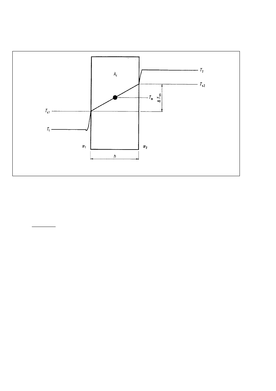
(104) Where a member is subjected to different
temperatures on opposite faces, the steady state
temperature difference across the wall is given by
Equation (2.125) below (see Figure 2.106):
DT
ss
=
(T
2
2 T
1
)
(2.125)
(h/l
c
)
a
1
+ (h/l
c
) + a
2
where
DT
ss
steady state temperature difference;
a
1
resistance to heat flux at surface 1. In the
absence of specific data for the situation
considered, the following values may be
adopted for a
1
:
0.005 m
2
8C/W for liquids;
0.110 m
2
8C/W for granular materials;
0.060 m
2
8C/W for ambient atmosphere
(this may be significantly affected by
wind).
a
2
resistance to heat flux at surface 2 (values
as for a
1
);
h
wall thickness in m;
l
c
conductivity of concrete which may be
taken as 1.75 W/m 8C in the absence of
better data;
T
l
temperature of material in contact with
surface 1;
T
2
temperature of material in contact with
surface 2 numerically higher than T
1
.
The mean steady state temperature of the wall may
be taken as:
T
m
= T
1
+
DT
ss
(2.126)
0.5 +
l
c
a
1
h
In Figure 2.106:
(2.127)
=
=
=
T
2
2 T
1
(a
1
+ (h/l
c
) + a
2
)
T
2
2 T
s2
a
2
DT
ss
(h/l
c
)
T
s1
2 T
1
a
1
(105) Where the mean temperatures in different,
monolithically connected, elements of a structure are
different, significant effects due to the restraint of
some members by others in the structure may
occur,. Where significant, these should be taken into
account.
(106) In silos, high temperature gradients may occur
where the stored material is either self heating or is
put into the silo at high temperature. In such
circumstances calculation of the resulting
temperature gradients and the consequent internal
forces and moments will be necessary. Two
situations may require consideration:
Ð high temperature gradients in the walls above
the bulk material due to hot air in an almost
empty silo;
Ð reduced wall temperature gradients due to heat
insulating effects of the bulk material in an almost
full silo.
Licensed copy:Heriot Watt University, 20/04/2004, Uncontrolled Copy, © BSI
Page 8
ENV 1992-4:1998
BSI 08-2000
Figure 2.106 Ð Steady state temperature state in a wall
(107) An increase in tensile forces and associated
moments may also occur where a drop in the
temperature outside the silo leads to the silo walls
shrinking onto the retained material. These forces
and moments may be calculated by estimating an
effective modulus of elasticity for the retained
material from the approximate relation:
E
r
=
(2.128)
3.09 r
r
1.5
s
z
(1 2 v
r
)
where
E
r
effective modulus of elasticity of the stored
material;
r
r
density of the stored material in kN/m
3
;
v
r
Poisson's ratio of stored material;
s
z
vertical stress in the stored material in
kN/m
2
.
3 Material properties
3.1 Concrete
3.1.2 Normal weight concrete
3.1.2.5.4 Coefficient of thermal expansion
Replacement of Principle P(1) by:
(101) Coefficients of thermal expansion of concrete
vary considerably depending on the aggregate type
and the moisture conditions within the concrete. In
the absence of information from tests on the
concrete to be used in the structure, a value of
10 3 10
26
/8C may be adopted.
3.1.2.5.5 Creep and shrinkage
Addition after Application Rule (5):
(106) Where the elements are exposed for
substantial periods to high temperature (>40 8C),
creep behaviour is substantially modified. Where this
is likely to be significant, appropriate data should
generally be obtained for the particular conditions of
service envisaged. Guidance is given in Informative
Appendix 105 on the estimation of creep effects at
elevated temperatures.
Addition after 3.1.2.5.5.
3.1.2.5.6 Specific heat capacity of concrete
(101) For design purposes, the specific heat capacity
of normal weight concrete may be taken as
1 000 J/kg 8C.
3.1.2.6 Heat evolution and temperature
development due to hydration
(101) The heat evolution characteristics for a
particular cement should generally be obtained from
tests. The actual heat evolution should be
determined taking account of the expected
conditions during the early life of the member (e.g.
curing, ambient conditions).
Licensed copy:Heriot Watt University, 20/04/2004, Uncontrolled Copy, © BSI

Page 9
ENV 1993-4:1998
BSI 08-2000
4 Section and member design
4.1 Durability requirements
Addition after 4.1.5.
4.1.6 Abrasion
4.1.6.1 General
(101) Abrasion of the inner face of the walls of a silo
may cause contamination of the stored material or
lead to significant loss of cover. Three mechanisms
of abrasion may occur:
Ð mechanical attack due to the filling and
discharging process;
Ð physical attack due to erosion and corrosion
with changing temperature and moisture
conditions;
Ð chemical attack due to reaction between the
concrete and the stored material.
(102) Appropriate measures should be taken to
ensure that the elements subject to abrasion will
remain serviceable for the period foreseen in the
design.
4.1.7 Surfaces of structures designed to contain
potable water
(101) Organic material in the concrete or in any
surface coating applied to the concrete which may
lead to fungal or bacterial growth should be avoided.
Reference should be made to relevant documents.
4.2 Design data
4.2.1 Concrete
Addition after 4.2.1.4.
4.2.1.5 Temperature effects due to hydration of
cement
(101) The maximum temperature rise and the time
of occurrence after casting should be established
from the mix design, the nature of the formwork
and the ambient conditions.
4.3 Ultimate limit states
4.3.2 Shear
4.3.2.1 General
Addition after Application Rule (7):
(108) Special measures are not needed to reinforce
for shear near the corners of silos or tanks where
the ultimate shear stress is less than the value given
by equation (4.18) in ENV 1992-1-1.
4.3.2.4 Elements requiring design shear
reinforcement
4.3.2.4.4 Variable strut inclination method
Replacement of Application Rule (8) by:
(108) The variable strut inclination method should
not be used in situations where the member
considered is subjected to a significant axial force
(either tensile or compressive).
Addition after 4.3.5.
4.3.6 Design for dust explosions
4.3.6.1 General
P(l01) Where silos are designed to contain materials
which may pose a risk of dust explosions, the
structure shall either be designed to withstand the
resulting expected maximum pressures or be provided
with suitable venting which will reduce the pressure to
a supportable level.
P(102) Fire expelled through a venting outlet shall not
cause any impairment of the surroundings nor cause
explosions in other sections of the silo. Risks to people
due to flying glass or other debris shall be minimised.
(103) Vent openings should lead directly to open air
through planned venting outlets, which reduce the
explosion pressure.
(104) Venting systems should, be initiated at low
pressure and have low inertia.
(105) Actions due to dust explosions should be
treated as accidental actions.
4.3.6.2 Design of structural elements
P(101) All structural elements shall be designed to
withstand the appropriate actions resulting from an
explosion which should be considered as an accidental
action (see 2.3.1 and 2.3.2.2 of this part 4).
(102) Indicative values for the rate of pressure
increase and maximum pressures for different types
of stored materials should be taken from appropriate
documents.
(103) The maximum pressures due to explosions
occur in empty silo bins, however, the pressure in a
partly filled silo bin combined with the
corresponding pressure from the bulk material may
lead to a more critical design condition.
(104) When inertia forces arise due to a rapid
discharge of gas followed by cooling of the hot
smoke, apressure below atmospheric may occur.
This should be taken into account when designing
the encasing structure and members in the flow
path.
(105) The elements forming a venting device should
be secured against flying off and adding to the risks
from flying debris.
(106) As pressure relief due to venting occurs,
reaction forces are generated which should be taken
into account in the design of structural members.
(107) Specialist assistance should be sought where
complex installations are contemplated or where
explosions might pose a high risk of injury.
4.4 Serviceability limit states
4.4.2 Limit states of cracking
4.4.2.1 General considerations
Addition after Principle P(9):
(110) It is convenient to classify liquid retaining
structures in relation to the degree of protection
against leakage required. Table 4.118 gives the
classification.
Licensed copy:Heriot Watt University, 20/04/2004, Uncontrolled Copy, © BSI

Page 10
ENV 1992-4:1998
BSI 08-2000
Table 4.118 Ð Classification of liquid retaining
structures
Class
Requirements for leakage
0
Some degree of leakage acceptable, or
leakage of liquids irrelevant.
1
Global tightness. Leakage to be limited to
minimal amount. Some surface staining or
damp patches ac eptable.
2
Local tightness. Leakage generally not
permitted. Appearance not to be impaired
by staining.
(111) Appropriate limits to cracking depending on
the classification of the element considered should
be agreed with the client, paying due regard to the
required function of the structure.
In the absence of more specific requirements, the
following may be adopted.
Class 0 Ð The provisions in 4.4.2 of ENV 1992-1-1
may be adopted.
Class 1 Ð Any cracks which can be expected to
pass through the full thickness of the
section should be limited to
0.2
mm
where healing of the cracks can be
expected to occur or
0.1
mm where
ealing is not expected. The provisions
in 4.4.2 of ENV 1992-1-1 apply where
the full thickness of the section is not
cracked and where the conditions in
(112) and (113) below are fulfilled.
Class 2 Ð Cracks which may be expected to pass
through the full thickness of the
section should be avoided unless
appropriate measures such as liners or
water bars have been incorporated to
ensure that leakage does not occur.
(112) To provide adequate assurance that cracks do
not pass through the full width of a section, the
design value of the depth of the compression zone
should be at least
50
mm calculated for the most
critical combination of actions including temperature
effects and shrinkage. The action effects may be
calculated on the assumption of a linear elastic
material behaviour. The resulting stresses in a
section should be calculated assuming that the
concrete tensile strength is zero.
(113) Where a crack may form on one side of an
element under one combination of actions and the
opposite side under another, then the cracks should
be considered to pass through the full thickness of
the section unless there is at least
50
mm of
concrete within the section which remains in
compression under all appropriate combinations of
actions.
(114) Leakage through a crack may be expected to
be proportional to the cube of the crack width.
Guidelines for the prediction of leakage through
cracks are given in Informative Appendix 107 of this
part 4.
(115) Cracks may be expected to heal in members
which are made with concrete with an appropriate
composition and which are not subjected to
significant changes of loading or temperature during
service. In the absence of more reliable information,
healing may be assumed where the annual range of
strain at a section is less than 150 3 10
26
.
(116) If self-healing is unlikely to occur, any crack
which passes through the full thickness of the
section may lead to leakage, regardless of the crack
width.
(117) Silos holding dry materials may generally be
designed as Class 0 however it may be appropriate
for a higher class to be used where the stored
material is particularly sensitive to moisture.
(118) If plain or lightly reinforced concrete is
subjected to stresses that will result in cracking, the
crack width will be uncontrollable. The use of plain
or lightly reinforced concrete should therefore be
limited.
(119) Special care should be taken where members
are subject to tensile stresses due to the restraint of
shrinkage or thermal movements.
4.4.2.3 Control of cracking without direct calculation
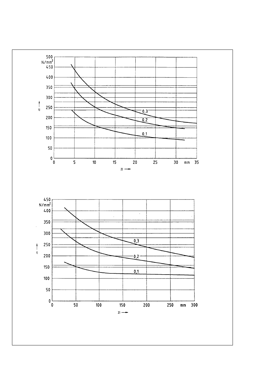
Replacement of Application Rule (2) by.
(102) Where at least the minimum reinforcement
given by 4.4.2.2 in ENV 1992-1-1 is provided, the
limitation of crack widths to appropriate values
having regard to the class of the member considered
(see Table 4.118) and the avoidance of uncontrolled
cracking between widely spaced bars may generally
be achieved by limiting either the bar spacings or
the bar diameters. Figures 4.134(a) and 4.134(b) or
Tables 4.115 and 4.116 below may be used to
establish appropriate maximum bar diameters or
maximum bar spacings for control of crack widths
to within the chosen limits. It should be noted that
larger cracks than those calculated for could
occasionally occur. Figures 4.134(a) and 4.134(b) and
Tables 4.115 and 4.116 are based on the crack width
formula (4.80) in 4.4.2.4 of ENV 1 992-1-1, except for
intrinsic imposed deformations for which the mean
strain e
sm
is calculated according to equation (4.184)
of this part 4.
Crack widths will not generally exceed the specified
limits provided that:
Ð for cracking caused predominantly by restraint,
the bar sizes given in Figure 4.134(a) and Table 4.115
are not exceeded where the steel stress is the value
obtained immediately after appearance of the first
crack (i.e. the stress used is as used in
Equation (4.78) in ENV 1992-1-1) and
Ð for cracks caused predominantly by loading,
either the provisions of Figure 4.134(a) and
Table 4.115 or the provisions of Figure 4.134(b) and
Table 4.116 are complied with.
For prestressed concrete sections, the stresses in the
reinforcement may be calculated regarding the
prestress as an external force without allowing for any
stress increase in the tendons due to loading.
Licensed copy:Heriot Watt University, 20/04/2004, Uncontrolled Copy, © BSI

Page 11
ENV 1992-4:1998
BSI 08-2000
For reinforced concrete the maximum bar diameter
obtained from Figure 4.134(a) or Table 4.115 may be
modified as follows:
for cracking caused predominantly by restraint:
f
s
= f
s
•
$
f
ctm
h
25 (h 2 d)
f
s
•
f
ctm
2.5
for cracking caused predominantly by loading:
f
s
= f
s
•
$ f
s
•
h
10 (h 2 d)
where
f
s
is the adjusted maximum bar diameter;
f
s
•
is the maximum bar size obtained from
Figure 4.134(a) or from Table 4.115;
h
is the overall depth or, in the case of a wall,
thickness, of the member;
d
is the effective depth of the member.
(103) In Figures 4.134(a) and 4.134(b) or Tables 4.115
and 4.116 respectively the steel stresses used should
be evaluated for reinforced concrete on the basis of
the quasi-permanent combination of actions and for
prestressed concrete on the basis of the frequent
combination of actions and the relevant estimate of
prestress. In Figure 4.134(a) and Table 4.115, if the
stresses arise predominantly from restraint then a
steel stress equal to (s
s
in Equation (4.78) in
ENV 1992-1-1 should be used.
4.4.2.4 Calculation of crack width
Addition after Application Rule (8):
(109) For members subject predominantly to
intrinsic imposed deformations (e.g. thermal
contraction or shrinkage) the last sentence
of 4.4.2.4(2) in ENV 1992-1-1 does not apply. In these
cases the mean strain, e
sm
, should be calculated
from Equation (4.184) rather than Equation (4.81) in
ENV 1992-1-1:
e
sm
= 0.6 k
c
k f
ct.ef
(4.184)
+
A
ct
E
s
A
s
1
E
c
The definitions of the symbols are as in 4.4.2.2 of
ENV 1992-1-1. There is no necessity to take any
further measures to deal with long term effects.
Addition after 4.4.2.4:
4.4.2.5 Minimizing cracking due to restrained
impaired deformations
(101) Where it is desirable to minimize the formation
of cracks due to restrained imposed deformations
resulting from temperature change or shrinkage, this
may be achieved for Class 1 structures (see
Table 4.118) by ensuring that the resulting tensile
stresses do not exceed the tensile strength f
ctk,0.05
of
the concrete and for Class 2 structures by ensuring
that the concrete section remains in fully
compression. This may be achieved by:
Ð limiting the temperature rise due to hydration
of the cement;
Ð removing or reducing restraints;
Ð reducing the shrinkage of the concrete;
Ð using concrete with a low coefficient of
thermal expansion;
Ð using concrete with a high tensile strain
capacity (Class 1 structures only);
Ð application of prestressing.
(102) It will generally be sufficiently accurate to
calculate the stresses assuming the concrete to be
elastic and to allow for the effects of creep by use of
an effective modulus of elasticity for the concrete.
Informative Appendix 106 provides a simplified
method of assessing stresses and strains in
restrained concrete members which may be used in
the absence of more rigorous calculation.
Licensed copy:Heriot Watt University, 20/04/2004, Uncontrolled Copy, © BSI
Page 12
ENV 1992-4:1998
BSI 08-2000
1) stress in reinforcement s
s
.
2) maximum bar spacing f
s
•
Figure 4.134a) Maximum bar diameters for crack control
1) stress in reinforcement s
s
.
2) maximum bar spacing s
Figure 4.134b) Ð Maximum bar spacing for crack control
Licensed copy:Heriot Watt University, 20/04/2004, Uncontrolled Copy, © BSI

Page 13
ENV 1992-4:1998
BSI 08-2000
Table 4.115 Ð Maximum bar diameters f
s
•
for high bond bars
Steel stress
Maximum bar size (mm) for w
k
=
(N/mm
2
)
0.3 mm
0.2 mm
0.1 mm
160
32
25
10
200
25
16
6
240
18
12
4
280
14
8
Ð
320
10
6
Ð
360
8
4
Ð
400
6
Ð
Ð
450
4
Ð
Ð
Table 4.116 Ð Maximum bar spacings s for high bond bars
Steel stress
Maximum bar size (mm) for w
k
=
(N/mm
2
)
0.3 mm
0.2 mm
0.1 mm
160
>300
220
40
200
280
125
Ð
240
190
70
Ð
280
125
40
Ð
320
80
Ð
Ð
360
50
Ð
Ð
400
30
Ð
Ð
Licensed copy:Heriot Watt University, 20/04/2004, Uncontrolled Copy, © BSI

Page 14
ENV 1992-4:1998
BSI 08-2000
Table 5.106 Ð Design of joints for the control of cracking
option
method of control
movement joint spacing
reinforcement
a)
Continuous Ð full restraint
Generally no joints, though some
widely spaced joints may be
desirable where a substantial
temperature range is expected
Reinforcement in accordance
with Chapters 4.3 and 4.4.2
b)
Close movement joints Ð
maximum freedom from restraint
Complete joints at greater of
5 m
or
1.5
times wall height
Reinforcement in accordance
with Chapter 4.3 but not less
than minimum given in 5.4.7.2
to 5.4.7.4.
5 Detailing provisions
5.3 Prestressing units
5.3.3 Horizontal and vertical spacing
5.3.3.3 Post-tensioning
Addition after Application Rule (1):
(102) In the case of circular tanks with internal
prestressing within the section, the theoretical
centroid of the horizontal cables should generally lie
in the outer third of the wall. Where the cover
provisions make this impossible, this
recommendation may be relaxed provided the
tendon duct remains within the outer half of the
wall.
(103) The diameter of a duct within a wall should
not exceed 1/5th of the wail thickness.
(104) The prestressing force on a wall should be
distributed as evenly as possible. Anchorages or
buttresses should be so arranged as to reduce the
possibilities of uneven force distribution unless
specific measures are taken to take the effects into
account.
(105) Unbonded prestressing tendons should
generally not be used as vertical prestress in
structures subjected to elevated temperatures. If they
are used, means should be provided to enable the
presence of protective grease to be checked and
renewed if necessary.
5.3.4 Anchorages and couplers for prestressing
tendons
Addition after Application Rule (5):
(106) Anchorages located on the inside of tanks
should be avoided because of corrosion risks.
5.4 Structural members
5.4.7 Reinforced concrete walls
Addition after 5.4.7.4.
5.4.7.5 Corner connections between walls
(101) Where walls are connected monolithically at a
corner and are subjected to moments and shear
forces which tend to open the corner (i.e. the inner
faces of the walls are in tension), care is required in
detailing the reinforcement to ensure that the
diagonal tension forces are adequately catered for.
Strut and tie systems as covered in 2.5.3.6.3 of
ENV 1992-1-1 is an appropriate design approach.
5.4.7.6 Provision of movement joints
(101) Liquid retaining structures should be provided
with movement joints if effective and economic
means cannot otherwise be taken to minimize
cracking. The strategy to be adopted will depend on
the conditions of the structure in service and the
degree of risk of leakage which is acceptable. It
should be noted that the satisfactory performance of
joints requires that they are formed correctly. It
should be noted that the sealants to joints frequently
have a life considerably shorter than the required
service life of the structure and therefore in such
cases joints should be constructed so that they are
inspectabie and repairable.
(102) There are two main options available:
a) design for full restraint. In this case, no movement
joints are provided and the crack widths and
spacings are controlled by the provision of
appropriate reinforcement according to the
provisions of 4.4.2.
b) design for free movement. Cracking is controlled
by the proximity of joints. A moderate amount of
reinforcement is provided sufficient to transmit any
movements to the adjacent joint. Significant cracking
between the joints should not occur. Where restraint
is provided by concrete below the member
considered, a sliding joint may be used to remove or
reduce the restraint.
Table 5.106 indicates recommendations for the options.
(103) Complete joints are joints where complete
discontinuity is provided in both reinforcement and
concrete. In liquid retaining structures, waterstops
and proper sealing of the joint are essential.
5.4.9 Prestressed walls
5.4.9.1 Minimum reinforcement areas
(101) Regardless of the thickness of the wall, if the
provisions of 4.4.2.1 (112) and (113) are not satisfied,
a minimum amount of steel reinforcement should be
provided in both directions in each face of the wall
such that:
A
s
$
300
mm
2
/m $
0.001
⋅
A
c9
(5.123)
where A
c
denotes the total cross-sectional area of
the concrete section.
Licensed copy:Heriot Watt University, 20/04/2004, Uncontrolled Copy, © BSI

Page 15
ENV 1992-4:1998
BSI 08-2000
(102) In cases where there is no vertical prestressing
(or no inclined prestressing in inclined walls),
vertical (or inclined) reinforcement should be
provided on the basis of reinforced concrete design
such that the internal forces are balanced. This
reinforcement should also meet the following
criteria:
Ð maximum spacing of bars: s #
200
mm
(5.124)
Ð quantity: A
s
$
0,25 %
by volume
(5.125)
Ð area: A
s
$
25 %
⋅
A
st
(5.126)
where A
st
is the area of transverse reinforcement
which would be provided in non-prestressed design.
(103) The thickness of walls forming the sides of
reservoirs or tanks should generally not be less than
120 mm for Class 0 or 150 mm for Classes 1 or 2.
Slipformed walls should not be thinner than 150 mm
whatever the class and the holes left by the lifting
rods should be filled with cement grout.
Licensed copy:Heriot Watt University, 20/04/2004, Uncontrolled Copy, © BSI

Page 16
ENV 1992-4:1998
BSI 08-2000
Informative Appendix 105
Effect of temperature on the properties
of concrete
A.105.1 General
(101) This Appendix covers the effects on the material
properties of concrete exposed over a longterm to
temperatures in the range 220 8C to +200 8C.
Properties covered are: strength and stiffness, creep
and transitional thermal strain.
(102) In all cases the changes in properties are strongly
dependant on the particular type of concrete used and
this Appendix provides only general guidance.
A.105.2 Material properties at sub-zero
temperatures
(101) When concrete is cooled to below zero, its
strength and stiffness increase. This increase depends
mainly on the moisture content of the concrete: the
higher he moisture content, the greater is the increase
in strength and stiffness.
(102) Cooling concrete to 220 8C leads to increases in
the compressive strength of:
Ð around 5 N/mm
2
for partially dry concrete
Ð around 30 N/mm
2
for saturated concrete.
(103) The formulae given in 3.1.2.4(4) of ENV 1992-1-1
for tensile strength may be modified to give the effect
of temperature as follows:
f
ctx
= a
T
f
ckT
2/3
(A 105.1)
where
f
ctx
tensile strength, however defined (see
Table A.105.1);
a
T
a coefficient taking account of the moisture
content of the concrete. Values of a
T
are given
in Table A.105.1;
f
ckT
the characteristic compressive strength of the
concrete modified to take account of
temperature according to (102) above.
Table A.105.1 Ð Values of a
T
for saturated
and dry concrete
definition of
tensile strength
(f
ctx
)
saturated
concrete
air dry concrete
f
ctm
1.30
0.70
f
clk, 0.05
0.56
0.30
f
clk, 0.95
2.43
1.30
(104) Cooling concrete to 220 8C leads to increases in
the modulus of elasticity of:
Ð around 2 000 N/mm
2
for partially dry concrete;
Ð around 8 000 N/mm
2
for saturated concrete.
(105) Creep at sub-zero temperatures may be taken to
be 60 % to 80 % of the creep at normal temperatures.
Below 220 8C creep may be assumed to be negligible.
A.105.3 Material properties at elevated
temperatures
(101) The compressive strength of concrete may
generally be assumed to be unaffected by temperature
for temperatures up to 200 8C.
(102) The tensile strength of concrete may be assumed
to be unaffected by temperature up to 50 8C. For
higher temperatures, a linear reduction in tensile
strength may be assumed up to a reduction of 20 % at
a temperature of 200 8C.
(103) The modulus of elasticity of concrete may be
assumed to be unaffected by temperature up to 50 8C.
For higher temperatures, a linear reduction in modulus
of elasticity may be assumed up to a reduction of 20 %
at a temperature of 200 8C.
(104) For concrete heated prior to loading, the creep
coefficient may be assumed to increase with
increase in temperature above normal (assumed as
20 8C) by the appropriate factor from Table 105.2.
Table A.105.2 Ð Creep coefficient multipliers
to take account of temperature where the
concrete is heated prior to loading
temperature
(8C)
creep coefficient multiplier
20
1.00
50
1.35
100
1.96
150
2.58
200
3.20
NOTE
To Table A.105,2: The table has been deduced from
CEB Bulletin 208 and is in good agreement with multipliers
calculated on the basis of an activation energy for creep of
8 kJ/mol.
105) In cases where the actions are present during
the heating of the concrete, deformations will occur
in excess of those calculated using the creep
coefficient multipliers given in (104) above. This
excess deformation, the transitional thermal strain, is
an irrecoverable, time-independent strain which
occurs in concrete heated while in a stressed
condition. The maximum transitional thermal strain
may be calculated approximately from the
expression:
e
Tr
= k
⋅
s
c
⋅
e
Th
/f
cm
(A.105.2)
where
k
a constant obtained from tests. The value of
k will be within the range 1.8 # k # 2.35;
f
cm
the mean value of the compressive strength
of the concrete;
e
Tr
the transitional thermal strain;
e
Th
the free thermal strain in the concrete
(e.g. temperature change multiplied by the
coefficient of thermal expansion)
s
c
the applied compressive stress.
Licensed copy:Heriot Watt University, 20/04/2004, Uncontrolled Copy, © BSI

Page 17
ENV 1992-4:1998
BSI 08-2000
Informative Appendix 106
Calculation of strains and stresses in
uncracked concrete sections subjected to
restrained imposed deformations
A.106.1 Formulae for the calculation of stress
and strain
(101) The strain at any level in a section is given by:
e
az
= (1 2 R
ax
) e
av
+ (1 2 R
m
) (1/r) (z 2 z
c
)
(A 106.1)
and the stress in the concrete may be calculated
from:
s
z
= E
c
(e
iz
2 e
az
)
(A 106.2)
where
R
ax
factor defining the degree of external axial
restraint provided by elements attached to
the element considered;
R
m
factor defining the degree of moment
restraint provided by elements attached to
the element considered. In most common
cases R
m
may be taken as 1.0;
e
av
average strain in the element;
e
iz
imposed intrinsic strain at level z;
e
az
actual strain at level z;
z
height to section z;
z
c
height to section centroid;
1/r
curvature.
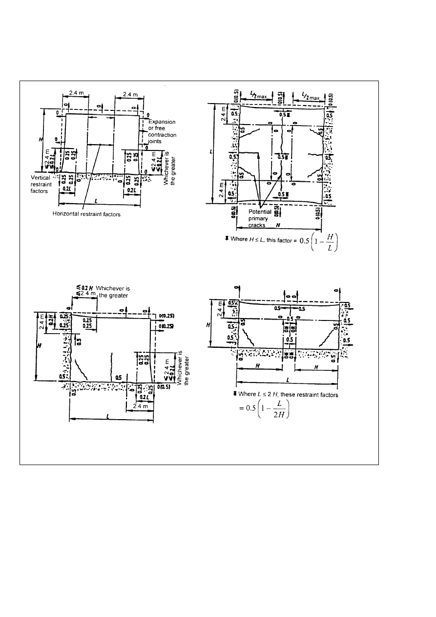
A.106.2 Assessment of restraint
(101) The restraint factors R
ax
and R
m
may be
calculated from a knowledge of the stiffnesses of the
element considered and the members attached to it.
Alternatively, practical axial restraint factors for
common situations may be taken from Table A.106.1
and Figure A.106.1. In many cases (e.g. a wall cast
onto a heavy preexisting base) it will be clear that
no significant curvature could occur and a moment
restraint factor R
m
of 1.0 will be appropriate.
Table A.106.1 Ð Restraint factors R
ax
and R
m
for central zones of walls shown in
Figure A.106.1a)
ratio L/H (see Fig.
A.106.1)
restraint factors
at base
restraint factors
at top
1
0.5
0
2
0.5
0
3
0.5
0.05
4
0.5
0.3
>8
0.5
0.5
Informative Appendix 107
Calculation of leakage through cracks in
elements retaining liquids
A.107.1 Equation for the prediction of leakage
(101) The leakage through a crack may be predicted
by Equation (A 107.1):
Q =
[m
3
/s]
(A 107.1)
w
eff
3
L
c
k
h
Dr
h
where
Q
the leakage in m
3
/s;
K
a coefficient depending on the surface
characteristics of the crack;
h
the dynamic viscosity of the liquid (kg/ms);
w
eff
the effective crack width (m);
L
c
the crack length (m);
Dr
pressure difference across the element (Pa);
h
the thickness of the element (m).
(102) The effective crack width, w
elf
, may be
obtained from the relation given below:
w
eff
= [2 (w
i
w
o
)
2
/(w
i
+ w
o
)]
î
(A 107.2)
where
w
o
the crack width on the outer face of the
member;
w
i
the crack width on the inner face of the
member.
The value of K may be taken as 1/50 for cracks with
no self-healing. For cracks in water with seif-heaiing
where w
eff
is # 0.2 mm, k may be assumed to reduce
from 1/50 towards 0 as the time approaches t = `.
Licensed copy:Heriot Watt University, 20/04/2004, Uncontrolled Copy, © BSI
Page 18
EN 1992-4:1998
BSI 08-2000
See Table A.106.1 for this central zone
a) Wall on base
b) Horizontal slab between right restraints
c) Sequential bay wall construction (with construction joints)
d) Alternate bay wall construction (with construction joints)
Figure A.106.1 Ð Restraint factors R
ax
and R
m
for central zones of walls
Licensed copy:Heriot Watt University, 20/04/2004, Uncontrolled Copy, © BSI

blank
Licensed copy:Heriot Watt University, 20/04/2004, Uncontrolled Copy, © BSI

DD ENV
1992-4:2000
BSI
389 Chiswick High Road
London
W4 4AL
|
|
|
|
|
|
|
|
|
|
|
|
|
|
|
|
|
|
|
|
|
|
|
|
|
|
|
|
|
|
|
|
|
|
|
|
|
|
|
|
|
|
|
|
|
|
|
|
|
|
|
|
|
|
|
|
|
|
|
|
|
|
|
|
|
|
|
|
|
|
|
|
|
|
|
|
|
|
|
|
|
|
|
|
|
|
|
|
|
|
|
|
|
|
|
|
|
|
|
|
|
|
|
|
|
|
|
|
|
|
|
|
|
|
|
|
|
|
|
|
|
|
|
|
|
|
|
BSI Ð British Standards Institution
BSI is the independent national body responsible for preparing British Standards. It
presents the UK view on standards in Europe and at the international level. It is
incorporated by Royal Charter.
Revisions
British Standards are updated by amendment or revision. Users of British Standards
should make sure that they possess the latest amendments or editions.
It is the constant aim of BSI to improve the quality of our products and services. We
would be grateful if anyone finding an inaccuracy or ambiguity while using this
British Standard would inform the Secretary of the technical committee responsible,
the identity of which can be found on the inside front cover. Tel: 020 8996 9000.
Fax: 020 8996 7400.
BSI offers members an individual updating service called PLUS which ensures that
subscribers automatically receive the latest editions of standards.
Buying standards
Orders for all BSI, international and foreign standards publications should be
addressed to Customer Services. Tel: 020 8996 9001. Fax: 020 8996 7001.
In response to orders for international standards, it is BSI policy to supply the BSI
implementation of those that have been published as British Standards, unless
otherwise requested.
Information on standards
BSI provides a wide range of information on national, European and international
standards through its Library and its Technical Help to Exporters Service. Various
BSI electronic information services are also available which give details on all its
products and services. Contact the Information Centre. Tel: 020 8996 7111.
Fax: 020 8996 7048.
Subscribing members of BSI are kept up to date with standards developments and
receive substantial discounts on the purchase price of standards. For details of
these and other benefits contact Membership Administration. Tel: 020 8996 7002.
Fax: 020 8996 7001.
Copyright
Copyright subsists in all BSI publications. BSI also holds the copyright, in the UK, of
the publications of the international standardization bodies. Except as permitted
under the Copyright, Designs and Patents Act 1988 no extract may be reproduced,
stored in a retrieval system or transmitted in any form or by any means ± electronic,
photocopying, recording or otherwise ± without prior written permission from BSI.
This does not preclude the free use, in the course of implementing the standard, of
necessary details such as symbols, and size, type or grade designations. If these
details are to be used for any other purpose than implementation then the prior
written permission of BSI must be obtained.
If permission is granted, the terms may include royalty payments or a licensing
agreement. Details and advice can be obtained from the Copyright Manager.
Tel: 020 8996 7070.
Licensed copy:Heriot Watt University, 20/04/2004, Uncontrolled Copy, © BSI
Document Outline
Wyszukiwarka
Podobne podstrony:
Eurocode 2 Design of concrete structures part4
Eurocode 2 Design of concrete structures Part 2
Eurocode 2 Design of concrete structures part1 2
Eurocode 2 Design of concrete structures Part 1 3
Eurocode 2 Design of concrete structures Part 2
Eurocode 2 Part 3 2006 UK NA Design of concrete structures Liquid retaining and containing struc
Eurocode 2 Part 1 1 2004 NA UK Design of concrete structures General rules and rules for buildin
Eurocode 2 Part 3 2006 Design of concrete structures Liquid retaining and containing structures
Eurocode 2 Part 2 2004 UK NA Design of concrete structures Concrete bridges Design and detailin
Eurocode 2Design of concrete structures Part 1 1
Eurocode 5 EN 1995 1 1 Design Of Timber Structures Part 1 1 General Rules
Eurocode 5 EN 1995 1 1 Design Of Timber Structures Part 1 1 General Rules
Eurocode 6 Part 1 2 1996 2005 Design of Masonry Structures General Rules Structural Fire Design
Eurocode 6 Part 2 1996 2006 Design of Masonry Structures Design Considerations, Selection of Mat
Eurocode 3 Part 1 7 2009 Design of Steel Structures Plated Structures Subject to Out of Plane Loa
więcej podobnych podstron