
DRAFT FOR DEVELOPMENT
DD ENV
1992-2:2001
Eurocode 2: Design of
concrete structures
Part 2. Concrete bridges
(together with United Kingdom
National Application Document)
ICS 91.080.40; 93.040
NO COPYING WITHOUT BSI PERMISSION EXCEPT AS PERMITTED BY COPYRIGHT LAW
Licensed copy:Heriot Watt University, 20/04/2004, Uncontrolled Copy, © BSI

DD ENV 1992-2:2001
This Draft for Development,
having been prepared under
the direction of the Sector
Board for Building and Civil
Engineering was published
under the authority of the
Standard Board and comes into
effect on 15 April 2001
BSI 04-2001
The following BSI references
relate to the work on this Draft
for Development:
Committee reference B/525/10
ISBN 0 580 33265 9
Committees responsible for this
Draft for Development
The preparation of this Draft for Development was entrusted by Technical
Committee B/525, Building and civil engineering structures, to Subcommittee
B/525/10, Bridges, upon which the following bodies were represented:
Association of Consulting Engineers
British Cement Association
British Construction Steelwork Association Ltd.
British Precast Concrete Federation Ltd.
British Railway Board
British Waterways Board
County Surveyors’ Society
Department of the Environment Transport and the Regions
(Highways Agency)
Institution of Civil Engineers
Institution of Structural Engineers
Steel Construction Institute
UK Steel Association
Welding Institute
Amendments issued since publication
Amd. No
Date
Comments
Licensed copy:Heriot Watt University, 20/04/2004, Uncontrolled Copy, © BSI

DD ENV 1992-2:2001
© BSI 04-2001
i
Contents
Committees responsible
Inside front cover
National foreword
ii
Text of National Application Document
iii
Text of ENV 1992-2
2
Licensed copy:Heriot Watt University, 20/04/2004, Uncontrolled Copy, © BSI

DD ENV 1992-2:2001
ii
© BSI 04-2001
National foreword
This Draft for Development was prepared by Subcommittee B/525/10 and is the
English language version of ENV 1992-2:1996 Eurocode 2: Design of concrete
structures — Part 2: Concrete bridges, as published by the European Committee
for Standardization (CEN). This Draft for Development also includes the United
Kingdom (UK) National Application Document (NAD) to be used with the ENV in
the design of buildings to be constructed in the UK.
ENV 1992-2 results from a programme of work sponsored by the European
Commission to make available a common set of rules for the structural and
geotechnical design of building and civil engineering works.
This publication should not be regarded as a British Standard.
An ENV is made available for provisional application, but does not have the
status of a European Standard. The aim is to use the experience gained to modify
the ENV so that it can be adopted as a European Standard. The publication of this
ENV and its National Application Document should be considered to supersede
any reference to a British Standard in previous DD ENV Eurocodes concerning
the subject covered by these documents.
The values for certain parameters in the ENV Eurocodes may be set by individual
CEN Members so as to meet the requirements of national regulations. These
parameters are designated by |_| in the ENV.
During the ENV period of validity, reference should be made to the supporting
documents listed in the National Application Document (NAD).
The purpose of the NAD is to provide essential information, particularly in
relation to safety, to enable the ENV to be used for buildings constructed in the
UK and the NAD takes precedence over corresponding provisions of the ENV.
Users of this document are invited to comment on its technical content, ease of
use and any ambiguities or anomalies. These comments will be taken into account
when preparing the UK national response to CEN on the question of whether the
ENV can be converted to an EN.
Comments should be sent in writing to the Secretary of Subcommittee B/525/10,
BSI, 389 Chiswick High Road, London W4 4AL, quoting the document reference,
the relevant clause and, where possible, a proposed revision within two years of
the issue of this document.
This document does not puport to include all the necessary provisions of a
contract. Users of this document are responsible for its correct application.
Summary of pages
This document comprises a front cover, an inside front cover, pages i to xxiv, the
ENV title page, pages 2 to 45 and a back cover.
The BSI copyright notice displayed in this document indicates when the
document was last issued.
Licensed copy:Heriot Watt University, 20/04/2004, Uncontrolled Copy, © BSI

DD ENV 1992-2:2001
© BSI 04-2001
iii
National Application
Document
for use in the UK with
ENV 1992-2:1996
Licensed copy:Heriot Watt University, 20/04/2004, Uncontrolled Copy, © BSI

DD ENV 1992-2:2001
iv
© BSI 04-2001
Contents of
National Application Document
Introduction
1
Scope
v
2
Normative references
v
3
Partial factors, combination factors and other values
v
4
Loading documents
vii
5
Reference standards
viii
6
Additional recommendations
x
Bibliography
xxii
Table 1 — Values to be used in referenced clauses instead of boxed values
vi
Table 2a) — References — References in ENV 1992-2 to other publications
viii
Table 2b) — References — References in ENV 1992-1-1 to other publications
ix
Table 2c) — References — References in ENV 1992-1-3 for precast concrete bridges to other
publications
x
Table 3 — Exposure classes related to environmental conditions
xi
Table 4 — Nominal cover requirements for normal weight concrete
xii
Table 5 — Effective height, l
o
, for columns
xv
Table 6a) — Limiting stress ranges (N/mm
2
) — Longitudinal bending for unwelded
reinforcing bars in road bridges
xviii
Table 6b) — Limited stress ranges (N/mm
2
) — Transverse bending for unwelded
reinforcing bars in road bridges
xviii
Table 4.121 — Maximum bar spacing for high bond bars
xx
Table 7 — Minimum diameters of mandrels
xx
Licensed copy:Heriot Watt University, 20/04/2004, Uncontrolled Copy, © BSI

DD ENV 1992-2:2001
© BSI 04-2001
v
Introduction
This National Application Document (NAD) has been prepared under the direction of the Building and
Civil Engineering Sector Committee. It has been developed from:
a) a textual examination of ENV 1992-2:1996 and ENV 1992-1-1:1991, ENV 1992-1-3:1994,
ENV 1992-1-4:1994, ENV 1992-1-5:1994 and ENV 1992-1-6:1994;
b) a parametric calibration examination against BS 5400-4, supporting standards and test data;
c) trial calculations.
1 Scope
This NAD provides information to enable ENV 1992-2:1996 (hereafter referred to as EC2-2) to be used
with ENV 1992-1-1:1991, ENV 1992-1-3:1994, ENV 1992-1-4:1994, ENV 1992-1-5:1994 and
ENV 1992-1-6:1994, as qualified by their respective NADs, for the design and construction of bridges in
the UK.
2 Normative references
The following normative documents contain provisions, which, through reference in this text, constitute
provisions of this National Application Document. For dated references, subsequent amendments to, or
revisions of, any of these publications do not apply. For undated references, the latest editions of the
publication referred to applies.
Standards publications
BS 5400-4, Steel, concrete and composite bridges — Code of practice for design of concrete bridges.
ENV 1991-3:1994, Eurocode 1: Basis of design and actions on structures — Part 3: Traffic loads on bridges.
ENV 1992-1-1:1991, Eurocode 2: Design of concrete structures — Part 1-1: General rules and rules for
buildings.
ENV 1992-1-3:1994, Eurocode 2: Design of concrete structures — Part 1-3: General rules — Precast concrete
elements and structures.
ENV 1992-1-4:1994, Eurocode 2: Design of concrete structures — Part 1-4: General rules — Lightweight
aggregate concrete with closed structure.
ENV 1992-1-5:1994, Eurocode 2: Design of concrete structures — Part 1-5: Unbonded and external
prestressing tendons.
ENV 1992-1-6:1994, Eurocode 2: Design of concrete structures — Part 1-6: General rules — Plain concrete
structures.
Other documents
GREAT BRITAIN. HIGHWAYS AGENCY. Design manual for roads and bridges. Vol. 1. Highway
structures: approval procedures and general design — Section 3: General design — Loads for highway
bridges. Publication no. BD 37/88. London: The Stationery Office, 1994.
GREAT BRITAIN. HIGHWAYS AGENCY. Manual of Contract Documents for Highway Works —
Volume 1: Specification for Highway Works. London: The Stationery Office, 1998.
Licensed copy:Heriot Watt University, 20/04/2004, Uncontrolled Copy, © BSI

DD ENV 1992-2:2001
vi
© BSI 04-2001
3 Partial factors, combination factors and other values
The partial factors, combination factors and other values are as follows.
a) The values for combination factors (Ò) should be those given in Table 3 and Table 4 of the NAD for use
with ENV 1991-3:1994.
b) The values for partial factors should be those given in EC2-2, except as modified by the UK NADs to
the various parts of ENV 1992-1-1.
c) ENV 1992-1-1:1991, 2.5.3.5.5 (5) should not be modified as indicated in Table 3 of its NAD.
d) Other values should be those given in EC2-2 except for those given in Table 1 of this NAD.
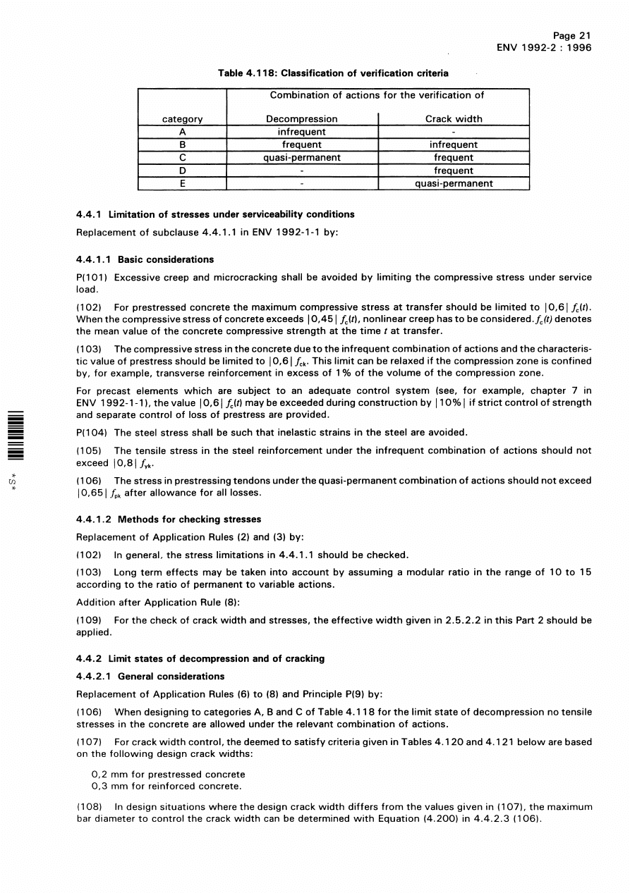
Table 1 — Values to be used in referenced clauses instead of boxed values
Reference in
ENV 1992-1-1
Reference in
ENV 1992-1-3
Reference in
ENV 1992-2
Definition
UK values
3.2.5.1 (5)
Minimum shear strength of
welds
25 % of the tensile
strength of the bar
4.1.3.3 (8)
Allowance for tolerance %h in
cover for precast elements
%h = 5 mm
4.1.3.3 (8)
Allowance for tolerance %h
in cover for in situ concrete
%h = 5 mm
4.2.1.3.3 (12)
Reduction factor µ to take
account of the effects of
long-term loading on
maximum compressive stress
(compression zone decreasing
in width)
0.85
4.2.3.4.1 (2)
Ratio of long-term relaxation
to 1 000 h relaxation
2
4.3.2.4.4 (1)
Limit to cotÚ in the variable
strut inclination method for
beams with constant
reinforcement
0.5 < cotÚ < 2.0
4.3.3.1 (6)
Limits to cotÚ in torsion
calculation
0.5 < cotÚ < 2.0
4.3.4.5.2 (1)
V
rd2
2.0 [see also 6.3i) of this
NAD]
4.3.7.5 (101)
Fatigue stress range
See 6.3c) of this NAD
4.4.2.2.1 (103)
Maximum bar spacing
300
4.5.2 (103)
Limit to average bearing
stress
0.8f
cd
Table 5.1
Minimum diameter of
mandrels
See Table 7 of this NAD
Licensed copy:Heriot Watt University, 20/04/2004, Uncontrolled Copy, © BSI

DD ENV 1992-2:2001
© BSI 04-2001
vii
Table 1 — Values to be used in referenced clauses instead of boxed values (continued)
4 Loading documents
The loading documents to be used are:
Reference in
ENV 1992-1-1
Reference in
ENV 1992-1-3
Reference in
ENV 1992-2
Definition
UK values
5.2.4.1.3 (1)
Limiting value of the clear
spacing a, above which µ
1
may take a value of 1.0 for
compression and 1.4 for
tension
6Ì
Limiting value of b to lapped
bar above which µ
1
may take
a value of 1.0 for compression
and 1.4 for tension
2Ì
5.2.5 (3)
Extent of bar beyond bend in
link
4Ì instead of 5Ì
8Ì instead of 10Ì
5.4.1.2.2 (4)
Factor by which minimum
spacing should be reduced
under defined circumstances 0.67
In item ii), bar size near lap
above which spacing of
transverse steel should be
reduced
20 mm
5.4.3.2.1 (4)
Maximum bar spacing in
slab
300 mm
5.4.3.3 (2)
Minimum shear as a
percentage of the total for
beams
100 %
6.2.2 (1)
Tolerances
See 5.5 of this NAD
ENV 1991-3
for traffic loads;
BD 37/88
for all other loads.
Licensed copy:Heriot Watt University, 20/04/2004, Uncontrolled Copy, © BSI

DD ENV 1992-2:2001
viii
© BSI 04-2001
5 Reference standards
Standards including materials specifications and standards for construction are listed for reference in
Table 2a), Table 2b) and Table 2c) of this NAD.
Table 2a) — References — References in ENV 1992-2 to other publications
Reference in
ENV 1992-2
Document referred to
Document title or subject area UK document
Highways Agency
document
1.1.2 P(104)
Eurocode 1
Basis of design and actions
on structures
BS 5400-1
BS 5400-2
a
BD 15/92 [1]
BD 37/88
1.1.2 P(104)
Eurocode 8
Design of structures in
seismic regions
—
—
1.1.2 (105)
Eurocode 1-1
Basis of design
BS 5400-1
BD 15/92 [1]
1.1.2 (105)
Eurocode 1-2-1
Actions on structures:
densities, self-weight and
imposed loads
BS 5400-2
a
BD 37/88
1.1.2 (105)
Eurocode 1-2-4
Actions on structures:
wind actions
BS 5400-2
a
BD 37/88
1.1.2 (105)
Eurocode 1-2-5
Actions on structures:
thermal actions
BS 5400-2
a
BD 37/88
1.1.2 (105)
Eurocode 2-1-2
Structural fire design
—
—
1.1.2 (105)
Eurocode 2-1-4
The use of lightweight
aggregate concrete
BS 5400-4
BD 24/92 [2]
1.1.2 (105)
Eurocode 2-1-6
Plain concrete
BS 5400-4
BD 24/92 [2]
1.1.2 (105)
Eurocode 2-3
Concrete foundations
BS 8004
BD 32/88 [3]
1.1.2 (105)
Eurocode 7-1
Geotechnical design
BS 1377
BS 8004
BS 5930
BD 32/88 [3]
BD 30/87 [4]
1.1.2 (105)
Eurocode 8-2
Earthquake resistant
design of structures
—
—
1.4.1 P(104)
ENV 1991-1
Basis of design
BS 5400-1
BD 15/92 [1]
A107
prEN 10138
Prestressing steel
BS 4486
BS 5896
Specification for
Highway Works
A107.1 (103)
ENV 1992-3
Types of stay cable
—
—
A107.4 (107)
ISO 161-1, ISO 3607
b
or other relevant
standards
Specification for high
density polyethylene
(HDPE)
—
—
a
This has been partially replaced by BS 5400-9.1:1983 and BS 5400-9.2:1983.
b
This has now been replaced by ISO 11922-1 and ISO 11922-2.
Licensed copy:Heriot Watt University, 20/04/2004, Uncontrolled Copy, © BSI

DD ENV 1992-2:2001
© BSI 04-2001
ix
Table 2b) — References — References in ENV 1992-1-1 to other publications
Reference in
ENV 1992-1-1
Document referred to
Document title or subject area
UK document
Highways Agency
document
1.1.1 P(4)
Eurocode 8
Design of structures in
seismic regions
—
—
1.1.1 P(5)
Eurocode 1
Basis of design and actions
on structures
BS 5400-1
BS 5400-2
a
BD 15/92 [1]
BD 37/88
3.2, 3.3
and 3.4
ENV 10080 and
relevant standards
Reinforcing steel
BS 4449
BS 4482
BS 4483
—
prEN 10138 and
relevant standards
Prestressing steel
BS 4486
BS 5896
—
3.4
Relevant standards
European Approval
Documents
Anchorages
BS 4447
—
4.1.2.3 (3)
ISO/DP 9690
ENV 206
Classification of
environmental conditions
for concrete structures
—
—
4.2.3.4.1
Relevant standards
Relaxation of prestressing
steel
BS 4486
BS 5896
—
6.3.2.2
Appropriate national
or international
documents
Specification of finishes
BS 5400-7
Specification for
Highway Works
6.3.3.1 P(1)
Relevant Euronorms
or CEN, ISO or
national standards,
National Building
Regulations Control
Authority
Requirements for
reinforcing steel
BS 4449
BS 4482
BS 4483
BS 5400-7
Specification for
Highway Works
6.3.3.2 P(3)
Appropriate
international or
national standards
Cutting and bending of
reinforcement
BS 4466
Specification for
Highway Works
6.3.3.3 P(3)
International or
national standards
Welding of reinforcement
BS 7123
BA 40/93 [5]
Specification for
Highway Works
6.3.3.3 P(4)
Relevant standards
Fatigue requirements for
welding of reinforcement
BS 5400-7
BS 5400-10
BD 9/81 [6],
BA 40/93 [5]
6.3.3.3 P(5)
International or
national standards
Production and checking of
welded connections
BS 7123
BA 40/93
Specification for
Highway Works
6.3.3.4 (3)
Standards or
approval documents
Mechanical connectors
BS 5400-4
BD 24/92
Specification for
Highway Works
a
This has been partially replaced by BS 5400-9.1:1983 and BS 5400-9.2:1983.
Licensed copy:Heriot Watt University, 20/04/2004, Uncontrolled Copy, © BSI

DD ENV 1992-2:2001
x
© BSI 04-2001
Table 2b) — References — References in ENV 1992-1-1 to other publications (continued)
Table 2c) — References — References in ENV 1992-1-3 for precast concrete bridges to other
publications
6 Additional recommendations
6.1 Chapter 1. Introduction
a) Clause 1.1.2 P(101)
All references to ENV 1992-1-1 in EC2-2 shall be interpreted as being to ENV 1992-1-1 as qualified by
its UK NAD.
b) Clause 1.1.2 (105)
All references to any ENV shall be interpreted as being to that ENV as qualified by its UK NAD.
6.2 Chapter 3. Material properties
a) Clause 2.5.4.2 (4)
Clause 2.5.4.2 (104) of ENV 1992-1-3:1994 is applicable only to pretensioning.
Reference in
ENV 1992-1-1
Document referred to
Document title or subject area UK document
Highways Agency
document
6.3.4.1
Relevant Euronorms or
CEN, ISO or national
standards, National
Building Regulations
Control Authority
Requirements for
prestressing steel
BS 4486
BS 5896
Specification for
Highway Works
6.3.4.3
Standards or approval
documents
Devices for jointing,
anchorage and coupling of
tendons
BS 4447
—
6.3.4.6.2 P(4)
EN 447
Types of cement for
grouting
Concrete
Society
Technical
Report
No. 47 [7]
—
7.5
CEC or National
Administrative
Procedures
Control of design
—
BD 2/89 [8]
7.6.5
Relevant technical
documents
All other structural
materials
—
Specification for
Highway Works
Reference in
ENV 1992-1-3
Document referred to
Document title or subject area UK document
Highways Agency
document
6.2.1 (104)
Relevant CEN product
standards
Tolerances of construction
and workmanship
BS 5400-7
Specification for
Highway Works
6.3.5 (101)
Relevant CEN product
and other standards
Construction and
workmanship of precast
elements and structures
BS 5400-4
BS 5400-7
BD 24/92
Specification for
Highway Works
Licensed copy:Heriot Watt University, 20/04/2004, Uncontrolled Copy, © BSI

DD ENV 1992-2:2001
© BSI 04-2001
xi
6.3 Chapter 4. Section and member design
a) Clause 4.1.3.3 (6)
For the relevant exposure class defined in Table 3 of this NAD, the nominal concrete cover to all
reinforcement including links and stirrups should not be less than the appropriate values given in
Table 4 of this NAD. However, for pretensioned precast units the values in Table 4 of this NAD should
be reduced by 10 mm. Where de-icing agents are used in a region, structures shall be classified as
exposure Class 3 unless it can be guaranteed that the type of de-icing agent to which the structure will
be exposed will have no deleterious effect on the reinforcement. Bridges over non-electrified railways
shall be classified as exposure Class 5b and the nominal cover to reinforcing bars should not be less than
45 mm.
Table 3 — Exposure classes related to environmental conditions
Exposure class
Environment
Examples
1 Moderate
Concrete surfaces above ground
level and fully sheltered against
all of the following:
Surfaces protected by waterproofing or
by permanent formwork.
— rain;
Interior surface of pedestrian subways,
voided superstructures or cellular
abutments.
— de-icing salts;
— sea water spray.
Concrete surfaces permanently
saturated by water with a
pH > 4.5.
Concrete permanently under water.
2 Severe
2a Without
frost
Concrete surfaces exposed to
driving rain.
Concrete surfaces exposed to
alternative wetting and drying.
Wall and structure supports remote
from the carraigeway.
Bridge deck soffits. Buried parts of
structures.
2b With frost As 2a but also exposed to
freezing and thawing
As 2a.
3 Very severe
Concrete surfaces directly
affected by de-icing salts.
Walls and structures within 10 m of
the carriageway, parapet edge beams
and buried structures less than 1 m
below carriageway level.
4 Extreme
4a Without
frost
Concrete surfaces in saturated
salt air.
Concrete adjacent to the sea.
Concrete surfaces exposed to
abrasive action by sea water.
Marine structures.
Concrete surfaces exposed to
water with a pH k4.5.
Parts of structure in contact with
moorland water.
4b With frost As 4a but also exposed to
freezing and thawing.
As 4a above.
5 Aggressive
a
5a
Concrete surfaces exposed to a
slightly aggressive chemical
environment.
Concrete in an aggressive industrial
atmosphere. Parts of structure in
contact with contaminated ground.
5b
Concrete surfaces exposed to a
moderately aggressive chemical
environment.
Parts of structure in contact with
contaminated ground.
5c
Concrete surfaces exposed to a
highly aggressive chemical
environment.
Parts of structure in contact with
contaminated ground.
a
Chemically aggressive environments are classified in ISO/DP9690. The following equivalent exposure conditions may be
assumed:
Exposure class 5a: ISO classification A1G, A1L, A1S;
Exposure class 5b: ISO classification A2G, A2L, A2S;
Exposure class 5c: ISO classification A3G, A3L, A3S.
Licensed copy:Heriot Watt University, 20/04/2004, Uncontrolled Copy, © BSI

DD ENV 1992-2:2001
xii
© BSI 04-2001
Table 4 — Nominal cover requirements for normal weight concrete
a
b) Clause 4.2.1.3.3 (11)
µ should be taken as 0.85 for both short-term and long-term effects.
c) Clause 4.2.3.5.6
Where a pre-tensioned tendon or group of tendons is enclosed by transverse reinforcement with an area
of at least 1 000 mm
2
/m 
b
may be taken as 50 % of the appropriate value given in Table 4.7 for all strand
with areas up to 225 mm
2
.
d) Clause 4.3.2.2 (11)
In addition:
d) in the case of a pile cap, enhancement should be applied only to those portions of the section where
the flexural reinforcement is fully anchored by passing across the head of a pile.
Exposure class
Location
Nominal cover
mm
Concrete grade
C20/25
C25/30
C30/37
C40/50
and above
1
3
55
45
40
35
2
2a
2
b
80
80
80
3
b
55
45
40
2b
2
b
80
a
80
80
3
b
55
a
45
40
3
1
b
c
85
a
85
2
b
c
80
a
80
3
b
c
60
a
50
4
4a
1
b
b
85
85
2
b
b
80
80
3
b
b
75
65
4b
1
b
b
85
a
85
2
b
b
80
a
80
3
b
b
75
a
65
5
5a
5b
5c
This exposure can occur alone or in combination with
the above classes. In selecting an appropriate cover the
designer should consider other relevant exposure
classes, such as cement content, type of cement,
water:cement ratio and the use of protective
membranes.
Location:
1 — tendons in slabs where the upper surface is directly exposed to de-icing agents
(i.e. no protective membrane);
2 — cast against an earth face;
3 — other locations.
NOTE For pretensioned precast units the tabulated values may be reduced by 10 mm.
a
Air entrained concrete should be specified.
b
Concrete grade not permitted.
c
Parapet beams only, nominal cover = 70 mm.
Licensed copy:Heriot Watt University, 20/04/2004, Uncontrolled Copy, © BSI

DD ENV 1992-2:2001
© BSI 04-2001
xiii
e) Clause 4.3.2.3 (1)
Equation (4.18)
Replace Equation (4.18) with:
V
Rd1
= *0.21k (100Ô
1
f
ck
)
0.33
+ 0.15Ö
cp
4 b
w
d
Change the definitions as follows:
Delete:
E
Rd
Add:
k = (500/d)
0.25
)
Ô
1
= A
s1
/ b
w
d k |0.03|
A
s1
= the area of tension reinforcement extending not less than d beyond the section considered
Other terms are as defined previously.
Delete Table 4.8.
f) Clause 4.3.2.4.3 (1)
The equation should be replaced as follows:
Equation (4.22):
V
Rd3
= V
wd
+ V
cd
– 0.4
g) Clause 4.3.2.5 (4)
Delete:
E
Rd
is taken from Table 4.8 in 4.8.2.3
and insert:
E
Rd
is given in the following Table 4.8.
¾
c
= 1.5 for different concrete strengths
h) Clause 4.3.4.1 (9)
Does not apply.
i) Clause 4.3.4.2.1 (1)
Items 1) and 2) should be replaced with:
1) In the case of a rectangular loaded area having a perimeter greater than 11d and/or a ratio of length
to breadth greater than 2.0, the critical perimeter according to Figure 4.17 only should be taken into
account, in the absence of a more detailed analysis.
f
ck
12.0
16.0
20.0
25.0
30.0
35.0
40.0
45.0
50.0
E
Rd
0.18
0.22
0.26
0.30
0.34
0.37
0.41
0.44
0.48
Licensed copy:Heriot Watt University, 20/04/2004, Uncontrolled Copy, © BSI

DD ENV 1992-2:2001
xiv
© BSI 04-2001
j) Clause 4.3.4.2.2 (1)
If a part of a perimeter cannot, physically, extend 1.5d from the boundary of the loaded area, then the
part perimeter shall be taken as far from the loaded areas as is physically possible and the value of V
Rd1
,
given in 4.3.4.5.1 (1), for that part may be increased by a factor 1.5d/x, where x is the distance from the
boundary of the loaded area to the perimeter actually considered.
k) Clause 4.3.4.5.1
Replace Equation (4.56) and the definitions with the following:
where
k = (500/d)
0.25
;
Ô
1
=
;
Ô
1x
Ô
1y
are ratios in the x and y directions calculated for a width equal to the side dimension of the
column (or loaded area) plus 3d to either side of it (or to slab edge if it is closer);
d = (d
x
+ d
y
)/2;
d
x
and d
y
are the effective depths of the slab at the points of intersection between the design failure
surface and the longitudinal reinforcement, in the x and y direction respectively.
l) Clause 4.3.4.5.1 (2)
The upper limit of 0.015 applies to
and not to Ô
1
.
m) Clause 4.3.4.5.2 (1)
In Equation (4.57), in addition to the limitation on V
Rd2
given in Table 1 of this NAD the shear stress at
the perimeter of the coloumn should not exceed 0.9
.
Equation (4.58) is applicable where V
Rd3
k 1.6V
Rd1
.
Where 1.6V
Rd1
< V
Rd3
k 2.0V
Rd1
, Equation (4.58a) should be used:
V
Rd3
= 1.4V
Rd1
+
/ u
(4.58a)
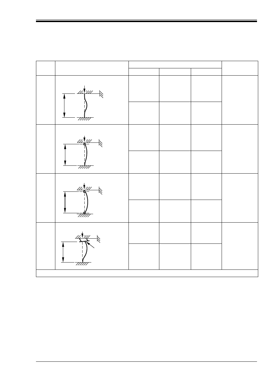
n) Clause 4.3.5.3.5 P(101)
The effective height, l
o
, of a column may be determined using Table 5 of this NAD where l
col
is the clear
height between end restraints.
The values given in Table 5 are based on the following assumptions:
a) rotational restraint is at least 4E
cm
I
col
/l
col
for cases 1, 2 and 4 to 6 and 8E
cm
I
col
/l
col
for case 7;
b) lateral and rotational rigidity of elastomeric bearings are zero.
Where a more accurate evaluation of the effective height is required or where the end stiffness values are
less than those values given in a), the effective heights should be derived from first principles.
The accommodation of movements and the method of articulation chosen for the bridge will influence the
degree of restraint developed for columns. These factors should be assessed as accurately as possible
using engineering principles based on elastic theory and taking into account all relevant factors such as
foundation flexibility, type of bearings, articulation system, etc.
V
Rd1 =
*0.21k(100Ô
1
f
ck
)
0.33
+ 0.15Ö
cp
4 b
w
d
(4.56)
Ô
1x
Ô
1y
Ô
1x
Ô
1y
f
ck
0.3 A
sw
f
ya
µ
sin
å
(
)
Licensed copy:Heriot Watt University, 20/04/2004, Uncontrolled Copy, © BSI
DD ENV 1992-2:2001
© BSI 04-2001
xv
Table 5 — Effective height, l
o
, for columns
Case
Idealized column and buckling mode
Restraints
Effective height,
l
c
Location
Position
Rotation
1
Top
Full
Full
a
0.70 l
col
Bottom
Full
Full
a
2
Top
Full
None
0.85 l
col
Bottom
Full
Full
a
3
Top
Full
None
1.0 l
col
Bottom
Full
None
4
Top
None
a
None
a
1.3 l
col
Bottom
Full
Full
a
a
Assumed value [see 6.3n)].
l
col
l
col
l
col
l
col
Elastomeric
bearing
Licensed copy:Heriot Watt University, 20/04/2004, Uncontrolled Copy, © BSI
DD ENV 1992-2:2001
xvi
© BSI 04-2001
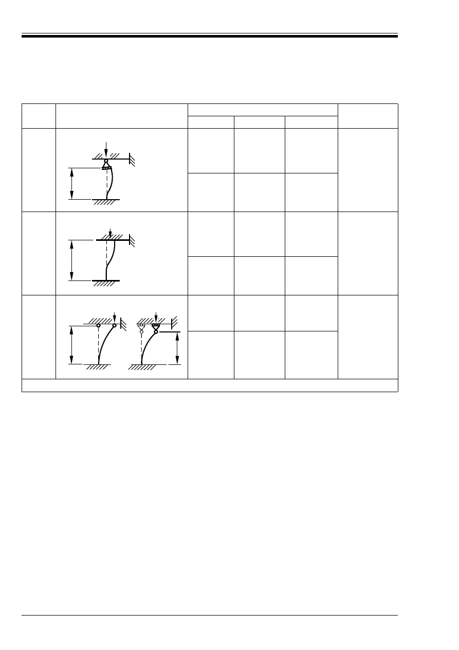
Table 5 — Effective height, l
o
, for columns (continued)
Case
Idealized column and buckling mode
Restraints
Effective height,
l
c
Location
Position
Rotation
5
Top
None
None
1.4 l
col
Bottom
Full
Full
a
6
Top
None
Full
a
1.5 l
col
Bottom
Full
Full
a
7
Top
None
None
2.3 l
col
Bottom
Full
Full
a
a
Assumed value [see 6.3n)].
l
col
l
col
l
col
l
col
or
Licensed copy:Heriot Watt University, 20/04/2004, Uncontrolled Copy, © BSI

DD ENV 1992-2:2001
© BSI 04-2001
xvii
o) Clause 4.3.5.6
Notwithstanding the references to buildings in clause 4.3.5.6, it should be assumed that this clause is
applicable also to bridge structures.
p) Clause 4.3.5.6.4 (4)
When Equation (4.72) is used to calculate the curvature 1/r, then interaction of biaxial bending should
be considered using:
k 1.0
where
However, when the curvature is calculated using a non-linear analysis in each of the x and y directions,
µ
n
may be assumed to be 1.0.
q) Clause 4.3.5.7 (2)
The second of Equations (4.77) should be replaced with:
l
ot
<250 b
2
/d
r) Clause 4.3.7.1 (102)
When applying b) to railway bridges the depth of ballast should not be included in assessing the depth
of earth cover.
In addition to the situations listed in 4.3.7.1 (102), a fatigue verification for road bridges is not generally
necessary for the local effects of wheel loads applied directly to a slab spanning between beams or webs
provided that:
1) the clear span to overall depth ratio of the slab does not exceed 18;
2) the slab acts compositely with its supporting beams or webs;
3) either:
i) the slab also acts compositely with transverse diaphragms; or
ii) the width of the slab perpendicular to its span exceeds three times its clear span.
s) Clause 4.3.7.5 (101)
For road bridges, replace |70|N/mm
2
with the appropriate value from Table 6a) and Table 6b) of this
NAD. It is emphasized that the fatigue resistance of welded bars shall be checked using 4.3.7.5 (102).
NOTE Table 6b) need only be applied to those slabs that do not conform to the criteria in 6.3r) of this NAD.
M
x
and M
y
are the moments about the major x–x axis and minor y–y axis respectively due to
ultimate loads;
M
Rdx
is the ultimate moment capacity about the major x–x axis assuming an ultimate axial
load capacity, N
ud
, not less than the value of the ultimate axial load, N;
M
Rdy
is the ultimate moment capacity about the minor y–y axis assuming an ultimate axial
load capacity, N
ud
, not less than the value of the ultimate axial load, N;
µ
n
= 0.667 + 1.67 N/N
ud
U1.0 and k2.0.
M
x
M
Rdx
--------------
è
ø
æ
ö
µ
n
M
y
M
Rdy
--------------
è
ø
æ
ö
µ
n
+
Licensed copy:Heriot Watt University, 20/04/2004, Uncontrolled Copy, © BSI

DD ENV 1992-2:2001
xviii
© BSI 04-2001
Table 6a) — Limiting stress ranges (N/mm
2
) — Longitudinal bending for unwelded reinforcing
bars in road bridges
Table 6b) — Limiting stress ranges (N/mm
2
) — Transverse bending for unwelded reinforcing
bars in road bridges
t) Clause 4.3.7.5 (105)
In line 1 replace “P(103)” with “P(104)”.
u) Clause 4.3.7.6
It is not necessary to apply 4.3.7.6, if only prestressing steel is present at the section under consideration.
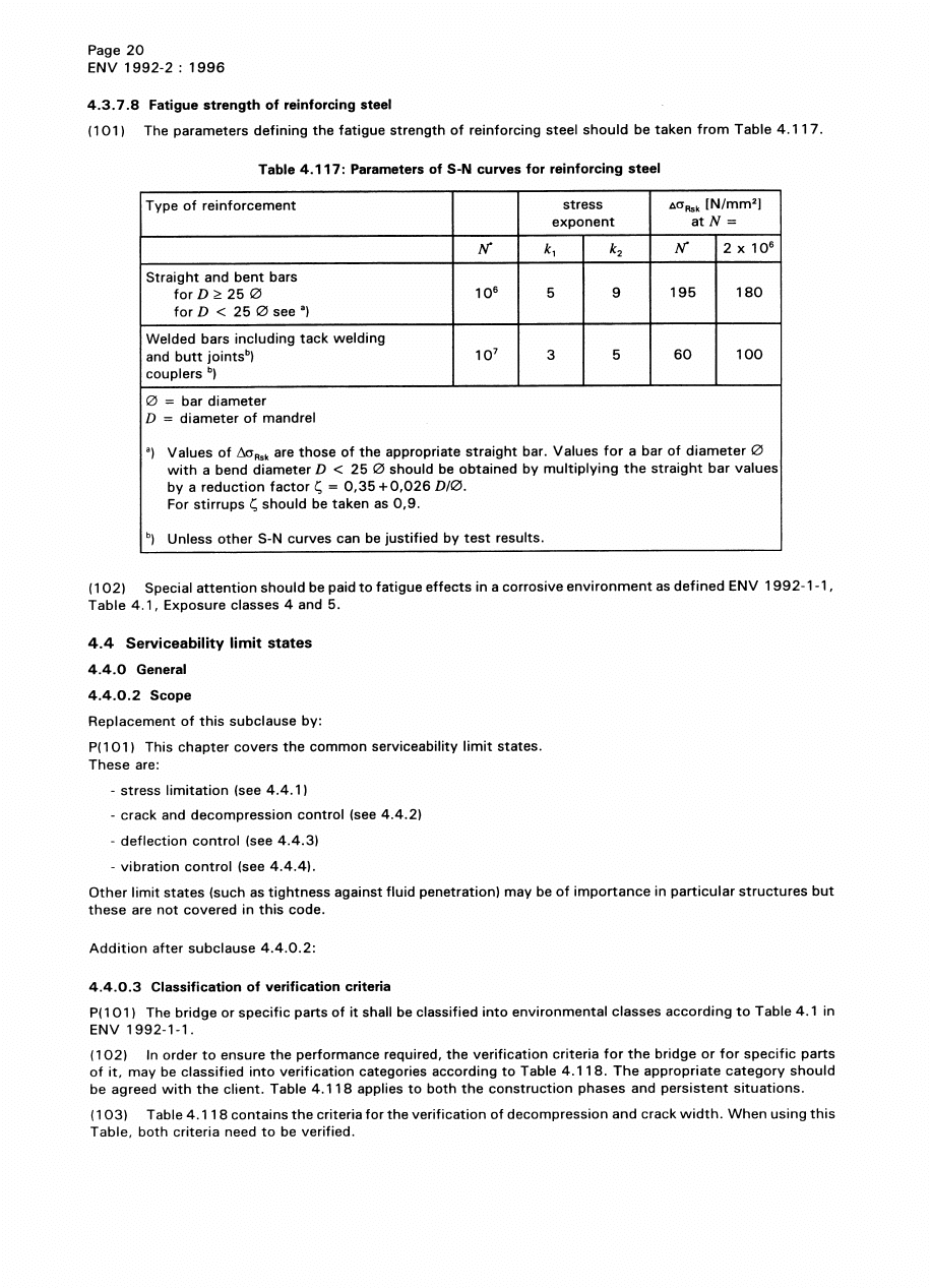
v) Clause 4.3.7.8
In Table 4.117, the values of %B
Rsk
for straight and bent bars of 195 N/mm
2
and 180 N/mm
2
, respectively,
should be reduced to 162 N/mm
2
and 150 N/mm
2
, respectively, for bars with a diameter greater than
16 mm.
Welds in reinforcing steel, including tack welds, should not be used in bridges carrying rail traffic
without prior approval of the relevant authority.
Welds in reinforcing steel should not be used in a deck slab spanning between longitudinal and/or
transverse members and subjected to the effect of concentrated wheel loads in a traffic lane. Lap welding
should not be used to connect reinforcing bars subjected to fatigue loading.
w) Clause 4.4.0.3 (102)
In the case of continuous bridges consisting of precast pretensioned beams with their ends embedded in
in-situ concrete crossheads at the supports, verification criterion B should be adopted for the embedded
lengths of the beams during the construction phase.
x) Clause 4.4.2.1 P(109)
Replace the existing clause with the following:
“For design crack width, members prestressed with permanently unbonded tendons without bonded
tendons may be treated as ordinary reinforced concrete members.”
y) Clause 4.4.2.2.1 P(101)
Replace the existing clause with the following:
“For reasons of durability and appearance of the concrete a minimum reinforcement area shall be
provided in reinforced or prestressed bridge structures in order to prevent wide single cracks due to
imposed deformations not considered in the design calculations, self-equilibrating stresses or
distribution of prestress.”
Span
Adjacent spans loaded
Alternate spans loaded
Bars k 16 mm Ì
Bars > 16 mm Ì
Bars k 16 mm Ì
Bars > 16 mm Ì
m
<3.5
150
115
210
160
3.5 to 5
125
95
175
135
5 to 10
110
85
175
135
10 to 20
110
85
140
110
20 to 100
90
70
110
85
100 to 200
115
90
135
105
>200
190
145
200
155
Span
Bars k 16 mm Ì
Bars > 16 mm Ì
mm
<3.5
210
160
3.5 to 5
120
90
5 to 10
70
55
Licensed copy:Heriot Watt University, 20/04/2004, Uncontrolled Copy, © BSI

DD ENV 1992-2:2001
© BSI 04-2001
xix
z) Clause 4.4.2.2.2 (101)
Replace the existing clause with the following:
“The minimum reinforcement area according to Equation (4.19.4) should be placed in sections where,
under the infrequent combination of actions, the concrete stresses are tensile or less than 1 N/mm
2
compressive. For box girders and I-beams the web and flanges may be treated separately for this
purpose.”
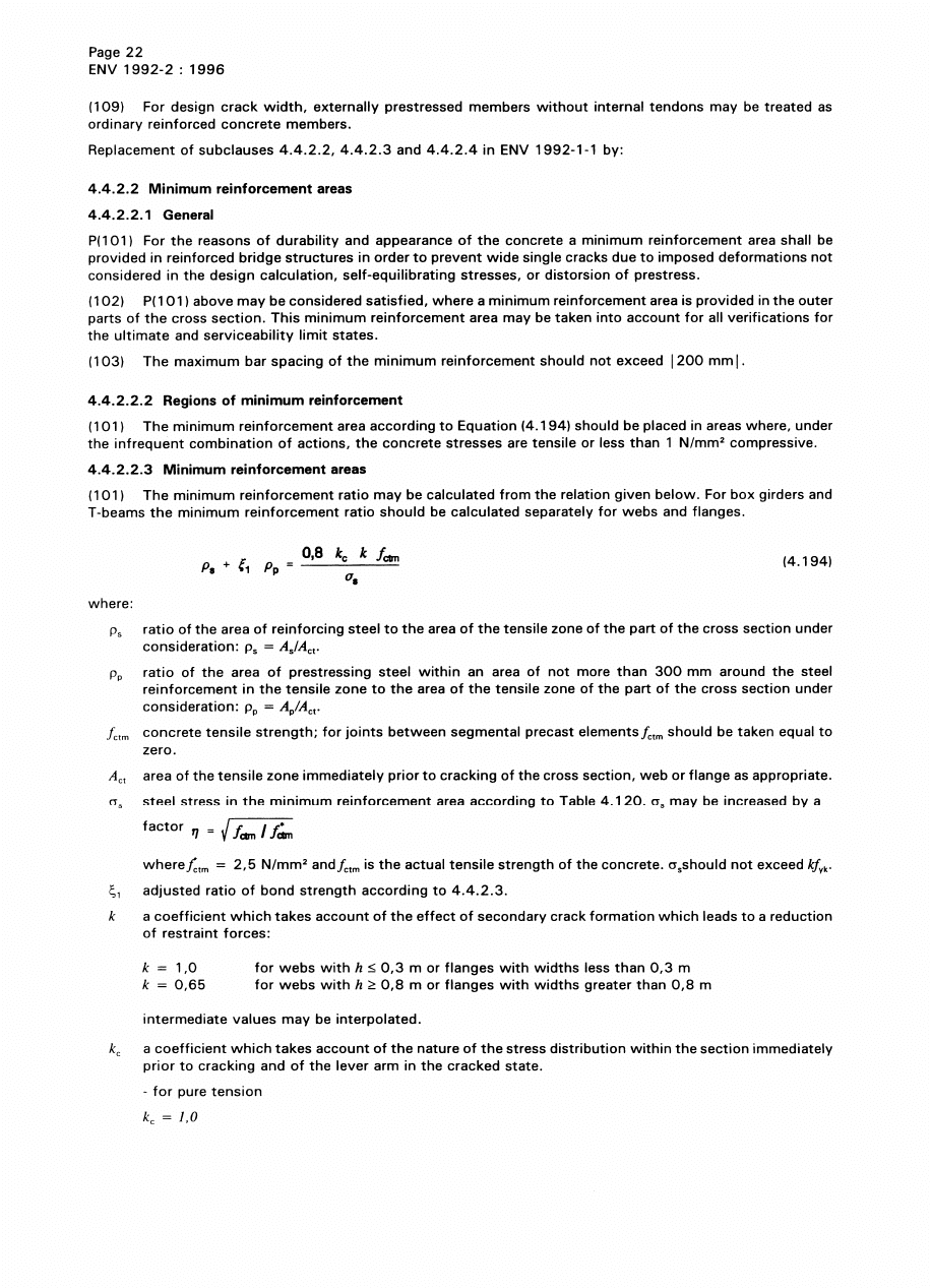
aa) Clause 4.4.2.2.3 (101)
In the definition of Ô
p
the words, “within an area of not more than 300 mm around the ordinary
reinforcement” should be deleted.
bb) Clause 4.4.2.2.3 (101)
Replace definitions of A
ct
, Ö
s
, k, N
sd
with the following:
cc) Clause 4.4.2.3 (103)
Replace the existing clause with the following:
“In design cases according to (102) above, the crack width may be considered adequately controlled if
either the bar diameter does not exceed the values given in Table 4.120 or the maximum bar spacing
does not exceed the limit in Table 4.121”.
In these tables, Ö
s
is the stress in the reinforcing steel unless there is prestressing steel alone, in which
case Ö
s
is equal to %Ö
p
.
The steel stress for the application of Tables 4.120 or 4.121 should be calculated under the relevant
combination of actions using Equations (4.198) or (4.199), as appropriate.
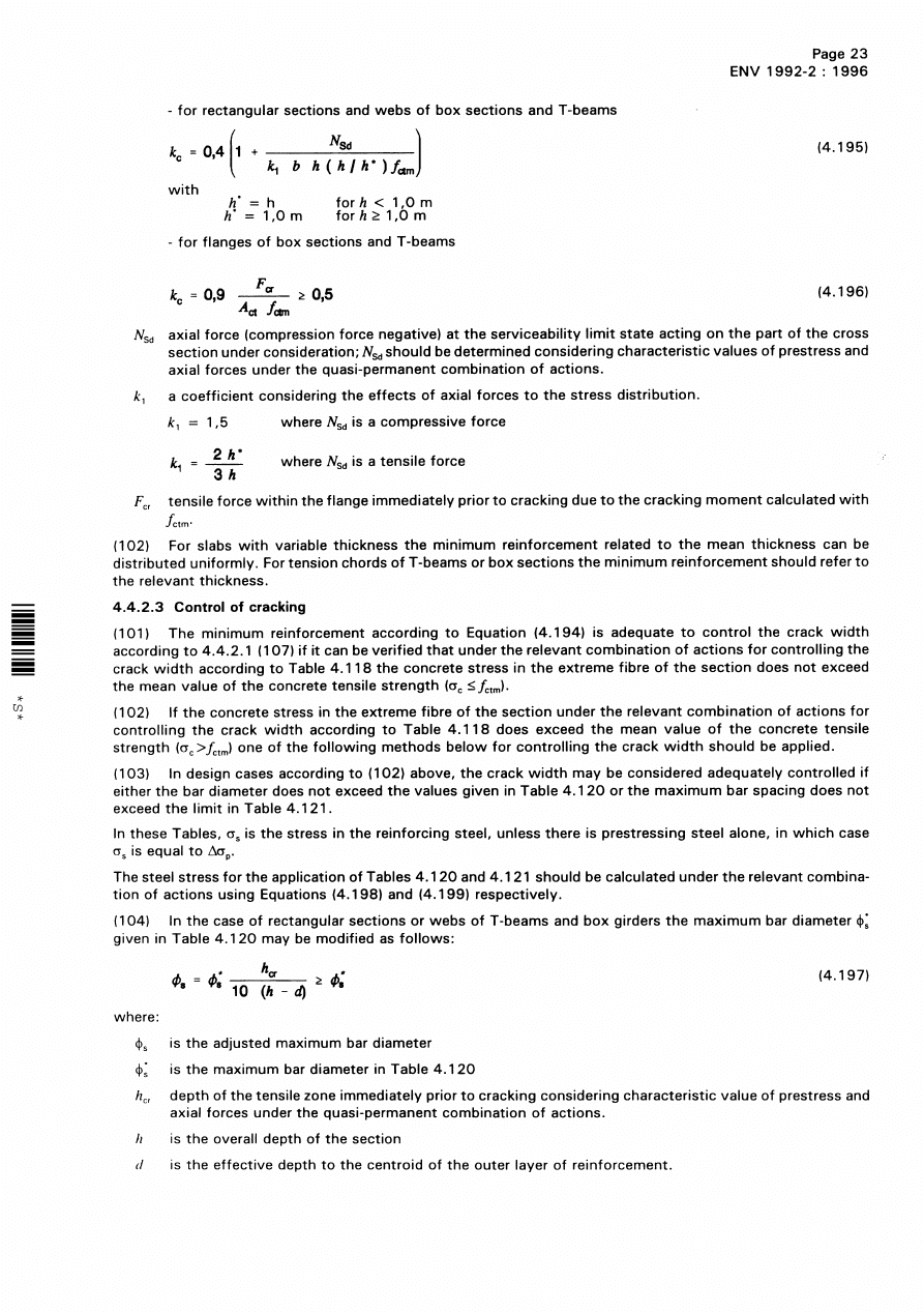
dd) Clause 4.4.2.3 (106)
Replace the definition of Ö¾
s
with the following:
“Ö¾
s
is steel stress in the reinforcing steel or change of stress in prestresing steel relative to the stress
state at decompression, calculated in the cracked state assuming full bond under the relevant
combination of actions.”
A
ct
is the area of the tensile zone immediately prior to cracking of the cross section
web or flange as appropriate taking the tensile strength of concrete as f
ctm
;
Ö
s
is the steel stress in the minimum reinforcement area according to Table 4.120, Ö
s
may be increased by a factor ½ = (f
ctm
/f*
ctm
)
1/2
;
where
f*
ctm
= 2.5 N/mm
2
;
and
f
ctm
is the assumed mean tensile strength of concrete, Ö
s
should not exceed kf
yk
;
and
k
is a coefficient which takes account of the effect of secondary crack formation which
leads to a reduction of restraint forces;
k
= 1.0 for webs or rectangular sections with h k0.3 m or flanges with widths less than
0.3 m; and
= 0.65 for webs or rectangular sections with h U0.8 m or flanges with widths greater
than 0.8 m, intermediate values may be interpolated;
N
sd
is the axial force (compression force negative) at the serviceability limit state acting
on the part of the cross section under consideration. N
sd
should be determined
considering characteristic values of prestress and axial forces under quasi-permanent
combinations of actions or the minimum axial force that can co-exist with the bending
moment considered.
In the definition of k
c
add the following at the end:
If k
c
k 0, no reinforcing steel is required.
Licensed copy:Heriot Watt University, 20/04/2004, Uncontrolled Copy, © BSI

DD ENV 1992-2:2001
xx
© BSI 04-2001
Add the following at end of definitions of Ì
s
and Ì
p
:
“However if there are a variety of sizes, Ì shall be taken as the weighted average size (4As/C;Ì, that
is 4 times total steel area over total steel perimeter).”
ee) Clause 4.4.2.3, Table 4.120
Add at the end of note at bottom “and the bar diameter shall be taken as the equivalent diameter of the
tendon Ì
p
”.
ff) Clause 4.4.2.3, Tables 4.120
Add “or %Öp” after Ö
s"
in heading to the left-hand column.
gg) Clause 4.4.2.3
Replace the existing Table 4.121 with the following:
Table 4.121 — Maximum bar spacing for high bond bars
6.4 Chapter 5. Detailing provisions
a) Table 5.1
Table 5.1 should be replaced by Table 7 of this NAD, which gives minimum diameters of mandrels.
Table 7 — Minimum diameters of mandrels
b) Clause 5.2.6.3
This clause does not apply to 40 mm diameter bars.
c) Clause 5.4.3.2.3
The additional recommendation in the NAD to EC2-1 is not appropriate when a full analysis (e.g. grillage
or finite element) of a slab has been performed.
Maximum bar spacing
(mm)
Steel stress (bending)
Pure flexure
(reinforced sections)
Pure tension
(reinforced sections)
Pre-stressed sections
Ö
s
or %Öpp
N/mm
2
80
—
300
300
120
—
250
250
160
300
200
200
200
250
150
150
240
200
125
100
280
150
75
50
320
100
—
—
360
50
—
—
Hooks, bends, loops
(see Figure 5.2 of ENV 1992-1-1)
Bent-up bars or other curved bars
Bar diameter
Value of minimum concrete cover,
perpendicular to plane of curvature
Ì<20 mm
ÌU20 mm
>100 mm
and >7Ì
>50 mm
and >3Ì
k50 mm
and k3Ì
Minimum diameter of mandrels
for plain bars S 250
4Ì
4Ì
7Ì
8.5Ì
11.4Ì
Minimum diameter of mandrels
for high bond bars S 460
6Ì
8Ì
13Ì
15.7Ì
20.9Ì
Licensed copy:Heriot Watt University, 20/04/2004, Uncontrolled Copy, © BSI

DD ENV 1992-2:2001
© BSI 04-2001
xxi
d) Clause 5.4.3.3 (4)
The ENV 1992-1-1:1991 NAD Additional Requirement 6.5f) does not apply.
e) Clause 5.4.8.1 (3)
Replace Equation [5.22] with:
F
Rdu
= A
co
µ f
cd
k3.3 µc f
cd
A
co
where
µ is as defined in ENV 1992-1-1:1991, 4.2.1.3.3 (11).
f) Clause 5.4.9.3.3 (102)
In the case of continuous or integral bridges consisting of precast pretensioned beams designed for
verification criteria B (see 4.4.0.3) with their ends embedded in in situ concrete at the supports, creep
and shrinkage calculations are not required other than for estimating prestress losses provided the
following apply:
1) either:
i) the angle of skew is not greater than 20°; or
ii) the angle of skew is less than 40° and the aspect ratio is not less than 1 where the aspect ratio is
defined as the ratio of skew span to breadth normal to the skew span;
2) the area of longitudinal bottom steel per beam at the supports is not less than the minimum given by
Equation (4.194) with f
ctm
equal to the tensile strength of the interface between precast and in situ
concrete which may be assumed to be 50 % of the tensile strength of the in situ concrete;
3) the area of steel distributed in b) is also not less than:
i) 3 000/s mm
2
for interior supports in bridges with three or more spans;
ii) 4 000/s mm
2
for the central support of a two span bridge;
iii) 1 500/s mm
2
at end supports in integral bridges;
where s is the beam spacing in metres but not less than 1;
4) where the live load analysis is done using uncracked section properties throughout, including for the
reinforced in situ concrete support section, allowance is made in the serviceability analysis of the beams
in sagging for the effect of a 10 % reduction in the support moment due to redistribution.
6.5 Chapter 6. Construction and workmanship
a) Clause 6.2
Tolerances in this clause should be read as dimensional deviations and should be based on those given
in the Manual of Contract Documents for Highway Works — Volume 1: Specification for Highway Works,
clauses 1710, 1714, 1715 and 1723.
b) Clause 6.3.3.3
Additional guidance is given in the Manual of Contract Documents for Highway Works —
Volume 1: Specification for Highway Works, clause 1717.
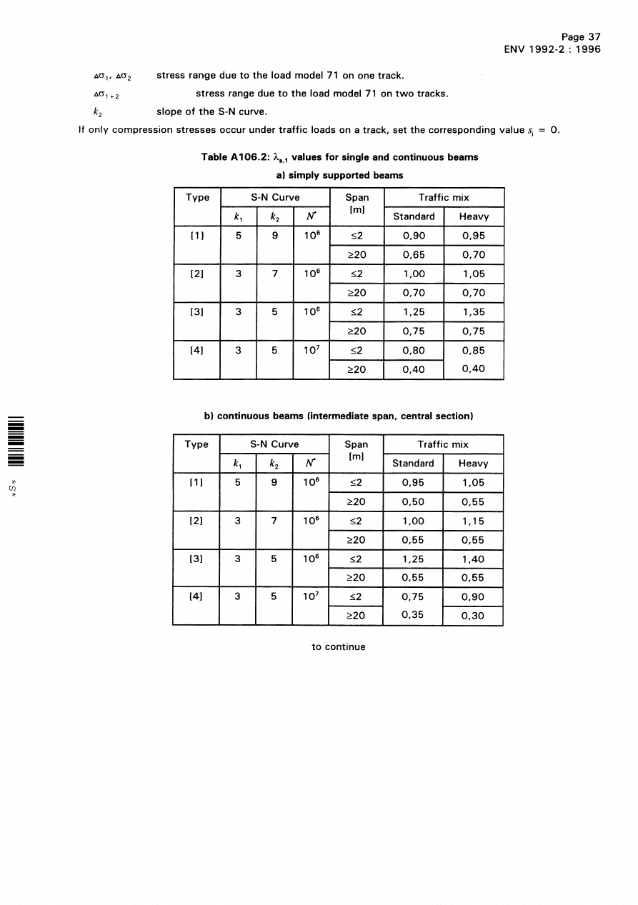
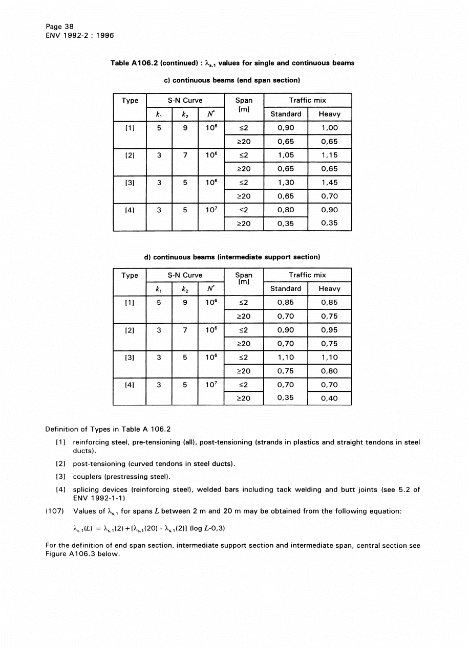
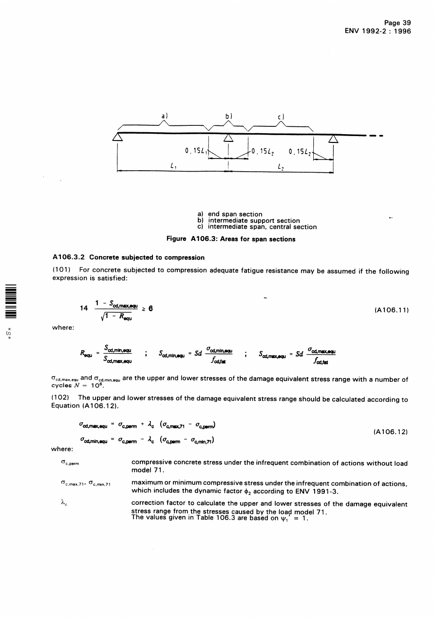
6.6 Appendix 106. Damage equivalent stresses for fatigue verification
a) Clause A106.3.1 (103)
The use of the values of Æ
s,1
given in Table A106.2 should be agreed with the relevant authority.
b) Clause A106.3.2 P(101)
In the definitions of S
cd,min.equ
and S
cd,max,equ
, replace Sd with ¾
Sd
.
A
c1
A
co
¤
(
)
Licensed copy:Heriot Watt University, 20/04/2004, Uncontrolled Copy, © BSI

DD ENV 1992-2:2001
xxii
© BSI 04-2001
Bibliography
Standards publications
BS 1377 (all parts), Methods of test for soils for civil engineering purposes.
BS 4447:1973 (confirmed December 1990), Specification for the performance of prestressing anchorages for
post-tensioned construction.
BS 4449:1997, Specification for carbon steel bars for the reinforcement of concrete.
BS 4466:1989, Specification for scheduling, dimensioning, bending and cutting of steel reinforcement for
concrete.
BS 4482:1985, Specification for cold reduced steel wire for the reinforcement of concrete.
BS 4483:1998, Steel fabric for the reinforcement of concrete.
BS 4486:1980, Specification for hot rolled and processed high tensile alloy steel bars for the prestressing of
concrete.
BS 5400-1:1988, Steel, concrete and composite bridges — General statement.
BS 5400-2:1978, Steel, concrete and composite bridges — Specification for loads.
[This has been partially replaced by BS 5400-9.1:1983 and BS 5400-9.2:1983.]
BS 5400-7:1978, Specification for materials and workmanship, concrete, reinforcement and prestressing
tendons.
BS 5400-9.1:1983, Steel, concrete and composite bridges — Part 9: Bridge bearings —
Section 1: Code of practice for design of bridge bearings.
BS 5400-9.2:1983, Steel, concrete and composite bridges — Part 9: Bridge bearings —
Section 2: Specification for materials, manufacture and installation of bridge bearings.
BS 5400-10:1980, Steel, concrete and composite bridges — Part 10: Code of practice for fatigue.
BS 5896:1980, Specification for high tensile steel wire strand for the prestressing of concrete.
BS 5930:1999, Code of practice for site investigations.
BS 7123:1989, Specification for metal arc welding of steel for concrete reinforcement.
BS 8004:1986, Code of practice for foundations.
EN 447:1996, Grout for prestressing tendons — Specification for common grout.
prEN 10138 (all parts), Prestressing steel.
ENV 206:1990, Concrete — Performance, production, placing and compliance criteria.
ENV 1991 (all parts), Eurocode 1: Basis of design and actions on structures.
ENV 1991-1, Eurocode 1: Basis of design and actions on structures — Part 1: Basis of design.
ENV 1991-2-1:1995, Eurocode 1: Basis of design and actions on structures — Part 2-1: Actions on
structures — Densities, self-weight and imposed loads.
ENV 1991-2-4: 1995, Eurocode 1: Basis of design and actions on structures — Part 2-4: Actions on
structures — Wind actions.
ENV 1991-2-5:1997, Eurocode 1: Basis of design and actions on structures — Part 2-5: Actions on
structures — Thermal actions.
ENV 1992-1-2:1995, Eurocode 2: Design of concrete structures — Part 1-2: General rules — Structural fire
design.
ENV 1992-3:1998, Eurocode 2: Design of concrete structures — Part 3: Concrete foundations.
Licensed copy:Heriot Watt University, 20/04/2004, Uncontrolled Copy, © BSI

DD ENV 1992-2:2001
© BSI 04-2001
xxiii
ENV 1997-1:1994, Eurocode 7: Geotechnical design — Part 1: General rules.
ENV 1998 (all parts), Eurocode 8: Design provisions for earthquake resistance of structures.
ENV 1998-2:1994 , Design provisions for earthquake resistance of structures — Part 2: Bridges.
ENV 10080, Steel for the reinforcement of concrete — Weldable ribbed reinforcing steel B 500 —
Technical delivery conditions for bars, coils and welded fabric.
ISO 161-1:1996, Thermoplastics pipes for the transport of fluids — Nominal outside diameters and nominal
pressures — Part 1: Metric series.
ISO 3607:1977, Polyethylene (PE) pipes — Tolerances on outside diameter and wall thicknesses.
[This has been replaced by ISO 11922-1 and ISO 11922-2].
ISO 11922-1:1997, Thermoplastics pipes for the conveyance of fluids — Dimensions and tolerances —
Part 1: Metric series.
ISO 11922-2:1997, Thermoplastics pipes for the conveyance of fluids — Dimensions and tolerances —
Part 2: Inch-based series.
ISO/DP 9690, Classification of environmental conditions for concrete structures.
Other documents
[1] GREAT BRITAIN. HIGHWAYS AGENCY. Design manual for roads and bridges —
Vol. 1: Highway structures: approval procedures and general design — Section 3: General design —
Part 2: General principles for the design and construction of bridges: use of BS 5400-1:1988.
Publication no. BD 15/92. London: The Stationery Office.
[2] GREAT BRITAIN. HIGHWAYS AGENCY. Design manual for roads and bridges — Vol. 1: Highway
structures: approval procedures and general design — Section 3: General design — Part 1: The design of
concrete highway bridges and structures: use of BS 5400-4:1990. Publication no. BD 24/92. London: The
Stationery Office.
[3] GREAT BRITAIN. HIGHWAYS AGENCY. Design manual for roads and bridges — Vol. 2: Highway
structures: design (substructures and special structures), materials —Section 1: Substructures —
Piled foundations. Publication no. BD 32/88. London: The Stationery Office.
[4] GREAT BRITAIN. HIGHWAYS AGENCY. Design manual for roads and bridges — Vol. 2: Highway
structures: design (substructures and special structures), materials — Section 1: Substructures — Backfilled
retaining walls and bridge abutments. Publication no. BD 30/87. London: The Stationery Office.
[5] GREAT BRITAIN. HIGHWAYS AGENCY. Design manual for roads and bridges — Vol.1: Highway
structures approval procedures and general design — Section 3: General design — Part 4: Tack welding of
reinforcing bars. Publication no. BA 40/93. London: The Stationery Office.
[6] GREAT BRITAIN. HIGHWAYS AGENCY. Design manual for roads and bridges —
Vol. 1 Highway structures: approval procedures and general design — Section 3: General design —
The use of BS 5400-10:1980 — Code of practice for fatigue and amendment no. 1. Publication no. BD 9/81.
London: The Stationery Office.
[7] CONCRETE SOCIETY. Durable bonded post-tensioned concrete bridges. Technical Report No. 47.
Crowthorne: Concrete Society. 1996.
[8] GREAT BRITAIN. HIGHWAYS AGENCY. Design manual for roads and bridges —
Vol. 1: Highway structures — Approval procedures and general design — Section 1: Approval procedures
and general design — Technical approval of highway structures on motorways and other trunk roads —
Part 1: General procedure. Publication no. BD 2/89. London: The Stationery Office.
Licensed copy:Heriot Watt University, 20/04/2004, Uncontrolled Copy, © BSI

xxiv
blank
Licensed copy:Heriot Watt University, 20/04/2004, Uncontrolled Copy, © BSI
Licensed copy:Heriot Watt University, 20/04/2004, Uncontrolled Copy, © BSI
Licensed copy:Heriot Watt University, 20/04/2004, Uncontrolled Copy, © BSI
Licensed copy:Heriot Watt University, 20/04/2004, Uncontrolled Copy, © BSI

Licensed copy:Heriot Watt University, 20/04/2004, Uncontrolled Copy, © BSI
Licensed copy:Heriot Watt University, 20/04/2004, Uncontrolled Copy, © BSI
Licensed copy:Heriot Watt University, 20/04/2004, Uncontrolled Copy, © BSI
Licensed copy:Heriot Watt University, 20/04/2004, Uncontrolled Copy, © BSI
Licensed copy:Heriot Watt University, 20/04/2004, Uncontrolled Copy, © BSI
Licensed copy:Heriot Watt University, 20/04/2004, Uncontrolled Copy, © BSI
Licensed copy:Heriot Watt University, 20/04/2004, Uncontrolled Copy, © BSI
Licensed copy:Heriot Watt University, 20/04/2004, Uncontrolled Copy, © BSI
Licensed copy:Heriot Watt University, 20/04/2004, Uncontrolled Copy, © BSI
Licensed copy:Heriot Watt University, 20/04/2004, Uncontrolled Copy, © BSI
Licensed copy:Heriot Watt University, 20/04/2004, Uncontrolled Copy, © BSI
Licensed copy:Heriot Watt University, 20/04/2004, Uncontrolled Copy, © BSI
Licensed copy:Heriot Watt University, 20/04/2004, Uncontrolled Copy, © BSI
Licensed copy:Heriot Watt University, 20/04/2004, Uncontrolled Copy, © BSI
Licensed copy:Heriot Watt University, 20/04/2004, Uncontrolled Copy, © BSI
Licensed copy:Heriot Watt University, 20/04/2004, Uncontrolled Copy, © BSI
Licensed copy:Heriot Watt University, 20/04/2004, Uncontrolled Copy, © BSI
Licensed copy:Heriot Watt University, 20/04/2004, Uncontrolled Copy, © BSI
Licensed copy:Heriot Watt University, 20/04/2004, Uncontrolled Copy, © BSI
Licensed copy:Heriot Watt University, 20/04/2004, Uncontrolled Copy, © BSI
Licensed copy:Heriot Watt University, 20/04/2004, Uncontrolled Copy, © BSI
Licensed copy:Heriot Watt University, 20/04/2004, Uncontrolled Copy, © BSI
Licensed copy:Heriot Watt University, 20/04/2004, Uncontrolled Copy, © BSI
Licensed copy:Heriot Watt University, 20/04/2004, Uncontrolled Copy, © BSI
Licensed copy:Heriot Watt University, 20/04/2004, Uncontrolled Copy, © BSI
Licensed copy:Heriot Watt University, 20/04/2004, Uncontrolled Copy, © BSI

Licensed copy:Heriot Watt University, 20/04/2004, Uncontrolled Copy, © BSI
Licensed copy:Heriot Watt University, 20/04/2004, Uncontrolled Copy, © BSI
Licensed copy:Heriot Watt University, 20/04/2004, Uncontrolled Copy, © BSI
Licensed copy:Heriot Watt University, 20/04/2004, Uncontrolled Copy, © BSI
Licensed copy:Heriot Watt University, 20/04/2004, Uncontrolled Copy, © BSI
Licensed copy:Heriot Watt University, 20/04/2004, Uncontrolled Copy, © BSI
Licensed copy:Heriot Watt University, 20/04/2004, Uncontrolled Copy, © BSI
Licensed copy:Heriot Watt University, 20/04/2004, Uncontrolled Copy, © BSI
Licensed copy:Heriot Watt University, 20/04/2004, Uncontrolled Copy, © BSI
Licensed copy:Heriot Watt University, 20/04/2004, Uncontrolled Copy, © BSI
Licensed copy:Heriot Watt University, 20/04/2004, Uncontrolled Copy, © BSI
Licensed copy:Heriot Watt University, 20/04/2004, Uncontrolled Copy, © BSI
Licensed copy:Heriot Watt University, 20/04/2004, Uncontrolled Copy, © BSI
Licensed copy:Heriot Watt University, 20/04/2004, Uncontrolled Copy, © BSI
Licensed copy:Heriot Watt University, 20/04/2004, Uncontrolled Copy, © BSI
Licensed copy:Heriot Watt University, 20/04/2004, Uncontrolled Copy, © BSI

DD ENV
1992-2:2001
BSI
389 Chiswick High Road
London
W4 4AL
BSI — British Standards Institution
BSI is the independent national body responsible for preparing
British Standards. It presents the UK view on standards in Europe and at the
international level. It is incorporated by Royal Charter.
Revisions
British Standards are updated by amendment or revision. Users of
British Standards should make sure that they possess the latest amendments or
editions.
It is the constant aim of BSI to improve the quality of our products and services.
We would be grateful if anyone finding an inaccuracy or ambiguity while using
this British Standard would inform the Secretary of the technical committee
responsible, the identity of which can be found on the inside front cover.
Tel: 020 8996 9000. Fax: 020 8996 7400.
BSI offers members an individual updating service called PLUS which ensures
that subscribers automatically receive the latest editions of standards.
Buying standards
Orders for all BSI, international and foreign standards publications should be
addressed to Customer Services. Tel: 020 8996 9001. Fax: 020 8996 7001.
Standards are also available from the BSI website at http://www.bsi-global.com.
In response to orders for international standards, it is BSI policy to supply the
BSI implementation of those that have been published as British Standards,
unless otherwise requested.
Information on standards
BSI provides a wide range of information on national, European and
international standards through its Library and its Technical Help to Exporters
Service. Various BSI electronic information services are also available which give
details on all its products and services. Contact the Information Centre.
Tel: 020 8996 7111. Fax: 020 8996 7048.
Subscribing members of BSI are kept up to date with standards developments
and receive substantial discounts on the purchase price of standards. For details
of these and other benefits contact Membership Administration.
Tel: 020 8996 7002. Fax: 020 8996 7001. Further information about BSI is
available on the BSI website at http://www.bsi-global.com.
Copyright
Copyright subsists in all BSI publications. BSI also holds the copyright, in the
UK, of the publications of the international standardization bodies. Except as
permitted under the Copyright, Designs and Patents Act 1988 no extract may be
reproduced, stored in a retrieval system or transmitted in any form or by any
means – electronic, photocopying, recording or otherwise – without prior written
permission from BSI.
This does not preclude the free use, in the course of implementing the standard,
of necessary details such as symbols, and size, type or grade designations. If these
details are to be used for any other purpose than implementation then the prior
written permission of BSI must be obtained.
If permission is granted, the terms may include royalty payments or a licensing
agreement. Details and advice can be obtained from the Copyright Manager.
Tel: 020 8996 7070.
Licensed copy:Heriot Watt University, 20/04/2004, Uncontrolled Copy, © BSI
Document Outline
Wyszukiwarka
Podobne podstrony:
Eurocode 2 Design of concrete structures Part 1 3
Eurocode 2 Design of concrete structures Part 2
Eurocode 2Design of concrete structures Part 1 1
Eurocode 2 Design of concrete structures part1 2
Eurocode 2 Design of concrete structures part4
Eurocode 2 Design of concrete structures part4
Eurocode 2 Part 3 2006 UK NA Design of concrete structures Liquid retaining and containing struc
Eurocode 2 Part 1 1 2004 NA UK Design of concrete structures General rules and rules for buildin
Eurocode 2 Part 3 2006 Design of concrete structures Liquid retaining and containing structures
Eurocode 2 Part 2 2004 UK NA Design of concrete structures Concrete bridges Design and detailin
Eurocode 5 EN 1995 1 1 Design Of Timber Structures Part 1 1 General Rules
Eurocode 5 EN 1995 1 1 Design Of Timber Structures Part 1 1 General Rules
Eurocode 6 Part 1 2 1996 2005 Design of Masonry Structures General Rules Structural Fire Design
Eurocode 6 Part 2 1996 2006 Design of Masonry Structures Design Considerations, Selection of Mat
Eurocode 3 Part 1 7 2009 Design of Steel Structures Plated Structures Subject to Out of Plane Loa
więcej podobnych podstron