CAPACITIES AND
SPECIFICATIONS
S6.00-7.00XL (S135-155XL, S155XLS,
S135-155XL
2
) [B024, C024]
PART NO. 897395
8000 SRM 454

SAFETY PRECAUTIONS
MAINTENANCE AND REPAIR
• When lifting parts or assemblies, make sure all slings, chains, or cables are correctly
fastened, and that the load being lifted is balanced. Make sure the crane, cables, and
chains have the capacity to support the weight of the load.
• Do not lift heavy parts by hand, use a lifting mechanism.
• Wear safety glasses.
• DISCONNECT THE BATTERY CONNECTOR before doing any maintenance or repair
on electric lift trucks.
• Disconnect the battery ground cable on internal combustion lift trucks.
• Always use correct blocks to prevent the unit from rolling or falling. See HOW TO PUT
THE LIFT TRUCK ON BLOCKS in the Operating Manual or the Periodic Mainte-
nance section.
• Keep the unit clean and the working area clean and orderly.
• Use the correct tools for the job.
• Keep the tools clean and in good condition.
• Always use HYSTER APPROVED parts when making repairs. Replacement parts
must meet or exceed the specifications of the original equipment manufacturer.
• Make sure all nuts, bolts, snap rings, and other fastening devices are removed before
using force to remove parts.
• Always fasten a DO NOT OPERATE tag to the controls of the unit when making repairs,
or if the unit needs repairs.
• Be sure to follow the WARNING and CAUTION notes in the instructions.
• Gasoline, Liquid Petroleum Gas (LPG), Compressed Natural Gas (CNG), and Diesel fuel
are flammable. Be sure to follow the necessary safety precautions when handling these
fuels and when working on these fuel systems.
• Batteries generate flammable gas when they are being charged. Keep fire and sparks
away from the area. Make sure the area is well ventilated.
NOTE:
The following symbols and words indicate safety information in this
manual:
WARNING
Indicates a condition that can cause immediate death or injury!
CAUTION
Indicates a condition that can cause property damage!

Capacities and Specifications
Table of Contents
TABLE OF CONTENTS
Lift Truck Weights .............................................................................................................................................
Hydraulic System...............................................................................................................................................
Tire Sizes ............................................................................................................................................................
Electrical System ...............................................................................................................................................
Engine Specifications.........................................................................................................................................
Transmission Oil Pressures...............................................................................................................................
Upright Speeds...................................................................................................................................................
Torque Specifications .........................................................................................................................................
Frame .............................................................................................................................................................
Engine - GM V-6 ............................................................................................................................................
Engine - Perkins ............................................................................................................................................
Powershift Transmission...............................................................................................................................
Manual Transmission ....................................................................................................................................
Oil Clutch Assembly ......................................................................................................................................
Steering System.............................................................................................................................................
Brake System.................................................................................................................................................
Hydraulic System ..........................................................................................................................................
Main Control Valve........................................................................................................................................
Tilt Cylinders .................................................................................................................................................
Upright ...........................................................................................................................................................
Drive Axle ......................................................................................................................................................
This section is for the following models:
S6.00-7.00XL (S135-155XL, S155XLS, S135-155XL
2
) [B024, C024]
©2003 HYSTER COMPANY
i

"THE
QUALITY
KEEPERS"
HYSTER
APPROVED
PARTS

8000 SRM 454
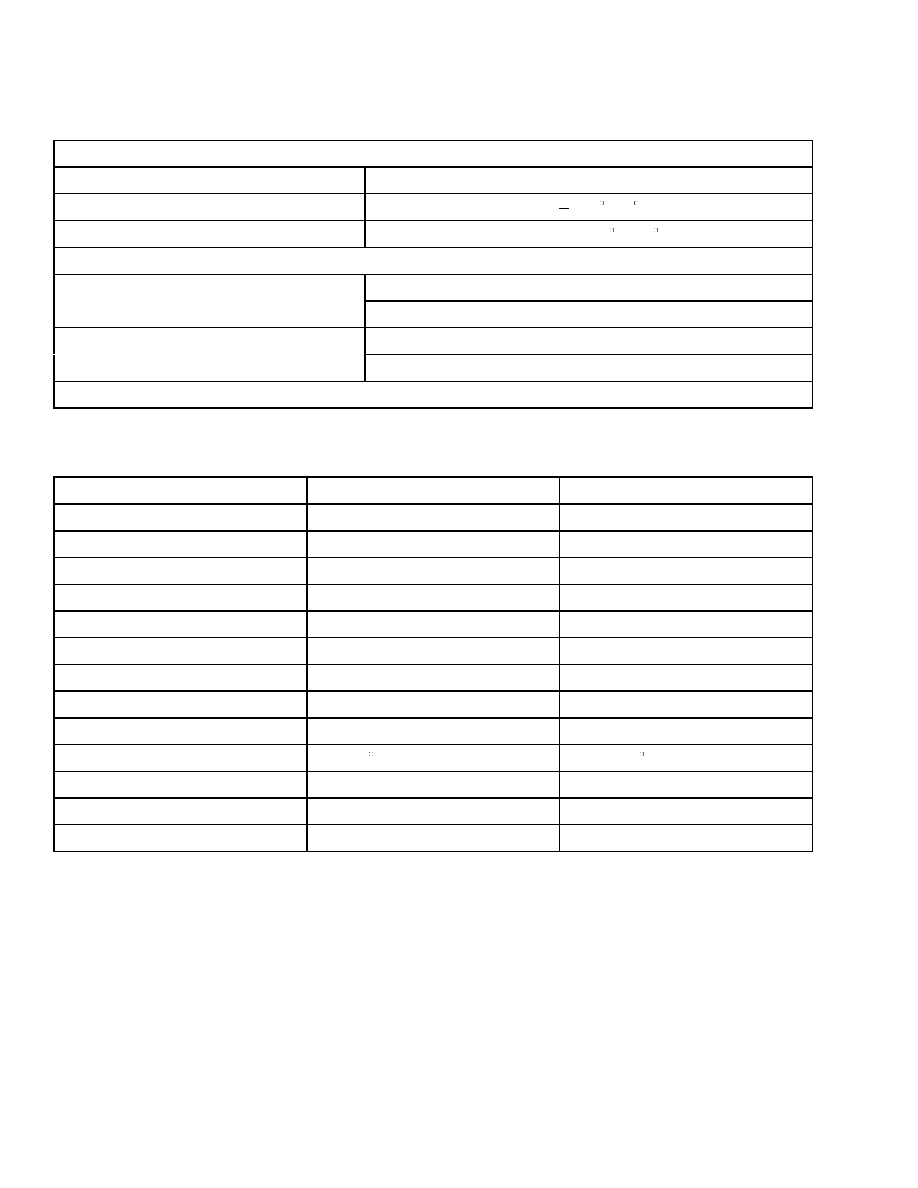
Tire Sizes
Lift Truck Weights
Unit
kg
lb
S6.00XL (S135XL, S135XL
2
)
8860
19,533
S7.00XL (S155XL, 155XLS, S155XL
2
)
9590
21,142
NOTE:
Lift trucks equipped with overhead guard, 4570 mm (180 in.) B.O.F. Vista 2-stage upright, 1220 mm
(48 in.) carriage, load backrest extension, 1220 mm (48 in.) forks, gas engine, and 90 kg (200 lb) operator.
Hydraulic System
Item
Specification
Hydraulic System Capacity
50.2 liter (13.3 gal)
Hydraulic Tank Capacity
39.5 liter (10.4 gal) Drain and Refill
Relief Pressures*
Main Control Valve
Lift Circuit
20.88 to 21.20 MPa (3025 to 3075 psi)
Tilt and Auxiliary Circuit
15.34 to 15.68 MPa (2225 to 2275 psi)
Steering Circuit
12.075 MPa (1750 psi)
Brake Booster
2.275 MPa (330 psi)
Hydraulic Pump Capacity
102 liter/min (27.0 gal/min) at 21.0 MPa (3050 psi)
Steering Pump Capacity
19.7 liter/min (5.2 gal/min) at 12.075 MPa (1750 psi)
*Oil temperature 49 C (120 F) and engine speed at 2500 rpm.
Tire Sizes
Model
Steering
Drive
S6.00XL (S135XL, S135XL
2
)
22 × 8 × 16
28 × 12 × 22
S7.00XL (S155XL, S155XLS, S155XL
2
)
22 × 8 × 16
28 × 12 × 22
1
Engine Specifications
8000 SRM 454
Electrical System
Battery
SAE No.
24-335
Cold Cranking
30 sec. min. at
17.8 C (0 F) to 1.2 volts
Reserve Capacity
85 min. at 26 C (80 F)
Alternator Output
38 amps @ 650 rpm (Hot)
GM V-6
62 amps @ 2500 rpm (Hot)
42 amps @ 650 rpm (Hot)
Perkins
62 amps @ 2500 rpm (Hot)
All models - 12-volt negative ground
Engine Specifications
Item
GM V-6 4.3
Perkins 1004-4
Number of Cylinders
6
4
Firing Order
1-6-5-4-3-2
1-3-4-2
Bore
101.6 mm (3.99 in.)
100.00 mm (3.937 in.)
Stroke
88.39 mm (3.48 in.)
127.00 mm (5.00 in.)
Displacement
4.3 liter (262.4 in.
3
)
4.0 liter (244.0 in.
3
)
Compression Ratio
9.3:1
16.5:1
Idle Speed
625 to 675 rpm
725 to 775 rpm
Governor Speed
2400 to 2500 rpm
2400 to 2500 rpm
Stall Speed rpm (Engine at 50 hrs)
1810 (Gas) 1735 (LPG)
2090 rpm
Timing
0 BTDC at 650 rpm
16 BTDC (Static)
Oil Pressure (Minimum)
207 to 308 kPa (30 to 45 psi)
276 kPa (40 psi)
Valve Clearance
Not adjustable
0.20 mm (0.008 in.) Cold
Intake Exhaust
Not adjustable
0.45 mm (0.018 in.) Cold
2
8000 SRM 454
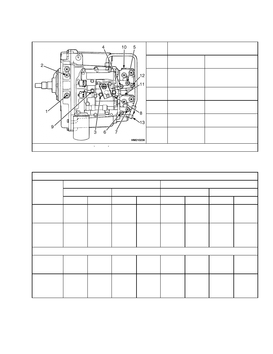
Upright Speeds
Transmission Oil Pressures
Port
No.
Powershift Transmission Pressures*
1
System
Pressure
1179 to 1427 kPa
(171 to 207 psi)
2
Torque
Converter
Pressure
765 to 903 kPa
(111 to 131 psi)
3,4,5,6,7
Clutch
Pressure
855 to 993 kPa
(124 to 144 psi)
8,9
Solenoid
Pressure
827 to 1103 kPa
(120 to 160 psi)
10,11
Lubrication
Pressure
131 to 173 kPa
(19 to 25 psi)
12,13
Lubrication
Pressure
62 to 104 kPa
(9 to 15 psi)
*Oil temperature at least 82 C (180 F) and engine speed at 2000 rpm.
Upright Speeds
Two-Stage Upright
Lifting
Lowering
No Load
Rated Load
No Load
Rated Load
Unit
m/min
ft/min
m/min
ft/min
m/min
ft/min
m/min
ft/min
S6.00XL
(S135XL,
S135XL
2
)
25.6
84
24.1
79
26.8
88
32.9
108
S7.00XL
(S155XL,
S155XLS,
S155XL
2
)
25.6
84
24.1
79
26.8
88
33.6
110
Three-Stage Upright
S6.00XL
(S135XL,
S135XL
2
)
24.4
80
22.3
73
23.5
77
33.6
110
S7.00XL
(S155XL,
S155XLS,
S155XL
2
)
24.4
80
22.3
73
23.5
77
33.8
111
3

Torque Specifications
8000 SRM 454
Torque Specifications
FRAME
Counterweight Capscrew
655 N•m (485 lbf ft)
ENGINE - GM V-6
Intake Manifold Capscrews
47 N•m (35 lbf ft)
Valve Cover Capscrews
10 N•m (7 lbf ft)
Exhaust Manifold Capscrews
35 N•m (25 lbf ft)
Center Port 25 N•m (20 lbf ft)
Outer Ports 47 N•m (35 lbf ft)
Camshaft Sprocket Capscrews
25 N•m (20 lbf ft)
Vibration Damper Capscrew
81 N•m (60 lbf ft)
Main Bearing Cap Capscrews
68 N•m (50 lbf ft)
Connecting Rods
47 N•m (35 lbf ft)
Flywheel Capscrews
81 N•m (60 lbf ft)
Flywheel Housing Capscrews
50 N•m (40 lbf ft)
Engine Mount to Engine Capscrews
35 N•m (25 lbf ft)
Engine Mount to Mount Plate Bolts
68 N•m (50 lbf ft)
Engine Mount to Flywheel Housing Capscrews
165 N•m (120 lbf ft)
Engine Mount Bolts
122 N•m (90 lbf ft)
ENGINE - PERKINS
Engine Mount to Engine Capscrews
68 N•m (50 lbf ft)
Engine Mount Bolts
122 N•m (90 lbf ft)
POWERSHIFT TRANSMISSION
Torque Converter Housing Capscrews
31 N•m (23 lbf ft)
Torque Converter Drive Plate Capscrews
44 N•m (32 lbf ft)
Engine Mount Capscrews at Torque Converter
110 N•m (80 lbf ft)
Universal Joint Capscrews
50 N•m (37 lbf ft)
Transmission Cover Capscrews
38 N•m (28 lbf ft)
Manifold Block Capscrews
38 N•m (28 lbf ft)
Oil Pump Capscrews
38 N•m (28 lbf ft)
Torque Converter Housing-to-Trans-
mission Capscrews
38 N•m (28 lbf ft)
Control Valve Capscrews
19 N•m (14 lbf ft)
MANUAL TRANSMISSION
Pinion Nut
1085 N•m (800 lbf ft)
Ring Gear Capscrews
140 N•m (105 lbf ft)
Differential Case Capscrews
140 N•m (105 lbf ft)
Range Main Shaft Capscrews
122 N•m (90 lbf ft)
Pinion Bearing Carrier Capscrews
90 N•m (66 lbf ft)
Bearing Retainer Capscrews
38 N•m (28 lbf ft)
4

8000 SRM 454
Torque Specifications
Transmission Cover Capscrews
38 N•m (28 lbf ft)
Differential Bearing Cap Capscrews
225 N•m (165 lbf ft)
Transmission Housing Capscrews
90 N•m (66 lbf ft)
OIL CLUTCH ASSEMBLY
Pressure Plate Cover Capscrews
20 N•m (15 lbf ft)
Clutch-to-Flywheel Housing Capscrews
38 N•m (28 lbf ft)
Bearing Carrier Capscrews
38 N•m (28 lbf ft)
Mount Bracket Capscrews
165 N•m (122 lbf ft)
Mount Capscrews
40 N•m (30 lbf ft)
Universal Joint
24 N•m (18 lbf ft)
Brake Pedal Bracket Capscrews
38 N•m (28 lbf ft)
STEERING SYSTEM
Axle Mount Capscrews
250 to 275 N•m (185 to 200 lbf ft)
Bearing Cap for Spindle Capscrews
52 N•m (38 lbf ft)
Tie Rod Nut
160 N•m (118 lbf ft)
Steering Cylinder Capscrews
225 N•m (165 lbf ft)
Wheel Bearing Adjustment Nut
200 N•m (150 lbf ft) Initial
35 N•m (25 lbf ft) Final
BRAKE SYSTEM
Back Plate Nuts
55 to 80 N•m (41 to 59 lbf ft) Initial
110 to 125 N•m (80 to 92 lbf ft) Final
Brake Booster Mount Capscrews
38 N•m (28 lbf ft)
HYDRAULIC SYSTEM
Capscrews for Special Blocks for
Pump Drive Chain
20 N•m (15 lbf ft)
MAIN CONTROL VALVE
Lever Pivot Capscrews
19 N•m (14 lbf ft)
Collar Screw for Two Plunger Levers
7 N•m (5 lbf ft)
TILT CYLINDERS
Piston Nut
300 to 325 N•m (220 to 240 lbf ft)
End Plug
400 to 500 N•m (295 to 370 lbf ft)
Rod End Lock Capscrews
77 N•m (57 lbf ft)
Anchor Pin Retainer Capscrews
77 N•m (57 lbf ft)
UPRIGHT
Two-Stage Lift Cylinder Mount Capscrews
555 N•m (410 lbf ft)
Pivot Pin Capscrews
435 N•m (320 lbf ft)
Tilt Cylinder Rod End Anchor Pin
and Lock Bolt
77 N•m (57 lbf ft)
Sideshift Carriage
Keeper Plate Capscrews 90 N•m (65 lbf ft)
Side Roller Mount Capscrews 90 N•m (65 lbf ft)
Guide Rollers 345 N•m (255 lbf ft)
Side Rollers 90 N•m (65 lbf ft)
DRIVE AXLE
Drive Axle-to-Transmission Housing
Capscrews
65 N•m (50 lbf ft)
5

Torque Specifications
8000 SRM 454
Axle Mount Capscrews
1040 N•m (768 lbf ft)
Axle Shaft Capscrews
165 N•m (122 lbf ft)
Wheel Nuts
610 to 680 N•m (450 to 500 lbf ft)
Wheel Bearing Adjustment Nut
200 N•m (150 lbf ft) Initial
35 N•m (25 lbf ft) Final
Wheel Bearing Lock Nut
135 N•m (100 lbf ft)
Pinion Nut
1085 N•m (800 lbf ft)
6


TECHNICAL PUBLICATIONS
8000 SRM 454
10/03 (9/03)(11/02)(3/89) Printed in United Kingdom
Document Outline
- toc
Wyszukiwarka
Podobne podstrony:
1494145 8000SRM0940 (10 2003) UK EN
1466241 1600SRM0732 (10 2003) UK EN
899784 2200SRM0002 (10 2003) UK EN
1456997 8000SRM0708 (10 2004) UK EN
897121 1900SRM0339 (10 2003) UK EN
1483865 8000SRM0916 (12 2003) UK EN
897113 8000SRM0331 (09 2003) UK EN
1524437 8000SRM1035 (09 2003) UK EN
910076 1600SRM0054 (10 2003) UK EN
więcej podobnych podstron