Micrologic control units
2.0 A, 5.0 A, 6.0 A and 7.0 A
Low Voltage Products
User manual
We do more with electricity.

Micrologic A
Schneider Electric
1
Discovering your control unit
2
Identifying your control unit
2
Overview of functions
4
Setting your control unit
10
Selecting the type of neutral protection
10
Setting procedure
11
Setting the Micrologic 2.0 A control unit
12
Setting the Micrologic 5.0 A control unit
13
Setting the Micrologic 6.0 A control unit
14
Setting the Micrologic 7.0 A control unit
15
Fault and status indications
16
Resetting the fault indications
and checking battery status
16
Testing the earth-fault
and earth-leakage functions
17
Menus
18
Accessing the menus
18
Measuring phase currents
19
Displaying the maximum current values
20
Resetting the maximum current values
21
Viewing the settings
22
Technical appendix
24
Tripping curves
24
Changing the long-time rating plug
26
Zone selective interlocking (ZSI)
27
Digital display
28
Thermal memory
29
Micrologic control units
2.0 A, 5.0 A, 6.0 A and 7.0 A
Micrologic A
Schneider Electric
2
Discovering your
control unit
E51384A
E51450A
All Compact NS800-3200 and Masterpact
NT and NW circuit breakers are equipped
with a Micrologic control unit
that can be changed on site.
Control units are designed to protect
power circuits and connected loads.
Identifying your control unit
Designations
E51352A
X: type of protection
c
2 for basic protection
c
5 for selective protection
c
6 for selective + earth-fault protection
c
7 for selective + earth-leakage protection
Y: version number
identification of the control-unit generation.
"0" signifies the first generation.
Z: type of measurement
c
A for "ammeter"
c
P for "power meter"
c
H for "harmonic meter"
c
no indication: no measurements
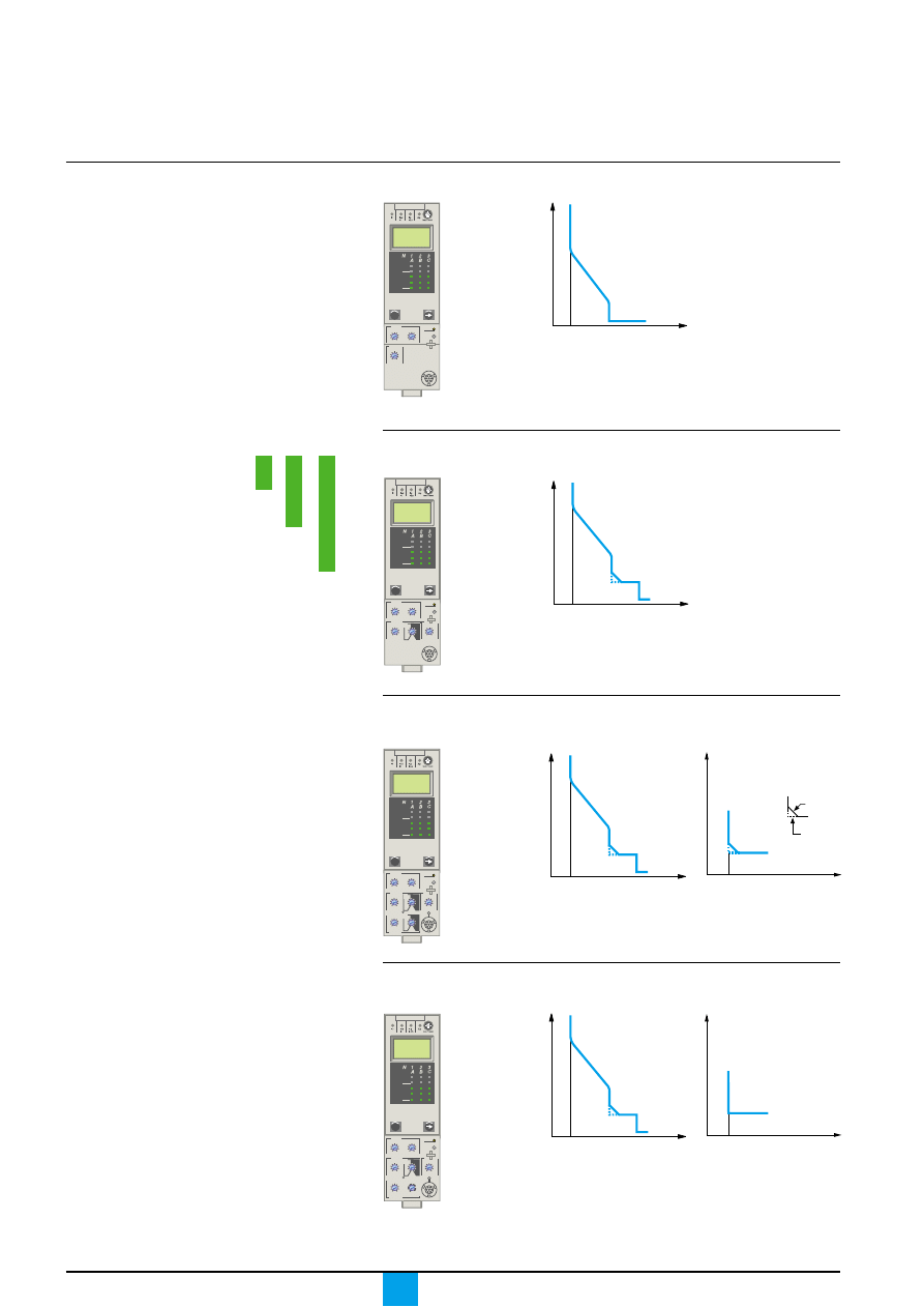
Micrologic 2.0 A: basic protection and ammeter
Long time + Instantaneous
Micrologic 5.0 A: selective protection and ammeter
Long time + Short time + Instantaneous
E51385A
E51354A
0
Ir
Isd
I
t
0
Ir
I
t
Ii
Isd
Micrologic 6.0 A: selective + earth-fault protection and
ammeter
E51387A
E51354A
E51395A
0
Ir
I
t
Ii
Isd
Long time + Short time
+ Instantaneous
Earth-fault protection
Micrologic 7.0 A: selective + earth-leakage protection and
ammeter
E51388A
E51354A
E51452A
0
Ir
I
t
Ii
Isd
Long time + Short time
+ Instantaneous
Earth-leakage protection
Micrologic 2.0 A
Y
X
Z
Micrologic 2.0 A
40
100 %
%
menu
long time
alarm
instantaneous
.4
.5
.6
.7
.8
.9
.95
.98
1
Ir
x In
.5
1
2
4
8
12
16
20
tr
(s)
at 6 Ir
24
x Ir
2
2.5
3 4 5
6
1.5
setting
Isd
8
10
Micrologic 5.0 A
40
100 %
%
menu
delay
short time
tsd
(s)
long time
alarm
tr
(s)
setting
.4
.5
.6
.7
.8
.9
.95
.98
1
Ir
x In
.5
1
2
4
8 12
16
20
at 6 Ir
24
x Ir
2
2.5
3
4 5
6
8
10
Isd
1.5
on
I
2
t
.
2
.
4
.
4
.
1
.
3
.
1
0
I i
x In
3
4
8
off
2
.
3
instantaneous
.
2
6
15
10
12
Micrologic 6.0 A
40
100 %
%
menu
delay
short time
on
I
2
t
.
2
.
3
.
4
.
4
.
1
.
2
.
1
0
long time
alarm
ground fault
setting
4
test
.4
.5
.6
.7
.8
.9
.95
.98
1
Ir
x In
.5
1
2
4
8
12
16
20
tr
(s)
at 6 Ir
24
x Ir
2
2.5
3
4 5
6
8
10
Isd
1.5
tsd
(s)
x In
3
6
8 10
12
15
off
2
B
C
D E F
G
H
I
Ig
A
on
I
2
t
.
2
.
3
.
4
.
4
.
1
.
2
.
3
.
1
0
off
tg
(s)
.
1
.
3
instantaneous
I i
0
I
t
I
2
t off
I
2
t on
Ig
Micrologic 7.0 A
40
100 %
%
menu
.98
delay
short time
off
long time
alarm
setting
earth leakage
test
.4
.5
.6
.7
.8
.9
.95
1
Ir
x In
tr
(s)
.5
1
2
4
8
12
16
20
at 6 Ir
24
x Ir
2
2.5
3
4 5
6
8
10
Isd
1.5
tsd
(s)
on
I
2
t
.
2
.
3
.
4
.
4
.
1
.
2
.
3
.
1
0
x In
3
4
6
8
10
12
15
off
2
1
2
3
5
7
10
20
30
.5
I
∆
n
800
∆
I
60
140
230 350
instantaneous
I i
0
I
t
I
∆
n
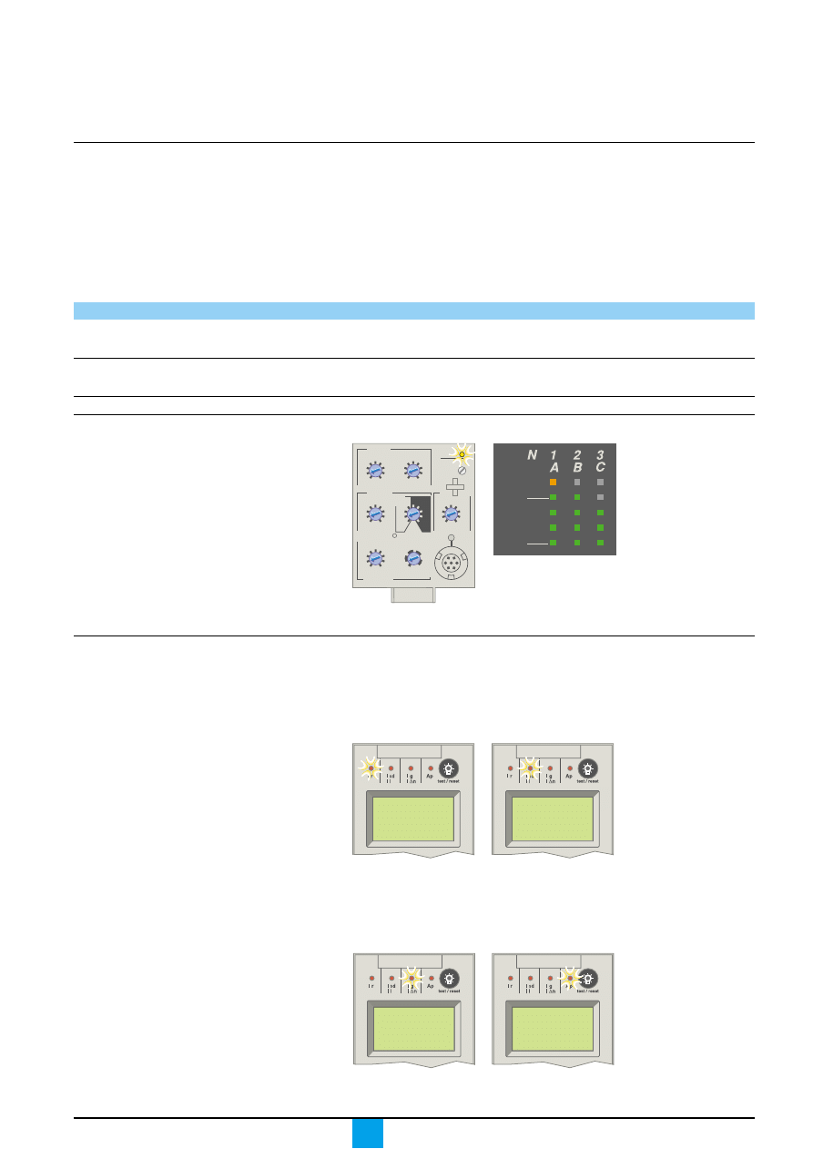
Micrologic A
Schneider Electric
3
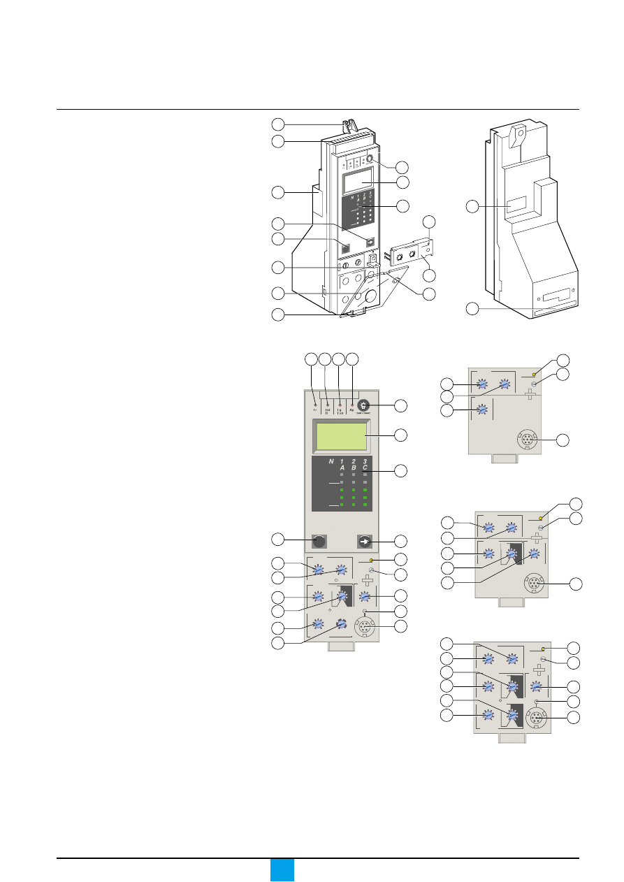
1
top fastener
2
bottom fastener
3
protective cover
4
cover opening point
5
lead-seal fixture for protective cover
6
long-time rating plug
7
screw for long-time rating plug
8
connection with circuit breaker
9
infrared link with communications interfaces
10
terminal block for external connections
11
housing for battery
12
digital display
13
three-phase bargraph and ammeter
Adjustment dials
14
long-time current setting Ir
15
long-time tripping delay tr
16
short-time pickup Isd
17
short-time tripping delay tsd
18
instantaneous pick-up Isd
19
instantaneous pick-up Ii
20
earth-fault pick-up Ig
21
earth-fault tripping delay tg
22
earth-leakage pick-up I
∆
n
23
earth-leakage tripping delay
∆
t
Indications
24
LED indicating long-time tripping
25
LED indicating short-time tripping
26
LED indicating earth-fault
or earth-leakage tripping
27
LED indicating auto-protection tripping
28
LED indicating an overload
Navigation
29
navigation button to change menus
30
navigation button to view menu contents
31
button for fault-trip reset and battery test
Test
32
test button for earth-fault and earth-leakage
protection
33
test connector
Presentation
E51389A
E51390A
E51391A
Micrologic 7.0 A
Micrologic 2.0 A
Micrologic 5.0 A
E51394A
E51393A
Micrologic 6.0 A
E51392A
3
2
1
10
5
.4
.5
.6
.7
.8 .9
.95
.98
1
.5
1
2
4
8 12
16
20
24
long
time
alarm
Ir
tr
(s)
x In
at
6 Ir
7
11
12
Micr
olog
ic 7.0
A
40
100 %
%
men
u
31
13
4
30
29
6
8
9
instantaneous
long time
alarm
.4
.5
.6
.7
.8
.9
.95
.98
1
Ir
x In
.5
1
2
4
8
12
16
20
tr
(s)
at 6 Ir
24
x Ir
2
2.5
3 4 5
6
8
10
1.5
setting
Isd
14
15
18
33
28
7
Micrologic 7.0 A
40
100 %
%
menu
delay
short time
I i
long time
alarm
test
800
earth leakage
1
2
3
5
7
10
20
30
∆
I
(ms)
60
.5
140
230
350
I
∆
n
(A)
setting
x Ir
2
2.5
3
4 5
6
8
10
1.5
x In
3
4
6
8
10
12
15
off
2
.5
1
2
4
8
12
16
20
tr
(s)
at 6 Ir
24
.4
.5
.6
.7
.8
.9
.95
.98
1
Ir
x In
29
15
14
17
16
23
22
30
28
7
19
33
31
12
13
27
26
25
24
tsd
(s)
on
I
2
t
.
2
.
3
.
4
.
4
.
1
.
2
.
3
.
1
0
off
instantaneous
Isd
32
.95
.98
setting
delay
short time
I i
tsd
(s)
long time
alarm
.4
.5
.6
.7
.8
.9
1
Ir
x In
.5
1
2
4
8
12
16
20
tr
(s)
at 6 Ir
24
x Ir
2
2.5
3
4 5
6
8
10
Isd
1.5
on
I
2
t
.
2
.
3
.
4
.
4
.
1
.
2
.
3
.
1
0
x In
3
4
6
8 10
12
15
off
2
14
15
16
17
19
28
7
33
instantaneous
.4
.5
.6
.7
.8
.9
.95
.98
1
delay
short time
I i
tsd
(s)
on
I
2
t
.
2
.
3
.
4
.
4
.
1
.
2
.
3
.
1
0
off
long time
alarm
Ir
x In
ground fault
B
C
D
E
F
G
H
I
Ig
tg
(s)
on
I
2
t
.
2
.
3
.
4
.
4
.
1
.
2
.
3
.
1
0
off
A
.5
1
2
4
8
12
16
20
tr
(s)
at 6 Ir
24
setting
x Ir
2
2.5
3
4
5
6
8
10
Isd
1.5
x In
3
4
6
8
10
12
15
off
test
instantaneous
15
14
17
16
21
20
28
7
19
32
33
2
Micrologic A
Schneider Electric
4
Discovering your
control unit
Protection settings
Depending on the type of installation, it is possible to set the tripping curve of your
control unit using the parameters presented below.
Long-time protection
The long-time protection function protects cables (phases and neutral)
against overloads. This function is based on true rms measurements.
Thermal memory
The thermal memory continuously accounts for the amount of heat in the cables,
both before and after tripping, whatever the value of the current (presence of
an overload or not). The thermal memory optimises the long-time protection
function of the circuit breaker by taking into account the temperature rise in the
cables. The thermal memory assumes a cable cooling time of approximately
15 minutes.
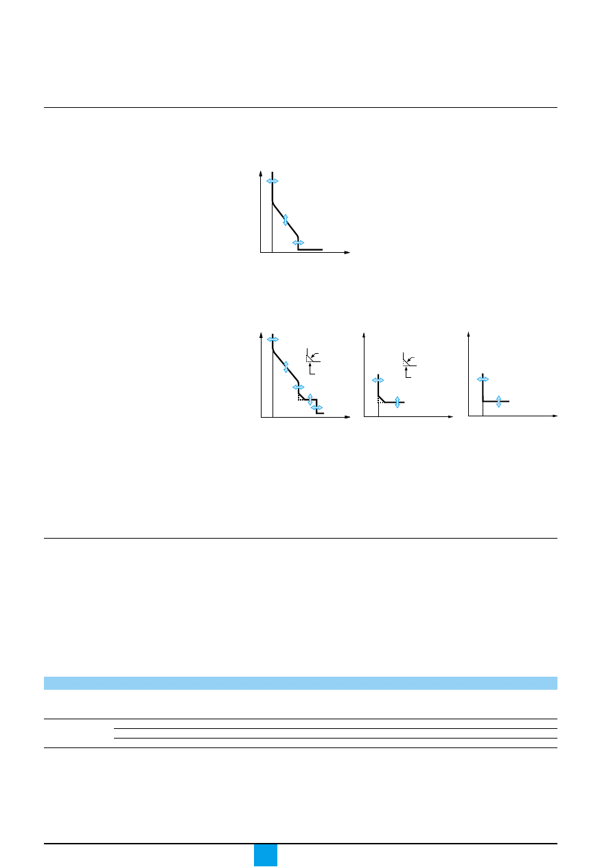
Long-time current setting Ir and standard tripping delay tr
E51358A
Overview of functions
Current protection
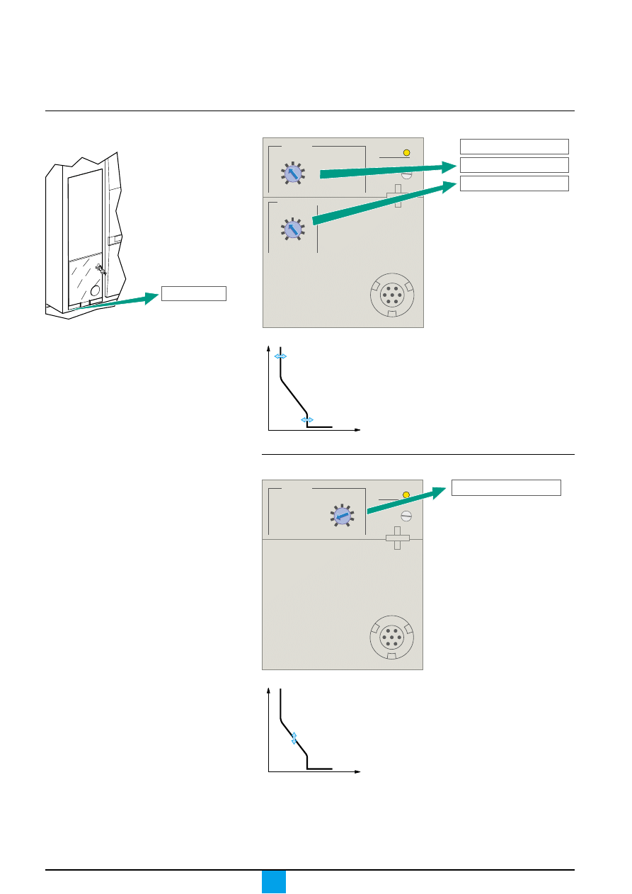
Micrologic 2.0 A
1. current setting Ir (long time)
2. tripping delay tr (long time) for 6 x Ir
3. pick-up Isd (instantaneous)
Micrologic control unit
2.0 A and 5.0 A
current setting
Ir = In x …(*)
0.4
0.5
0.6
0.7
0.8
0.9
0.95
0.98
1
tripping between
other ranges or disable by changing rating plug
1.05 and 1.20 x Ir
time delay (s)
tr at 1.5 x Ir
12.5
25
50
100
200
300
400
500
600
accuracy:
tr at 6 x Ir
0.5
1
2
4
8
12
16
20
24
0 to -20 %
tr at 7.2 x Ir
0.34
0.69
1.38
2.7
5.5
8.3
11
13.8
16.6
* In: circuit breaker rating
Setting accuracy of the Ir setting may be enhanced by using a different long-time
rating plug.
See the technical appendix "Changing the long-time rating plug".
0
Ir
Isd
I
t
1
2
3
E51359A
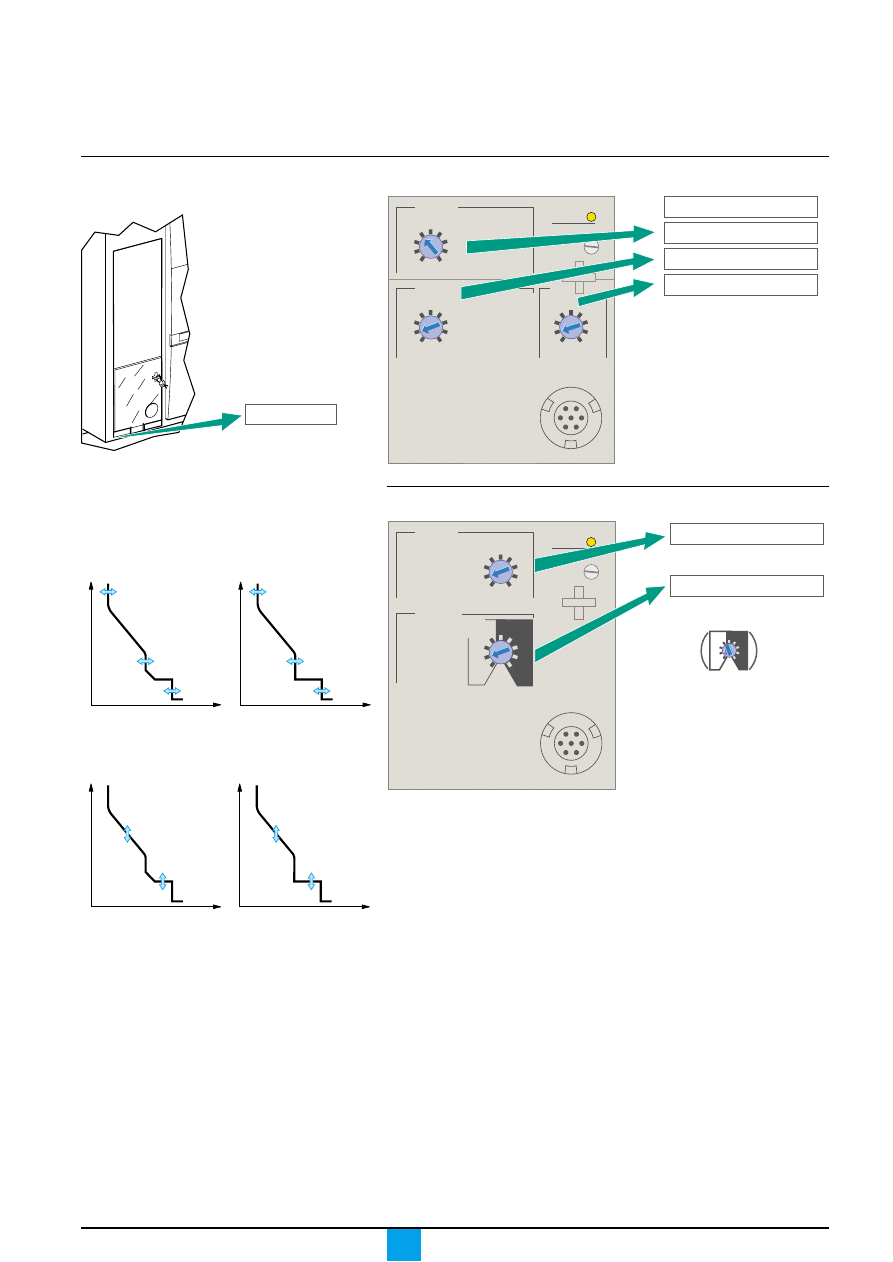
Micrologic 5.0 A, 6.0 A,
7.0 A
1
2
3
4
5
0
Ir
Isd
I
t
Ii
I
2
t off
I
2
t on
E51386A
E51396A
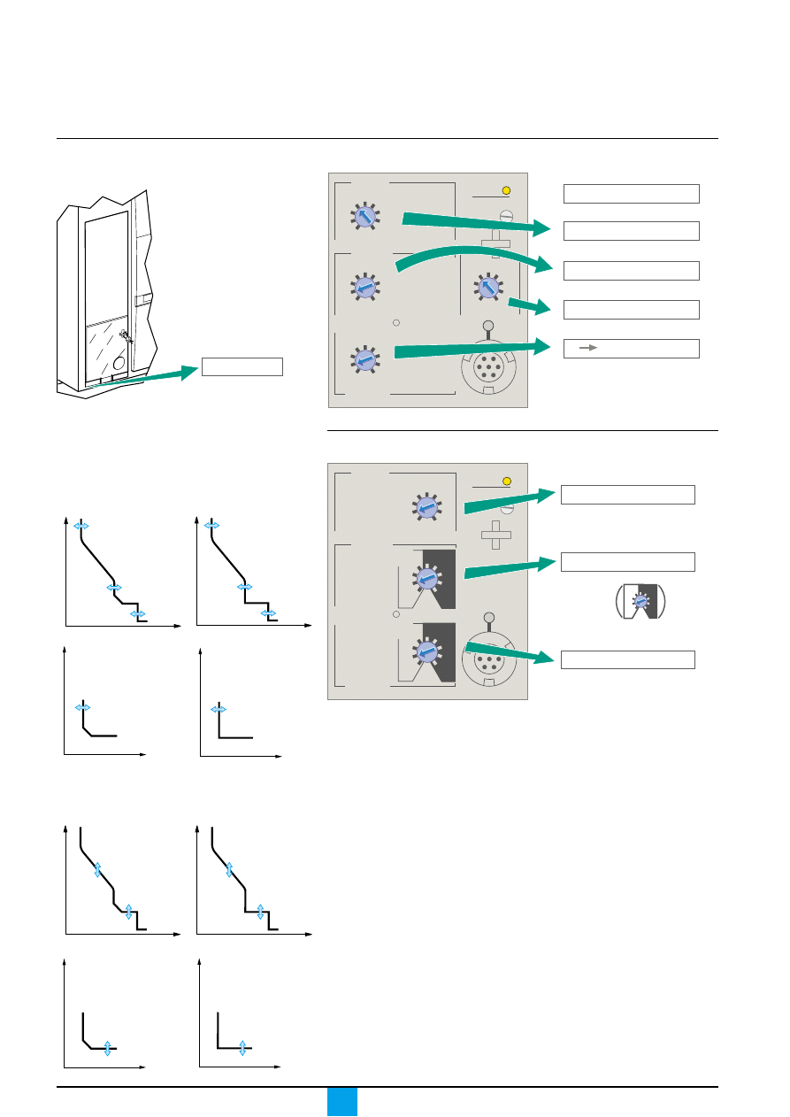
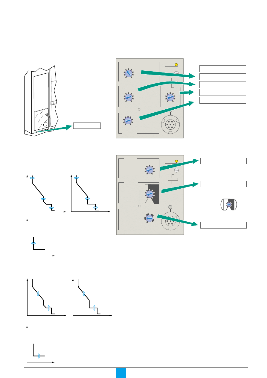
Micrologic 6.0 A
Micrologic 7.0 A
1. current setting Ir
(long time)
2. tripping delay tr
(long time) for 6 x Ir
3. pick-up Isd (short time)
4. tripping delay tsd
(short time)
5. pick-up Ii
(instantaneous)
1. pick-up Ig (earth fault)
2. tripping delay tg
(earth fault)
1. pick-up I
∆
n
(earth leakage)
2. tripping delay
∆
t
(earth leakage)
0
I
t
1
2
I
2
t off
I
2
t on
Ig
0
I
t
I
∆
n
1
2

Micrologic A
Schneider Electric
5
Short-time protection
c
the short-time protection function protects the distribution system against
impedant short-circuits
c
the short-time tripping delay can be used to ensure discrimination with a
downstream circuit breaker
c
this function carries out true rms measurements.
c
the I
2
t ON and I
2
t OFF options enhance discrimination with downstream
protection devices
c
use of I
2
t curves with short-time protection:
v
I
2
t OFF selected: the protection function implements a constant time curve;
v
I
2
t ON selected: the protection function implements an I
2
t inverse-time
curve up to 10 Ir. Above 10 Ir, the time curve is constant.
c
zone selective interlocking (ZSI)
The short-time and earth-fault protection functions enable time discrimination
by delaying the upstream devices to provide the downstream devices the time
required to clear the fault. Zone selective interlocking can be used to obtain total
discrimination between circuit breakers using external wiring.
Short-time pick-up Isd and tripping delay tsd
Micrologic control unit
2.0 A, 5.0 A, 6.0 A and 7.0 A
pick-up
Isd = Ir x …
1.5
2
2.5
3
4
5
6
8
10
accuracy
±
10 %
time delay
settings I
2
t OFF
0
0.1
0.2
0.3
0.4
(ms) at 10 Ir
I
2
t ON
0.1
0.2
0.3
0.4
I
2
t ON or
tsd (max resettable time)
20
80
140
230
350
I
2
t OFF
tsd (max break time)
80
140
200
320
500
Instantaneous protection
c
the instantaneous-protection function protects the distribution system
against solid short-circuits. Contrary to the short-time protection function,
the tripping delay for instantaneous protection is not adjustable.
The tripping order is sent to the circuit breaker as soon as current exceeds
the set value, with a fixed time delay of 20 milliseconds.
c
this function carries out true rms measurements.
Instantaneous pick-up Isd
Micrologic control unit
2.0 A
pick-up
Isd = Ir x …
1.5
2
2.5
3
4
5
6
8
10
accuracy
±
10 %
Instantaneous pick-up Ii
Micrologic control unit
5.0 A, 6.0 A and 7.0 A
pick-up
li = In x … (*)
2
3
4
6
8
10
12
15
OFF
accuracy
±
10 %
* In: circuit-breaker rating
For the characteristics and external wiring
of the zone selective interlocking function,
see the technical appendix on
"Zone selective interlocking".
The portable test kit can be used to test
the wiring between circuit breakers
for the zone selective interlocking function.

Micrologic A
Schneider Electric
6
Discovering your
control unit
Protection of the fourth pole on four-pole circuit breakers
Protection of the neutral conductor depends on the distribution system.
There are three possibilities.
Type of neutral
Description.
Neutral unprotected
The distribution system does not require protection
of the neutral conductor.
Neutral protection
The cross-sectional area of the neutral conductor
at 0.5 In
is half that of the phase conductors.
c
the long-time current setting Ir for the neutral is equal
to half the setting value
c
the short-time pick-up Isd for the neutral is equal
to half the setting value
c
the instantaneous pick-up Isd (Micrologic 2.0 A)
for the neutral is equal to half the setting value
c
the instantaneous pick-up Ii (Micrologic 5.0 A / 6.0 A /
7.0 A) for the neutral is equal to the setting value.
Neutral protection
The cross-sectional area of the neutral conductor is equal
at In
to that of the phase conductors.
c
the long-time current setting Ir for the neutral is equal
to the setting value
c
the short-time pick-up Isd for the neutral is equal to
the setting value
c
the instantaneous pick-ups Isd and Ii for the neutral
are equal to the setting value.
Overview of functions
Current protection
Earth-fault protection on Micrologic 6.0 A
c
an earth fault in the protection conductors can provoke local temperature rise
at the site of the fault or in the conductors.
The purpose of the earth-fault protection function is to eliminate this type of fault.
c
there are two types of earth-fault protection.
Type
Description
Residual
c
the function determines the zero-phase sequence
current, i.e. the vectorial sum of the phase and neutral
currents
c
it detects faults downstream of the circuit breaker.
Source Ground Return
c
using a special external sensor, this function
directly measures the fault current returning
to the transformer via the earth cable
c
it detects faults both upstream and downstream
of the circuit breaker
c
the maximum distance between the sensor
and the circuit breaker is ten metres.
c
earth-fault and neutral protection are independent and can therefore be
combined.
Earth-fault pick-up Ig and tripping delay tg
The pick-up and tripping-delay values can be set independently and are identical
for both the residual and "source ground return" earth-fault protection functions.
Micrologic control unit
6.0 A
pick-up
Ig = In x … (*)
A
B
C
D
E
F
G
H
I
accuracy
In
≤
400 A
0.3
0.3
0.4
0.5
0.6
0.7
0.8
0.9
1
±
10 %
400 A < In
≤
1200 A
0.2
0.3
0.4
0.5
0.6
0.7
0.8
0.9
1
In > 1200 A
500 A 640 A 720 A 800 A 880 A 960 A 1040 A
1120 A
1200 A
time delay
settings I
2
t OFF
0
0.1
0.2
0.3
0.4
(ms) at 10 In (*)
I
2
t ON
0.1
0.2
0.3
0.4
I
2
t ON or
tg (max resettable time)
20
80
140
230
350
I
2
t OFF
tg (max break time)
80
140
200
320
500
* In: circuit-breaker rating
Micrologic A
Schneider Electric
7
Current protection and alarms
Earth-leakage protection on Micrologic 7.0 A
c
the earth-leakage protection function primarily protects people against indirect
contact because an earth-leakage current can provoke an increase in the potential
of the exposed conductive parts. The earth-leakage pick-up value I
∆
n is displayed
directly in amperes and the tripping delay follows a constant-time curve
c
an external rectangular sensor is required for this function
c
this function is inoperative if the long-time rating plug is not installed
c
d
protected against nuisance tripping.
c
k
DC-component withstand class A up to 10 A.
Pick-up value I
∆
n and tripping delay
∆
t
Micrologic control unit
7.0 A
pick-up
I
∆
n
0.5
1
2
3
5
7
10
20
30
accuracy
0 to - 20 %
time delay
settings
(ms)
∆
t (max resettable time)
60
140
230
350
800
∆
t (max break time)
140
200
320
500
1000
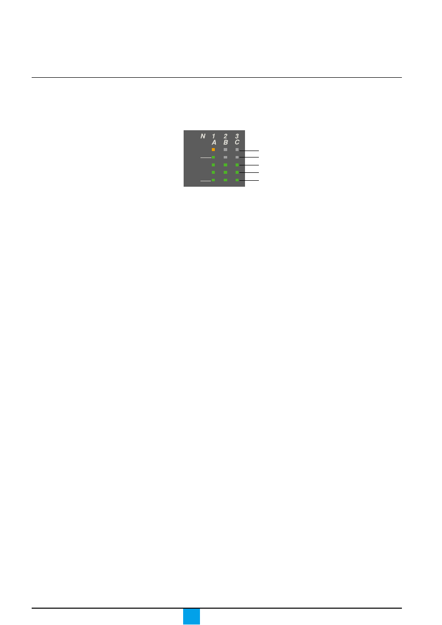
Overload LED
E51398A
This LED signals that the long-time current setting Ir has been overrun.
Fault indications
E51399A
E51400A
E51401A
E51402A
Signals tripping due to an
overrun of the long-time
current setting Ir.
Signals tripping due
to an overrun of the
short-time pick-up Isd
or the instantaneous
pick-up Isd / Ii.
Signals tripping due to an
overrun of the earth-fault
pick-up Ig or the earth-
leakage pick-up I
∆
n.
Signals tripping due to
the auto-protection
function of the control
unit.
delay
short time
I i
tsd
(s)
long time
alarm
test
800
earth leakage
1
2
3
5
7
10
20
30
∆
t
(ms)
60
.5
140
230
350
I
∆
n
(A)
setting
x Ir
2
2.5
3
4
5
6
8
10
Isd
1.5
on
I
2
t
.
2
.
3
.
4
.
4
.
1
.
2
.
3
.
1
0
x In
3
4
6
8 10
12
15
off
2
.5
1
2
4
8
12
16
20
tr
(s)
at 6 Ir
24
.4
.5
.6
.7
.8
.9
.95
.98
1
Ir
x In
instantaneous
40
%
%
100
Micrologic 7.0 A
Micrologic 7.0 A
Micrologic 7.0 A
Micrologic 7.0 A
The auto-protection function (excessive
temperature or short-circuit higher than
circuit-breaker capacity) opens the circuit
breaker and turns on the Ap LED.
Caution.
If the circuit breaker remains closed and
the Ap LED remains on, contact the
Schneider after-sales support department.
Caution.
The battery maintains the fault indications.
If there are no indications, check the
battery.
Micrologic A
Schneider Electric
8
Discovering your
control unit
Overview of functions
Ammeter measurements
c
all Micrologic control units measure the true rms value of currents
c
the most heavily loaded phase is continuously displayed on the digital screen
c
using the navigation buttons, it is possible to display successively the I1, I2, I3,
neutral IN, Ig, I
∆
N and stored-current (maximeter) values
c
the percent load on each phase is displayed. A bargraph displays the currents
measured on phases 1, 2 and 3 as a percentage of the long-time current setting Ir.
E60371A
40
%
%
100
1.125 x Ir
1 x Ir
0.8 x Ir
0.6 x Ir
0.4 x Ir
If no information is displayed on the screen,
see the technical appendix "Digital display".

Micrologic A
Schneider Electric
9
Micrologic A
Schneider Electric
10
Setting your control unit
Selecting the type
of neutral protection
On four-pole circuit breakers, it is possible to select the type of neutral protection
for the fourth pole:
c
neutral unprotected (4P 3D);
c
neutral protection at 0.5 In (3D + N/2);
c
neutral protection at In (4P 4D).
E51383A
4P 3D
3D+N/2
4P 4D
Micrologic A
Schneider Electric
11
Setting procedure
Setting procedure
1. Open the protective cover.
2. Select the desired
setting.
The set value is
automatically displayed
on the digital screen in
absolute value with the
relevant units.
c
Current in amperes
(A and kA);
c
Tripping delays in
seconds.
E51410A
E51411A
3. If no information is displayed, see the technical
appendix "Digital display". If no further action is taken,
after a few seconds, the display returns to the main
menu for current measurements.
4. Close the protective cover and, if necessary, install
a lead seal to protect the settings.
E51412A
Using the portable test kit
To test the control unit, connect the portable test kit via the test connector.
1
Micr
ologic 7.0 A
40
100 %
%
men
u
Micr
ologic 7.0 A
40
100 %
%
men
u
2
A
Ir=
3
Micr
ologic 7.0 A
40
100 %
%
men
u
E51413A
2
Micr
ologic 7.0 A
40
100 %
%
men
u
E51410A
1
Micr
ologic 7.0 A
40
100 %
%
men
u
See the user manual for the portable
test kit
Micrologic A
Schneider Electric
12
Setting your control unit
Setting the Micrologic 2.0 A
control unit
Set the threshold values
E51366A
E60365A
Set the tripping delay
The rating of the circuit breaker
in this example is 2000 A.
See pages 4 and 5 for information
on the available settings
E51368A
E60366A
E51370A
1
In = 2000 A
In = 2000 A
In = 2000 A
Ir = 0.7 x In = 1400 A
Isd = 3 x Ir = 4200 A
alarm
x Ir
2
2.5
3 4 5
6
8
10
1.5
setting
Isd
instantaneous
.4
.5
.6
.7
.8
.9
.95
.98
1
long time
Ir
x In
0
I
t
Ir
Isd
long time
alarm
.5
1
2
4
8
12
16
20
tr
(s)
at 6 Ir
24
tr = 1 second
0
I
t
tr
Micrologic A
Schneider Electric
13
Setting the Micrologic 5.0 A
control unit
Set the threshold values
E51366A
E60367A
Set the tripping delay
The rating of the circuit breaker
in this example is 2000 A.
See pages 4 and 5 for information
on the available settings
E60368A
In = 2000 A
Ir = 0.7 x In = 1400 A
Ii = 3 x In = 6000 A
Isd = 2 x Ir = 2800 A
.4
.5
.6
.7
.8
.9
.95
.98
1
setting
short time
I i
x Ir
2
2.5
3
4 5
6
8
10
Isd
1.5
long time
alarm
Ir
x In
x In
3
4
6
8 10
12
15
off
2
instantaneous
tr = 1 second
tsd = 0.2 seconds
short time
long time
alarm
.5
1
2
4
8 12
16
20
tr
(s)
at 6 Ir
24
delay
tsd
(s)
on
I
2
t
.
2
.
3
.
4
.
4
.
1
.
2
.
3
.
1
0
I
2
t on
I
2
t off
E51372A
E51373A
Ir
Isd
Ii
0
I
t
Ir
Isd
Ii
0
I
t
I
2
t
ON curve
I
2
t
OFF curve
1
In =
200
0 A
In = 2000 A
Thresholds
E51375A
E51376A
tr
tsd
0
I
t
tr
tsd
0
I
t
I
2
t
ON curve
I
2
t
OFF curve
Tripping delays
Micrologic A
Schneider Electric
14
Setting your control unit
Setting the Micrologic 6.0 A
control unit
Set the threshold values
E51366A
E51414A
The rating of the circuit breaker
in this example is 2000 A.
See pages 4 to 6 for information
on the available settings.
E51373A
E51372A
Ir
Isd
Ii
0
I
t
Ir
Isd
Ii
0
I
t
I
2
t
ON curve
I
2
t
OFF curve
Set the tripping delay
E60372A
E51376A
E51375A
tr
tsd
0
I
t
tr
tsd
0
I
t
E51416A
E51415A
E51419A
E51418A
0
I
t
tg
0
I
t
tg
1
In = 2000 A
In = 2000 A
short time
long time
alarm
ground fault
setting
.4
.5
.6
.7
.8
.9
.95
.98
1
Ir
x In
x Ir
2
2.5
3 4 5
6
8
10
Isd
1.5
B
C
D E F
G
H
I
Ig
A
I i
x In
3
4
6 8 10
12
15
off
2
In = 2000 A
Ir = 0.7 x In = 1400 A
Ii = 3 x In = 6000 A
Isd = 2 x Ir = 2800 A
B Ig = 640 A
instantaneous
test
0
I
t
Ig
0
I
t
Ig
short time
long time
alarm
ground fault
.5
1
2
4
8
12
16
20
tr
(s)
at 6 Ir
24
delay
tsd
(s)
on
I
2
t
.
2
.
3
.
4
.
4
.
2
.
3
.
1
0
off
tg
(s)
on
I
2
t
.
2
.
3
.
4
.
4
.
1
.
2
.
3
.
1
0
off
tr = 1 second
tsd = 0.2 seconds
tg = 0.2 seconds
I
2
t on
I
2
t off
.
1
test
Thresholds
Tripping delays
I
2
t
ON curve
I
2
t
OFF curve
Micrologic A
Schneider Electric
15
Setting the Micrologic 7.0 A
control unit
Set the threshold values
E51366A
E51420A
The rating of the circuit breaker
in this example is 2000 A.
See pages 4 to 7 for information
on the available settings.
Set the tripping delay
E60373A
1
In =
200
0 A
In = 2000 A
.4
.5
.6
.7
.8 .9
.95
.98
1
short time
I i
long time
alarm
Ir
x In
ground fault
setting
x Ir
2
2.5
3 4 5
6
8
10
Isd
1.5
x In
3
4
6
8 10
12
15
off
2
instantaneous
In = 2000 A
Ir = 0.7 x In = 1400 A
Ii = 3 x In = 6000 A
Isd = 2 x Ir = 2800 A
I
∆
n = 1 A
1
2
3 5 7
10
20
30
.5
I
∆
n
(A)
test
short time
long time
alarm
ground fault
.5
1
2
4
8
12
16
20
tr
(s)
at 6 Ir
24
delay
tsd
(s)
on
I
2
t
.
2
.
3
.
4
.
4
.
1
.
2
.
3
.
1
0
off
800
∆
t
(ms)
60
140
230
350
tr = 1 second
tsd = 0.2 seconds
∆
t = 140 milliseconds
I
2
t on
I
2
t off
test
I
2
t
OFF curve
E51373A
E51372A
Ir
Isd
Ii
0
I
t
Ir
Isd
Ii
0
I
t
I
2
t
ON curve
I
2
t
OFF curve
E51376A
E51375A
tr
tsd
0
I
t
tr
tsd
0
I
t
E51421A
E51423A
Thresholds
Tripping delays
I
2
t
ON curve
0
I
t
I
∆
n
0
I
t
∆
t
Micrologic A
Schneider Electric
16
Fault and status
indications
The procedure for closing the circuit
breaker following a fault trip is presented
in the circuit-breaker user manual.
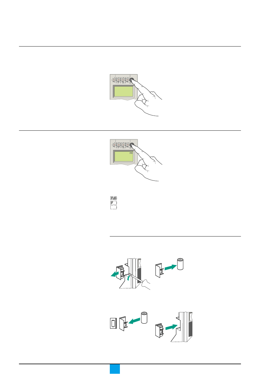
Resetting the fault indications
and checking battery status
If the battery needs to be changed, please
use the one with Schneider catalogue
number 33593 (characteristics given on the
battery compartment cover).
Resetting the fault indications
c
determine why the circuit breaker tripped.
The fault indication is maintained until it is reset on the control unit.
v
press the fault-trip reset button.
E51439A
v
check the parameter settings of the control unit.
Checking the battery
E51441A
Press the battery-test button (same as the fault-trip reset button) to display
the battery status.
If no information is displayed, either:
c
no battery is installed in the control unit, or;
c
an auxiliary power supply is required.
See the technical appendix "Digital display".
Changing the control-unit battery
1. Remove the battery
cover.
2. Remove the battery.
E51442A
E51443A
3. Insert a new battery.
Check the polarity.
4. Put the cover back in
place. Press the battery-
test button to check the
new battery.
E51444A
Micrologic 7.0 A
E51440A
Micrologic 7.0 A
Battery fully charged
Battery half charged
Change the battery
40
100 %
%
+
E51445A
40
100 %
%
Micrologic A
Schneider Electric
17
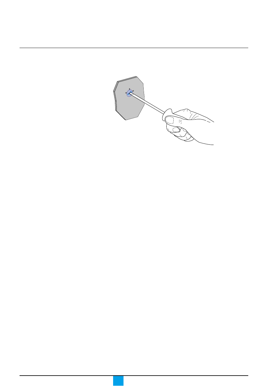
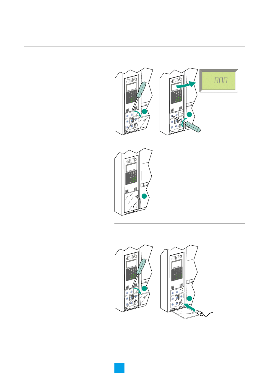
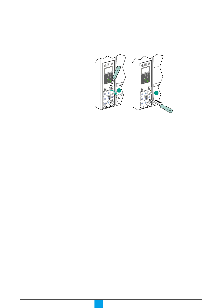
Testing the earth-fault and earth-
leakage functions
Charge and close the circuit breaker.
Using a screwdriver, press the test button for earth-fault and earth-leakage
protection. The circuit breaker should open.
E51410A
1
Micr
ologic 7.0 A
40
100 %
%
men
u
E51456A
Micr
ologic 7.0 A
40
100 %
%
men
u
2
If the circuit breaker does not open, contact the Schneider after-sales
support department.
Micrologic A
Schneider Electric
18
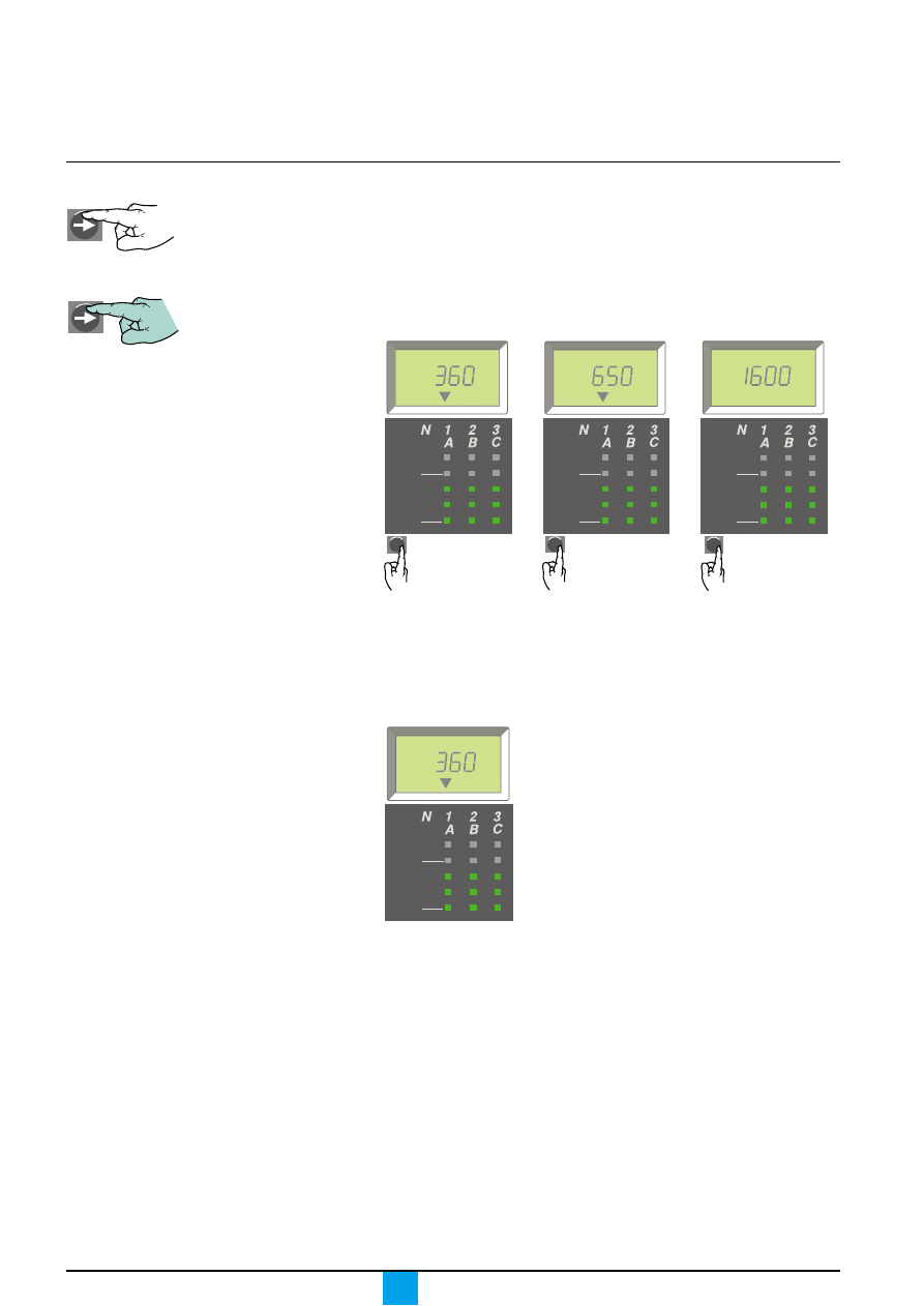
Accessing the menus
Symbols used:
Briefly press a key.
Press and hold a key.
E51404A
E51405A
It is possible at any time to stop consulting
a current measurement, a maximum
current value recorded by the maximeter or
the setting values. After a few seconds, the
Micrologic control unit automatically returns
to the main menu displaying the current
value of the most heavily loaded phase.
The protection settings can be displayed
directly on the digital display.
Three menus may be accessed on Micrologic control units, providing the following
information:
c
phase current measurements I1, I2, I3, neutral IN, earth-fault current Ig on the
Micrologic 6.0 A control unit and earth-leakage current I
∆
n on the Micrologic 7.0 A
control unit;
c
maximeter current values for phases I1, I2, I3, neutral IN, the maximum earth-
fault current Ig on the Micrologic 6.0 A control unit and the maximum earth-leakage
current I
∆
n on the Micrologic 7.0 A control unit;
c
protection settings and tripping delays.
Press the "menu" button
to access the maximum
current values measured
by the maximeter.
Press the "menu" button
to access the protection
settings and tripping
delays.
Press the "menu" button
to return to the current
measurements.
E51406A
E51407A
E51408A
4. The system returns
to the main
"Measurements" menu.
E51409A
40
100 %
%
A
menu
40
100 %
%
A
Max
menu
40
100 %
%
A
Ir=
menu
40
100 %
%
A
Menus
1. Measurements
2. Maximeter
3. Settings
Micrologic A
Schneider Electric
19
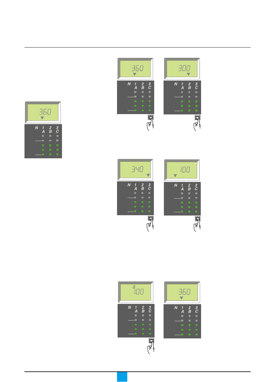
Current values may be read in the
"Measurements" menu, which is also the
main menu.
If no particular action is taken, the system
displays the current value of the most
heavily loaded phase.
E51409A
Measuring phase currents
Display of current I1.
Display of current I2.
E51425A
E51426A
Press the "arrow" button
to go on to current I2.
Press the "arrow" button
to go on to current I3.
Display of current I3.
Display of current Ig
(Micrologic 6.0 A) or
current I
∆
n
(Micrologic 7.0 A).
Press the "arrow" button
to go on to current IN if
the circuit breaker is
connected to the neutral.
E51427A
E51428A
Display of current IN.
The system returns to
the display of current I1.
E51429A
E51409A
40
100 %
%
A
40
100 %
%
A
40
100 %
%
A
40
100 %
%
A
40
100 %
%
A
40
100 %
%
A
40
100 %
%
A
Press the "arrow" button
to return to current I1.
"Measurements" menu
Phase 1 is the most heavily loaded.
Press the "arrow" button
to go on to the earth-fault
current Ig or the earth-
leakage current I
∆
n.
Micrologic A
Schneider Electric
20
Menus
Maximum current values may be read in
the "Maximeter" menu.
If no particular action is taken, the system
returns to the main menu.
E51407A
Displaying the maximum
current values
Display of the
maximum I1 current.
Display of the
maximum I2 current.
E51430A
E51431A
Press the "arrow" button
to go on to the maximum
I2 current.
Press the "arrow" button
to go on to the maximum
I3 current.
Display of the
maximum I3 current.
Press the "arrow" button
to go on to the maximum
earth-fault current Ig
(Micrologic 6.0 A) or the
maximum earth-leakage
current I
∆
n
(Micrologic 7.0 A)
Press the "arrow" button
to go on to the maximum
IN current if the circuit
breaker is connected to
the neutral.
E51432A
E51433A
Display of the
maximum IN current.
The system returns to
the display of the
maximum I1 current.
E51434A
E51435A
Press the "arrow" button
to return to the maximum
I1 current.
40
100 %
%
A
MAX
40
100 %
%
A
MAX
40
100 %
%
A
MAX
40
100 %
%
MAX
A
40
100 %
%
A
MAX
40
100 %
%
A
MAX
40
100 %
%
A
Max
menu
Display of the maximum
Ig current or the
maximum I
∆
n current.
"Maximeter" menu.
Micrologic A
Schneider Electric
21
Maximum current values can be reset
using the "Maximeter" menu.
If no particular action is taken, the system
returns to the main menu.
E51407A
Resetting the maximum current
values
Select the maximum
current value to be
reset (e.g. I2 max.).
Reset.
E51436A
E51437A
Press the "arrow" button
as many times as
required to select I2 max.
Press and hold the
"arrow" button down for
three to four seconds.
The current value flashes
during the reset, then
changes to the present
value (the new
maximum).
Select another value
to reset or return to
the main menu.
Press the "arrow" button
as many times as
required to select another
maximum value to reset
or return to the main
menu.
E51438A
40
100 %
%
A
Max
menu
40
100 %
%
A
MAX
40
100 %
%
A
MAX
40
100 %
%
A
MAX
"Maximeter" menu.
Micrologic A
Schneider Electric
22
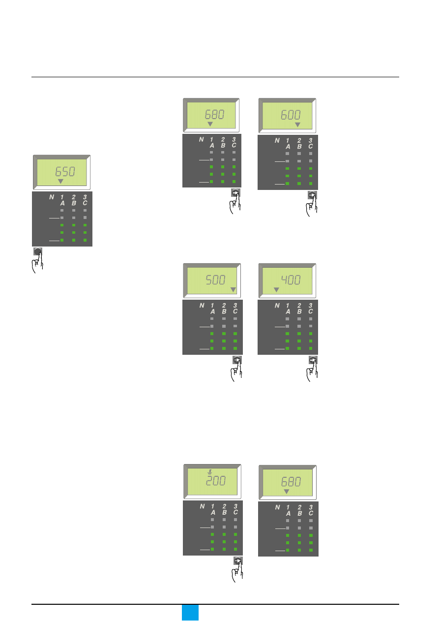
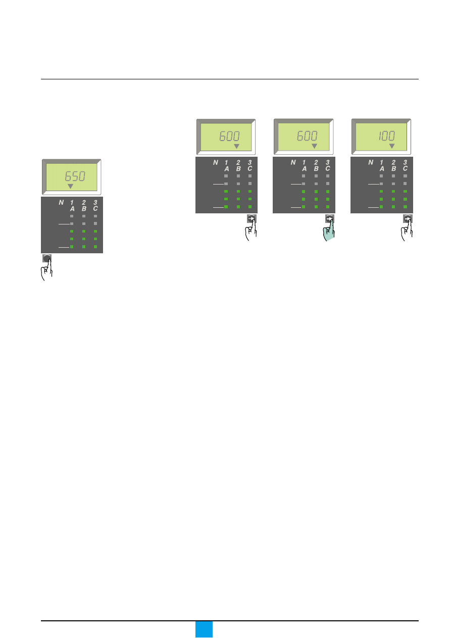
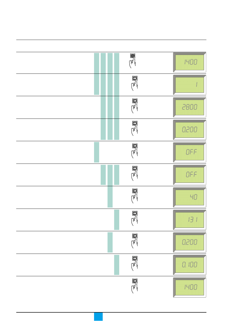
Menus
Viewing the settings
E60374A
Long-time current setting Ir
Long-time tripping delay tr
Short-time pick-up Isd
Short-time tripping delay tsd
Instantaneous pick-up Isd
Instantaneous pick-up Ii
Earth-fault pick-up Ig
Earth-leakage pick-up I
∆
n
Earth-fault tripping delay tg
Earth-leakage tripping delay
∆
t
Micrologic control unit
Select the "Settings"
menu.
The Ir value is the first
displayed.
Press the "arrow" button
to go on to the tr value.
Press the "arrow" button
to go on to the
short-time Isd value.
Press the "arrow" button
to go on to the tsd
value.
Press the "arrow" button
to go on to the
instantaneous Isd
value.
Or
Press the "arrow" button
to go on to the Ig value.
Or
Press the "arrow" button
to go on to the tg value.
Or
the
∆
t value.
Press the "arrow" button
to return to the
beginning of the menu.
the instantaneous Ii
value.
menu
A
s
tr=
A
Isd=
s
tsd=
A
Ig=
s
tg=
s
∆
t=
A
Ir=
Ii=
Ir=
Isd=
A
A
I
∆
n=
A
the I
∆
n value.
5.0 A 6.0 A 7.0 A
2.0 A

Micrologic A
Schneider Electric
23
Micrologic A
Schneider Electric
24
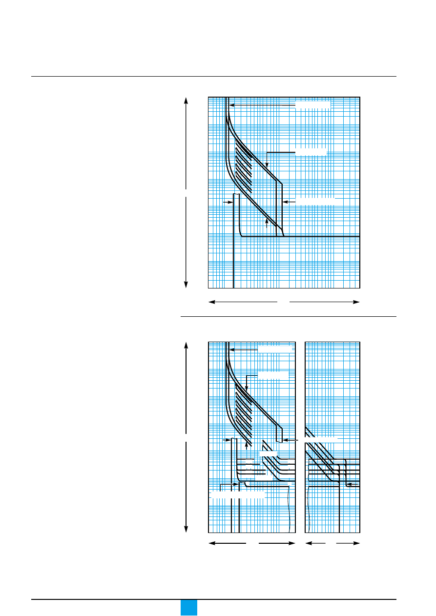
Technical appendix
Tripping curves
Long-time and instantaneous protection (Micrologic 2.0 A)
E60369A
.5 .7
1
2
3 4 5
7 10
20 30
50 70 100
200 300
I / Ir
10 000
5 000
2 000
1 000
500
200
100
50
20
10
5
2
1
.5
.2
.1
.05
.02
.01
.005
.002
.001
t(s)
tr = 0.5…24 s
Isd = 1.5…10 x Ir
Ir = 0.4…1 x In
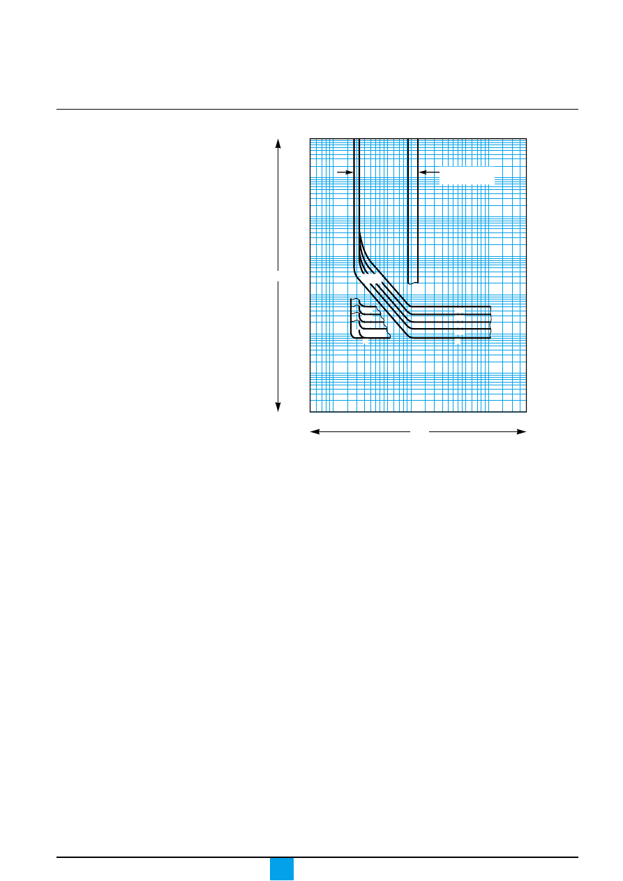
Long-time, short-time and instantaneous protection
(Micrologic 5.0 A, 6.0 A and 7.0 A)
E60370A
0
0.4
0.3
0.2
0.1
t(s)
.5 .7
1
2
3 4 5
7 10
20
3
5
7 10
20 30
10 000
5 000
2 000
1 000
500
200
100
50
20
10
5
2
1
.5
.2
.1
.05
.02
.01
.005
.002
.001
x In
tr = 0.5…24 s
Isd = 1.5…10 x Ir
Ir = 0.4…1 x In
Ii = 2…15 x In . OFF (1)
I
2
t OFF
x Ir
0.4
0.3
0.2
0. 1
I
2
t ON
0
Micrologic A
Schneider Electric
25
Earth-fault protection (Micrologic 6.0 A)
E46266A
Ig = A…J x In (1)
1200 A max.
t(s)
I / In
10 000
5 000
2 000
1 000
500
200
100
50
20
10
5
2
1
.5
.2
.1
.05
.02
.01
.005
.002
.001
.05.07 .1
.2
.3 .4 .5 .7 1
2
3
5
7 10
200 300
I
2
t OFF
0.4
0.3
0.2
0.1
I
2
t ON
0.4
0.3
0.2
0.1
0
0
Micrologic A
Schneider Electric
26
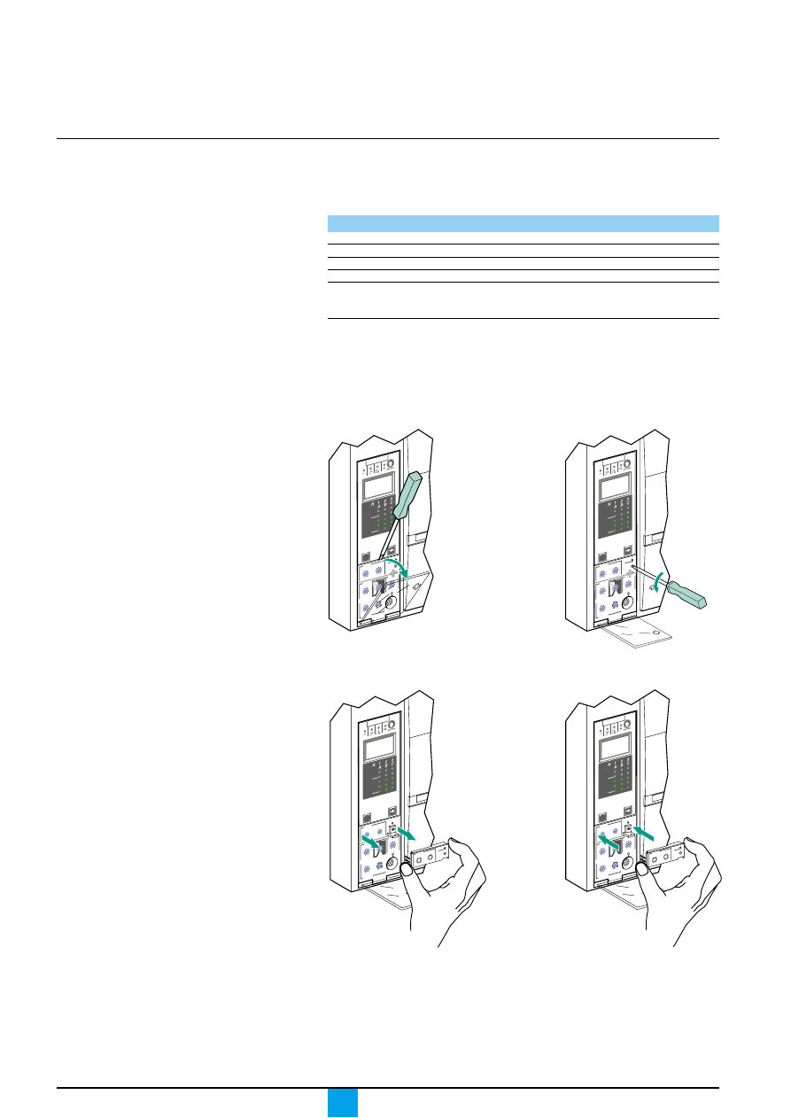
Technical appendix
Caution.
Following any modifications to the long-
time rating plug, all control-unit protection
parameters must be checked.
Changing the long-time
rating plug
Select the long-time rating plug
A number of setting ranges for the long-time current setting are available on
Micrologic A control units by changing the long-time rating plug.
The available rating plugs are listed below.
Part number
Setting range for the Ir value
33542
standard
0.4 to 1 x Ir
33543
low setting
0.4 to 0.8 x Ir
33544
high setting
0.8 to 1 x Ir
33545
without long-time protection
Change the long-time rating plug
Proceed in the following manner.
2. Open the protective
cover of the control unit.
3. Completely remove
the long-time rating plug screw.
E51378A
E51379A
4. Snap out the rating
plug.
5. Clip in the new rating plug.
E51380A
E51381A
6. Refit the screw for the
long-time rating plug.
7. Check and/or modify the
control-unit settings.
Caution.
If no long-time rating plug is installed, the
control unit continues to operate under the
following downgraded conditions:
c
the long-time current setting Ir is 0.4;
c
the long-time tripping delay tr
corresponds to the value indicated by the
adjustment dial;
c
the earth-leakage protection function is
disabled.
Micr
ologic 7.0 A
40
100 %
%
men
u
Micr
ologic 7.0 A
40
100 %
%
men
u
Micr
ologic 7.0 A
40
100 %
%
men
u
.4
.5
.6
.7
.8 .9
.95
.98
1
long
time
alarm
Ir
x In
.5
1
2
4
8 12
16
20
tr
(s)
@ 6
Ir
24
Micr
ologic 7.0 A
40
100 %
%
men
u
.4
.5
.6
.7
.8 .9
.95
.98
1
long
time
alarm
Ir
x In
.5
1
2
4
8 12
16
20
tr
(s)
@ 6
Ir
24
1. Open the circuit breaker.
Micrologic A
Schneider Electric
27
Caution.
If the protection function is not used on
circuit breakers equipped for ZSI
protection, a jumper must be installed to
short terminals Z3, Z4 and Z5.
If the jumper is not installed, the short-time
and earth-fault tripping delays are set
to zero, whatever the position of the
adjustment dial.
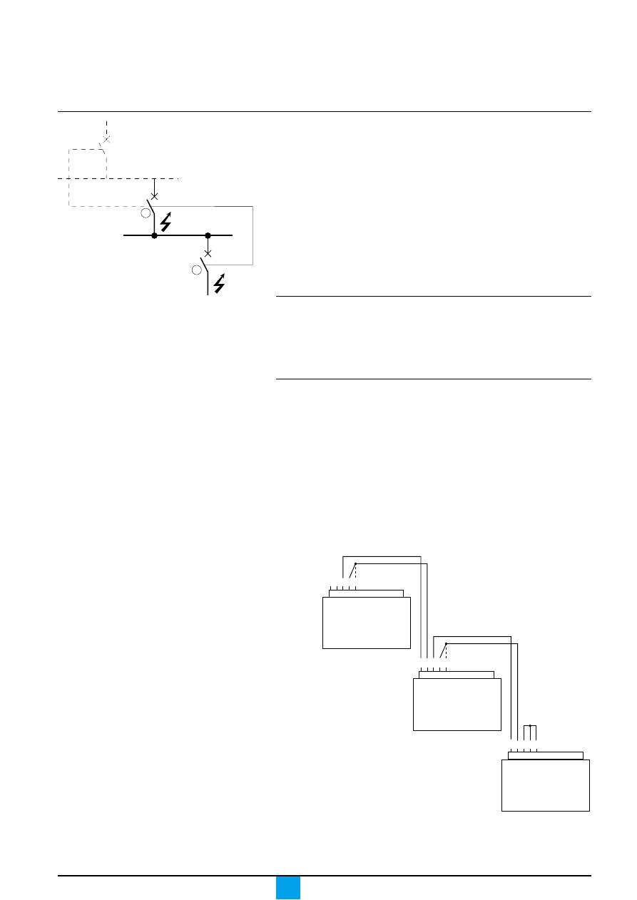
Zone selective interlocking (ZSI)
Operating principle
c
A fault occurs at point A.
Downstream device no. 2 clears the fault and sends a signal to upstream device
no. 1, which maintains the short-time tripping delay tsd or the earth-fault tripping
delay tg to which it is set.
c
A fault occurs at point B.
Upstream device no. 1 detects the fault. In the absence of a signal from a
downstream device, the upstream device immediately trips without taking into
account its tripping-delay settings. If it is connected to a device even further
upstream, it sends a signal to that device, which delays tripping according to its tsd
or tg setting.
Note :
On a circuit breaker likely to receive a ZSI signal, the tsd and tg tripping delays must not
be set to zero, as this would make discrimination impossible.
E51397A
A
B
1
2
Upstream
circuit breaker
Z1 Z2 Z3 Z4 Z5
Terminal block
for external
connections
Downstream
circuit breaker
Terminal block
for external
connections
and/or
and/or
Terminal block
for external
connections
Z1 Z2 Z3 Z4 Z5
Z1 Z2 Z3 Z4 Z5
E60375A
Connections between control units
A logic signal (0 or 5 volts) can be used for zone selective interlocking between the
upstream and downstream circuit breakers.
c
Micrologic 5.0 A, 6.0 A, 7.0 A.
c
Micrologic 5.0 P, 6.0 P, 7.0 P.
c
Micrologic 5.0 H, 6.0 H, 7.0 H.
Wiring
c
maximum impedance: 2.7
Ω
/ 300 metres
c
capacity of connectors: 0.4 to 2.5 mm
2
c
maximum cross-sectional area of wires (including insulation): 3.5 mm
2
c
wires: single or multicore
c
maximum length: 3000 metres
c
limits to device interconnection:
v
the common ZSI - OUT - SOURCE (Z1) and the output ZSI - OUT (Z2)
can be connected to a maximum of 10 inputs;
v
a maximum of 100 devices may be connected to an input ZSI IN CR (Z4) or GF
(Z5)
c
connections are made from the output ZSI - OUT (Z2) on the downstream device
to the input(s) ZSI - IN - ST (Z4) and/or GF (Z5) on the upstream device.
Terminals Z1 to Z5 correspond to the
identical indications on the circuit-breaker
terminal blocks.

Micrologic A
Schneider Electric
28
Technical appendix
Digital display
c
display of measurements operates without an external power supply.
The digital display goes off if the current drops below 0.2 x In (In = rated current).
c
display back-lighting is disabled in the following situations:
v
current less than 1 x In on one phase;
v
current less than 0.4 x In on two phases;
v
current less than 0.2 x In on three phases.
c
the maximeter does not operate for currents under 0.2 x In.
These three functions may be maintained by adding an external power supply.
Even if an external power supply is installed, the long-time, short-time,
instantaneous and earth protection functions will not use it.
For information on connecting an external
power supply, see the electrical diagrams
in the circuit-breaker user manual.

Micrologic A
Schneider Electric
29
Thermal memory
Thermal memory
The thermal memory is a means to simulate temperature rise and cooling caused
by changes in the flow of current in the conductors.
These changes may be caused by:
c
repetitive motor starting;
c
loads fluctuating near the protection settings;
c
repeated circuit-breaker closing on a fault.
Control units without a thermal memory (contrary to bimetal strip thermal
protection) do not react to the above types of overloads because they do not last
long enough to cause tripping. However, each overload produces a temperature
rise and the cumulative effect can lead to dangerous overheating.
Control units with a thermal memory record the temperature rise caused by each
overload. Even very short overloads produce a temperature rise that is stored in
the memory.
This information stored in the thermal memory reduces the tripping time.
Micrologic control units and thermal memory
All Micrologic control units are equipped as standard with a thermal memory
c
for all protection functions, prior to tripping, the temperature-rise and cooling time
constants are equal and depend on the tripping delay in question:
v
if the tripping delay is short, the time constant is low;
v
if the tripping delay is long, the time constant is high.
c
for long-time protection, following tripping, the cooling curve is simulated by the
control unit. Closing of the circuit breaker prior to the end of the time constant
(approximately 15 minutes) reduces the tripping time indicated in the tripping
curves.

Schneider Electric Industries SA
Designed by: HeadLines
Printed by:
As standards, specifications and designs develop from time, always ask for confirmation of the
information given in this publication.
5, rue Nadar
92506 Rueil-Malmaison Cedex
France
Tel: +33 (0)1 41 29 82 00
Fax:+33 (0)1 47 51 80 20
http://www.schneiderelectric.com
04443724AA-A
11-99
This document has been printed on ecological paper.
Wyszukiwarka
Podobne podstrony:
05 MICROLOGIC 2 0A 7 0A MANUAL
PANsound manual
als manual RZ5IUSXZX237ENPGWFIN Nieznany
hplj 5p 6p service manual vhnlwmi5rxab6ao6bivsrdhllvztpnnomgxi2ma vhnlwmi5rxab6ao6bivsrdhllvztpnnomg
BSAVA Manual of Rabbit Surgery Dentistry and Imaging
Okidata Okipage 14e Parts Manual
Bmw 01 94 Business Mid Radio Owners Manual
Manual Acer TravelMate 2430 US EN
manual mechanika 2 2 id 279133 Nieznany
4 Steyr Operation and Maintenance Manual 8th edition Feb 08
Oberheim Prommer Service Manual
cas test platform user manual
Kyocera FS 1010 Parts Manual
juki DDL 5550 DDL 8500 DDL 8700 manual
Forex Online Manual For Successful Trading
ManualHandlingStandingAssessment
więcej podobnych podstron