
Firewall Filters
Document revision 1.10 (Sun Dec 05 12:41:37 GMT 2004)
This document applies to MikroTik RouterOS V2.8
Table of Contents
Table of Contents
General Information
Summary
Quick Setup Guide
Specifications
Related Documents
Description
Packet Flow
Description
Firewall Rules
Description
Property Description
Notes
Example
Firewall Chains
Description
Notes
Example
IP Firewall Applications
Description
Example of Firewall Filters
Protecting the Customer's Network
Enforcing the 'Internet Policy'
Example of Source NAT (Masquerading)
Example of Destination NAT
General Information
Summary
The firewall implements packet filtering and thereby provides security functions that are used to
manage data flow to, from and through the router. Along with the Network Address Translation it
serve as a tool for preventing unauthorized access to directly attached networks and the router itself
as well as a filter for outgoing traffic.
Quick Setup Guide
•
To add a firewall rule which drops all TCP packets that are destined to port 135 and going
through the router, use the following command:
/ip firewall rule forward add dst-port=135 protocol=tcp action=drop
Page 1 of 13

•
To deny acces to router via Telnet (protocol TCP, port 23), type the following command:
/ip firewall rule input add protocol=tcp dst-port=23 action=drop
Specifications
Packages required: system
License required: level1 (P2P filters limited to 1), level3
Home menu level: /ip firewall
Standards and Technologies:
IP
Hardware usage: Increases with filtering rules count
Related Documents
•
Package Management
•
IP Addresses and ARP
•
Routes, Equal Cost Multipath Routing, Policy Routing
•
Network Address Translation
•
Packet Marking (Mangle)
Description
Network firewalls keep outside threats away from sensitive data available inside the network.
Whenever different networks are joined together, there is always a threat that someone from outside
of your network will break into your LAN. Such break-ins may result in private data being stolen
and distributed, valuable data being altered or destroyed, or entire hard drives being erased.
Firewalls are used as a means of preventing or minimizing the security risks inherent in connecting
to other networks. MikroTik RouterOS implements wide firewalling features as well as
masquerading capabilities, which allows you to hide your network infrastructure from the outside
world.
Packet Flow
Description
MikroTik RouterOS simplifies the creation and deployment of sophisticated firewall policies. In
fact, you can easily create a simple one to filter your traffic or enable source NAT without need to
know how packets are processed in the router. But in case you want to deploy more complicated
policies, it is worth to know the underlying process details. IP packet flow through the router is
depicted in the following diagram:
Page 2 of 13
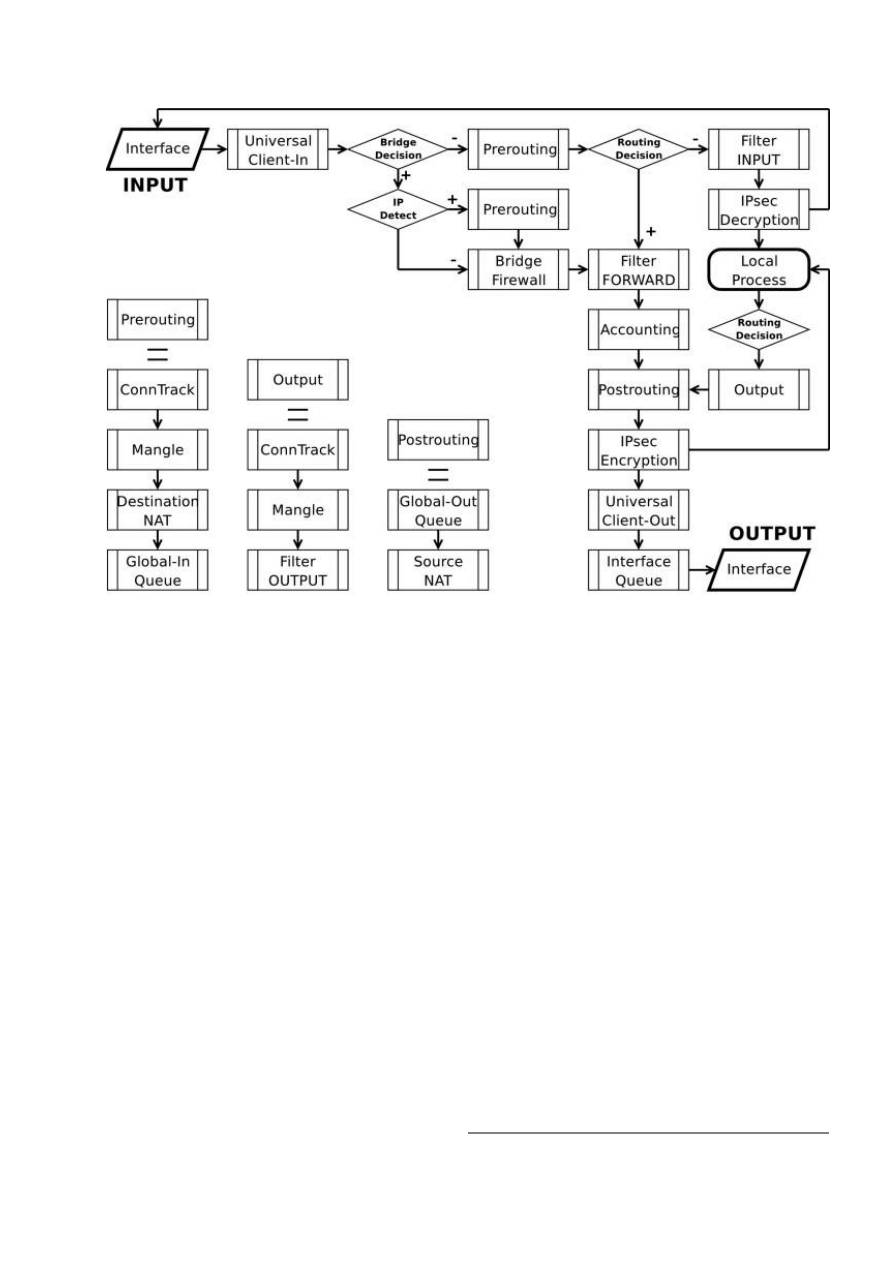
As we can see, a packet can enter the conveyer in two ways: whether the packet has come from an
interface or whether it has been originated by the router. Analogically, a packet has two ways to
leave the conveyer: through an outgoing interface or, in case the packet is locally destined, in the
local process.
When the packet arrives to the router's interface, firewall rules are applied in the following order:
•
The NAT rules are applied first. The firewall rules of the input chain and routing are applied
after the packet has passed the NAT rule set.
•
If the packet should be forwarded through the router, the firewall rules of the forward chain are
applied next.
•
When a packet leaves an interface, firewall rules of the output chain are applied first, then the
NAT rules and queuing.
Additional arrows from IPsec boxes shows the processing of encrypted packets (they need to be
encrypted / decrypted first and then processed as usual, id est from the point an ordinal packet
enters the router).
If the packet is bridged one, the 'Routing Decision' changes to 'Bridge Forwarding Decision'. In case
the bridge is forwarding non-IP packets, all things regarding IP protocol are not applicable
('Universal Client', 'Conntrack', 'Mangle', et cetera).
Firewall Rules
Home menu level: /ip firewall rule <chain name>
Page 3 of 13

Description
A rule is an expression in a definite form that tells the router what to do with a particular packet.
The rule consists of two logical parts: the matcher set and the action set. For each packet you need
to define a rule with appropriate match and action.
Management of the firewall rules can be accessed by selecting the desired chain. If you use the
WinBox console, select the desired chain and then press the List button on the toolbar to open the
window with the rules.
Peer-to-Peer Traffic Filtering
MikroTik RouterOS provides a way to filter traffic from most popular peer-to-peer programs that
uses different P2P protocols.
ICMP TYPE:CODE values
In order to protect your router and attached private networks, you need to configure firewall to drop
or reject most of ICMP traffic. However, some ICMP packets are vital to maintain network
reliability or provide troubleshooting services.
The following is a list of ICMP TYPE:CODE values found in good packets. It is generally
suggested to allow these types of ICMP traffic.
• • 8:0 - echo request
• 0:0 - echo reply
Ping
• • 11:0 - TTL exceeded
• 3:3 - Port unreachable
Trace
• • 3:4 - Fragmentation-DF-Set
Path MTU discovery
General suggestion to apply ICMP filtering
•
Allow ping—ICMP Echo-Request outbound and Echo-Reply messages inbound
•
Allow traceroute—TTL-Exceeded and Port-Unreachable messages inbound
•
Allow path MTU—ICMP Fragmentation-DF-Set messages inbound
•
Block everything else
Type of Service
Internet paths vary in quality of service they provide. They can differ in cost, reliability, delay and
throughput. This situation imposes some tradeoffs, exempli gratia the path with the lowest delay
Page 4 of 13

may be among the slowest. Therefore, the "optimal" path for a packet to follow through the Internet
may depend on the needs of the application and its user.
Because the network itself has no knowledge on how to optimize path choosing for a particular
application or user, the IP protocol provides a facility for upper layer protocols to convey hints to
the Internet Layer about how the tradeoffs should be made for the particular packet. This facility is
called the "Type of Service" facility.
The fundamental rule is that if a host makes appropriate use of the TOS facility, its network service
should be at least as good as it would have been if the host had not used this facility.
Type of Service (ToS) is a standard field of IP packet and it is used by many network applications
and hardware to specify how the traffic should be treated by the gateway.
MikroTik RouterOS works with the full ToS byte. It does not take account of reserverd bits in this
byte (because they have been redefined many times and this approach provides more flexibility). It
means that it is possible to work with DiffServ marks (Differentiated Services Codepoint, DSCP as
defined in RFC2474) and ECN codepoints (Explicit Congestion Notification, ECN as defined in
RFC3168), which are using the same field in IP protocol header. Note that it does not mean that
RouterOS supports DiffServ or ECN, it is just possible to access and change the marks used by
these protocols.
RFC1349 defines these standard values:
• normal - normal service (ToS=0)
• low-cost - minimize monetary cost (ToS=2)
• max-reliability - maximize reliability (ToS=4)
• max-throughput - maximize throughput (ToS=8)
• low-delay - minimize delay (ToS=16)
Property Description
action (accept | drop | jump | passthrough | reject | return; default: accept) - action to undertake if
the packet matches the rule, one of the:
• accept - accept the packet. No action, i.e., the packet is passed through without undertaking any
action, except for mangle, and no more rules are processed in the relevant list/chain
• drop - silently drop the packet (without sending the ICMP reject message)
• jump - jump to the chain specified by the value of the jump-target argument
• passthrough - ignore this rule, except for mangle, go on to the next one. Acts the same way as
a disabled rule, except for ability to count and mangle packets
• reject - reject the packet and send an ICMP reject message
• return - return to the previous chain, from where the jump took place
comment (text; default: "") - a descriptive comment for the rule
connection (text; default: "") - connection mark to match. Only connections (including related)
marked in the MANGLE would be matched
connection-limit (integer; default: 0) - match the number of concurrent connections from each
particular IP address
connection-state (any | established | invalid | new | related; default: any) - connection state
Page 5 of 13

content (text; default: "") - the text packets should contain in order to match the rule
disabled (yes | no; default: no) - specifies whether the rule is disabled or not
dst-address (IP address/mask:port; default: 0.0.0.0/0:0-65535) - destination IP address
dst-netmask (IP address) - destination netmask in decimal form x.x.x.x
dst-port (integer: 0..65535) - destination port number or range
• 0 - all ports 1-65535
flow (text) - flow mark to match. Only packets marked in the MANGLE would be matched
icmp-options (integer; default: any:any) - matches ICMP Type:Code fields
in-interface (name; default: all) - interface the packet has entered the router through.
• all - may include the local loopback interface for packets originated from the router
jump-target (name) - name of the target chain, if the action=jump is used
limit-burst (integer; default: 0) - allowed burst regarding the limit-count/limit-time, measuret in
bits/s
limit-count (integer; default: 0) - how many times to use the rule during the limit-time period
limit-time (time; default: 0) - time interval measured in seconds, used in conjunction with
limit-count
• 0 - forever
log (yes | no; default: no) - specifies to log the action or not
out-interface (name; default: name) - interface the packet is leaving the router from
• all - may include the local loopback interface for packets with destination to the router
p2p (any | all-p2p | bit-torrent | direct-connect | fasttrack | soulseek | blubster | edonkey | gnutella |
warez; default: any) - match Peer-to-Peer (P2P) connections:
• all-p2p - match all known P2P traffic
• any - match any packet (i.e., do not check this property)
protocol (ah | egp | ggp | icmp | ipencap | ospf | rspf | udp | xtp | all | encap | gre | idpr-cmtp | ipip |
pup | st | vmtp | ddp | esp | hmp | igmp | iso-tp4 | rdp | tcp | xns-idp; default: all) - protocol setting
• all - cannot be used, if you want to specify ports
src-address (IP address/mask:port; default: 0.0.0.0/0:0-65535) - source IP address
src-mac-address (MAC address; default: 00:00:00:00:00:00) - host's MAC address the packet has
been received from
src-netmask (IP address) - source netmask in decimal form x.x.x.x
src-port (integer: 0..65535) - source port number or range (0-65535)
• 0 - all ports 1-65535
tcp-options (any | syn-only | non-syn-only; default: any) - TCP options
tos (<integer> | dont-change | low-cost | low-delay | max-reliability | max-throughput | normal | any
| integer; default: any) - specifies a match to the value of Type of Service (ToS) field of IP header:
• any - match any packet (i.e., do not check this property)
Notes
Page 6 of 13

Keep in mind, that protocol must be explicity specified, if you want to select port.
Example
For instance, we want to reject packets with dst-port=8080:
/ip firewall rule input add dst-port=8080 protocol=tcp action=reject
[admin@MikroTik] ip firewall rule input> print
Flags: X - disabled, I - invalid
0
src-address=0.0.0.0/0:0-65535 in-interface=all
dst-address=0.0.0.0/0:8080 out-interface=all protocol=tcp
icmp-options=any:any tcp-options=any connection-state=any flow=""
sconnection="" content="" rc-mac-address=00:00:00:00:00:00 limit-count=0
limit-burst=0 limit-time=0s action=reject log=no
To allow not more than 4 concurrent connection from each particular IP address, you can use this
rule:
/ip firewall rule forward add protocol=tcp tcp-options=syn-only connection-limit=5 \
action=drop
Firewall Chains
Home menu level: /ip firewall
Description
The firewall filtering rules are grouped together in chains. It allows a packets to be matched against
one common criterion in one chain, and then passed over for processing against some other
common criteria to another chain. Let us assume that, for example, packets must be matched against
the IP addresses and ports. Then matching against the IP addresses can be done in one chain
without specifying the protocol ports. Matching against the protocol ports can be done in a separate
chain without specifying the IP addresses.
There are three predefined chains, which cannot be deleted:
•
The chain input is used to process packets entering the router through one of the interfaces
with the destination of the router. Packets passing through the router are not processed against
the rules of the input chain.
•
The chain forward is used to process packets passing through the router.
•
The chain output is used to process packets originated from the router and leaving it through
one of the interfaces. Packets passing through the router are not processed against the rules of
the output chain.
When processing a chain, rules are taken from the chain in the order they are listed there from top to
bottom. If a packet matches the criteria of the rule, then the specified action is performed on it, and
no more rules are processed in that chain. If the packet has not matched any rule within the chain,
then the default policy action of the chain is performed.
Available default policy actions include:
• accept - accept the packet
• drop - silently drop the packet (without sending the ICMP reject message)
Page 7 of 13

• none - not applicable
Usually packets should be matched against several criteria. More general filtering rules can be
grouped together in a separate chain. To process the rules of additional chains, the jump action
should be used with destination to this chain from a rule within another chain.
The policy of user added chains is none, and it cannot be changed. Chains cannot be removed, if
they contain rules (are not empty).
Notes
Because the NAT rules are applied first, it is important to hold this in mind when setting up firewall
rules, since the original packets might be already modified by the NAT.
The packets passing through the router are not processed against the rules of neither the input, nor
output chains.
Be careful about changing the default policy action to input and output chains! You may lose the
connection to the router, if you change the policy to drop, and there are no additional rules that
allow connection to the router.
Example
[admin@MikroTik] ip firewall> print
# NAME
POLICY
0 input
accept
1 forward
accept
2 output
accept
[admin@MikroTik] ip firewall> add name=router
[admin@MikroTik] ip firewall> print
# NAME
POLICY
0 input
accept
1 forward
accept
2 output
accept
3 router
none
IP Firewall Applications
Description
In this section some IP firewalling common applications and examples of them are discussed.
Basic Firewall Building Principles
Assume we have a router that connects a customer's network to the Internet. The basic firewall
building principles can be grouped as follows:
•
Protect the router from unauthorized access
Connections to the addresses assigned to the router itself should be monitored. Only access
from certain hosts to certain TCP ports of the router should be allowed.
This can be done by putting rules in the input chain to match packets with the destination
address of the router entering the router through all interfaces.
•
Protect the customer's hosts
Page 8 of 13

Connections to the addresses assigned to the customer's network should be monitored. Only
access to certain hosts and services should be allowed.
This can be done by putting rules in the forward chain to match packets passing through the
router with the destination addresses of customer's network.
•
Use source NAT (masquerading) to 'Hide' the Private Network behind one External
Address
All connections form the private addresses are masqueraded, and appear as coming from one
external address - that of the router.
This can be done by enabling the masquerading action for source NAT rules.
•
Enforce the Internet Usage Policy from the Customer's Network
Connections from the customer's network should be monitored.
This can be done by putting rules in the forward chain, or/and by masquerading (source NAT)
only those connections, that are allowed.
Filtering has some impact on the router's performance. To minimize it, the filtering rules that match
packets for established connections should be placed on top of the chain. These are TCP packets
with options non-syn-only.
Examples of setting up firewalls are discussed below.
Example of Firewall Filters
Assume we want to create a firewall that:
•
protects the MikroTik router from unauthorized access from anywhere. Only access from the
'trusted' network 10.5.8.0/24 is allowed
•
protects the customer's hosts within the network 192.168.0.0/24 from unauthorized access
from anywhere
•
gives access from the Internet to the http and smtp services on 192.168.0.17
•
allows only ICMP ping from all customer's hosts and forces use of the proxy server on
192.168.0.17
The basic network setup is illustraded in the following diagram:
Page 9 of 13
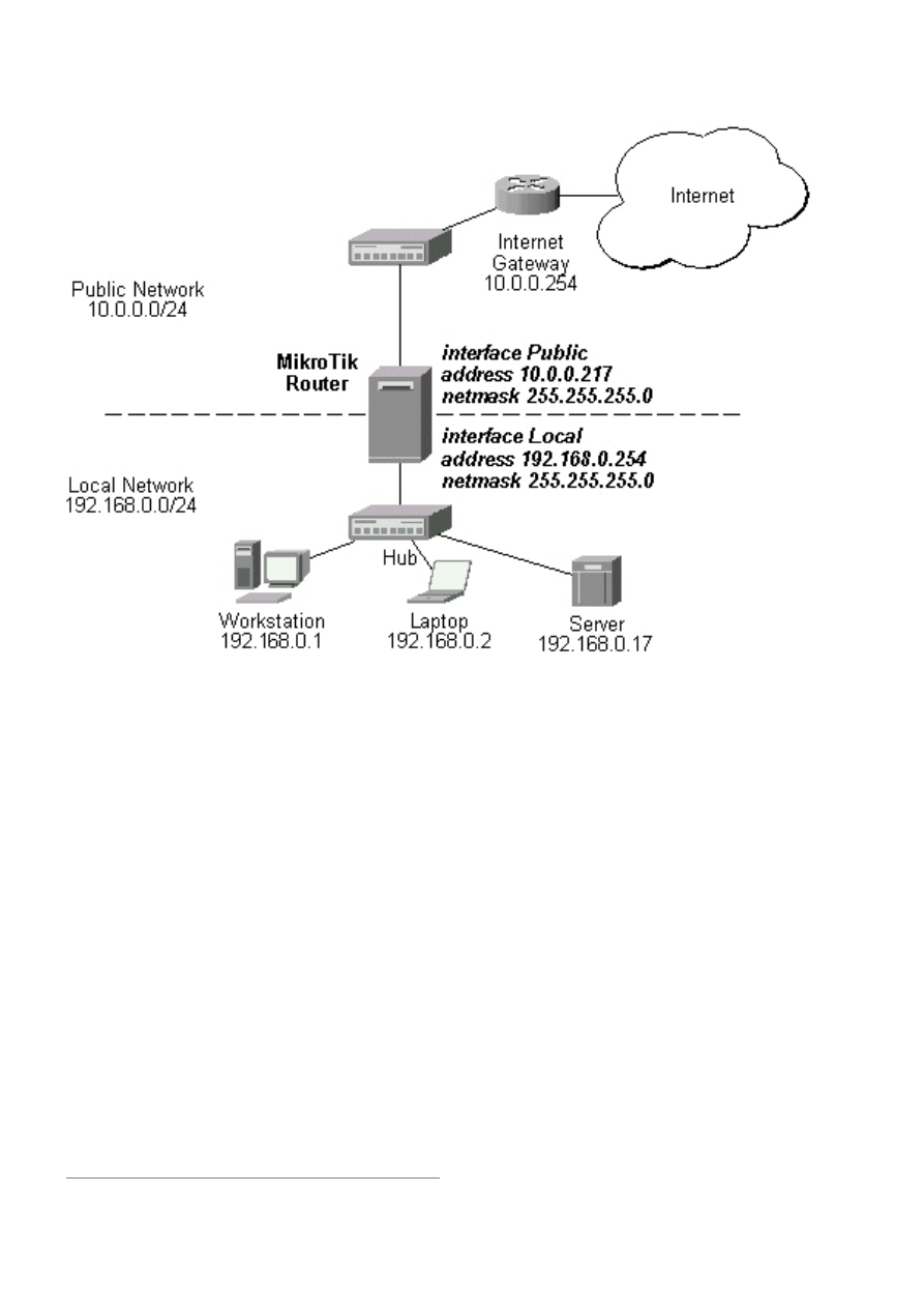
The IP addresses and routes of the MikroTik router are as follows:
[admin@MikroTik] ip address> print
Flags: X - disabled, I - invalid, D - dynamic
#
ADDRESS
NETWORK
BROADCAST
INTERFACE
0
10.0.0.217/24
10.0.0.0
10.0.0.255
Public
1
192.168.0.254/24
192.168.0.0
192.168.0.255
Local
[admin@MikroTik] ip route> print
Flags: X - disabled, I - invalid, D - dynamic, J - rejected,
C - connect, S - static, R - rip, O - ospf, B - bgp
#
DST-ADDRESS
G GATEWAY
DISTANCE INTERFACE
0
S 0.0.0.0/0
r 10.0.0.254
1
Public
1 DC 192.168.0.0/24
r 0.0.0.0
0
Local
2 DC 10.0.0.0/24
r 0.0.0.0
0
Public
To protect the router from unauthorized access, we should filter out all packets with the destination
addresses of the router, and accept only those which are allowed. Since all packets with destination
to the router's address are processed against the input chain, we can add the following rules to it:
/ip firewall rule input
add connection-state=invalid action=drop \
comment="Drop invalid connection packets"
add connection-state=established \
comment="Allow established connections"
add connection-state=related \
comment="Allow related connections"
add protocol=udp comment="Allow UDP connections"
add protocol=icmp comment="Allow ICMP messages"
add src-addr=10.5.8.0/24 \
comment="Allow access from 'trusted' network 10.5.8.0/24"
add action=drop log=yes \
Page 10 of 13

comment="Reject and log everything else"
Thus, the input chain will accept only allowed connections and drop, and log everything else.
Protecting the Customer's Network
To protect the customer's network, we should match all packets with destination address
192.168.0.0/24 that are passing through the router. This can be done in the forward chain. We can
match the packets against the IP addresses in the forward chain, and then jump to another chain,
say, customer. We create the new chain and add rules to it:
/ip firewall add name=customer
/ip firewall rule customer
add connection-state=invalid action=drop \
comment="Drop invalid connection packets"
add connection-state=established \
comment="Allow established connections"
add connection-state=related \
comment="Allow related connections"
add protocol=udp \
comment="Allow UDP connections"
add protocol=icmp \
comment="Allow ICMP messages"
add protocol=tcp dst-address=192.168.0.17/32:80 \
comment="Allow http connections to the server at 192.168.0.17"
add protocol=tcp dst-address=192.168.0.17/32:25 \
comment="Allow SMTP connections to the server at 192.168.0.17"
add action=drop log=yes comment="Drop and log everything else"
All we have to do now is to put rules in the forward chain, that match the IP addresses of the
customer's hosts on the Local interface and jump to the customer chain:
/ip firewall rule forward
add out-interface=Local action=jump \
jump-target=customer
Thus, everything that passes the router and leaves the Local interface (destination of the customer's
network) will be processed against the firewall rules of the customer chain.
Enforcing the 'Internet Policy'
To force the customer's hosts to access the Internet only through the proxy server at 192.168.0.17,
we should put following rules in the forward chain:
/ip firewall rule forward
add connection-state=invalid action=drop \
comment="Drop invalid connection packets"
add connection-state=established \
comment="Allow established connections"
add connection-state=related \
comment="Allow related connections"
add protocol=icmp out-interface=Public \
comment="Allow ICMP ping packets"
add src-address=192.168.0.17/32 out-interface=Public \
comment="Allow outgoing connections from the server at 192.168.0.17"
add action=drop out-interface=Public log=yes \
comment="Drop and log everything else"
Example of Source NAT (Masquerading)
If you want to "hide" the private LAN 192.168.0.0/24 "behind" one address 10.0.0.217 given to you
Page 11 of 13
by the ISP (see the network diagram in the Application Example above), you should use the source
network address translation (masquerading) feature of the MikroTik router. The masquerading will
change the source IP address and port of the packets originated from the network 192.168.0.0/24 to
the address 10.0.0.217 of the router when the packet is routed through it.
To use masquerading, a source NAT rule with action 'masquerade' should be added to the firewall
configuration:
/ip firewall src-nat action=masquerade out-interface=Public
All outgoing connections from the network 192.168.0.0/24 will have source address 10.0.0.217 of
the router and source port above 1024. No access from the Internet will be possible to the Local
addresses. If you want to allow connections to the server on the local network, you should use
destination Network Address Translation (NAT).
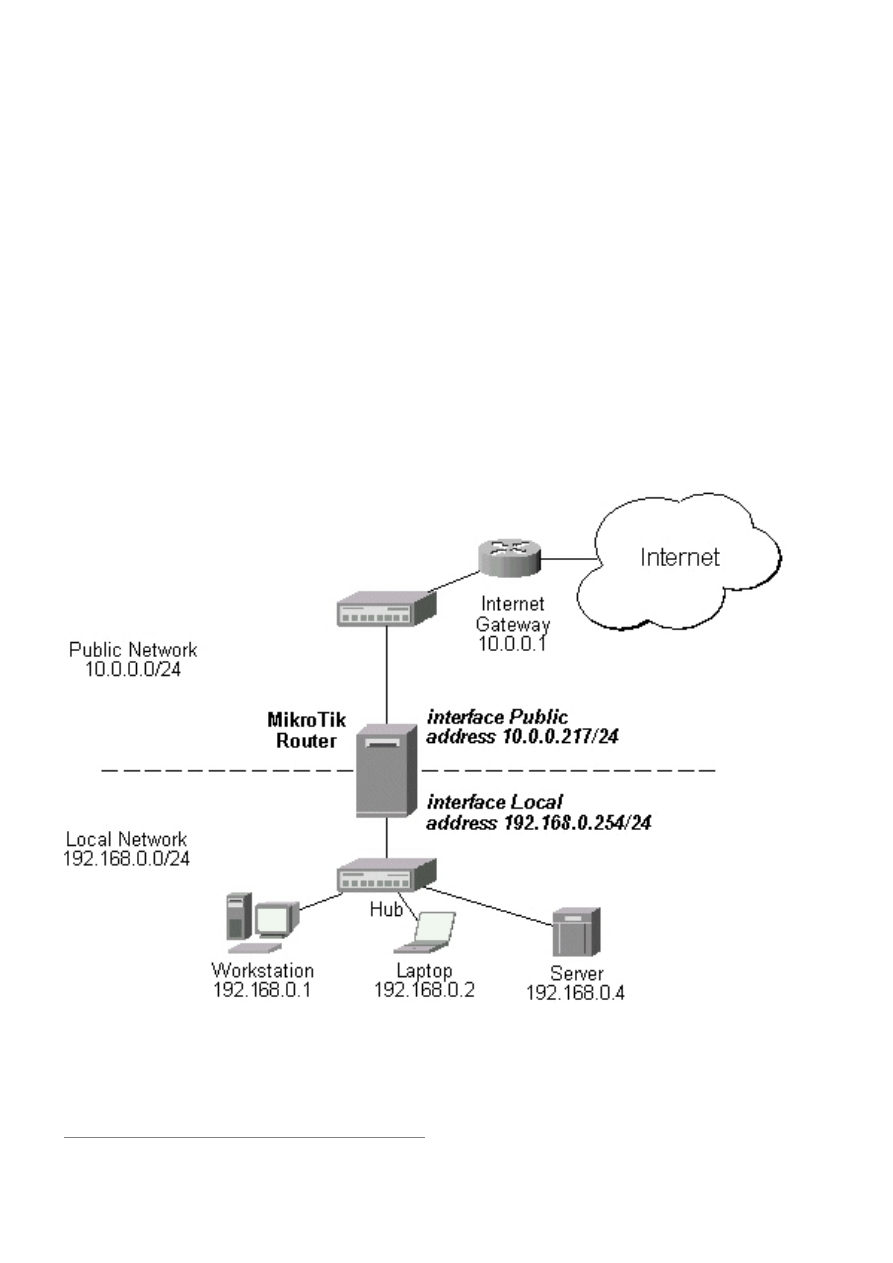
Example of Destination NAT
Assume you need to configure the MikroTik router for the following network setup, where the
server is located in the private network area:
The server has address 192.168.0.4, and we are running web server on it that listens to the TCP port
80. We want to make it accessible from the Internet at address:port 10.0.0.217:80. This can be done
by means of destination Network Address Translation (NAT) at the MikroTik Router. The Public
address:port 10.0.0.217:80 will be translated to the Local address:port 192.168.0.4:80. One
destination NAT rule is required for translating the destination address and port:
Page 12 of 13

/ip firewall dst-nat add action=nat protocol=tcp \
dst-address=10.0.0.217/32:80 to-dst-address=192.168.0.4
Page 13 of 13
Document Outline
- Table of Contents
- General Information
- Packet Flow
- Firewall Rules
- Firewall Chains
- IP Firewall Applications
Wyszukiwarka
Podobne podstrony:
PANsound manual
als manual RZ5IUSXZX237ENPGWFIN Nieznany
hplj 5p 6p service manual vhnlwmi5rxab6ao6bivsrdhllvztpnnomgxi2ma vhnlwmi5rxab6ao6bivsrdhllvztpnnomg
BSAVA Manual of Rabbit Surgery Dentistry and Imaging
Okidata Okipage 14e Parts Manual
Bmw 01 94 Business Mid Radio Owners Manual
Manual Acer TravelMate 2430 US EN
manual mechanika 2 2 id 279133 Nieznany
4 Steyr Operation and Maintenance Manual 8th edition Feb 08
Oberheim Prommer Service Manual
cas test platform user manual
O'Reilly How To Build A FreeBSD STABLE Firewall With IPFILTER From The O'Reilly Anthology
Kyocera FS 1010 Parts Manual
juki DDL 5550 DDL 8500 DDL 8700 manual
Forex Online Manual For Successful Trading
ManualHandlingStandingAssessment
Brother PT 2450 Parts Manual
więcej podobnych podstron