
NOTICE
This equipment has been tested and found comply with the limits for
a Class A digital device, pursuant to part 15 of the FCC Rules.
These limits are designed to provide reasonable protection against
harmful interface when the equipment is operated in a commercial
environment. This equipment generates, uses, and can radiate
radio frequency energy and, if not installed and used in accordance
with the instruction manual, may cause harmful interface to radio
communications. Operation of this equipment in a residential area is
likely to cause harmful interface in which case the user will be
required to correct the interface at his own expense.
*
All brand and trademark are belonged to their respective owner.
*
Specifications are subject change without notice.
This device complies with part 15 of the FCC
Rules. Operation is subject to the following two
condition: (1) This device may not cause
harmful interface, and (2) This device must
accept any interface received, including
Interface that may cause undesired operation.
1

Operation Manual
2

Index
1 Instroduction
«««««««««««««««««««««««««««««««««««««««««««««««« 4
Installation
«««««««««««««««««««««««««««««««««««
4
Recommended Steps
««««««««««««««««««««
4
Configuration Flowchart
«««««««««««««««««
5
String Output Flowchart
««««««««««««««««««
5
Default Setting
«««««««««««««««««««««««««««««
6
Manual Label Layout
«««««««««««««««««««««
7
Frequent Question
««««««««««««««««««««««««
8
2 Interface
««««««««««««««««««««««««««««««««««««««««««««««««««««««« 10
Host Interface
««««««««««««««««««««««««««««««
10
Keyboard Wedge
««««««««««««««««««««««««««
11
RS-232C
«««««««««««««««««««««««««««««««««««««
15
Wand Emulation (Linker or Pen)
«««««««
18
OCIA
«««««««««««««««««««««««««««««««««««««««««
20
3 System Control
««««««««««««««««««««««««««««««««««««««««««««« 21
4 Code Option
««««««««««««««««««««««««««««««««««««««««««««««««« 26
UPC-A
««««««««««««««««««««««««««««««««««««««««
26
UPC-E
««««««««««««««««««««««««««««««««««««««««
28
EAN-13 (ISBN/ISSN)
««««««««««««««««««««
30
EAN-8
««««««««««««««««««««««««««««««««««««««««
32
CODE-39 (CODE-32)
«««««««««««««««««««
34
Interleaved 2 of 5 (Odd S-code)
««««««
36
Industrial 2 of 5
«««««««««««««««««««««««««««««
38
Matrix 2 of 5
««««««««««««««««««««««««««««««««
40
China Post 2 of 5
««««««««««««««««««««««««««
42
Codabar/NW7
««««««««««««««««««««««««««««««
44
Code-128
«««««««««««««««««««««««««««««««««««
46
Code-93
«««««««««««««««««««««««««««««««««««««
48
Code-11
«««««««««««««««««««««««««««««««««««««
50
MSI/Plessey
««««««««««««««««««««««««««««««««
52
UK/Plessey
«««««««««««««««««««««««««««««««««
54
Telepen
««««««««««««««««««««««««««««««««««««««
56
IATA
««««««««««««««««««««««««««««««««««««««««««
58
5 String Format
««««««««««««««««««««««««««««««««««««««««««««««««60
Preamble/Postamble
«««««««««««««««««««««
60
Prefix/Suffix
«««««««««««««««««««««««««««««««««
61
Character Insertion
««««««««««««««««««««««««
62
Other Control
«««««««««««««««««««««««««««««««
64
6 Cable Type
««««««««««««««««««««««««««««««««««««««««««««««««««««66
7 Test Chart
««««««««««««««««««««««««««««««««««««««««««««««««««««« 68
8 ASCII Code/Hexdecimal Table
«««««««««««««««««««««««71
3

Installation
1) First of all, you must make sure that the power is disconnected
form your equipment before connecting the scanner. Beside, you
also have to check the cable connector of the scanner match
your equipment interface correctly.
2) Boot up your computer after connecting the scanner with your
equipment, the scanner will make a long music and light the LED,
above scanner to indicate a successful power on. Trigger the
button, the scan line in front of scanner will active. Now you can
start to set programming optimal usage.
*
If any of the above operation is not right, turn off the power
immediately and check any improper connections. Go through all
above steps again.
Recommened Steps
When the required settings have been configured, all settings
are stored in non volatile memory of scanner after reading
E XIT
label. There are recommended steps as follows.
1) Set right host interface for your scanner at
/10.
(The scanner is in factory default as bold label)
2) Set interface to optimize protocol of scanner with your host in
Charter 2.
3) Set system control of scanner, such as specific adjustments
double confirm, power saving, indicator and scanning mode
which you prefer usage in Chapter 3.
4) Set code option of scanner for your usage in Chapter 4. You must
make sure to enable the symbology first, then Min./Max. code
length, code ID checksum and truncate digits are also convered.
5) Set string format of the scanner, such as preamble, postamble,
prefix, suffix, code ID and code name transmission for your
application in Chapter 5.
*
If any of the error step is processing, scanner will generate a 5
wanrrying beeps to indicate an invaild setting. You have to take care
this matter and set correctly again.
*
If still not work properly. Please contact with dealer.
Operation Manual
4
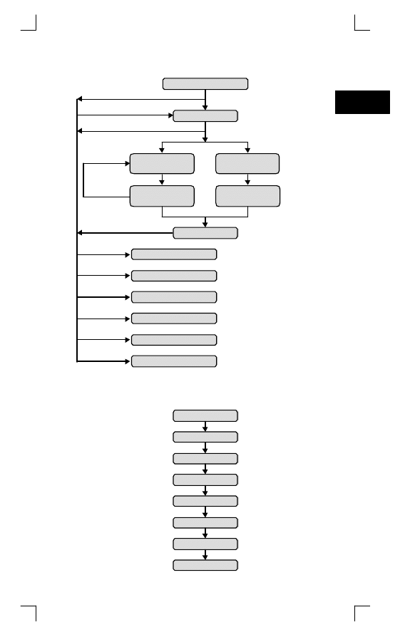
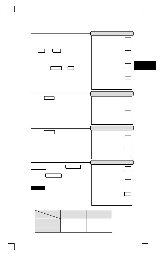
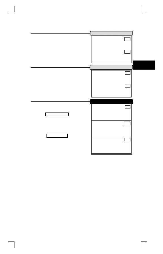
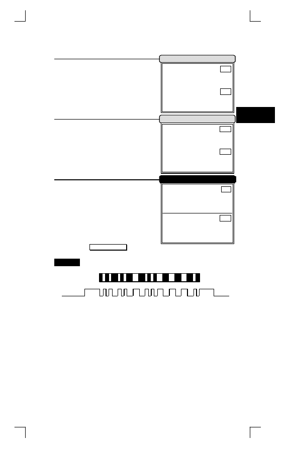
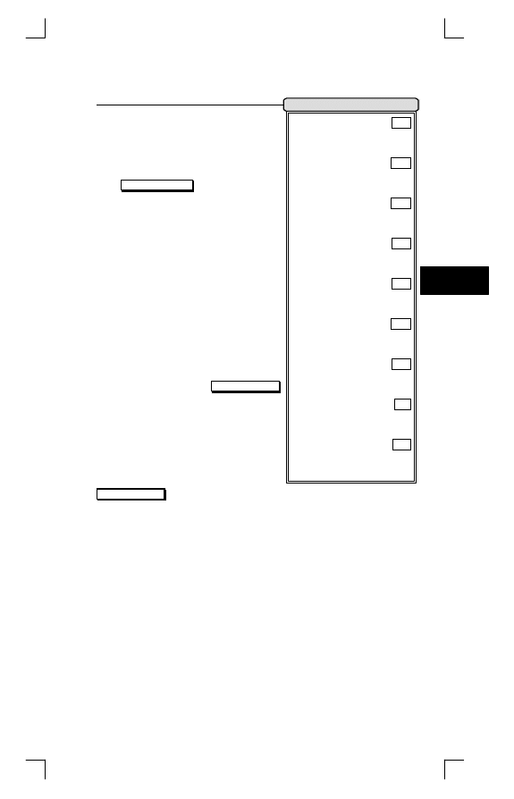
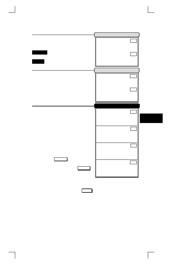
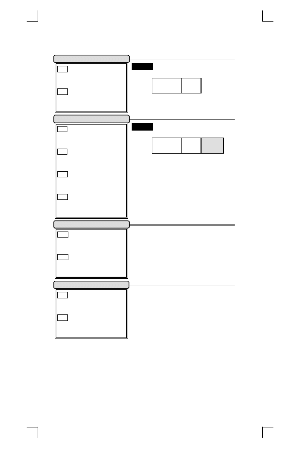
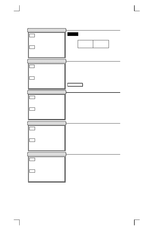
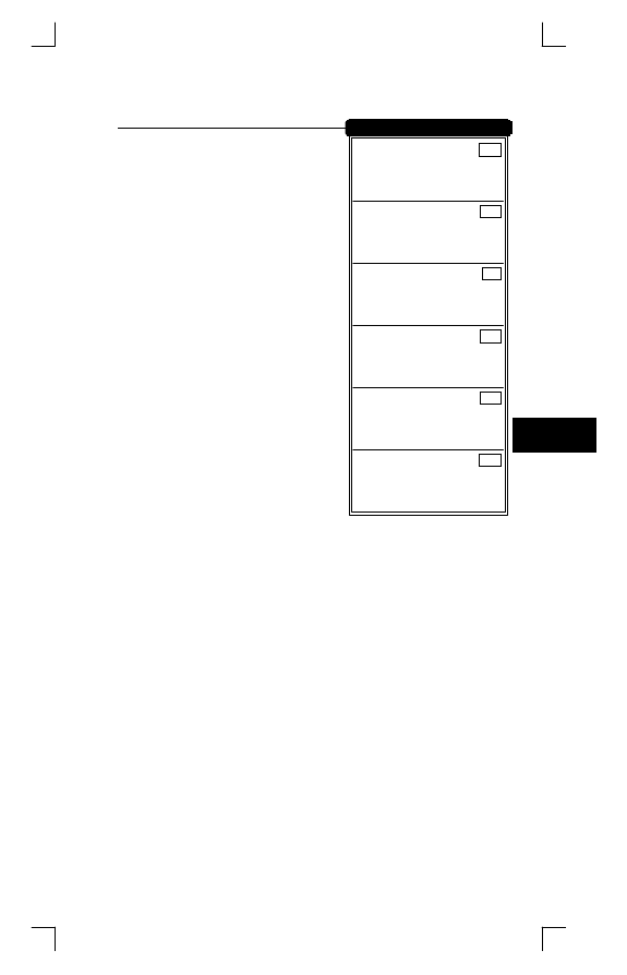
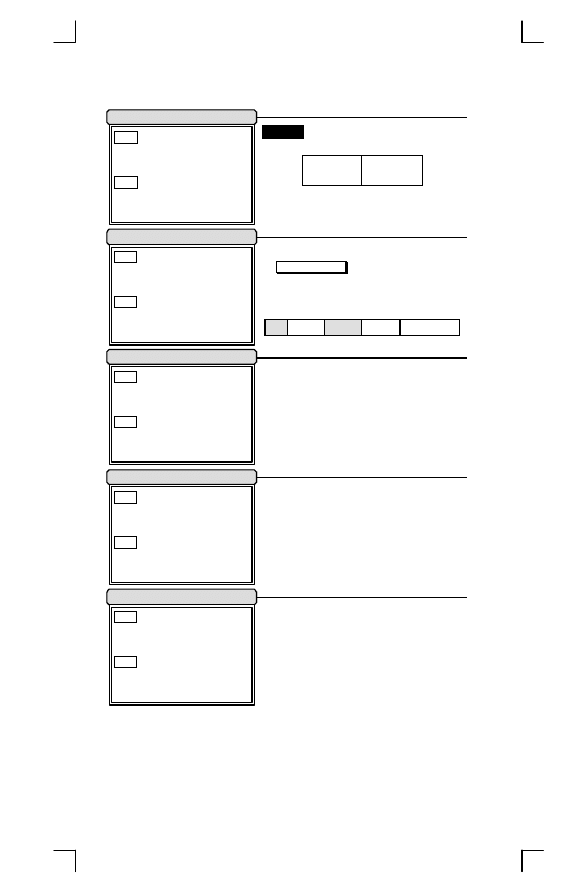
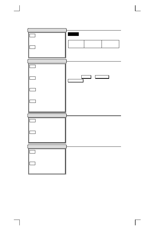
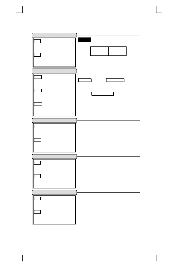
Configuration Flowchart
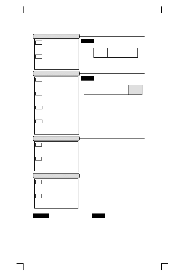
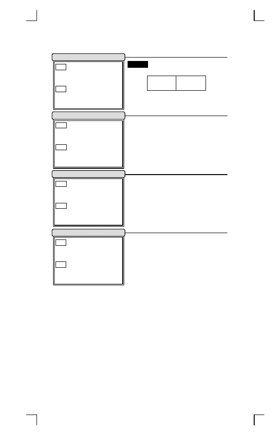
String Output Flowchart
Preamble
Prefix
Code Name
Code ID
Code Data
Code Length
Suffix
Postamble
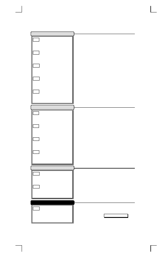
Enter
Programming
Mode
Finish ASCII
Code or Decimal
Value Setting
Select Function
Label
Interface Default
Exit & Interface Default
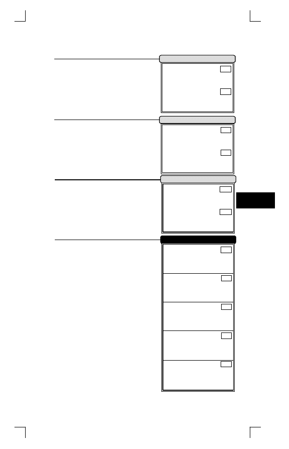
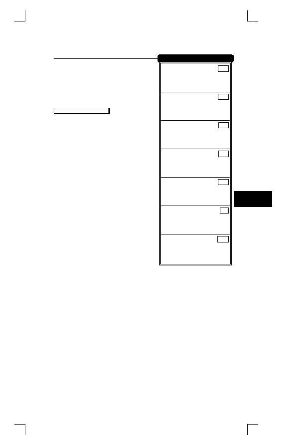
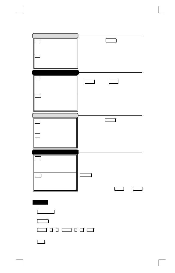
Function
PROGRAM
Decimal
(10's Value)
Hexdecimal
(High Byte)
Decimal
(1's Value)
Hexdecimal
(Low Byte)
SET
EXIT
ABORT
VERSION DATE
SETTING LIST
DEFAULT
Prefix or
Suffix
Only
Set ASCII Code
Set Decimal Value
Exit With Save
Exit Without Save
Exit & Default
Exit & Version List
Exit & Setting List
5
Introduction
1

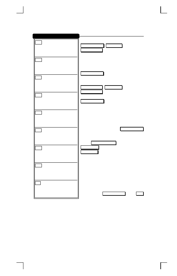
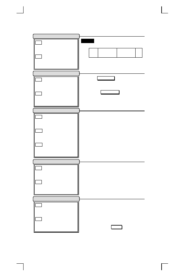
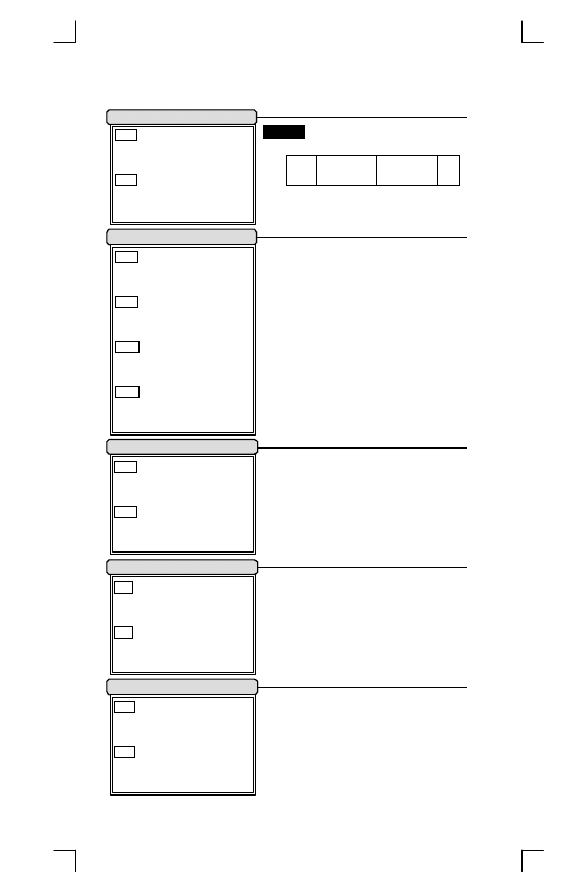
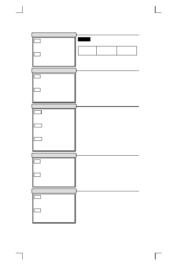
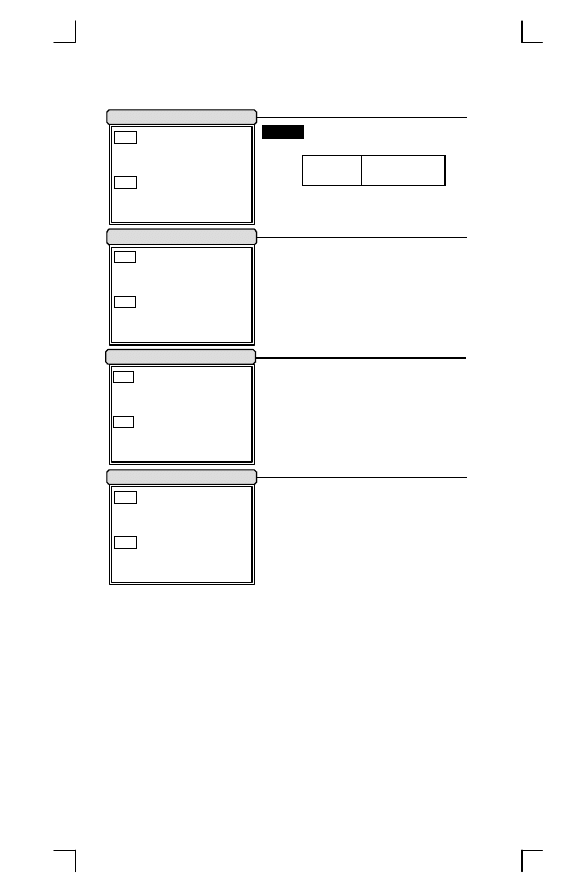
Default Setting
Length
Truncate
Code
Type
Read
Enable Min. Max. Leading Ending
Code
ID
UPC-A
3
-
-
0
0
A
UPC-E
3
-
-
0
0
E
EAN-13
3
-
-
0
0
F
EAN-8
3
-
-
0
0
FF
Code-39
3
0
0
0
0
M
Interleaved 2 of 5
6
0
0
0
I
Industrial 2 of 5
4
0
0
0
H
Matrix 2 of 5
4
0
0
0
G
China Post 2 of 5
11
11
0
0
J
Codabar/NW7
3
4
0
0
0
N
Code-128
3
0
0
0
0
K
Code-93
4
0
0
0
L
Code-11
4
0
0
0
O
MSI/Plessey
4
0
0
0
P
UK/Plessey
4
0
0
0
R
Telepen
4
0
0
0
S
IATA
4
0
0
0
Q
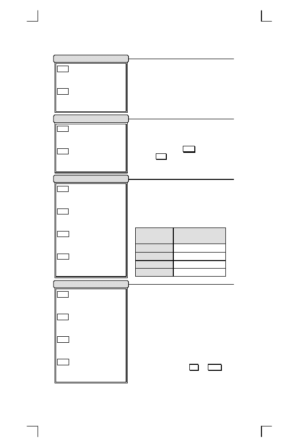
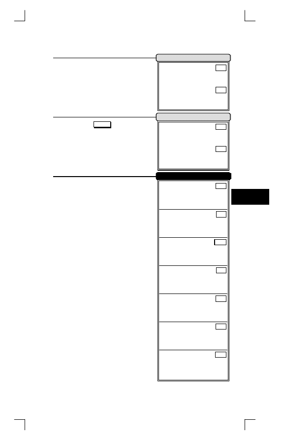
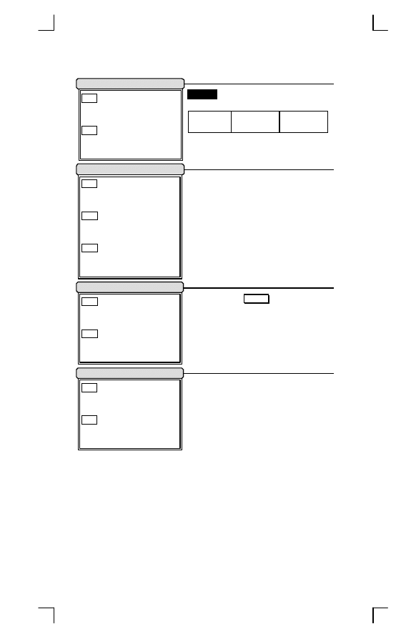
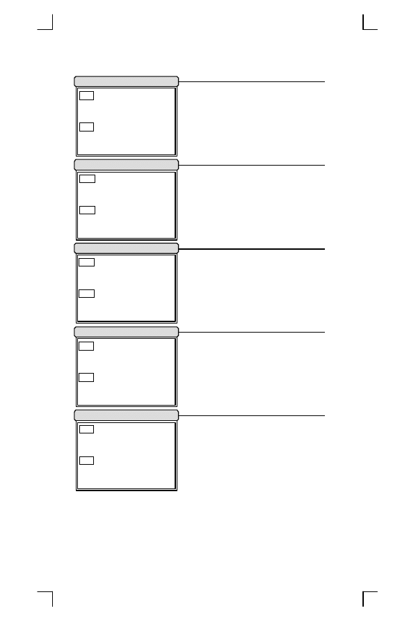
Adjustment
Value
Result
Beep Loudness
05
Level 5
Beep Tone
24
2.4 KHz
Beep Duration
06
60 mSec
Beep Tone1
12
1.2 KHz
Beep Duration1
06
60 mSec
Stand-by Time
15
15 Sec
Active Time
20
200 mSec
Sleep Time
20
200 mSec
Good-read Delay
50
500 mSec
Double Confirm Times
01
Once
Inter-char. Delay
01
1 mSec
Transmit Delay
00
0 mSec
Response Delay
30
3 Sec
Add-on Wait Time
50
500 mSec
Margin Delay
10
100 mSec
Preamble Data1
00
16
<NULL>
Preamble Data2
00
16
<NULL>
Postamble Data1
0D
16
<CR>
Postamble Data2
0A
16
<LF>
Prefix Data (All Datas)
00
16
<NULL>
Suffix Data (All Datas)
00
16
<NULL>
Add-on Insertion (All Datas)
00
16
<NULL>
Insertion1-4 (Position & All Datas)
00
16
<NULL>
Concatenation Data
29
16
<GS>
Operation Manual
6
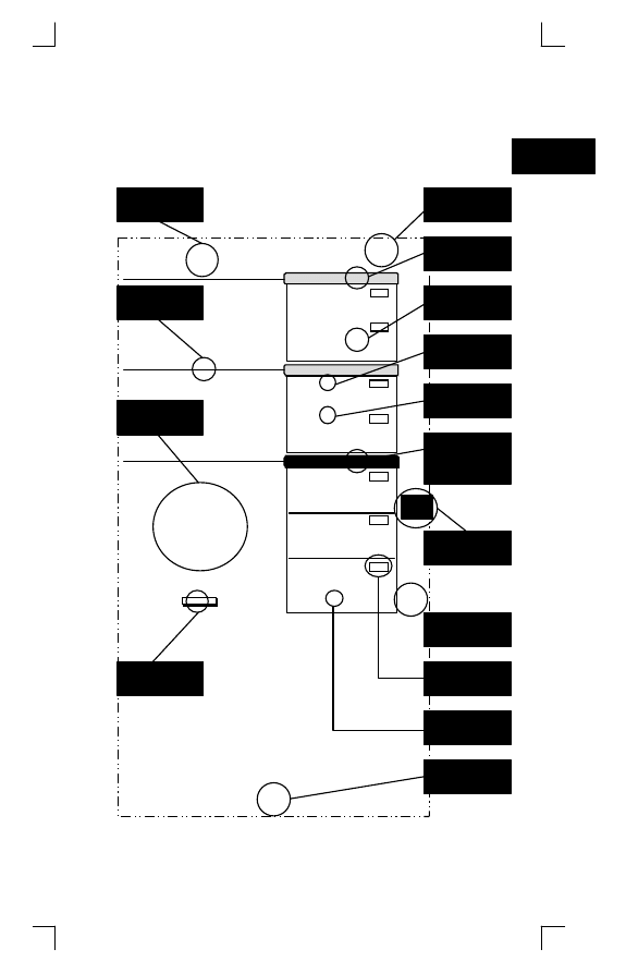
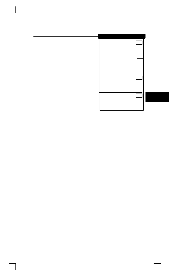
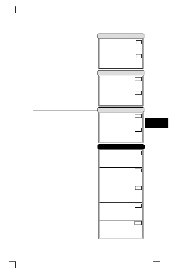
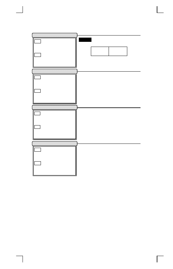
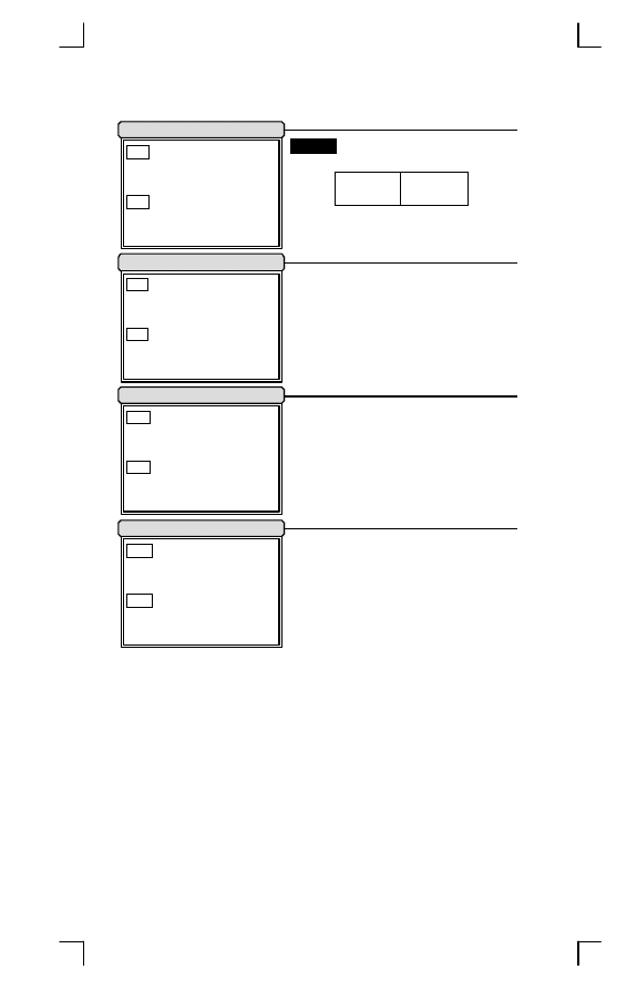
Manual Label Layout
The scanner must be set by reading the barcode labels in
manual. The discription of label is as follows.
*
The factory default settings are indicated by bold symbols.
Disable
DZA
*DZA*
Enable
DZB
*DZB*
Spare Function
Disable
DYA
*DYA*
Enable
DYB
*DYB*
Truncate
Leading BAO
*BAO*
(Range:00
1 0
-15
1 0
)
Truncate
Ending BAP
*BAP*
(Range:00
1 0
-15
1 0
)
Code ID
AAA
*AAA*
(Range:00
1 6
-FF
1 6
ASCII Code)
Specific Adjustments
Truncate Leading Zero
EXIT
UPC-A
*/$%END*
Code Option
4
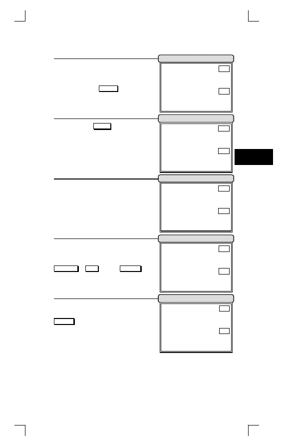
Truncate Leading / Ending: The
leading or ending digits of barcode
data characters can be truncated
when these values are set to non
zero. It will be read nothing else only
beeps when the truncate value is
more than barcode data digits or the
value of Truncate Leading is overlap
with the Ending. The maximum value
of Truncate digits is 15.
Code ID: A C ode ID is a character
27
Section
Title
Exit
Program
Command
For RS-232C
Selection
Label
Default
Setting
Selection
Description
Chapter
Number
Chapter
Title
Page
Number
Function
Title
Adjustment
(ASCII Code or
Decimal Value)
Group
Line
Selection
Label
Range
Description
Function
Description
7
Introduction
1

Frequent Question
Q: Why scanner block the keyboard operation?
A: Check the cable connection with your equipment, then turn power
on again.
Q: If scanner has a good read beep but nothing transferring
after read a label.
A: Using the
S ETTING LIST
at
/10 to show what current setting of
scanner is, or reset to Default, (or select right Interface default if
scanner to be change another interface used), then re-program
scanner again.
Q: If scanner dosen't need an Enter character addition after
each barcode label transmission.
A: Refer to postamble transmission at
/60, then set
D isable
.
Q: If scanner needs to read single digit code.
A: Refer to Min. code length of code option use "01" in Chapter 4 for
single code readable.
Q: If scanner isn't able to discriminate an unknown label, but
read manual very well.
A: Refer to code name at
/64 to set
E nable
, read a barcode label,
then you will know what symbology is read. Beside, it maybe
need to verify checksum. Refer to verify checksum of code option
in Chapter 4, and set
E nable
.
Q: If scanner transfers character very slow or loses some
characters on screen in keyboard interface after reading a
label.
A: You may set caps lock to be
A lt+Keypad
at
/11. Otherwise, it
maybe mis-match of transmission rate, therefore, you can adjust
an appropriate
I nter-char. Delay
to match your equipment. See
/11.
Q: If scanner want to read a label as function key for your
apprication.
A: Refer to function key simulation at
/11 and set
E nable
, then
scanner can transmit a code as function key. It is used for
keyboard interface only. Beside, you must make sure that a label
is encoded as function key, and its ASCII code is from 00
16
to
1F
16
You can refer to ASCII code table at
/71.
Operation Manual
8
Q:Could I change scanner into different type interface directly?
A: You can change factory interface default for other type interface.
By plug different cable, program scanner and set right interface to
exit, then the scanner will be change to another interface.
However, you must make sure what cable you need. Refer Cable
Type to
/66, 67.
Q: How to configure scanner via RS-232C?
A: Next to the selection description, you will find a frame command,
such as AAB. These commands can be sent to scanner with
RS-232C interface. You must make sure that scanner is the same
protocal as your equipment of RS-232C, and light source of
scanner has been actived by pressing button.
Example
Beep Loudness Level "10", Good-read Beep "Enable"
To configure the reguired commands proceed as follows:
Send as:
<ESC>(1B
16
)
ï Command(s) ï <CR>(0D
16
)
Send
<ESC>
ï BACï %01ï %00ï %OKï CEBï <CR>
Beep
1
0
SET Good-read
Londness Level
Beep Enable
*
Call to the dealer if scanner dose not work properly.
9
Introduction
1
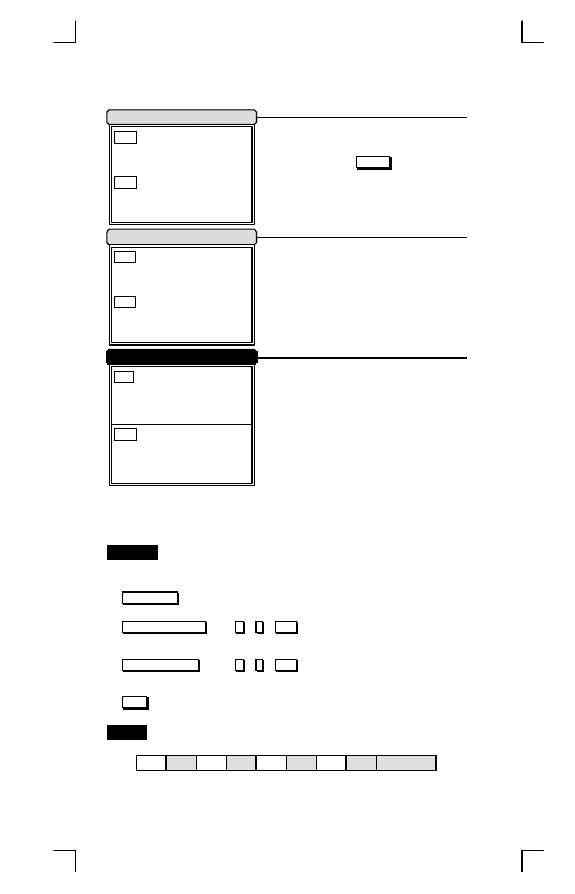
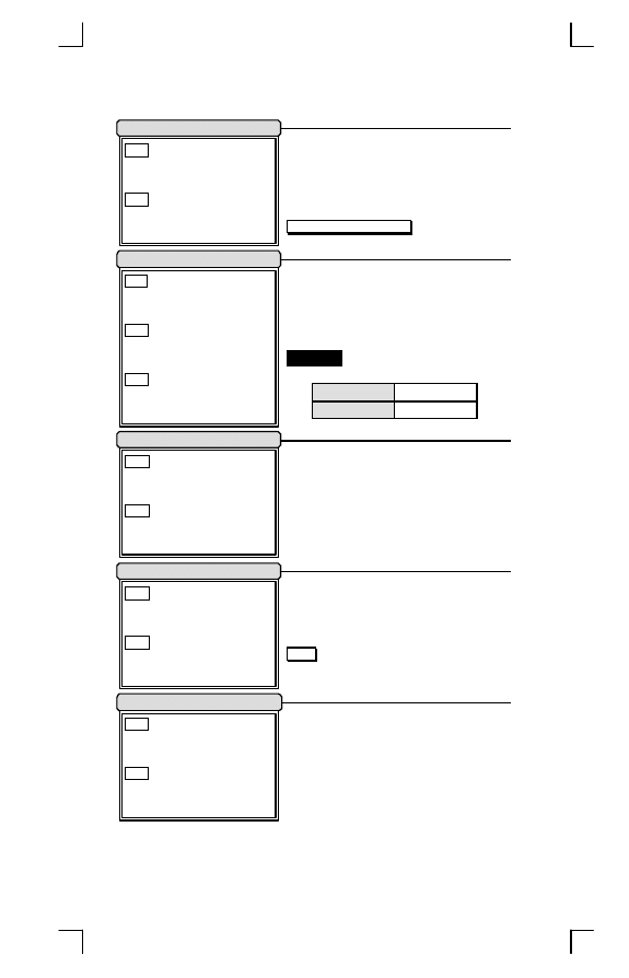
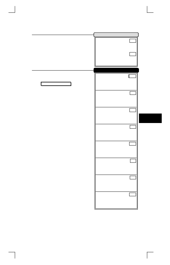
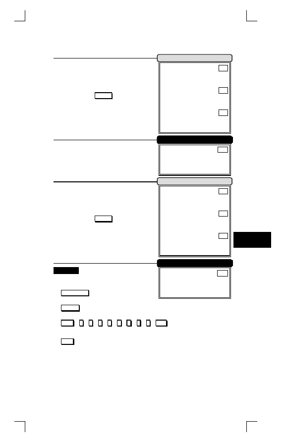
You can change factory
interface default for other type
interface. By plug different
cable, program scanner and
set right interface to exit, then
the scanner will be change to
another interface. However,
you must make sure what
cable you need. Refer Cable
Type to
/66, 67.
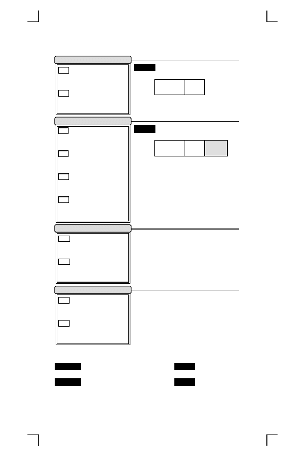
DEFAULT: All settings are
reset as bold label, but
exclude interface setting.
VERSION DATE: You can get
the software date of decoder
on screen. It is important for
maintanace.
SETTING LIST: First it is
recommended that you need
to excute a text editor
program (such as PE2 and
Word) for keyboard interface,
or excute a terminal program
(such as Hyper Terminal) for RS-232. Then scanner will transmit
current settings on screen.
ABORT: If you have a mis-setting or want to skip this current
configuration during you are programming, using this function, all
front settings are aborted before you set
E XIT
to finish
programming.
*
Programming will be finished while each label of miscellany is
read.
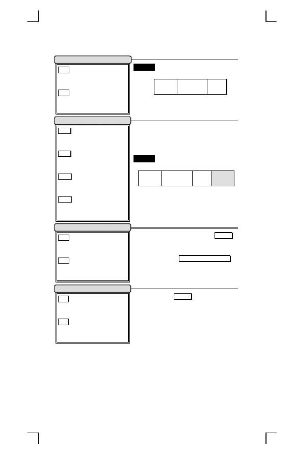
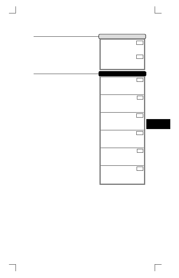
Keyboard Wedge
*/$%C00*
RS-232C
*/$%C01*
WAND EMULATION
*/$%C02*
OCIA
*/$%C03*
Spare Interface
*/$%C04*
Interface Default
DEFAULT (without Interface)
*/$%DEF*
VERSION DATE
*/$%VER*
SETTING LIST
*/$%LST*
ABORT
*/$%ESC*
Miscellany
PROGRAM
*/$%STR*
Host Interface
Operation Manual
10
Low
CZA
*CZA*
Medium
CZB
*CZB*
High
CZC
*CZC*
Turbo
CZD
*CZD*
Numeric Key Position
Caps Lock
Keyboard Speed
Function Key Simulation
By selecting, you can change
output speed of scanner to advance or
match with host computer. Generally,
set
H igh
or
Turbo
in working high
performance. If some output
characters of barcode have been lost
or shown on screen slowly, you may
need to set
Medium
or
L ow
to match
your host keyboard speed.
Set
E nable
scanner can output
code as pressing function-key in your
application program while the barcode
datas contain ASCII value between
01
16
to 1F
16.
. See
/60 and Refer to
ASCII table
/71 at grey area. You'll
find function-keys with ASCII codes.
The
K eypad
have to selecte if your
application program is only keypad
numeric code acceptable. So, scanner
will output code as press numeric key-
pad when it read numeric digit. (The
keypad is in the right side of keyboard,
and Num Lock control key is also on.)
By selecting
U ppercase
or
L owercase
, scanner can get Caps Lock
status. If
A lt+Keypad
is selected, Caps
Lock and output will be independent.
Example
Barcode "ABCdef"
Status
Selection
Caps Lock
On
Caps Lock
Off
Uppercase
ABCdef
abcDEF
Lowercase
abcDEF
ABCdef
Alt+Keypad
ABCdef
ABCdef
Alphabetic-key
DAA
*DAA*
Keypad
DAB
*DAB*
Uppercase
DDA
*DDA*
Lowercase
DDB
*DDB*
Alt+Keypad
DDD
*DDD*
Disable
DBA
*DBA*
Enable
DBB
*DBB*
EXIT
Keyboard Wedge
*/$%END*
11
Interface
2
Specific Adjustments
BAL
Inter-char. Delay
*BAL*
(Range:00
10
-99
10
Unit:1ms)
BAM
Transmit Delay
*BAM*
(Range:00
10
-99
10
Unit:10ms)
Keyboard Simulation
Spare Function
All of the PCs check the keyboard
status during power-on selftest. It is
recommended to
E nable
the function if
you are working without keyboard
installation. It simulates keyboard
timing and pass keyboard present
status to the PC during power-on.
Inter-char. Delay: This delay is
inserted after each data characters
transmitted.If the transission speed is
too high, the system may not be able
to receive all characters. Adjust it and
try out suited delay to makes system
work properly.
Transmit Delay: It is a delay timer between barcode data output.
The feature is used to transfer continually with shorter barcode data
or multi-field scanning.
Example
Barcode Data: "ABCD"
Inter-char. Delay: 2ms
Transmit Delay: 10ms
1)
P ROGRAM
ï
Entry Programming
2)
Inter-char. Delay
ï
0
ï
2
ï
S ET
ï
2ms Inter-char. Delay
02*1ms(Unit)=2ms
3)
Transmit Delay
ï
0
ï
1
ï
S ET
ï
10ms Transmit Delay
01*10ms(Unit)=10ms
4)
E XIT
Exit Programming
Output
A
2ms
B
2ms
C
2ms
D 2ms
10ms
DEA
Disable
*DEA*
DEB
Enable
*DEB*
DCA
Disable
*DCA*
DCB
Enable
*DCB*
PROGRAM
*/$%STR*
Keyboard Wedge
Operation Manual
12
Select keyboard type connector of
your host computer. Scanner must be
selected to the appropriate host
interface cable converter. Refer to
Cable Type at
/66.
IBM AT,PS/2
DFA
*DFA*
IBM XT
DFB
*DFB*
Macintosh ADB.
DFC
*DFC*
IBM PS/2 25,30
DFD
*DFD*
NEC 9801
DFE
*DFE*
IBM PS/2 55
DFF
*DFF*
IBM 5550
DFG
*DFG*
KT 106
DFH
*DFH*
IBM 5576
DFI
*DFI*
Spare1
DFJ
*DFJ*
Spare2
DFK
*DFK*
Spare3
DFL
*DFL*
Spare4
DFM
*DFM*
Keyboard Type
EXIT
Keyboard Wedge
*/$%END*
13
Interface
2
Keyboard Layout
The selecting of keyboard layout
supports many country languages
other than USA keyboard layout. First
you need to confirm country langage
that you desire. In DOS, using
command "Keyb" to selecte the
desirable keyboard layout or in
WINDOWS entry "Control' then pop
"Keyboard" to selecte country at
"language" item. For details, please
refer to your DOS or WINDOWS
user's manual.
DGA
USA (US)
*DGA*
DGB
Belgium (BE)
*DGB*
DGC
Danish (DK)
*DGC*
DGD
France(FR)
*DGD*
DGE
Germany (GR)
*DGE*
DGF
Italian (IT)
*DGF*
DGG
Portuguese (PO)
*DGG*
DGH
Spanish (SP)
*DGH*
DGI
Swedish (SV)
*DGI*
DGJ
Switzerland (SF)
*DGJ*
DGK
UK (UK)
*DGK*
DGL
Latin American (LA)
*DGL*
DGM
Japan
*DGM*
DGN
Spare2
*DGN*
PROGRAM
*/$%STR*
Keyboard Wedge
Operation Manual
14
Handshaking Protocol
CTS: Clear To Send
(Hardware Signal)
RTS: Request To Send (Hardware Signal)
STX: Start Of Text
(ASCII Code 02
16
)
ETX: End Of Text
(ASCII Code 03
16
)
Xon: Transmit On
(ASCII Code 13
16
)
Xoff: Transmit Off
(ASCII Code 11
16
)
Disable: The communication only
uses TxD and RxD signals without
regard for any hardware or software
handshaking protocol.
RTS/CTS (CTS/RTS): If the scanner
wants to send the barcode data to host
computer, it will issue the RTS (CTS)
signal first, wait for the CTS (RTS)
signal from the host computer, and
then perform the normal data
communication. If there is no replied
CTS (RTS) signal from the host
computer after the timeout (Response
Delay) duration, the scanner will issue
a 5 warning beeps.
Scanner Ready: The scanner will
active the RTS signal after power-on,
and will transmit data upon receiving
active CTS signals.
Data Ready: The scanner will active the RTS signal to indicate a
successful decoding and will transmit data upon receiving CTS
signals.
STX/ETX: The STX and ETX are used to pack barcode together in
the normal data transmission.
Xon/Xoff: When the host computer is unable to accept data, it
sends an Xoff code to inform the scanner to suspend data
transmission,and Xon to continue.
CTS Trigger: This operation enabled an external device to control
scanning. The CTS trigger is controlled by applying an external
trigger signal to the CTS input. When active, this signal causes
scanning to begin as if the scanner's trigger was depressed. In the
event of decoding, the trigger signal must be deactivated for a
minimum of 50ms before another scan can be attempted.
Disable
DLA
*DLA*
RTS/CTS
DLB
*DLB*
CTS/RTS
DLC
*DLC*
Scanner Ready
DLD
*DLD*
Data Ready
DLE
*DLE*
Xon/Xoff
DLF
*DLF*
STX/ETX
DLG
*DLG*
CTS Trigger
DLH
*DLH*
Spare
DLI
*DLI*
EXIT
RS-232C
*/$%END*
15
Interface
2
Data Parity
Baud Rate
DHA
38400 Bps
*DHA*
DHB
19200 Bps
*DHB*
DHC
9600 Bps
*DHC*
DHD
4800 Bps
*DHD*
DHE
2400 Bps
*DHE*
DHF
1200 Bps
*DHF*
DHG
600 Bps
*DHG*
DHH
300 Bps
*DHH*
DKA
None
*DKA*
DKC
Even
*DKC*
DKD
Odd
*DKD*
DKE
Space
*DKE*
DKF
Mark
*DKF*
PROGRAM
*/$%STR*
RS-232C
Operation Manual
16
Inter-char. Delay: It is delay time
between data character's output. It is
same as
I nter-char. Delay
of keyboard
wedge, see
/12.
Transmit Delay: It is a delay time
between barcode data output. It is also
same as
Transmit Delay
of Keyboard
wedge, see
/12.
Response Delay: This delay is used
for serial communication of the
scanner to waiting for handshaking acknowledgment from the host
computer. If scanner doesn't get any acknowledgments form host
after the timeout occurs, it will issue 5 warning beeps.You may
check handshanking mode or adjust a longer delay timer. The
feature is particularly useful for some applications that the host
computer takes a longer time to respond.
Specific Adjustments
Inter-char. Delay
BAL
*BAL*
(Range:00
10
-99
10
Unit:1ms)
Transmit Delay
BAM
*BAM*
(Range:00
10
-99
10
Unit:10ms)
Response Delay
BAN
*BAN*
(Range:01
10
-99
10
Unit:100ms)
Stop Bits
One Bit
DIA
*DIA*
Two Bits
DIB
*DIB*
Data Bits
7 Bits
DJA
*DJA*
8 Bits
DJB
*DJB*
EXIT
RS-232C
*/$%END*
17
Interface
2
Active Level
Normal Level
Narrow/Wide Ratio
Output Speed
DOA
Low
*DOA*
DOB
Medium
*DOB*
DOC
High
*DOC*
DOD
Turbo
*DOD*
Bar Hi/Space Lo: Black will be
transmited as a high voltage level
(+5V) and space as low level (0V).
Bar Lo/Space Hi: Black will be
transmited as a low voltage level (0V)
and space as high level (+5V).
You must make sure what is
Normal Level of your wand decoder
device in stand-by (idle). So, initial
signal state as a
H igh
voltage level
(+5V) or
L ow
voltage level (0V).
This setting is same as serial
transmission baud rate, and it must be
approbated your wand decoder
resolution. The unit of speed is a width
of minimum narrow bar.
Output
Speed
Bps
(bits per second)
Low
1200
Medium
2400
High
4800
Turbo
9600
The setting is applied two kinds of
ratio barcode symbologies with narrow
and wide only, such as Code-39,
Interleaved 2 of 5, Codabar, Plessey
and IATA...etc. So, it will be ignored if
some kinds of barcode symbologies,
such as EAN, UPC, and Code-128,
are read. This setting is able to adjust
appropriate signal width during
transmitting the bar image. The ratio
allows to adjust from
1 :2
to
1 :3.5
, but
upon your wand decoder device.
DMA
Bar Hi/Space Lo
*DMA*
DMB
Bar
Lo/
Space
Hi
*DMB*
DNA
Low
*DNA*
DNB
High
*DNB*
DQA
1:2
*DQA*
DQB
1:2.5
*DQB*
DQC
1:3
*DQC*
DQD
1:3.5
*DQD*
PROGRAM
*/$%STR*
Wand Emulation
Operation Manual
18
Discrete codes such as Code-39
and Codabar are featured an Inter-
Char. Gap between two characters of
barcode. It makes them suitable for
printing in the Narrow or Wide gap by
mechanical numbering system. You
can choice one suit your decoder.
Generally, wand emulation Output
signals same as symbology when it
read a barcode. By setting, the
scanner can read many kinds of
barcode symbologies, but transmitted
as code-39 full ASCII format, even
your decoder device no support them.
Margin Delay: It is a timer of zone like
space zone of barcode label margin.
The width of margin time will be added
before and after in each barcode data
automatically when it is transmitted.
Transmit Delay: It is a delay time
between barcode data output. It is
the same as
Transmit Delay
of keyboard wedge, see
/12.
Example
Normal Level: Low, Bar Lo/Space Hi
Barcode Pattern
… … 5v
Normal Low
0v
Margin Delay
Margin Delay
Inter-char. Gap
Narrow
DPA
*DPA*
Wide
DPB
*DPB*
Code-39 Simulation
Disable
DRA
*DRA*
Enable
DRB
*DRB*
Specific Adjustments
Margin Delay
BAL
*BAL*
(Range:00
10
-99
10
Unit:10ms)
Transmit Delay
BAM
*BAM*
(Range:00
10
-99
10
Unit:10ms)
EXIT
Wand Emulation
*/$%END*
19
Interface
2
Protocol Type
Data Parity
Specific Adjustments
Spare Function
Tansmit Delay: It is a delay time
between barcode data output. It is also
the same as
Transmit Delay
of
keyboard wedge, see
/12.
DSA
NCR
*DSA*
DSB
DTS
*DSB*
DSC
NCR+ASCII
*DSC*
DSD
DTS+ASCII
*DSD*
DSE
ASCII
*DSE*
DTA
Even
*DTA*
DTB
Odd
*DTB*
DTC
Space
*DTC*
DTD
Mark
*DTD*
DUA
Disable
*DUA*
DUB
Enable
*DUB*
BAM
Transmit Delay
*BAM*
(Range:00
10
-99
10
Unit:10ms)
PROGRAM
*/$%STR*
OCIA
Operation Manual
20
After power-on the scanner will
generate music to indicate the
successful selftest. You can inhibit the
music by setting
D isable
.
By setting
E nable
, the scanner will
activate the light source after the
power-on without trigger button.
After each successful reading, the
scanner will light Good-read LED
above scanner to indicate a good
barcode reading.
After each successful reading, the
scanner will beep buzzer to indicate a
good barcode reading, and its
L oudness
,
Tone
and
D uration
are
adjustable by setting of Specific
Adjustment at
/24.
The scanner will operate in Power
Saving mode as this function is
E nabled
. Current will be reduced to
less than 20 mA, but sensibility is also
become slowly. You will find the light
source of CCD scanner to be flashed
and motor of laser scanner to be
stoppped as it read a code or timeout.
Disable
CBA
*CBA*
Enable
CBA
*CBB*
Power-on Music
Power-on Auto Trigger
Disable
CCA
*CCA*
Enable
CCB
*CCB*
Good-read LED
Disable
CDA
*CDA*
Enable
CDB
*CDB*
Good-read Beep
Disable
CEA
*CEA*
Enable
CEB
*CEB*
Power Saving
Disable
CJA
*CJA*
Enable
CJB
*CJB*
Power Saving
EXIT
System Control
*/$%END*
21
System Control
3
Inter-char. Gap
Double Confirm
Case Conversion
Field Control
Spare Function
The scanner will require many
times of successful decoding to
confirm the barcode data, and the
more confirm times the more inhibitive
mis-reading code. (Refer to setting of
D oubble Confirm Times
at
/25)
It converses all output characters
to be same printing-case, even they
have two kinds of case within a
barcode data.
Example
Barcode "BarCode",
Uppercase
BARCODE
Lowercase
barcode
The scanner can read many sets
of barcode data on the same scanning
line at the same time, even they are
different kinds of barcode symbology.
The direction of read-out is form left to
right. Refer to Codabar/NW7 of Test
Chart at
/69.
Discrete codes such as Code-39
and Codabar are featured with an
Inter-char. Gap between two
characters of barcode.You may set
W ide
as the Inter-char. Gap of barcode
lable is wider.
CGA
Narrow
*CGA*
CGB
Wide
*CGB*
CPA
Disable
*CPA*
CPB
Enable
*CPB*
CTA
Disable
*CTA*
CTC
Uppercase
*CTC*
CTD
Lowercase
*CTD*
CRA
One Field
*CRA*
CRB
Multi Field
*CRB*
CSA
Disable
*CSA*
CSB
Enable
*CSB*
PROGRAM
*/$%STR*
System Control
Operation Manual
22
Scanning Mode
Good-read Off: The trigger button
must be pressed to active scanning.
The light source of scanner stops
scanning when there is a successful
reading or no code is decoded after
the
S tand-by Timer
/24 duration
elapsed. (Laser Model Default)
Momentary: The trigger button acts
as a switch. Press button to active
scanning and release button stop
scanning.
Alternate: The trigger button acts as a
toggle switch. Press button to active or
stop scanning.
Timeout Off: The trigger button must
be pressed to active scanning, and
scanner stops scanning when no code
is decoded after the
Stand-by Timer
/24 duration elapsed.(CCD Model
Default)
Timeout Flash: The trigger button
must be pressed to keep scanning.
The scanner flashes the light source
when no code is decoded after the
S tand-by Timer
/24 duration elapsed. This mode can save the
power resource and extend the operation life of the light source. The
scanner can be waked up when there is a successful reading or
trigger button to be pressed.
Continue: The scanner always keeps reading, and no matter when
trigger button is pressed or duration is elapsed.
Test Only: The scanner always keeps reading continuously and
same label reading is allowed without double confirm. The feature
can test the performance of scanner for reading speed and sensitive.
(Diagnostic mode)
Object Detect: Wake up automaticlly without trigger switch, if an
object in the front of scanner is detected.(Some Laser Model Only)
*
For saving power and longer lift of laser component, all scanning
mode, the laser beam and motor will stop when no code is decoded.
Good-read Off
CAB
*CAB*
Momentry
CAC
*CAC*
Alternate
CAD
*CAD*
Timeout Off
CAE
*CAE*
Timeout Flash
CAF
*CAF*
Continue
CAG
*CAG*
Test Only
CAA
*CAA*
Object Detect
CAI
*CAI*
Spare
CAJ
*CAJ*
EXIT
System Control
*/$%END*
23
System Control
3
Specific Adjustments
Beep Adjustments: You can adjust
B eep Loudness
,
B eep Tone
and
B eep Duration
of good reading upon
your pavorite usage.
Stand-by Time: A timeout duration of
1 to 99 seconds can be adjusted. The
S tand-by Time
that is valid scanning
duration. It is only effective when the
scanning mode of CCD is operated in
G ood-read Off
,
Timeout Off
or
Timeout Flash
mode. Beside, if laser
scanner no code to read during
S tand-by Time
, the laser beam and
motor will be shutdown to saving life
time of laser diode.
Active/Sleep Time: There are two
durations that are used when the
scanner operated in
Timeout Flash
scanning mode. The scanner entries
flash operation when no code is read
until
S tand-by Time
timeout. The
A ction Time
is lighting duration and the
S leep Time
is blanking duration while
light source flashing. The barcode can
also be read during flashing of light
source and then waked up the
scanner automatically.
Good-read Delay: This feature is a
limit duration during the same barcode
data to be read continuously, except
operated in
G ood-read Off
and
Test
mode The timer will be reset when
different barcode data reading.
BAC
Beep Loudness
*BAC*
(Range:01
10
-10
10
Unit:Level)
BAD
Beep Tone
*BAD*
(Range:05
10
-50
10
Unit:100Hz)
BAE
Beep Duration
*BAE*
(Range:01
10
-99
10
Unit:10ms)
BDA
Beep Tone1
*BDA*
(Range:05
10
-50
10
Unit:100Hz)
BDB
Beep Duration1
*BDB*
(Range:00
10
-99
10
Unit:10ms)
BAF
Stand-by Time
*BAF*
(Range:01
10
-99
10
Unit:1s)
BAG
Active Time
*BAG*
(Range:10
10
-99
10
Unit:10ms)
BAH
Sleep Time
*BAH*
(Range:10
10
-99
10
Unit:10ms)
BAI
Good-read Delay
*BAI*
(Range:10
10
-99
10
Unit:10ms)
PROGRAM
*/$%STR*
System Control
Operation Manual
24
Specific Adjustments
Add-on Waiting Time: This setting is
only used for reading WPC
symbologies with Add-on, such as
EAN and UPC. The WPC must be
decoded first, then Add-on. But Add-
on may not decode very well during it
read. Therefore, scanner offer a
waiting time for reading Add-on
confirmation and transmits WPC with
Add-on at the same time.
Doubble Confirm Times: If it is
enabled, the scanner will require many
times successful decoding to confirm
the barcode data. More confirm times
more inhibitive miss-reading code.
This feature should be depended on the symbology and quality of
barcodes reading. Selecting a higher value will reduce read-out
speed.
Public Min. / Max. Length: Public Minimum and Maximum length
can be set to qualify data entry. They are effect all symbologies if
their Min./Max. Code Length is zero. The length is defined to the
actual barcode data length sent. Label with length exceeds these
limits will be rejected. Make sure that the Minimum length setting is
no greater than the Maximum length setting, or all the labels of the
symboblogy will not be read. In particular, you can set the same
value for both Minimum and Maximum reading length to force the
fixed length barcode decoded. The values of setting are no effect in
some fixed length symbobolgies (i.e. UPC and EAN call WPC).
Addon-Waiting Time
BAK
*BAK*
(Range:01
10
-99
10
Unit:10ms)
Double Confirm Times
BAJ
*BAJ*
(Range:01
10
-99
10
)
Public Min. Length
BAA
*BAA*
(Range:01
10
-56
10
)
Public Max. Length
BAB
*BAB*
(Range:04
10
-56
10
)
EXIT
System Control
*/$%END*
25
System Control
3
Read
Add-on
Waiting Add-on
Check Digit Transmission
Format
Leading
Zero
Data Digts
(11 Digits)
Check
Digit
The Add-on barcode is the
supplemental 2 or 5 characters for
WPC code.
Format
Leading
Zero
Data Digits
(11 Digits)
Check
Digit
Add-on
2 or 5
It is recommended to set
E nable
if
the WPC with Add-on code must be
read together. You have to enable it
first and refer to
A dd-on Waiting Time
at
/24 for good reading of Add-on.
By setting
E nable
, checks digit will
be transmitted.
DVA
Disable
*DVA*
DVB
Enable
*DVB*
DWA
Disable
*DWA*
DWB
Add-on 2 Only
*DWB*
DWC
Add-on 5 Only
*DWC*
DWD
Add-on 2 or 5
*DWD*
DXA
Disable
*DXA*
DXB
Enable
*DXB*
EAA
Disable
*EAA*
EAB
Enable
*EAB*
PROGRAM
*/$%STR*
UPC-A
Operation Manual
26
The leading "0" digits of barcode
data characters can be truncated
when the function is enabled.
Example
Barcode "00054321"
Output
"54321"
Truncate Leading / Ending: The
leading or ending digits of barcode
data characters can be truncated
when these values are set to non zero.
It will be read nothing else only beeps
when the truncate value is more than
barcode data digits or the value of
Truncate Leading is overlap with the
Ending. The maximum value of
Truncate digits is 15.
Code ID: A
C ode ID
is a character
which used to represent the symbobly
upon succeeding reading. A
C ode ID
is
prefixed to the data begin or tail
transmitted if the feature is selected.
There are some symbobolgies (i.e. UPC-E and EAN-8) include 2
Code IDs. If your application want to transmit Code ID, you must set
Code ID Transmission to
E nable
first. Refer to Code ID
Transmission at
/64.
Insertion Group: The scanner offer one or two insertion groups for
own symbology. By setting one or two digits to indicate which
insertion group you want to insert. You may refer to Character
Insertion at
/63.
Truncate Leading Zero
Disable
DZA
*DZA*
Enable
DZB
*DZB*
Disable
DY A
*DYA*
Enable
DY B
*DYB*
Truncate Leading
BAO
*BAO*
(Range:00
10
-15
10
)
Truncate Ending
BAP
*BAP*
(Range:00
10
-15
10
)
Code ID
AAA
*AAA*
(Range:00
16
-FF
16
ASCII Code)
Insertion Group
BDC
*BDC*
(Range:00
10
-99
10
)
Specific Adjustments
Spare Function
Code Option
4
EXIT
UPC-A
*/$%END*
27
Read
Add-on
Waiting Add-on
Expansion
Format
Leading
Zero
Data Digits
(6 Digits)
Check
Digit
Format
Leading
Zero
Data Digits
(6 Digits)
Check
Digit
Add-on
2 or 5
Refer to
/26.
The expansion function is used
only for UPC-E and EAN-8 code
reading. It extends to 13-digits with "0"
digits when the feature is enabled.
Example
Barcode "01236547"
Output
"0012360000057"
ECA
Disable
*ECA*
ECB
Enable
*ECB*
EDA
Disable
*EDA*
EDB
Add-on 2 Only
*EDB*
EDC
Add-on 5 Only
*EDC*
EDD
Add-on 2 or 5
*EDD*
EEA
Disable
*EEA*
EEB
Enable
*EEB*
EFA
Disable
*EFA*
EFB
Enable
*EFB*
PROGRAM
*/$%STR*
UPC-E
Operation Manual
28
Refer to
/26.
Refer to
/27.
Refer to
/27.
Disable
EGA
*EGA*
Enable
EGB
*EGB*
Truncate Leading
BAQ
*BAQ*
(Range:00
10
-15
10
)
Truncate Ending
BAR
*BAR*
(Range:00
10
-15
10
)
Code ID1
AAB
*AAB*
(Range:00
16
-FF
16
ASCII Code)
Code ID2
AAC
*AAC*
(Range:00
16
-FF
16
ASCII Code)
Insertion Group
BDD
*BDD*
(Range:00
10
-99
10
)
Specific Adjustments
Disable
EIA
*EIA*
Enable
EIB
*EIB*
Check Digit Transmission
Spare Function
Truncate Leading Zero
Disable
EHA
*EHA*
Enable
EHB
*EHB*
EXIT
UPC-E
*/$%END*
29
Code Option
4
Read
Waiting Add-on
ISBN/ISSN Conversion
Add-on
Format
Data Digts
(12 Digits)
Check
Digit
Format
Data Digits
(12 Digits)
Check
Digit
Add-on
2 or 5
Refer to
/26.
The ISBN (International Standard
Book Number) and ISSN (International
Standard Serial Number) are two
kinds of barcode for book and
magazine. The ISBN is 10 digits with
leading "978" and the ISSN is 8 digits
with leading "977" of the "EAN-13"
symbobolgy.
Example
Barcode "9879572222720"
Output
"9572222724"
Example
Barcode "9771019248004"
Output
"10192484"
EKA
Disable
*EKA*
EKB
Enable
*EKB*
ELA
Disable
*ELA*
ELB
Add-on 2 Only
*ELB*
ELC
Add-on 5 Only
*ELC*
ELD
Add-on 2 or 5
*ELD*
EMA
Disable
*EMA*
EMB
Enable
*EMB*
ENA
Disable
*ENA*
ENB
Enable
*ENB*
PROGRAM
*/$%STR*
EAN-13
Operation Manual
30

Refer to
/26.
Refer to
/27.
Refer to
/27.
Disable
EQA
*EQA*
Enable
EQB
*EQB*
Disable
EOA
*EOA*
Enable
EOB
*EOB*
Truncate Leading
BAS
*BAS*
(Range:00
10
-15
10
)
Truncate Ending
BAT
*BAT*
(Range:00
10
-15
10
)
Code ID
AAD
*AAD*
(Range:00
16
-FF
16
ASCII Code)
Insertion Group
BDE
*BDE*
(Range:00
10
-99
10
)
Specific Adjustments
Check Digit Transmission
Spare Function
Truncate Leading Zero
Disable
EPA
*EPA*
Enable
EPB
*EPB*
EXIT
EAN-13
*/$%END*
31
Code Option
4
Read
Add-on
Waiting Add-on
Expansion
Expansion
Format
Data Digits
(7 Digits)
Check
Digit
Format
Data Digits
(7 Digits)
Check
Digit
Add-on
2 or 5
Refer to
/26.
Refer to
/28.
ESA
Disable
*ESA*
ESB
Enable
*ESB*
ETA
Disable
*ETA*
ETB
Add-on 2 Only
*ETB*
ETC
Add-on 5 Only
*ETC*
ETD
Add-on 2 or 5
*ETD*
EUA
Disable
*EUA*
EUB
Enable
*EUB*
EVA
Disable
*EVA*
EVB
Enable
*EVB*
PROGRAM
*/$%STR*
EAN-8
Operation Manual
32
Refer to
/26.
Refer to
/27
Refer to
/27.
Disable
EY A
*EYA*
Enable
EY B
*EYB*
Disable
EWA
*EWA*
Enable
EWB
*EWB*
Truncate Leading
BAU
*BAU*
(Range:00
10
-15
10
)
Truncate Ending
BAV
*BAV*
(Range:00
10
-15
10
)
Code ID1
AAE
*AAE*
(Range:00
16
-FF
16
ASCII Code)
Code ID2
AAF
*AAF*
(Range:00
16
-FF
16
ASCII Code)
Insertion Group
BDF
*BDF*
(Range:00
10
-99
10
)
Specific Adjustments
Check Digit Transmission
Spare Function
Truncate Leading Zero
Disable
EXA
*EXA*
Enable
EXB
*EXB*
EXIT
EAN-8
*/$%END*
33
Code Option
4
Read
Format
Code-32 Translation
Start/End Transmission
Append
Format
Start
"
V "
Data Digits
(Variable)
Checksum
(Optional)
End
"
V "
The
F ull ASCII
Code-39 is an
enhanced set of Code-39 that is the
data with toatl of 128 characters to
represent
F ull ASCII
code. It is
combined one of the digits +,%,$ and /
with one of the alpha digits (A to Z).
The Code-32 symbology (Italian
Pharmaceutical) is an another version
of Code-39 which is a 10 digits of
barcode data from digit 0 to 9. The
leading A is an optional character that
can be set to transmit or not.
The Start and End characters of
Code-39 are "
V ". You can transmit all
data digits including two "
V ".
This function which allows several
symbols to be concatenates and be
treated as one single data entry. The
scanner will not transmit the
embedded appending code (space for
Code-39 ), If
E nable
and other
symbols with the appended code were
read again, then codes will be transmitted without Code ID,
Preamble and Prefix. When a symbol was decoded without the
appended code, the data will be transmitted without Code ID and
Prefix but the Postamble and Suffix codes are appended.
FAA
Disable
*FAA*
FAB
Enable
*FAB*
FBA
Standard
*FBA*
FBB
Full ASCII
*FBB*
FCA
Disable
*FCA*
FCC
Without Leading ‘A’
*FCC*
FCD
With Leading ‘A’
*FCD*
FFA
Disable
*FFA*
FFB
Enable
*FFB*
FEA
Disable
*FEA*
FEB
Enable
*FEB*
PROGRAM
*/$%STR*
CODE-39
Operation Manual
34
The checksum of Code-39 is
optional and made as the sum module
43 of the numerical value of the data
digits.
By setting
E nable
, checksum and
will be transmitted.
Min. / Max. Code Length: Each
symbology has own Min./Max. Code
Length. They can be set to qualify data
entry. If their Min./Max. Code Length is
zero, the Public Min./Max. Code
Length are effect. The length is
defined to the actual barcode data
length sent. Label with length exceeds
these limits will be rejected. Make sure
that the Minimum length setting is no
greater than the Maximum length
setting, or all the labels of the
symboblogy will not be read. In
particular, you can set the same value
for both Minimum and Maximum
reading length to force the fixed length
barcode decoded.
Refer to
/27.
Disable
FGA
*FGA*
Enable
FGB
*FGB*
Checksum Verification
Disable
FHA
*FHA*
Enable
FHB
*FHB*
Checksum Transmission
Truncate Leading
BAY
*BAY*
(Range:00
10
-15
10
)
Truncate Ending
BAZ
*BAZ*
(Range:00
10
-15
10
)
Min. Code Length
BAW
*BAW*
(Range:01
10
-56
10
)
Max. Code Length
BA X
*BAX*
(Range:01
10
-56
10
)
Code ID
AAG
*AAG*
(Range:00
16
-FF
16
ASCII Code)
Code-32 ID
ABH
*ABH*
(Range:00
16
-FF
16
ASCII Code)
Insertion Group
BDG
*BDG*
(Range:00
10
-99
10
)
Specific Adjustments
EXIT
CODE-39
*/$%END*
35
Code Option
4
Read
Format
Checksum Verification
Checksum Transmission
Spare Function
Format
Data Digits
(Variable)
Checksum
(Optional)
Generally, the Interleaved 2 of 5
symbology is a pair of digts in each
barcode. Therefore, it contains an
even digits. If the symbol is present an
odd number as S-code, then
O dd S-code
have to select.
The checksum is made as the
sum module 10 of the numberical
values of all data digits.
Refer to
/35.
FKA
Disable
*FKA*
FKB
Enable
*FKB*
FLA
Standard
*FLA*
FLB
Odd S-code
*FLB*
FNA
Disable
*FNA*
FNB
Enable
*FNB*
FOA
Disable
*FOA*
FOB
Enable
*FOB*
FMA
Disable
*FMA*
FMB
Enable
*FMB*
PROGRAM
*/$%STR*
Interleaved 2 of 5
Operation Manual
36
Because, the start and end of
interleaved 2 of 5 code is not olny one
patten in symbol. In order to prevent
partial reading, it is recommand to use
the fixed code length for each 2 of 5
code barcode label. Setting the same
Min./Max. Code Length
, it is like a length
filter, and only one length is accepted.
Refer to
/27, /35.
Truncate Leading
BBC
*BBC*
(Range:00
10
-15
10
)
Truncate Ending
BBD
*BBD*
(Range:00
10
-15
10
)
Min. Code Length
BBA
*BBA*
(Range:00
10
-56
10
)
Max. Code Length
BBB
*BBB*
(Range:00
10
-56
10
)
Code ID
AAH
*AAH*
(Range:00
16
-FF
16
ASCII Code)
S-Code ID
ABI
*ABI*
(Range:00
16
-FF
16
ASCII Code)
Insertion Group
BDH
*BDH*
(Range:00
10
-99
10
)
Specific Adjustments
EXIT
Interleaved 2 of 5
*/$%END*
37
Code Option
4
Read
Checksum Verification
Checksum Transmission
Spare Function
Format
Data Digits
(Variable)
Checksum
(Optional)
The checksum is made as the
sum module 10 of the numberical
values of all data digits.
Refer to
/35.
FQA
Disable
*FQA*
FQB
Enable
*FQB*
FSA
Disable
*FSA*
FSB
Enable
*FSB*
FTA
Disable
*FTA*
FTB
Enable
*FTB*
FRA
Disable
*FRA*
FRB
Enable
*FRB*
PROGRAM
*/$%STR*
Industrial 2 of 5
Operation Manual
38

Refer to
/27, /35.
Truncate Leading
BBG
*BBG*
(Range:00
10
-15
10
)
Truncate Ending
BBH
*BBH*
(Range:00
10
-15
10
)
Min. Code Length
BBE
*BBE*
(Range:00
10
-56
10
)
Max. Code Length
BBF
*BBF*
(Range:00
10
-56
10
)
Code ID
AAI
*AAI*
(Range:00
16
-FF
16
ASCII Code)
Insertion Group
BDI
*BDI*
(Range:00
10
-99
10
)
Specific Adjustments
EXIT
Industrial 2 of 5
*/$%END*
39
Code Option
4
Read
Checksum Verification
Checksum Transmission
Spare Function
Format
Data Digits
(Variable)
Checksum
(Optional)
The checksum is made as the
sum module 10 of the numberical
values of all data digits.
Refer to
/35.
FVA
Disable
*FVA*
FVB
Enable
*FVB*
FXA
Disable
*FXA*
FXB
Enable
*FXB*
FY A
Disable
*FYA*
FY B
Enable
*FYB*
FWA
Disable
*FWA*
FWB
Enable
*FWB*
PROGRAM
*/$%STR*
Matrix 2 of 5
Operation Manual
40
Refer to
/27, /35.
Truncate Leading
BBK
*BBK*
(Range:00
10
-15
10
)
Truncate Ending
BBL
*BBL*
(Range:00
10
-15
10
)
Min. Code Length
BBI
*BBI*
(Range:00
10
-56
10
)
Max. Code Length
BBJ
*BBJ*
(Range:00
10
-56
10
)
Code ID
AAJ
*AAJ*
(Range:00
16
-FF
16
ASCII Code)
Insertion Group
BDJ
*BDJ*
(Range:00
10
-99
10
)
Specific Adjustments
EXIT
Matrix 2 of 5
*/$%END*
41
Code Option
4
Read
Checksum Verification
Checksum Transmission
Spare Function
Format
Data Digits
(Variable)
Checksum
(Optional)
The checksum is made as the
sum module 10 of the numberical
values of all data digits.
Refer to
/35.
GAA
Disable
*GAA*
GAB
Enable
*GAB*
GCA
Disable
*GCA*
GCB
Enable
*GCB*
GDA
Disable
*GDA*
GDB
Enable
*GDB*
GBA
Disable
*GBA*
GBB
Enable
*GBB*
PROGRAM
*/$%STR*
China Post 2 of 5
Operation Manual
42

The code length of Post 2 of 5 is
always fixed at 11. Therefore, code
length of Min. and Max. is also factory
default is 11.
Refer to
/27, /35.
Truncate Leading
BBO
*BBO*
(Range:00
10
-15
10
)
Truncate Ending
BBP
*BBP*
(Range:00
10
-15
10
)
Min. Code Length
BBM
*BBM*
(Range:00
10
-56
10
)
Max. Code Length
BBN
*BBN*
(Range:00
10
-56
10
)
Code ID
AAK
*AAK*
(Range:00
16
-FF
16
ASCII Code)
Insertion Group
BDK
*BDK*
(Range:00
10
-99
10
)
Specific Adjustments
EXIT
China Post 2 of 5
*/$%END*
43
Code Option
4
Read
Same Start/End Pair
Start/End Transmission
Checksum Verification
Start/End Symbol Types
Format
Start Data Digits
(Variable)
Cheksum
(Optional)
End
The Codabar has four pairs of
Start/End patten, you may choice one
to match your application.
Sometime, the Codabar requires
only same Start/End patten of barcode
label to be decoded.
Refer to
/34.
The checksum is made as the
sum module 16 of the numberical
values of all data digits.
GFA
Disable
*GFA*
GFB
Enable
*GFB*
GHA
Disable
*GHA*
GHB
Enable
*GHB*
GIA
Disable
*GIA*
GIB
Enable
*GIB*
GJA
Disable
*GJA*
GJB
Enable
*GJB*
GGA
ABCD/ABCD
*GGA*
GGB
abcd/abcd
*GGB*
GGC
ABCD/TN*E
*GGC*
GGD
abcd/tn*e
*GGD*
PROGRAM
*/$%STR*
Codabar/NW7
Operation Manual
44
Refer to
/35.
Refer to
/27, /35.
Checksum Transmission
Disable
GKA
*GKA*
Enable
GKB
*GKB*
Truncate Leading
BBS
*BBS*
(Range:00
10
-15
10
)
Truncate Ending
BBT
*BBT*
(Range:00
10
-15
10
)
Min. Code Length
BBQ
*BBQ*
(Range:00
10
-56
10
)
Max. Code Length
BBR
*BBR*
(Range:00
10
-56
10
)
Code ID
AAL
*AAL*
(Range:00
16
-FF
16
ASCII Code)
Insertion Group
BDL
*BDL*
(Range:00
10
-99
10
)
Specific Adjustments
EXIT
Codabar/NW7
*/$%END*
45
Code Option
4
Read
Append
Checksum Verification
Checksum Transmission
Format
Format
Data Digits
(Variable)
Checksum
(Optional)
The Code-128 can be translated
to
U CC/EAN-128
format if it starts with
FNC1 character. The first FNC1 will be
translated to "]C1", and next to be a
concatenation code as <GS>(7F
16
).
]C1 Datas <GS> Datas Checksum
This function which allows several
symbols to be concatenates and be
treated as one single data entry.
The checksum is presented as the
sum module 103 of all data digits.
Refer to
/35.
GMA
Disable
*GMA*
GMB
Enable
*GMB*
GOA
Disable
*GOA*
GOB
Enable
*GOB*
GQA
Disable
*GQA*
GQB
Enable
*GQB*
GRA
Disable
*GRA*
GRB
Enable
*GRB*
GNA
Standard
*GNA*
GNB
UCC/EAN-128
*GNB*
PROGRAM
*/$%STR*
Code-128
Operation Manual
46
Concatenation Data: This featrure is
only used for UCC/EAN-128 format.
This
C oncatenation Data
means you
can re-assign second or after a FNC1
for your usage. The default of ASCII
code is <GS>(1D
16
).
Refer to
/27, /35.
Truncate Leading
BBW
*BBW*
(Range:00
10
-15
10
)
Truncate Ending
BB X
*BBX*
(Range:00
10
-15
10
)
Min. Code Length
BBU
*BBU*
(Range:00
10
-56
10
)
Max. Code Length
BBV
*BBV*
(Range:00
10
-56
10
)
Code ID
AAM
*AAM*
(Range:00
16
-FF
16
ASCII Code)
UCC/EAN-128 ID
ABJ
*ABJ*
(Range:00
16
-FF
16
ASCII Code)
Concatenation Data
ABK
*ABK*
(Range:00
16
-FF
16
ASCII Code)
Insertion Group
BDM
*BDM*
(Range:00
10
-99
10
)
Specific Adjustments
Spare Function
Disable
GPA
*GPA*
Enable
GPB
*GPB*
EXIT
Code-128
*/$%END*
47
Code Option
4
Read
Append
Checksum Verification
Checksum Transmission
Spare Function
Format
Data Digits
(Variable)
Checksum1
(Optional)
Checksum2
(Optional)
This function which allows several
symbols to be concatenates and be
treated as one single data entry.
The checksum is presented as the
sum module 47 of all data digits.
Refer to
/35.
GTA
Disable
*GTA*
GTB
Enable
*GTB*
GVA
Disable
*GVA*
GVB
Enable
*GVB*
GWA
Disable
*GWA*
GWC
One
*GWC*
GWD
Two
*GWD*
GXA
Disable
*GXA*
GXB
Enable
*GXB*
GUA
Disable
*GUA*
GUB
Enable
*GUB*
PROGRAM
*/$%STR*
Code-93
Operation Manual
48

Refer to
/27, /35.
Truncate Leading
BCA
*BCA*
(Range:00
10
-15
10
)
Truncate Ending
BCB
*BCB*
(Range:00
10
-15
10
)
Min. Code Length
BBY
*BBY*
(Range:00
10
-56
10
)
Max. Code Length
BBZ
*BBZ*
(Range:00
10
-56
10
)
Code ID
AAN
*AAN*
(Range:00
16
-FF
16
ASCII Code)
Insertion Group
BDN
*BDN*
(Range:00
10
-99
10
)
Specific Adjustments
EXIT
Code-93
*/$%END*
49
Code Option
4
Read
Checksum Verification
Checksum Transmission
Spare Function
Format
Data Digits
(Variable)
Checksum1
(Optional)
Checksum2
(Optional)
The checksum is presented as the
sum module 11 of all data digits.
By setting
E nable
, checksum1 and
checksum2 will be transmitted upon
your selected checksum verificvation
mothod.
GZA
Disable
*GZA*
GZB
Enable
*GZB*
HBA
Disable
*HBA*
HBC
One
*HBC*
HBD
Two
*HBD*
HCA
Disable
*HCA*
HCB
Enable
*HCB*
HAA
Disable
*HAA*
HAB
Enable
*HAB*
PROGRAM
*/$%STR*
Code-11
Operation Manual
50
Refer to
/27, /35.
Truncate Leading
BCE
*BCE*
(Range:00
10
-15
10
)
Truncate Ending
BCF
*BCF*
(Range:00
10
-15
10
)
Min. Code Length
BCC
*BCC*
(Range:00
10
-56
10
)
Max. Code Length
BCD
*BCD*
(Range:00
10
-56
10
)
Code ID
AAO
*AAO*
(Range:00
16
-FF
16
AscII Code)
Insertion Group
BDO
*BDO*
(Range:00
10
-99
10
)
Specific Adjustments
EXIT
Code-11
*/$%END*
51
Code Option
4
Read
Checksum Verification
Checksum Transmission
Spare Function
Format
Data Digits
(Variable)
Checksum1
(Optional)
Checksum2
(Optional)
The MSI/Plessey has one or two
optional checksum digits. The
checksum is presented 3 kinds of
mothod
Mod 10
,
Mod 10/10
and
Mod 11/10
. The checksum1 and
checksum2 will be calculated as the
sum module 10 or 11 of the data digits.
Refer to
/50.
HEA
Disable
*HEA*
HEB
Enable
*HEB*
HGA
Disable
*HGA*
HGB
Mod 10
*HGB*
HGC
Mod 10/10
*HGC*
HGD
Mod 11/10
*HGD*
HHA
Disable
*HHA*
HHB
Enable
*HHB*
HFA
Disable
*HFA*
HFB
Enable
*HFB*
PROGRAM
*/$%STR*
MSI/Plessey
Operation Manual
52

Refer to
/27, /35.
Truncate Leading
BCI
*BCI*
(Range:00
10
-15
10
)
Truncate Ending
BCJ
*BCJ*
(Range:00
10
-15
10
)
Min. Code Length
BCG
*BCG*
(Range:00
10
-56
10
)
Max. Code Length
BCH
*BCH*
(Range:00
10
-56
10
)
Code ID
AAP
*AAP*
(Range:00
16
-FF
16
ASCII Code)
Insertion Group
BDP
*BDP*
(Range:00
10
-99
10
)
Specific Adjustments
EXIT
MSI/Plessey
*/$%END*
53
Code Option
4
Read
Checksum Verification
Checksum Transmission
Read
Checksum Verification
Spare Function
Format
Data Digits
(Variable)
Checksum1+2
(Optional)
Refer to
/35.
HSA
Disable
*HSA*
HSB
Enable
*HSB*
HTA
Disable
*HTA*
HTB
Enable
*HTB*
HQA
Disable
*HQA*
HQB
Enable
*HQB*
HRA
Disable
*HRA*
HRB
Enable
*HRB*
PROGRAM
*/$%STR*
UK/Plessey
Operation Manual
54

Refer to
/27, /35.
Truncate Leading
BCQ
*BCQ*
(Range:00
10
-15
10
)
Truncate Ending
BCR
*BCR*
(Range:00
10
-15
10
)
Min. Code Length
BCO
*BCO*
(Range:00
10
-56
10
)
Max. Code Length
BCP
*BCP*
(Range:00
10
-56
10
)
Code ID
AAR
*AAR*
(Range:00
16
-FF
16
ASCII Code)
Insertion Group
BDQ
*BDQ*
(Range:00
10
-99
10
)
Specific Adjustments
EXIT
UK/Plessey
*/$%END*
55
Code Option
4
Read
Checksum Verification
Spare Function2
Spare Function1
Checksum Transmission
IATA (International Air Transport
Association)
The checksum is presented as
sum module 7 of all data digits.
Refer to
/35.
HJA
Disable
*HJA*
HJB
Enable
*HJB*
HNA
Disable
*HNA*
HNB
Enable
*HNB*
HOA
Disable
*HOA*
HOB
Enable
*HOB*
HKA
Disable
*HKA*
HKB
Enable
*HKB*
HLA
Disable
*HLA*
HLB
Enable
*HLB*
PROGRAM
*/$%STR*
IATA
Operation Manual
56

Refer to
/27, /35.
Truncate Leading
BCM
*BCM*
(Range:00
10
-15
10
)
Truncate Ending
BCN
*BCN*
(Range:00
10
-15
10
)
Min. Code Length
BCK
*BCK*
(Range:00
10
-56
10
)
Max. Code Length
BCL
*BCL*
(Range:00
10
-56
10
)
Code ID
AAQ
*AAQ*
(Range:00
16
-FF
16
ASCII Code)
Insertion Group
BDR
*BDR*
(Range:00
10
-99
10
)
Specific Adjustments
EXIT
IATA
*/$%END*
57
Code Option
4
Read
Checksum Verification
Checksum Transmission
Spare Function
Format
Format
Data Digits
(Variable)
Checksum
(Optional)
A Telepen can be transimtted with
N umeric
and
F ull ASCII
format.
Characters can be mixed both formats
inside barcode label of Telepen. By
setting
A uto Switching
, datas can be
conversed between Numeric and Full
ASCII by character <DLE>(7F
16
)
automatically.
Refer to
/35.
HVA
Disable
*HVA*
HVB
Enable
*HVB*
HY A
Disable
*HYA*
HY B
Enable
*HYB*
HZA
Disable
*HZA*
HZB
Enable
*HZB*
HXA
Disable
*HXA*
HXB
Enable
*HXB*
HWA
Numeric Only
*HWA*
HWB
Full ASCII Only
*HWB*
HWC
Auto Switching
*HWC*
PROGRAM
*/$%STR*
Telepen
Operation Manual
58

Refer to
/27, /35.
Truncate Leading
BCU
*BCU*
(Range:00
10
-15
10
)
Truncate Ending
BCV
*BCV*
(Range:00
10
-15
10
)
Min. Code Length
BCS
*BCS*
(Range:00
10
-56
10
)
Max. Code Length
BCT
*BCT*
(Range:00
10
-56
10
)
Code ID
AAS
*AAS*
(Range:00
16
-FF
16
ASCII Code)
Insertion Group
BDS
*BDS*
(Range:00
10
-99
10
)
Specific Adjustments
EXIT
Telepen
*/$%END*
59
Code Option
4
Preamble Data
Preamble Transmission
Postamble Data
Postamble Transmission
By setting
E nable
, Preamble will
be appended before the data
transmitted. Refer to String Output
Flowchart at
/5.
There are two control characters
(
D ata1
and
D ata2
) can be
programmed for both Preamble and
Postamble datas. They are appended
to the data automatically when each
barcode is decoded.
By setting
E nable
, Postamble will
be appended after the data
transmitted. Refer to String Output
Flowchart at
/5.
Generally, your application need to
append a carrige return character to
finish data transmitted or you may set
the Postamble Transmission to be
D isable
for your applicationno without
any control characters apppended
after data transmitted. The factory
default of Postamble
D ata1
and
D ata2
is <CR>(0D
16
) and <LF>(0A
16
).
Example
Append the code "@+" after each barcode transimitted.
1)
P ROGRAM
ï
Entry Programming
2)
E nable
ï
Enable Postamble Transmission
3)
D ata1
ï
4
ï
0
ï
D ata2
ï
2
ï
B
ï
S ET
ï
Postamble Data "@+"
"@"
"+"
4)
E ND
Exit Programming
IEA
Disable
*IEA*
IEB
Enable
*IEB*
AAZ
Data1
*AAZ*
(Range:00
16
-FF
16
ASCII Code)
ABA
Data2
*ABA*
(Range:00
16
-FF
16
ASCII Code)
IFA
Disable
*IFA*
IFB
Enable
*IFB*
ABB
Data1
*ABB*
(Range:00
16
-FF
16
ASCII Code)
ABC
Data2
*ABC*
(Range:00
16
-FF
16
ASCII Code)
PROGRAM
*/$%STR*
Preamble/Postamble
Operation Manual
60
Up to 15 characters can be
programed for Prefix data. The Prefix
data of string will be placed after
Preamble data and before the barcode
data when it is
E nable
. Refer to String
Output Flowchart at
/5.
Up to 15 characters can be
programed for Suffix datas. The Suffix
data of string will be placed after
Postamble data and after the barcode
data when it is
E nable
. Refer to String
Output Flowchart at
/5.
Example
Append a string "ABCD"
after each barcode transimitted
1)
P ROGRAM
ï Entry Programming
2)
E nable
ï
Enable Suffix Transmission
3)
D ata
ï
4
ï
1
ï
4
ï
2
ï
4
ï
3
ï
4
ï
4
ï
S ET
ïSuffix Data "ABCD"
"A"
"B"
"C"
"D"
4)
E XIT
Exit Programming
Prefix Data
Prefix Transmission
Data
ABG
*ABG*
(Range:00
16
-FF
16
ASCII Code)
Suffix Data
Disable
IHA
*IHA*
Enable
IHB
*IHB*
Clear All
INA
*INA*
Suffix Transmission
Data
ABF
*ABF*
(Range:00
16
-FF
16
ASCII Code)
Prefix Data
Disable
IGA
*IGA*
Enable
IGB
*IGB*
Clear All
IMA
*IMA*
EXIT
Prefix/Suffix
*/$%END*
61
String Format
5
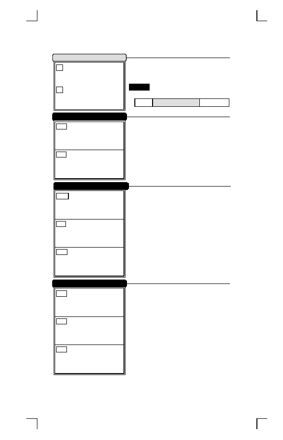
Add-on Insertion Data
Insertion2 Data
Add-on Insertion
Insertion1 Data
The scanner offers 2 characders
of insertion between WPC and add-on
code.
Format
WPC Add-on Insertion
Add-on
The scanner offer 4 positions and
8 characters to insert among the
symbol. The position default value is
"00" to indicate no character
insertion.Beside, make sure insertion
positions are not greater than the
symbols, otherwise the insertion datas
are no effect.
ABD
Data1
*ABD*
(Range:00
16
-FF
16
ASCII Code)
ABE
Data2
*ABE*
(Range:00
16
-FF
16
ASCII Code)
BC X
Position2
*BCX*
(Range:01
10
-48
10
)
ABN
Data1
*ABN*
(Range:00
16
-FF
16
ASCII Code)
ABO
Data2
*ABO*
(Range:00
16
-FF
16
ASCII Code)
IIA
Disable
*IIA*
IIB
Enable
*IIB*
BCW
Position1
*BCW*
(Range:01
10
-48
10
)
ABL
Data1
*ABL*
(Range:00
16
-FF
16
ASCII Code)
ABM
Data2
*ABM*
(Range:00
16
-FF
16
ASCII Code)
PROGRAM
*/$%STR*
Character Insertion
Operation Manual
62
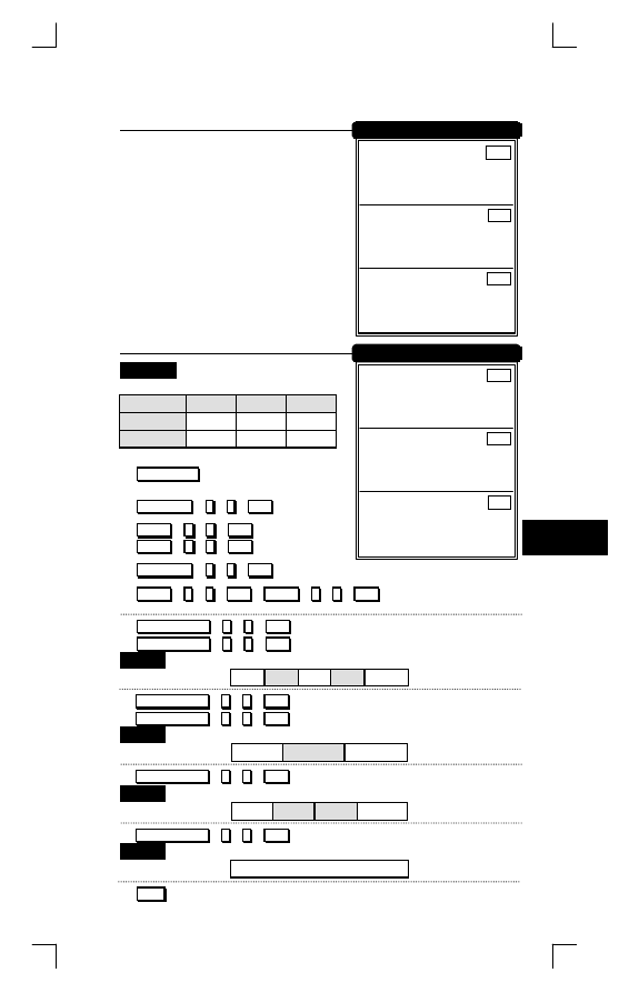
Example
Barcode "1234567"
Postion Data1
Data2
Insertion1
2
A
B
Insertion2
5
C
D
1)
P ROGRAM
ï
Entry programming
2)
P osition1
ï
0
ï
2
ï
S ET
Position1 "2"
2)
D ata1
ï
4
ï
1
ï
S ET
ï Insertion1
D ata2
ï
4
ï
2
ï
S ET
ï Data "AB"
4)
P osition2
ï
0
ï
2
ï
S ET
Position2 "5"
5)
D ata1
ï
4
ï
3
ï
S ET
ï
D ata2
ï
4
ï
4
ï
S ET
ï Insertion2 Data "CD"
6)
I nsert Group
ï
1
ï
2
ï
S ET
Insertion1 and Insertion2
or
I nsert Group
ï
2
ï
1
ï
S ET
Output
12
AB 345 CD
67
6)
I nsert Group
ï
0
ï
1
ï
S ET
Insertion1 only
or
I nsert Group
ï
1
ï
0
ï
S ET
Output
12
AB
34567
6)
I nsert Group
ï
1
ï
1
ï
S ET
Insertion1 outopt twice
Output
12
AB
AB
34567
6)
I nsert Group
ï
0
ï
0
ï
S ET
insertion off
Output
1234567
7)
E XIT
Exit Programming
Position3
BCY
*BCY*
(Range:00
10
-15
10
)
Data1
ABP
*ABP*
(Range:00
16
-FF
16
ASCII Code)
Data2
ABQ
*ABQ*
(Range:00
16
-FF
16
ASCII Code)
Insertion3 Data
Position4
BCZ
*BCZ*
(Range:00
10
-15
10
)
Data1
ABR
*ABR*
(Range:00
16
-FF
16
ASCII Code)
Data2
ABS
*ABS*
(Range:00
16
-FF
16
ASCII Code)
Insertion4 Data
EXIT
Character Insertion
*/$%END*
63
String Format
5
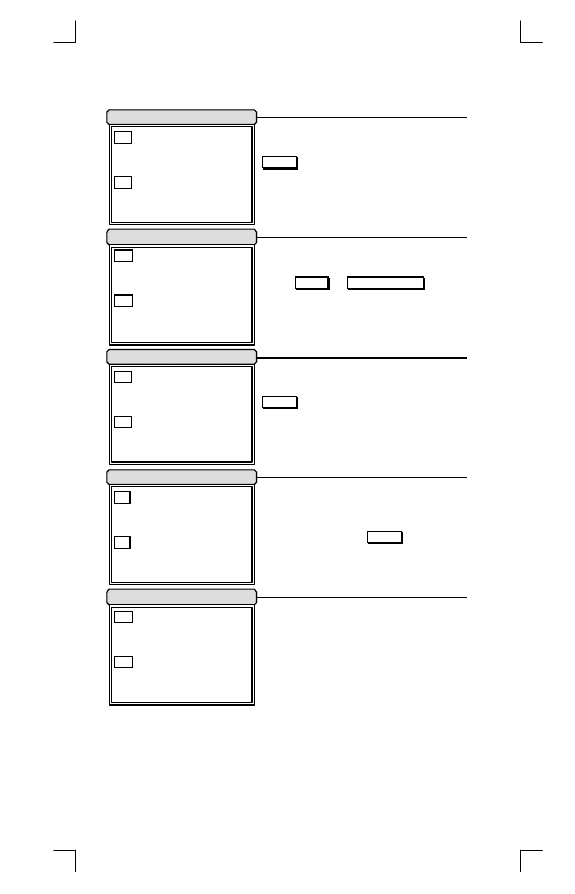
Code ID Position
Code Name Transmission
Length Transmission
Spare Function
Code ID Translation
If your application want to
transmite Code ID, you must set this
E nable
.
Upon your usage, the transmitting
position of Code ID can be selected to
place
B efore
or
After Code Data
when it
transmitted.
A number of data digits can be
transmitted before the code data when
E nable
is selected. The total length is
a number of barcode datas except
Truncate Leading/Ending Digits. And
the length has two digits.
This function is useful to show
unknown barcode symbologies which
include all readable symbologies of
the scanner. When
E nable
is selected,
Code Name will be transmitted before
code data, then you will know what
kind of barcode symbology is.
IBA
Disable
*IBA*
IBB
Enable
*IBB*
ICA
Before Code Data
*ICA*
ICB
After Code Data
*ICB*
IKA
Disable
*IKA*
IKB
Enable
*IKB*
IJA
Disable
*IJA*
IJB
Enable
*IJB*
IDA
Disable
*IDA*
IDB
Enable
*IDB*
PROGRAM
*/$%STR*
Other Control
Operation Manual
64
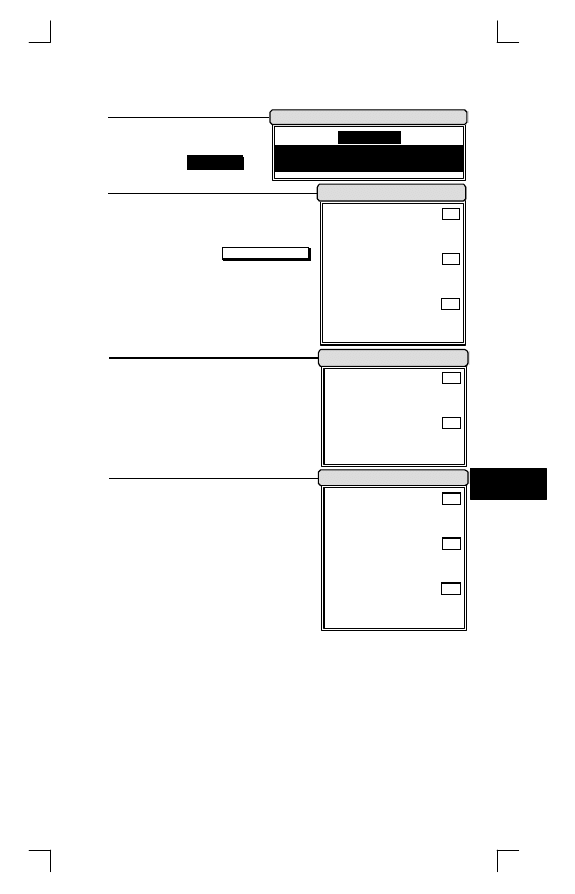
PROGRAM
*/$%STR*
If scanner is operated in
inverse barcode reading,
use inverse
P ROGRAM
to
entry scanner programming.
Generally, the scanner can only
read positive barcode signals which
are printed black on white (call normal
barcode). By setting
I nverse Barcode
,
the scanner will read negative barcode
which bars are printed with light color
and spaces with dark color (call
inverse barcode). This function is
optional for some special models.
Last barcode data can re-send
with trigger. It’s only for Timeout Off,
Timeout Flash and Continue scanning
mode during the light source is on. In
other way, if light is off, last barcode
data will be clear and re-send invaild.
Normal Barcode
IPA
*IPA*
Inverse Barcode
IPB
*IPB*
Normal & Inverse
IPC
*IPC*
Normal/Inverse Barcode
Inverse PROGRAM
Re-send with Trigger
Disable
IQA
*IQA*
Enable
IQB
*IQB*
Ratio Adjustment
1:2.5
IOA
*IOA*
1:1.35
IOB
*IOB*
1:1.5
IOC
*IOC*
EXIT
Other Control
*/$%END*
65
String Format
5
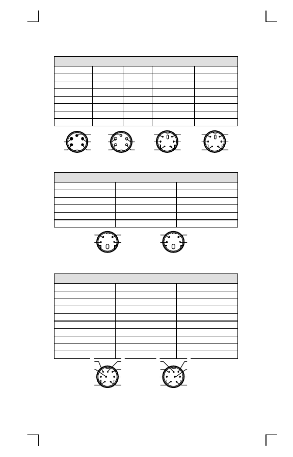
Cable Type
IBM PC, XT, AT & PS/2
Function
5p Din(M) 5p Din(F) 6p Mini Din(M)6p Mini Din(F)
Clock (Host)
1
---
5
---
Data (Host)
3
---
1
---
Clock (KBD.)
---
1
---
5
Data (KBD.)
---
3
---
1
Ground
2
2
3
3
GND Shield
2
2
3
3
VCC (+5V)
4
4
4
4
1
2
3
4
5
5
4
3
2
1
4
6
5
3
1
2
3
5
6
4
2
1
5p Din(M)
5p Din(F)
5p Mini Din(M) 6p Mini Din(F)
Macintosh
Function
4p Mini Din(M)
4p Mini Din(F)
RST (Host)
2
2
Data (Host)
1
1
Ground
4
4
GND Shield
4
4
VCC (+5V)
3
3
2
4
1
3
1
3
2
4
4p Mini Din(M)
4p Mini Din(F)
NEC 9801
Function
8p Mini Din(M)
8p Mini Din(F)
Ready (Host)
4
---
Data (Host)
3
---
Reset (Host)
1
1
Retry (Host)
5
5
Ready (KBD.)
---
4
Data (KBD.)
---
3
Ground
2
2
GND Shield
2
2
VCC (+5V)
8
8
5
8
7
6
3
1
2
4
3
4
6
7
5
2
1
8
8p Mini Din(M)
8p Mini Din(F)
Operation Manual
66
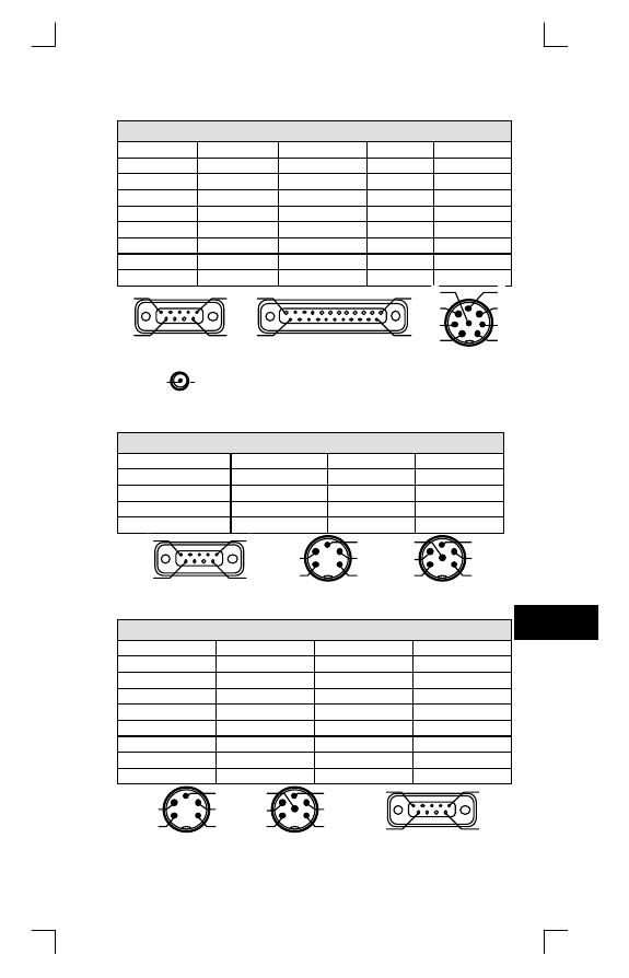
Cable Type
RS-232C
Function
9p D-Sub(F) 25p D-Sub(F) 8p Din(M) DC Jack(M)
TxD
2
3
1
---
RxD
3
2
2
---
RTS
8
5
3
---
CTS
7
4
4
---
Shorted
4,6
6,20
---
---
Ground
5
7
7
2
GND Shield
5
7
7
2
VCC (+5V)
9
16,25
8
1
9
5
1
6 25
13
1
14
1
4
2
5
3
6
7
8
9p D-Sub(F)
25p D-Sub(F)
8p Din(M)
2
1
DC Jack(M)
Wand Emulation
Function
9p D-Sub(F)
5p Din(M)
6p Din(M)
Data
2
2
2
Ground
7
3
3
GND Shield
8
3
3
VCC (+5V)
9
1
1
9
5
1
6
1
2
3
4
5
1
2
3
4
5
6
9p D-Sub(F)
5p Din(M)
6p Din(M)
TTL (CMOS)
Function
5p Din(M)
6p Din(M)
9p D-Sub(F)
Start Of Scan
---
6
1
Data
2
2
2
Indicator
---
---
3
Trigger
5
5
5
Enable
4
4
6
Ground
3
3
7
GND Shield
3
3
8
VCC (+5V)
1
1
9
1
2
3
4
5
1
2
3
4
5
6
9
5
1
6
5p Din(M)
6p Din(M)
9p D-Sub(F)
67
Cable Type
6
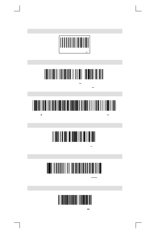
Test Chart
UPC-A
000012345670
EAN-13 (ISBN) with Add-on 5
9 7 8 9 5 7 2 2 1 6 6 7 5
0 0 4 2 0
( I S B N : 9 5 7 2 2 1 6 6 7 8 )
Code-39 (Full ASCII Code)
* C O D E 3 9 T + E + S + T *
( F u l l A S C I I C o d e : * C O D E 3 9 T e s t * )
Interleaved 2 of 5
1 2 3 4 5 6 7 8 9 0 5
Code-93
C O D E 9 3 T E S T Y d
Code-128 (C Type)
0 1 2 3 4 5 6 7 8 9 e
( U C C / E A N - 1 2 8: ] C 1 0 1 2 3 4 5 6 7 8 9 e )
Operation Manual
68
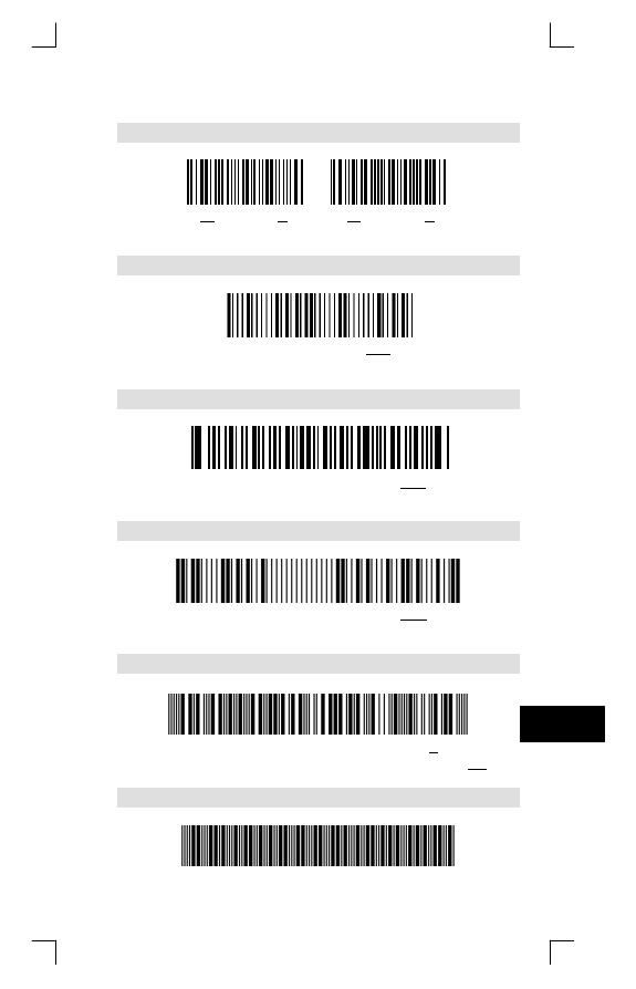
Test Chart
Codabar/NW7
C 9 8 7 6 5 D
D 4 3 2 1 0 A
MSI/Plessey
1 0 5 5 8 3 0 2 5
CODE-11
8 8 6 2 6 4 7 7 7 9 7 3 3
UK/Plessey
1 6 5 2 0 0 0 3 5 4 6 1
Telepen
T E L E P E N T e s t +
(Numeric: 57424942534251055774888916)
IATA
0 0 1 0 2 0 0 0 0 1 0 9 1 9 6
69
Test Chart
7

Operation Manual
70
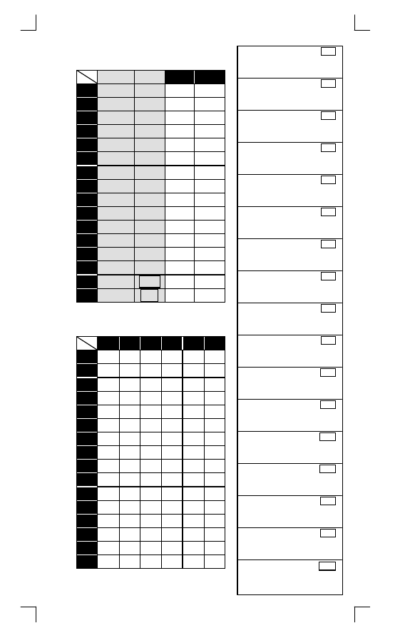
ASCII Code Table
L
H
0
1
0
1
0
Null
NUL
DLE
1
Up
F1
SOH
DC1
2
Down
F2
STX
DC2
3
Left
F3
ETX
DC3
4
Right
F4
EOT
DC4
5
PgUp
F5
ENQ
NAK
6
PgDn
F6
ACK
SYN
7
F7
BEL
ETB
8
Bs
F8
BS
CAN
9
Tab
F9
HT
EM
A
F10
LF
SUM
B
Home
Esc
VT
ESC
C
End
F11
FF
FS
D
Enter
F12
CR
GS
E
Insert
Ctrl+
SO
RS
F
Delete
Alt+
SI
US
*
n
For keyboard wedge only.
L
H
2
3
4
5
6
7
0
SP
0
@
P
`
p
1
!
1
A
Q
a
q
2
“
2
B
R
b
r
3
#
3
C
S
c
s
4
$
4
D
T
d
t
5
%
5
E
U
e
u
6
&
6
F
V
f
v
7
‘
7
G
W
g
w
8
(
8
H
X
h
x
9
)
9
I
Y
i
y
A
*
:
J
Z
j
z
B
+
;
K
[
k
{
C
,
<
L
\
l
|
D
-
=
M
]
m
}
E
.
>
N
^
n
~
F
/
?
O
_
o
DEL
0
%00
*%00*
1
%01
*%01*
2
%02
*%02*
3
%03
*%03*
4
%04
*%04*
5
%05
*%05*
6
%06
*%06*
7
%07
*%07*
8
%08
*%08*
9
%09
*%09*
A
%0A
*%0A*
B
%0B
*%0B*
C
%0C
*%0C*
D
%0D
*%0D*
E
%0E
*%0E*
F
%0F
*%0F*
SET
%OK
*%OK*
71
Wyszukiwarka
Podobne podstrony:
KZ BD w09 id 256667 Nieznany
bd lab2 id 81995 Nieznany (2)
bd dbastudio id 81961 Nieznany (2)
KZ BD w07 id 256666 Nieznany
KZ BD w14 2 id 256670 Nieznany
bd w1 id 81977 Nieznany (2)
KZ BD w12 id 256669 Nieznany
KZ BD w03 2 id 256664 Nieznany
KZ BD w11 2 id 256668 Nieznany
KZ BD w09 id 256667 Nieznany
bd lab2 id 81995 Nieznany (2)
bd dbastudio id 81961 Nieznany (2)
BD 1st 2 4 lab3 tresc 1 1 id 81 Nieznany
bd lab 04 id 81967 Nieznany (2)
Calosc BD id 108184 Nieznany
BD 2st 1 2 w13 tresc 1 1 id 819 Nieznany (2)
BD 1st 2 4 lab1 tresc 1 1 id 81 Nieznany (2)
BD 1st 2 4 lab4 tresc 1 1 id 81 Nieznany (2)
neurochemia konspekt BD id 3173 Nieznany
więcej podobnych podstron