
HIGH SPEED STEEL PRODUCED
THROUGH CONVENTIONAL CASTING,
SPRAY FORMING AND POWDER METALLURGY
R. A. Mesquita and C. A. Barbosa
Villares Metals S. A., Sumar´e, Brazil.
Rua Alfredo Dumont Villares, n. 155, Sumar´e-SP, Brazil
CEP: 13177-900
Abstract
Powder Metallurgy and Spray Forming have been reported as important al-
ternative routes for tool steel production. The ability to promote refined and
more uniform microstructures is their main advantage, leading to improved
properties and higher isotropy. While PM application is a completely estab-
lished technology the Osprey process may be considered as a not totally ex-
plored field. Therefore, the present work aimed to study the potential of both
processes, focused in high speed steel (HSS) production. VWM3C (AISI
M3:2) was produced by conventional casting, Osprey process and powder
metallurgy (Sinter 23). Conventional ingots and a 400 mm diameter Osprey
billet were rolled to large diameter bars, with cross section around 110 mm.
The PM material was evaluated in the as-HIPed condition, in comparative di-
ameters. Large diameter HSS bars are mainly employed in cutting tools, but
are also applied in cold work tooling when higher wear resistance is required.
In the present characterization, microstructures and bend test analysis were
employed, in transverse and longitudinal directions. The results show that the
as-HIPed PM material presents finer and more uniform carbide distribution,
leading to a complete isotropy and higher toughness than the conventional
steel. In the Osprey material, carbides are also finer, well distributed and the
isotropy is considerably higher than that for conventional HSS.
Keywords:
High speed steel, Powder metallurgy, Spray forming, Isotropy, Bend test
387

388
6TH INTERNATIONAL TOOLING CONFERENCE
INTRODUCTION
High speed steels (HSS) forms a special class of highly alloyed tool steels,
combining properties such as high hot hardness and high wear resistance.
These properties are possible to be attained due to a special microstructure,
composed of a matrix around 65 HRC and hard primary carbides, rich in
molybdenum, tungsten and vanadium.
The cast structure of conventional HSS contains coarse carbide arranges,
which makes the material not useful [1]. After certain hot working degree,
the carbide particles are finer and more separated, but are contained in bands
or cells parallel to working direction [1]. These carbide arrangements re-
duce toughness and produce anisotropic properties, which may also cause
distortion after heat treating [1, 2].
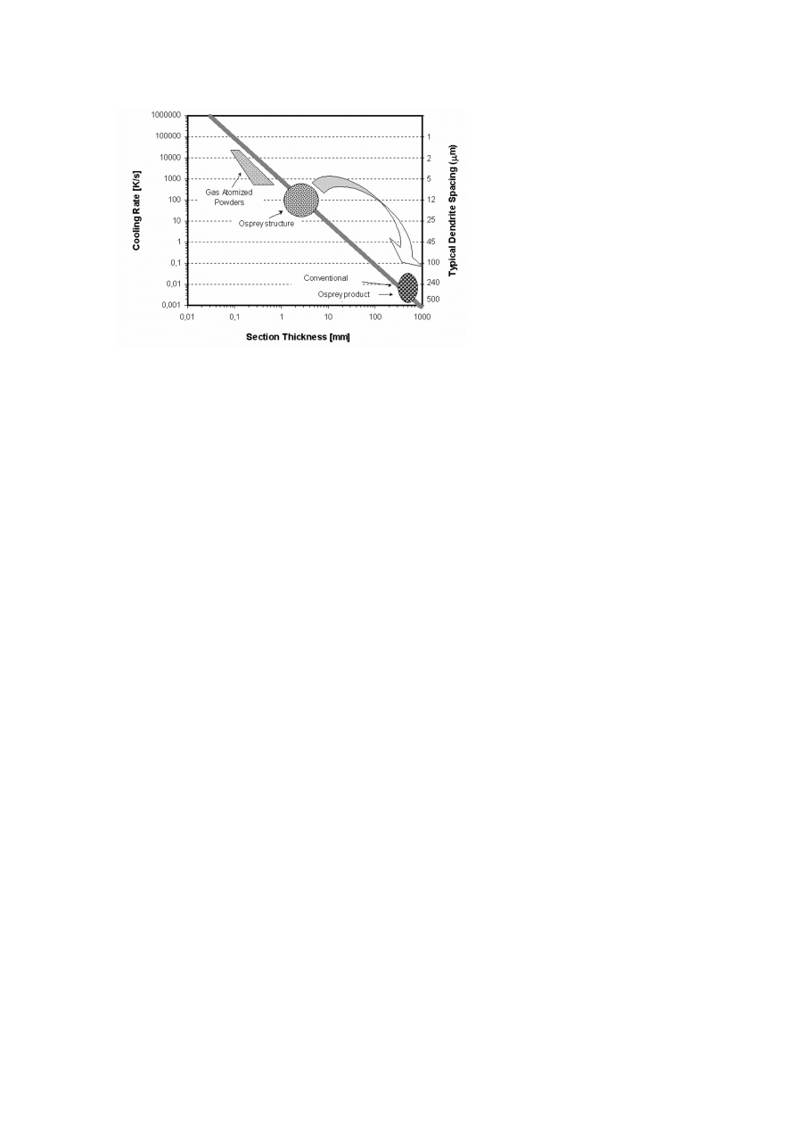
The above discussion is based on assumption that cooling rates were
reasonably slow. Present-day techniques are available to cover an extremely
wide range of cooling rates, which can have a profound effect on as-cast
structure. In normal ingot casting practice the cooling rate may be as low as
10
−3 ◦
C per second. In the consumable electrode processes such as ESR or
VAR, the values are of the same order [2]. However, in powder production
and spray deposition, cooling rates up to 10
5 ◦
C /s may be attained [2]. A
relative comparison of all these processes is shown in Fig. 1 [3]. The right
axis makes an approximate relation regarding the dimension produced.
Powder Metallurgy (PM) was the first industrially application of the ben-
efits of refining by expressive increase in cooling rate during solidification.
Finer primary carbides, smaller grain sizes and absence of carbide stringers
are some characteristics attained [4, 5]. As result of such microstructure,
they have higher toughness, higher hardness after heat treating and are more
isotropic [4, 5]. Another advantage of PM is the possibility of producing
any combination of alloy composition; for conventionally produced HSS,
however, the chemical composition arrange is limited by hot workability
[1, 2].
PM HSS may be produced by various processes, being the most usual
the ASP, CPM and APM process. The differences in PM processes mainly
regards to Hot Isostatic Pressing (HIP) techniques. As discussed in previous
works [6, 7], the APM process has some advantages, since it is able to
produce as-HIPed PM HSS free from porosity and with no segregation of
S, O or C. This is possible thanks to a cold loaded mega-HIP system, where
High Speed Steel ProducedThrough Conventional Casting,Spray Forming and Powder Metallurgy
389
Figure 1.
Effect of cooling rate on microstructure refinement and section thickness. PM,
conventional ingot casting and Osprey process are indicated [3].
pressure and temperature are raised simultaneously [6]. As APM steel is
not subjected to any later forming process, it is considered the only truly
isotropic PM high speed steel [6].
PM has been applied in several situations due to success in refining HSS
microstructure. In spite of its better performance in many cases, wide appli-
cation of PM HSS is limited by the relatively elevated cost of such products.
The large number of operations, especially the HIPing step, has considerably
high cost, which impairs the total PM material cost.
The advantage of spray forming process (also known as Osprey process)
in relation to PM is based on this point. As shown in Fig. 1, PM or other
rapid solidification techniquies, the refined microstructure always relate to
reduced sizes. On the other hand, the Osprey Procss is unique in combining
a rapid solidification process (gas atomization) with a direct method for
making bulk components. Since its development [8], Osprey process has
been widely studied in several types of alloys, being today presented in
usual books and handbooks [1, 2, 9]. Although this technology is not as
technologically applied as powder metallurgy, there are several reports of its
use for high speed steel production [10, 11, 12]. Besides, Osprey process
390
6TH INTERNATIONAL TOOLING CONFERENCE
has been used industrially applied in Rolling Mill Rolls, of high speed steels,
definite chilled iron or spheriodal graphite iron [13].
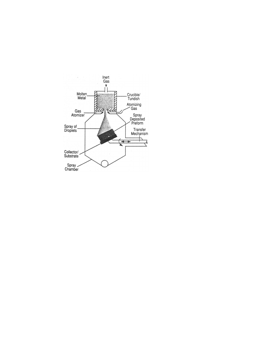
There are four main stages in Osprey Process, including melting and
dispersing, gas atomization, deposition and collector manipulation.
An
overview of the Process, with a single atomizer and applied to billet pro-
duction, is shown in Fig. 2 [14]. For HSS production, the melt is normally
Figure 2.
Schematic description of Osprey process [14].
atomized by supersonic N
2
gas. With the single atomizer, the billet size
was limited to 175 mm diameter [15]. Considering the relativly high initial
porosity, such small billet diameters could be a problem for production of
fully dense bars, specially in sizes higher than 50 mm. However, in 1996,
the development of double atomized spray forming made possible the pro-
duction of billets in diameters up to 400 mm.
Therefore, due to the advances of PM on HSS quality and the possibility
of large billet production in Osprey process, the present work aimed to
compare microstructures and mechanical properties of AISI M3:2 produced
from these two processes. The PM material, named Sinter 23, was produced

High Speed Steel ProducedThrough Conventional Casting,Spray Forming and Powder Metallurgy
391
through APM process, being in the as-HIPed condition. All results are
compared to conventional wrought HSS of the same grade, which is named
VWM3C.
MATERIALS AND METHODS
All materials studied here were in bar diameters around 110 mm. The
conventional M3:2 (VWM3C) partied from cast ingots, which were wrought
conformed to 116 mm square bars. The Osprey M3:2 was produced in a
400 mm round billet, spray formed through a double atomizer equipment.
The as-cast billet was forged to 200 mm squared bar, and rolled to 116 mm.
One rolled bar was also rolled to 11.11 mm. Some properties of this material
are also presented. As-HIPed M3:2 (Sinter 23), produce through APM
process, was also evaluated, in a finished 76 mm bar. As Sinter 23 is in the
as-HIPed condition, the diameter is less important than that of conventional
or even that of spray forming. This size is thus perfectly comparable.
Chemical compositions of all materials are presented in Table 1. The
Table 1.
Chemical composition of PM Sinter 23, Osprey M3:2 and wrought V WM3C.
Weight percent and iron balance
C
Si
Mn
Cr
Mo
W
V
S
P
Sinter 23
1.32
0.63
0.35
4.02
4.95
6.00
2.97
0.006
0.025
OspreyM3:2
1.14
0.54
0.26
4.04
4.91
5.86
2.94
0.005
0.025
VWM3
1.17
0.51
0.25
4.11
4.94
5.87
2.75
0.001
0.027
AISI M3:2
Min
1.17
6 0
.
45
6 0
.
40
3.80
4.70
6.00
2.70
6 0
.
03
6 0
.
03
Max 1.27
4.50
5.20
6.70
3.20
AISI M3:2 composition is also presented for comparison. It is important
to mention that, although the vanadium content of Osprey material is in
the middle of the AISI range, the carbon content is in the minimum limit.
The Osprey material is thus expected to have higher tendency to VC carbide
formation. As a consequence, the equivalent carbon content in solution after
austenitizing, is lowered. This material is thus less able to promote hardness,
by sencondary hardening, than the others.
The heat treatment consisted in heating in the range of 1080 to 1220
◦
C for
5 min, followed by oil quenching. All tempering treatments were conducted
at 560
◦
C , being a double of 2h for conventional and Osprey M3:2 and
triple 1.5h for Sinter 23. As will be discussed later, Sinter 23 presented

392
6TH INTERNATIONAL TOOLING CONFERENCE
higher carbide dissolution, which can increase the retained austenite content.
Because that, three tempering treatments were employed to this material. All
heat treatments were performed under vacuum.
The maximum austentitizing temperature for Sinter 23 was 1180
◦
C , be-
cause this temperature is able to produce considerably high hardness, ade-
quate for all applications. As presented later, the hardness levels attained
after hardening at 1180
◦
C and tempering are higher than those of Osprey
or Conventional VWM3C hardened from 1220
◦
C and tempered. Besides,
as Sinter 23 is a PM HSS, temperatures higher than 1180
◦
C are inadequate,
causing excessive grain and carbide coarsening.
Toughness evaluation was conducted using the bend test method devel-
oped [16] and commonly applied [7, 17, 18, 19, 20] to hardened tool steels.
Bend strength values can be directly related to toughness, as shown in other
reports [17, 18, 19, 20]. Bend specimens with dimension 5 mm× 7 mm×
65 mm were employed, and bend toughness was evaluated in transverse and
longitudinal directions, in order to quantify the anisotropy. Toughness was
analysed in specimens with hardeness around 64.5 HRC.
RESULTS AND DISCUSSION
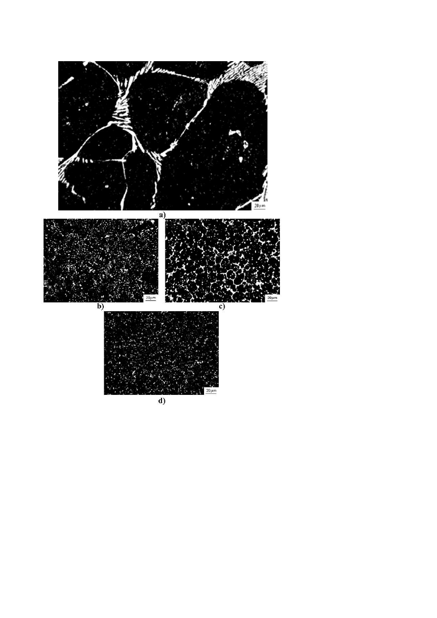
The as-cast microstructures of a conventional HSS, Sinter 23 and the
Osprey M3:2 can be compared in Fig.3. The finer microstructure of PM
material is clearly visible (compare Fig.3a and 3d). This is a result of the
higher cooling rates, discussed before (see Fig.1).
The Osprey material microstructure shows considerable differences be-
tween the dense and porous regions (Fig.3b and 3c). In spray forming, it is
well established [10, 15, 21] that porous regions result from particles that
solidified large part of their volume during the flight, i.e. in contact with
the gas, and reach the substrate with just a small amount of liquid left. As
result, microstructures become finer (Fig.3b), approaching to that of PM ma-
terial (Fig.3d), which is fully solidified in gas atomisation. Higher density
is provided when particles reach the substrate with more liquid. However,
the cooling rate is decreased and the carbide arranges are coarser (Fig.3c).
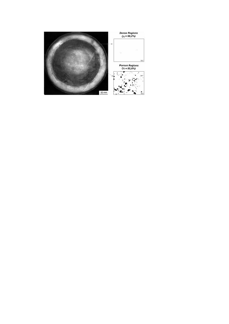
A macrographic view of Osprey billet cross section is presented in Fig.4,
where the dense or porous regions can be identified. Dense regions form
a ring like distribution, near the surface. As discussed, dense regions are
result of liquid concentration occurring during the spray forming process.
This phenomenon is named as shadow and may happen when two atomizers
High Speed Steel ProducedThrough Conventional Casting,Spray Forming and Powder Metallurgy
393
Figure 3.
As-cast structures of a) Conventional VWM3C, b) porous and c) dense regions
of Osprey M3:2 billet and d) PM Sinter 23.
394
6TH INTERNATIONAL TOOLING CONFERENCE
Figure 4.
Macrographic aspect of cross sectioned Osprey billet. Porous and dense regions
are indicated, including relative density.
are employed in spray forming. In dense parts, particles proceeding from
the two atomizers may be concentrated, provoking liquid accumulation and
forming, as a consequence, a dense region in the as-sprayed structure.
In spite of the differences in some regions, the as-cast Osprey M3:2 pre-
sented a microstructure considerably finer than that of conventional mate-
rial(see Fig.3. This results from the better capacity of heat extraction, during
solidification in the Osprey process. The ability of production of such fine
microstructures in a single process, without HIPing processes, is the main
goal of Osprey process.
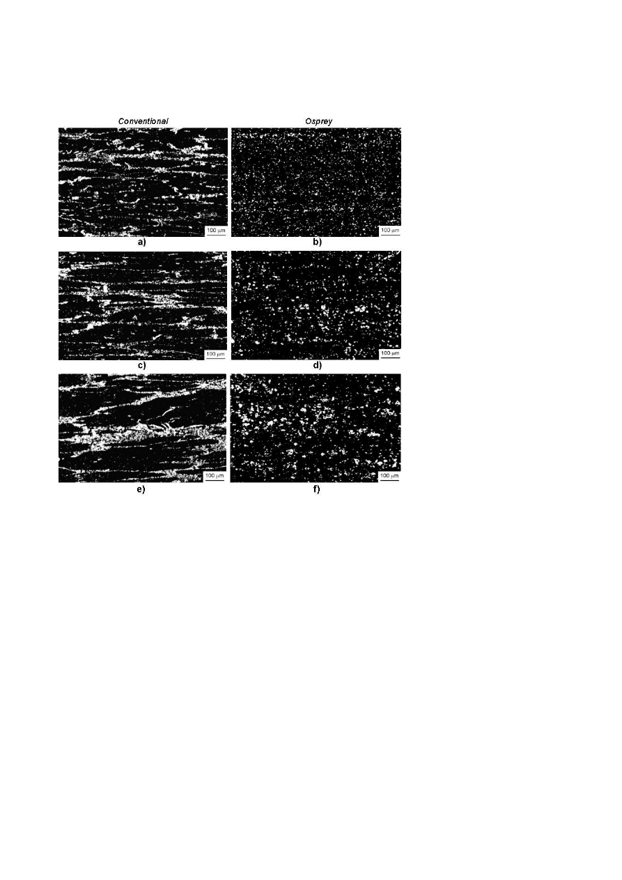
Figure 5 presents annealed microstructures of Osprey and Conventional
M3:2 rolled to 116 mm square size. Surface, mid-ray and core regions
microstructures were analysed. The PM material, in the as-HIPed condition,
can be compared by microstructure of Fig.3d, which is constant throughout
transverse section.
Comparing Osprey and Conventional M3:2, considerable differences in
relation to carbide distributions are observed. The 116 mm section is con-
sidered a large size for high speed steels, and conventional VWM3C remains
coarsen carbide distributions in cellular or Hooky arranges. In spite of being
usual to conventional high speed steels, this arrange is not desired. Because
of carbides’ high hardness and brittleness, their continuous distributions are
High Speed Steel ProducedThrough Conventional Casting,Spray Forming and Powder Metallurgy
395
Figure 5.
Microstructure of conventional and Osprey M3:2 in annealed condition. a)/b)
are relative to surface, c)/d) to mid-ray and e)/f) for core regions. All micrographs are relative
to longitudinal orientation.

396
6TH INTERNATIONAL TOOLING CONFERENCE
preferable regions to crack propagation. They are thus the microstructural
aspects determining tool failure, when failure by fracture is considered. In
practical applications, this situation is important for large diameter cutting
tools, such as large milling cutters and large broaches. The low tough-
ness determined by such coarse carbide arranges also limit high speed steel
applications in cold work tooling. As discussed before, cold work dies nor-
mally employ tool steel bars in diameters over 60 mm and, in such dies,
the low toughness of conventional HSS is inevitable. Besides, conventional
HSS also present strong variations throughout transverse section. Core mi-
crostructures are considerably coarser, with less deformed carbide cells.
As-HIPed PM Sinter 23 presents primary carbides in a totally individu-
alized arrange. As will be shown later, this microstructure leads to higher
and more uniform properties, specially regarding toughness.
Osprey material microstructure can be target between conventional and
PM material ones. In the opposite of conventional HSS, carbides in Osprey
M3:2 do not form coarse morphologies. The majority of primary carbides are
individualized and are finer. Besides, Osprey M3:2 HSS shows less variation
in microstructure between core and surface (compare Fig.5b, 5d and 5f). This
fact is strictly related to spray forming process. As considerable amounts
of particles solidifies during the "flight" period, final microstructure is less
dependent of the section position than that of conventional HSS. Because of
the coarseless microstructure and small variation throughout section, Osprey
material is considered to be close to PM HSS. However, some differences
still remain.
In Fig.6, scanning electron microscopy of carbides are presented. By
EDS, all carbides may be divided in two types: V rich and W-Mo rich
carbides. Acording to literature [1, 2], the stoichiometry of these carbides
are MC and M
6
C respectively. Thus, after annealing and hardening, all
materials are shown to present the same carbide types, regardless the casting
process. This fact agrees with other reports [4, 5], showing that the increase
in cooling rates only cause the variation of carbide sizes, without changing
the stoichiometry types.
Comparing Fig.6b and Fig.3b and 3c, one can see a sensible variation in
carbide size for Osprey M3:2. In Fig.3, carbide sizes of Osprey material,
especially in the porous regions, are comparable to that of PM. On the other
hand, the same carbide comparison in Fig.6 shows relatively high difference
between them. As the PM material was not hot worked, its microstructure is

High Speed Steel ProducedThrough Conventional Casting,Spray Forming and Powder Metallurgy
397
Figure 6.
Scanning electron microscopy of carbides in a) Conventional, b) Osprey and c)
PM materials. Carbide identification was done by EDS analysis, which indicated that MC
carbides are V rich and M
6
C are W/Mo rich carbides.
the same. The microstructural variation of Osprey HSS shows the occurrence
of carbide coarsening after hot working, possibly during the heating previous
to forging and rolling. Therefore, Osprey HSS is shown to be able to present
more refined microstructures if lower temperatures were employed to its
conformation, which indicates the possibility of process optimisation.
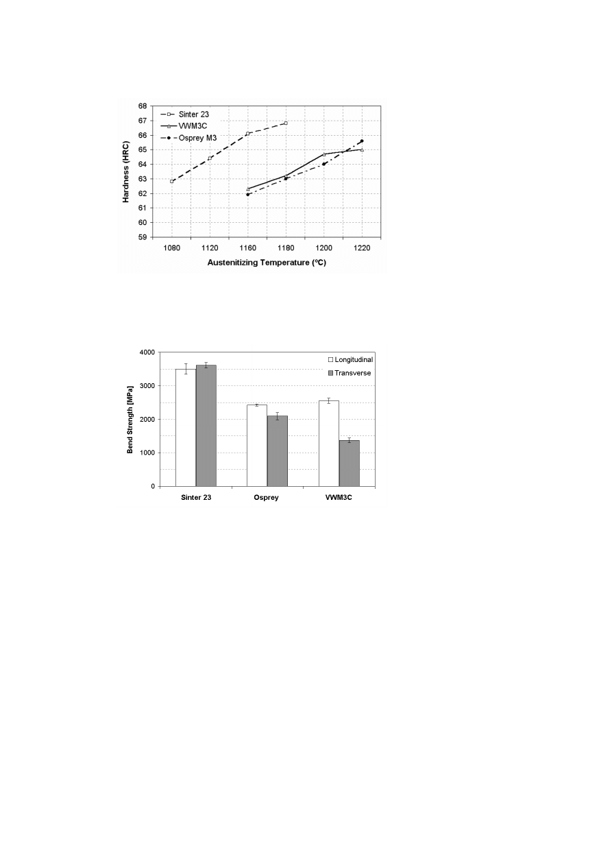
Hardness after tempering is shown in Fig.7, in relation to austenitizing
temperature. For all materials, increase in austenitizing temperature leads
to increased hardness. PM material leads to higher hardness levels, even
in low austenitizing temperatures. In the same way, the Osprey material
present the same hardness levels as conventional HSS, in spite of having
considerably smaller equivalent carbon content. All these phenomena are
related to carbide dissolution kinetics and reprecipitation during secondary
hardening. Finer carbides are more prone to dissolve and thus are indeed
more able to promote higher secondary hardening. The results of Fig.7 are
relevant, showing the first relation regarding casting process, finer structure
and mechanical properties.
Figure 8 presents bend test results for all materials, heat treated for hard-
ness between 64.0 and 65.3 HRC.
In Fig.8, two points may be attained: 1) the general toughness levels and
2) the degree of isotropy for all material. Concerning the first point, it is
clear that PM Sinter 23 is tougher than the others, attaining 40% higher
longitudinal bend strength values.
398
6TH INTERNATIONAL TOOLING CONFERENCE
Figure 7.
Hardness after tempering as a function of austenitizing temperature for PM
Sinter 23, conventional VWM3 and Osprey M3:2.
Figure 8.
Bend strength results for PM Sinter 23, conventional VWM3 and Osprey M3.
The relative difference on longitudinal and transverse directions results indicates isotropy
degree. Considering the experimental, for Sinter 23 isotropy is calculated as 100%, for
Osprey M3 88% and for VWM3C 53%.

High Speed Steel ProducedThrough Conventional Casting,Spray Forming and Powder Metallurgy
399
In HSS, toughness depends on two basic factors: matrix fracture tough-
ness and carbides morphology and distribution. It is considered [20] that
fracture occur after cracking of carbides, which forms subcritical cracks;
with increase loading, crack grows and failure of the specimen occurs when
the crack exceeds the critical length. Based on this, it is possible to affirm
that improved toughness of Sinter 23 results directly form its microstruc-
ture: smaller grain sizes and more uniform and finer distribution of primary
carbides.
It is well known that, under working condition, tools are stressed in com-
plex arrange of forces and they must resist, regardless of the direction of
application. A high degree of isotropy in mechanical properties is thus de-
sirable. Comparing longitudinal and transverse bend strength, it is shown
that PM Sinter 23 is fully isotropic, while Osprey M3:2 presents 88% of
isotropy and conventional VWM3C have only 53% of isotropy. These re-
sults leads to important conclusions, with relation to microstructure.
The full isotropy of Sinter 23 results from its fine microstructure and as-
HIPed condition, as shown in previous work [7]. The higher and isotropic
properties thus improve tool life (retarding failures by cracking), in cutting
or cold work tooling.
In conventional VWM3C, the reduced isotropy is related to the coarsen
carbide network in the microstructure (see Fig.5). For longitudinal stress-
ing, the crack propagates throughout the material crossing the carbide cells.
Based on some reports [7, 20], longitudinal toughness may be attributed to
general carbide sizes, being less sensible to the coarse morphology. As Os-
prey and conventional M3:2 do not have strong variation in this aspect, the
comparable toughness attained may be understood. In transverse stressing,
however, cracking occur when cracks propagate in the same direction of
cells orientation. In this situation, coarsen carbide networks of conventional
material are thus preferential weaker ways for cracking propagation, de-
creasing toughness. For the Osprey M3:2, carbide arranges are less oriented
(see Fig.5), being close the values for longitudinal and transverse direction
strength. Therefore, the Osprey M3:2 present important benefits, regarding
real tooling conditions. In a complex arranges of stresses, better isotropy of
Osprey HSS can conduct to substantial improvements in tool performance.
Coarse carbide arranges also have consequences for heat treatment. Such
regions presents different behaviour regarding thermal expansion and, as a
consequence, may cause distortion. Therefore, PM Sinter 23 and Osprey
400
6TH INTERNATIONAL TOOLING CONFERENCE
M3:2 are also interesting materials considereing this aspect. Their non-
oriented carbide microstructures lead to more isotropic expansion, as well
as occurred for toughness values. It is thus expected that these materials
present less distortion and less problems in relation to heat treatment, which
are common in conventional HSS.
It is important to note that the present work is the first evaluation of Osprey
process on HSS production in large billets. Optimisation of spray deposition
and, as already discussed, billet hot working conditions can produce results
even better than that showed here.
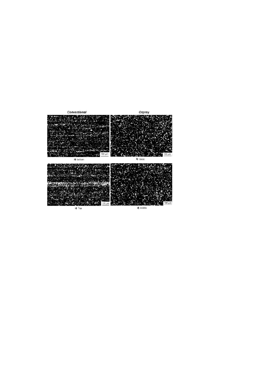
Although it was not the aim of the present work, microstructure compar-
ison of conventional and Osprey material in small sizes (round 11.11 mm
bars) are also presented in Fig.9. One can see that carbide distribution of
Figure 9.
Microstructures of VWM3C and Osprey M3:2, for 11.11 mm round bars. The
regions relative to base and middle Osprey billet or bottom and top ingot are indicated.
Osprey material is absolutely uniform. It was not verified any indications
of carbide stringers and the regions related to base and middle of the billet
have the same aspect. As usual in conventional wrought HSS, all regions
of VWM3C presented carbide stringers, which are thicker for regions re-

High Speed Steel ProducedThrough Conventional Casting,Spray Forming and Powder Metallurgy
401
lated to hot top ingot positions. The absence of carbide stringers is another
advantage of Osprey process for HSS production.
CONCLUSIONS
The characterization of VWM3C production through conventional cast-
ing, Osprey process and powder metallurgy may be summarized in the fol-
lowing points:
Sinter 23 presents fine carbides, which are totally dispersed in non
coarsen morphologies and without orientation throughout longitudinal
direction. This microstructure leads to improved properties and full
isotropy.
Carbide distribution of Osprey material is more disperse than conven-
tional HSS, without coarsen arranges. In small diameter bars, Osprey
material has no carbide stringers.
As a consequence of its microstructure, Osprey material presents
higher transverse direction toughness, in relation to conventional VWM3C,
and 88% of Isotropy.
Sinter 23 is shown as an important option to tool producer considering
reproductively, security in heat treatment and performance aspects.
Osprey HSS microstrucure, properties and isotropy are close to PM
HSS ones. Considering the higher simplicity of Osprey process it is
shown as an interesting route for production of high speed steel and
highly alloyed steels.
REFERENCES
[1] G. Roberts and R. Cary, American Society for Metals, fifth edition, EUA (1998), p.
257-263.
[2] G. Hoyle, in High Speed Steels. E. Butterworths, 1988, 2-47.
[3] P. Mathur et. al, overview, JOM, October (1989), 23.
[4] H. F. Fishimeister et. al., Powder Metallurgy, (25) (1982), 1.
[5] K. S. Kumar et. al., Met. Metall. Trans. A. 22 (1991), 2747.
[6] P. Hellman, Metal Powder Report. 47 (1992), 25.

402
6TH INTERNATIONAL TOOLING CONFERENCE
[7] R. A. Mesquita and C. A. Barbosa. Evaluation of as-HIPed PM high speed steel for
production of large diameters cutting tools. Paper to be published in J. Mater. Sci.
Forum.
[8] Patent GB1972000026307 "Method for Making Shaped Articles from Sprayed Molten
Metal", priority in June 6, 1972. Applicant: OSPREY METALS LIMITED.
[9] Metals Handbook, ASM International, Vol 1, 10th edition, p. 293-295.
[10] Y. Ikawa, I. T. Itami, K. Kumagai and I. Ando, ISIJ International. 30 (1990), 757.
[11] K. H. Baik et. al, Proc. Third International Conference on Spray Forming, (1996),
p.251.
[12] S. Annavarapu, D. Apelian and A. Lawley. Processing Effects in Spray Casting of Steel
Strip. Metallurgical Transactions A, Vol 19, N. 12, p. 3077-3086, 1988.
[13] Sumitomo ’Ospreys" Rolling Mill Rolls. Article in magazine Metal Powder Report,
December 1990, p. 813.
[14] Ogivy, A. J. W, in The metallurgy of the Osprey Process. Internal publication of Osprey
Metals Limited.
[15] A. G. Leatham, A. J. W. Ogilvy, P. F. Chesney. The production of Advanced Materials
by means of the Osprey Process. Modern Developments in Powder Metallurgy, Vol.
18-21, 1988, p. 475-488.
[16] G. Hoyle et. al., J ISI, (1959), 44.
[17] R. A. Mequita and C. A. Barbosa, Proc. of 55§ Congresso Anual da ABM, Brazil
(2000), CD ROM.
[18] S. A. Horton and H. C. Child, Metals Technology (1983), Vol 10, p. 245.
[19] H. Takigawa et. al., Powder Metall (1981),Vol 24, No 4, p.196.
[20] N. Lippmann and H. J. Spies, Proc. of the European Communities ECSC Inf. Day-Eng.
Steels, Dusseldorf Germany (1995), 1.
[21] Morris, Metal Sci. 16(1982), p.457.
Wyszukiwarka
Podobne podstrony:
The Metamorphosis of the Planets by John de Monte Snyders produced by RAMS (1982)
Gail Roarke [Wicked] Bound by Convention (pdf)(1)
Homepower Solar Hydrogen Production by Electrolysis
ELF VLF radiation produced by the 1999 Leonid meteors
78 1101 1109 Industrial Production of Tool Steels Using Spray Forming Technology
82 1159 1179 Advanced Tool Steels Produced via Spray Forming
81 1147 1158 New Generation of Tool Steels Made by Spray Forming
The Official Guide to UFOs Compiled by the Editors of Science and Mechanics first published 1968 (
SMeyer WO8901464A3 Controlled Process for the Production of Thermal Energy from Gases and Apparatus
Prehistoric copper production in the Inn Valley (Austria) and the earliest copper in Central Europe
Encapsulating probiotic bacteria by ultrasonic vacuum spray drying (D Semyonov, O Ramon and E Shimon
Code mutation techniques by means of formal grammars and automatons
68 979 990 Increasing of Lifetime of Aluminium and Magnesium Pressure Die Casting Moulds by Arc Ion
pan wołodyjowski, 29, Atoli Basia od rana nazajutrz odbywa˙a narad˙ z m˙˙em i panem Zag˙ob˙, jak by
BoyerTiCS Religious Thought as a By Product of Brain Function
więcej podobnych podstron