
32
Home Power #39 • February / March 1994
Solar Hydrogen
Production by
Electrolysis
Walt Pyle, Jim Healy, Reynaldo Cortez
©1994 Walt Pyle, Jim Healy, Reynaldo Cortez
W
hy would anyone want to
produce hydrogen at home?
Hydrogen can be used as a
non-toxic energy storage and transport
medium. Hydrogen that is made from
water using solar energy is a
sustainable and renewable home
energy supply. Make hay (or hydrogen)
while the sun shines. Then use the
stored hydrogen to produce heat and
electricity on demand, day or night!
We got excited about solar hydrogen production during
the seventies and the first oil shocks. What happened
between the seventies and nineties? For the most part
we worked with thermolysis (splitting water with
concentrated solar heat) and photoelectrolysis (splitting
water in a liquid solar cell). We also followed the work
of other hydrogen pioneers, such as Roger Billings and
his associates, who produced and used hydrogen in
home appliances and vehicles.
The article by Richard Perez about the Schatz PV
Hydrogen Project (
HP #22, pp. 26–30) and a
subsequent visit to Humboldt State University’s Trinidad
Marine Laboratory launched us into designing and
making a “home-sized” system based on electrolysis of
water. Electrolysis is the competition for thermolysis
and photoelectrolysis at this juncture.
Hydrogen and oxygen can be produced from water
using electricity with an electrolyzer. This article
describes the installation and operation of a 12 cell
Hydrogen Wind Inc. 1000 Watt electrolyzer. This
electrolyzer can produce 170 liters/hour (6 cubic
feet/hour) of hydrogen and 85 liters/hour (3 cubic
feet/hour) of oxygen (at standard temperature and
pressure).
In addition, we describe a homebrew purification and
storage system for the hydrogen and oxygen produced
by the electrolyzer. With proper after-treatment, the
gases produced can be stored safely. The purified
hydrogen and oxygen can be used in fuel cells (to
produce direct current electricity) and catalytic burners
(for heating and cooking) without poisoning or
damaging the noble metal catalyst materials. The gases
can also be used for welding and cutting, as well as for
motor vehicle fuel.
!!!!Safety First!!!!
Making and storing hydrogen and oxygen is not kid’s
stuff — this is “rocket fuel”! Use flashback flame
arrestors on the hydrogen and oxygen outlets from the
electrolyzer. Secure dangerous caustic from small
prying hands. Make sure your gases are pure before
storing them. More on safety follows.
How Much Hydrogen Do I Need?
This varies tremendously from household to household,
depending on how well the Demand Side Management
job has been done. We can run our Platinum Cat space
heater for about three hours on a cubic meter of
hydrogen. The amount of gas needed can be estimated
from the energy consumption of any appliance.
Amanda Potter and Mark Newell’s article in
HP #32 (pp.
42–45) describes the operation of an electrolyzer and
shows how to calculate the amount of gas needed to
run appliances. See articles on hydrogen space heating
in
HP #34, hydrogen cooking in HP #33, and making
electricity from hydrogen with a fuel cell in
HP #35.
How Much Power Does It Take?
A cubic meter (35.3 cubic feet) of hydrogen gas takes
about 5.9 hours to produce in this electrolyzer, when
operated at its rated input power of 1000 Watts. This
means the energy required to produce a cubic meter of
hydrogen and 0.5 cubic meter of oxygen is about 5.9
kW-hr. This translates to an efficiency of 51%, where 3
kW-hr/m
3
equals 100% efficiency at 20°C. Typical
industrial scale plants operate at about 4.5 kW-hr/m
3
or
67% efficiency at high current density. The efficiency is
better at lower current density.
What Is Needed to Produce Hydrogen at Home?
Our system includes the following components and
sub-systems (see the block diagram next page):
• Solar electric power and/or utility grid power
• Power Controller
• Electrolyzer
• Hydrogen Purifier
• Oxygen Purifier
• Hydrogen and Oxygen Storage Tanks
• Electrolyte Storage Tank and Transfer Pump
• Makeup-water Purifier
Hydrogen
33
Home Power #39 • February / March 1994
Hydrogen
Where Can I Get An
Electrolyzer?
The Hydrogen Wind electrolyzer
was introduced by its designer
Lawrence Spicer in
HP #22 (pp.
32–34). Hydrogen Wind Inc.
electrolyzers are available in
single cell units for small demand
or educational use, and in multiple
cell configurations which provide
higher gas production rates.
We purchased a 12 cell 1000 Watt
system with the gas pressure
controls and electrical metering.
Larger systems with up to 24 cells
or smaller three cell and six cell
systems are available. Another
article by Spicer, describing the
individual cells in more detail along
with an introduction to cell arrays,
appears in
HP #26 (pp. 34–35).
The cell electrodes are fabricated
from rectangular metal plates with
tabs on one end. Both the anode
and the cathode metal plates are
made from porous, sintered nickel.
Two clusters of nickel electrode
plates, 14 for the anode and 14 for
the cathode, are separated by
porous plastic sheets folded
accordion style within a separator
container.
The plastic separator container is open at the horizontal ends, and closed at
the top and bottom. This lets the larger hydrogen gas bubbles (which escape
from the negative electrode or cathode) rise in the electrolyte, due to their
buoyancy, and exit the separator container on one side. The hydrogen
remains separate from the smaller oxygen bubbles
which evolve from the positive electrode (anode) and
exit on the opposite side.
The micro-porous polypropylene separator container
and the electrode clusters are housed inside sections
of steel pipe with flat steel plates welded on one end
and bolted on the other end. The steel cell housings
hold the water and potassium hydroxide electrolyte,
and keep the hydrogen and oxygen gases apart after
they rise from each end of the separator container.
We installed our electrolyzer inside a small weather-
protected shelter made from box tubing and sheet
metal. We chose stainless steel sheet metal for its
corrosion resistance to caustic electrolyte and long-
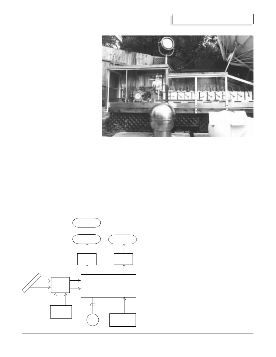
lasting “perma-culture” value. The photograph above
shows an overview of the system.
Solar Power and Utility Grid Backup Power
Our solar electric power is produced by two 16-panel
Carrizo Solar “Mud” photovoltaic arrays and a gaggle
of other smaller panels. On a good summer day we
get up to 75 Amperes at 14 Volts for charging the
Above: An overview of the electrolyzer system. The power supplies and
electrical controls are on the far left. Purification equipment is to the right of
the power controls. The electrolyte reservoir and hydrogen and oxygen float
valves with pressure gauges are to the right of the purification equipment.
Twelve electrolyzer cells are shown on the far right. A feedwater purification
system is just below the twelve electrolyzer cells. The caustic electrolyte
storage tank is on the ground below the float valves.
Photo by Reynaldo Cortez
Solar
electric
modules
Makeup water
purifier
Electrolyzer
Electric
utility grid
Oxygen
purifier
Hydrogen
purifier
Electric
power
controller
Hydrogen gas
Hydrogen gas
Oxygen gas
Electrolyte tank
Solar
Hydrogen
Production
34
Home Power #39 • February / March 1994
Hydrogen
house batteries. When the two house battery banks are
fully charged, our two 50 Amp SCI charge controllers
disconnect the PV power, and the PV voltage rises. An
Enermaxer controller senses the voltage rise and
transfers the PV power to the electrolyzers to make
hydrogen and oxygen during the
remainder of the day. A utility grid
electrolyzer power supply is used to
make hydrogen and oxygen when
there is insufficient solar power
available.
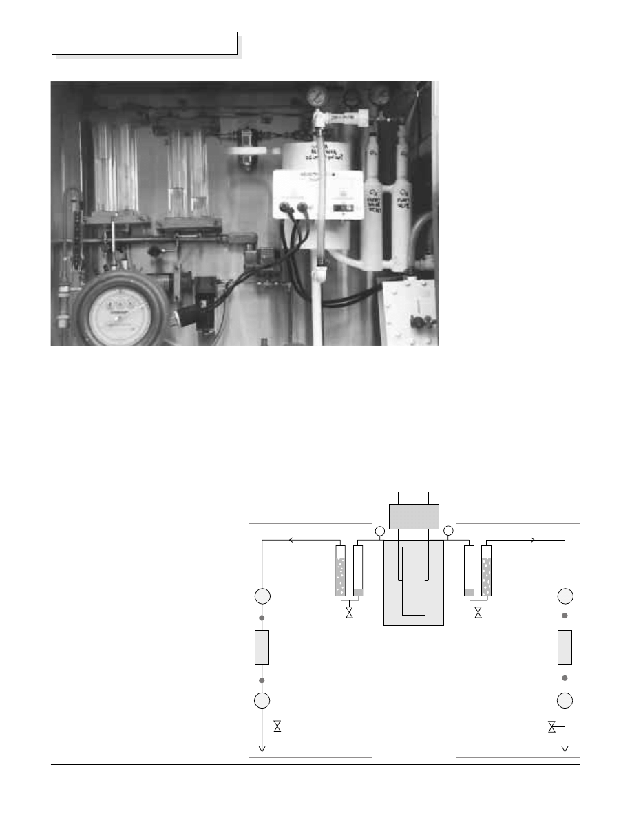
How Do We Purify the Gases?
The gas purification system is shown
in more detail in the diagram on right.
The hydrogen gas and the oxygen gas
are purified by two different systems.
Bubblers
First, each gas is scrubbed by passing
it through a water bubbler column.
Each of the gas scrubbing bubblers is
made from two vertical plastic tubes
with end caps. A pair of fish-aquarium
type bubbler frits was glued into holes
drilled in the inside bottom caps of
each acrylic plastic tube, using
methylene chloride solvent. Flow of
gas into or out of a bubbler can then
be seen by the operator. The bubblers
are filled about one-third full with
distilled water using the
drain and fill valves on the
bottoms.
We call these “Bi-
directional Bubblers”. The
bubblers are tolerant of
flow in any direction,
without letting the scrub-
water into the product
storage system or the
electrolyzer. We got the
idea for making these
bubblers from Dr. Peter
Lehman and his
associates at Humboldt
State University (Schatz
Solar Hydrogen and Fuel
Cell Laboratory.)
The gases entering the
purifier are saturated with
water vapor and may
contain minute amounts of
caustic electrolyte aerosol
and particulates like rust.
After passing through the bubblers the gases are still
saturated with water vapor, but virtually caustic- and
particulate-free. Installing another coalescer before the
bubbler would prevent particulates and some aerosol
from entering the bubblers.
O
2
bubbler
H
2
bubbler
Water
coalescer
Electrolyzer
Fill
Drain
H
2
delivery
O
2
delivery
De-oxygenation
catalytic recombiner
Oxidation catalytic
recombiner
(future)
H
2
purifier
Gas Purification System
Power
Controller
Water coalescer
O
2
purifier
Water
coalescer
Water coalescer
P
P
Sample
Sample
Flashback arrestor
acetylene check valve
Flashback arrestor
acetylene check valve
Flashback arrestor
oxygen check valve
Flashback arrestor
oxygen check valve
Fill
Drain
Above: The bi-directional bubblers and purification systems.
Photo by Reynaldo Cortez
35
Home Power #39 • February / March 1994
Hydrogen
Coalescers
Next, the gases are partially dried by passing them
through coalescing filters. Special materials were
required for the oxygen coalescer filter to prevent
spontaneous combustion, and no oil or hydrocarbons
can be present.
Recombiners
The hydrogen gas purifier treats the hydrogen gas in a
catalytic recombiner. The purpose of the recombiner is
to recombine any oxygen impurity in the hydrogen
product, and make water. The noble metal catalytic
recombiner removes the oxygen impurity to make the
hydrogen gas safe to store and handle. As a safety
measure, we installed flashback arrestors between the
first and second coalescers and the recombiners. The
flashback arrestors prevent flashback of poor purity
gases (oxygen impurity in the hydrogen produced)
when they reach the recombiner and ignition source.
The recombiners must be installed with their major axis
vertical and the entry at the top.
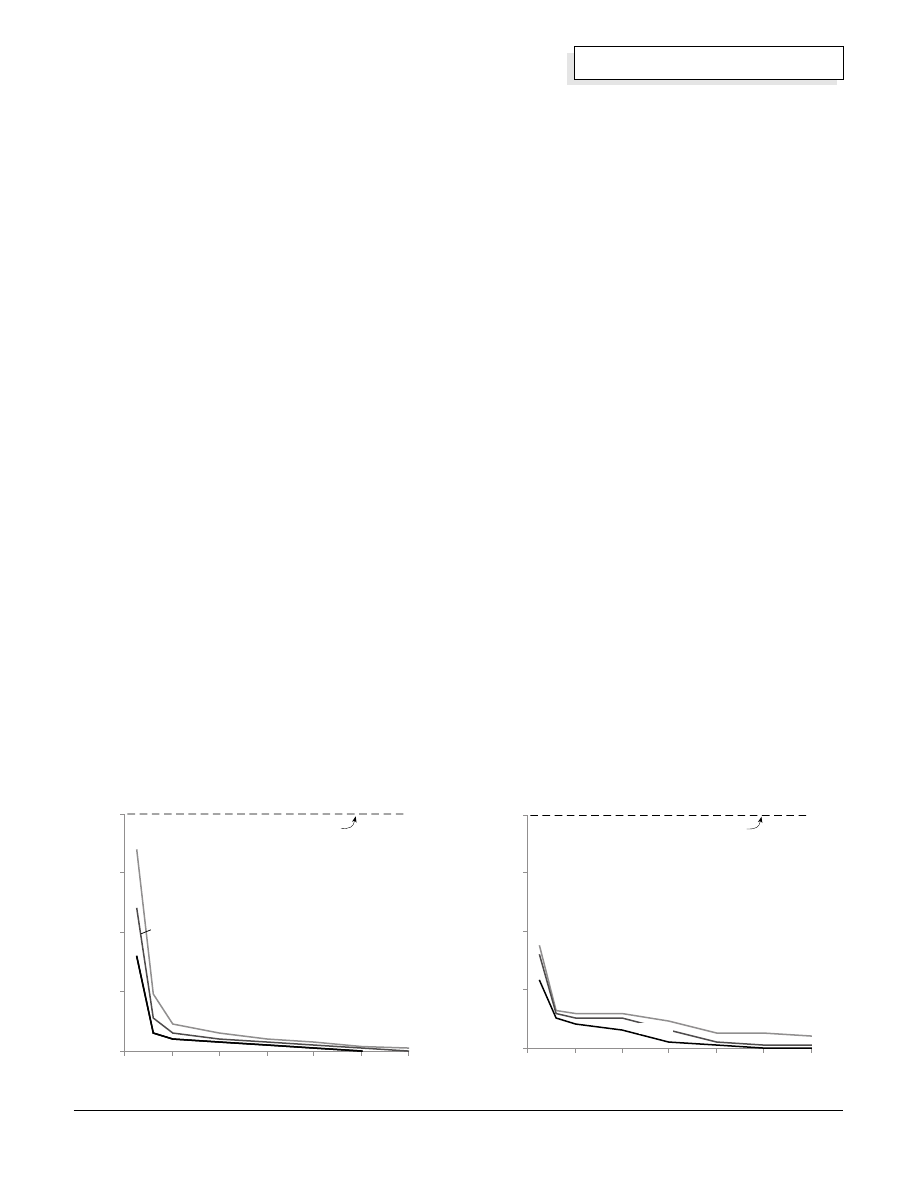
Some data recently published by W. Hug et al from the
German Aerospace Research Establishment
(International Journal of Hydrogen Energy, Vol. 18 No.
12, pp. 973–977) shows that purity of the gases
produced by an alkaline electrolyzer is affected by the
current density and temperature of the cells. From the
graphs we see that the purities of the hydrogen and
oxygen gases are poorer at low current densities (such
as when a cloud covers the sun for example). This is
because diffusion of the gases through the liquid
electrolyte is a more significant fraction of the total
production at low current densities.
The data also imply that there is more danger of having
hydrogen impurity in the oxygen than the reverse. Note
that the lower flammable limit, 4% for hydrogen impurity
in bulk oxygen, is approached at low current densities.
How Does One Store the Gases?
The hydrogen will be stored in two 0.47 cubic meter
(125 gallon) propane tanks, and the oxygen will be
stored in one propane tank.
REMEMBER: hydrogen gas is safe to store —
hydrogen/air or hydrogen/oxygen mixtures are NOT
safe to store! Put safety first! Safety is your
responsibility. It is our intention to give you the
information you need to follow safe practices.
Each of our used propane tanks was cleaned
thoroughly and hydrostatically tested to 13.8 bar (200
psig.). Pressure relief valves on each tank are set for
10.3 bar (150 psig.). A pressure switch is installed on
the hydrogen tank feed line to shut off the electrolyzer
power supply when the pressure reaches 6.9 bar (100
psig.), the rated maximum output pressure of the
electrolyzer.
The produced hydrogen gas is pressurized by the
electrolyzer to its maximum rated pressure of 6.9 bar or
less. Our two hydrogen tanks hold the equivalent of: 6.9
bar x 2 tanks x 0.47 cubic meter = 6.5 cubic meters (at
standard temperature and 6.9 bar pressure).
Makeup-water Treatment System
As hydrogen and oxygen are produced in the
electrolyzer, water is consumed and it must be
replaced. We produce our makeup-water using the
local Utility District water, which is piped into the home.
We want to prevent the formation of “mineral scale” on
the surface of the electrodes inside the electrolyzer
because we want them to last a long time. First, the
Amount of Hydrogen in Oxygen
Current Density (mA/cm
2
)
Gas Impurity H
2
in O
2
(V
ol%)
0
1
2
3
4
0
100
200
300
400
500
600
90
°
C
60
°
C
30
°
C
Taken from measurements by Hug et al,
IJH 18:12, 1993
lower flammable limit
Current Density (mA/cm
2
)
Gas Impurity O
2
in H
2
(V
ol%)
Taken from measurements by Hug et al,
IJH 18:12, 1993
90
°
C
30
°
C
Amount of Oxygen in Hydrogen
0
1
2
3
4
0
100
200
300
400
500
600
lower flammable limit
60
°
C
36
Home Power #39 • February / March 1994
Hydrogen
water is passed through a 20 micron interference filter
to remove particulates like rust and sand. Second, the
water passes through a charcoal drinking water filter to
remove organics and chlorine. Third, the water passes
through a de-ionizing column to remove metallic ions.
The water before and after the purifier was analyzed.
The results are shown in the table above.
As you can see, we removed some scale-forming
material. Other elements were below the lower
detectable level of the instrument (approximately one
ppb). Our water before the deionizer and charcoal filter
is not very “hard” at this location; it does not contain
very many dissolved minerals. After the de-ionizer there
is a marked reduction in elemental concentrations of
everything except silicon.
Why Conduct a Hydrostatic Test on the Electrolyzer?
Prior to filling the electrolyzer with caustic electrolyte,
we conducted a hydrostatic leak test by filling the cells
with purified water and pressurizing the cells and
electrolyte reservoir to 6.9 bar (100 psig) using utility
line pressure. Several tubing fittings leaked until
tightened. Fixing water leaks during the initial
hydrostatic test is much better than fixing leaks when
they involve caustic electrolyte! Getting caustic on your
tools, gloves, safety glasses, and clothes is a real drag.
Plan ahead!
When installing the tubing clamps, position them so you
can tighten them later when the cells are tied together.
An improvement would be to mount the cells higher to
allow for access to the clamps from below.
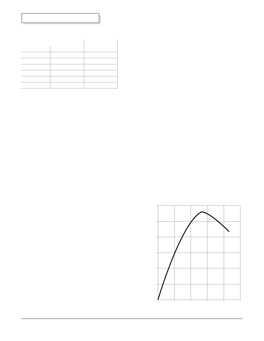
Why Do You Need the Caustic Electrolyte?
Potassium hydroxide (KOH) in the water makes it
electrically conductive, so that ions can be transported
through the electrolyte during electrolysis. See graph
showing the conductivity of the KOH electrolyte as a
function of weight percent KOH in water on right.
We have chosen KOH as the caustic. The twelve
electrolysis cells and the electrolyte reservoir hold
about 61 liters (16 gallons) of water plus 15 kilograms
(33 pounds) of KOH. This solution is about 23% KOH
Water Purification Results
Before
After
Element
Purifier, ppm
Purifier, ppm
barium
0.009
nil
calcium
7.3
0.006
potassium
0.37
nil
magnesium
0.7
nil
sodium
1.8
nil
silicon
3.8
3.8
Concentration % Weight
Conductivity (Siemens/cm @ 20
°
C)
0
0.01
0.02
0.03
0.04
0.05
0.06
0
10
20
30
40
50
Conductivity vs. KOH Concentration
Omega Conductivity and pH Measurement Catalog
by weight. The strength of the electrolyte solution can
be tested with a battery hydrometer. The specific
gravity should be about 1.1.
Safety is a Must When Handling Caustic Electrolyte!
DANGER!! Potassium hydroxide is very corrosive and
hazardous to handle. KOH deserves great respect.
Goggles or safety glasses with side protectors, and
plastic or rubber gloves are absolutely necessary when
handling KOH. When caustic comes into contact with
the skin, the natural oils of the skin are chemically
converted to a soap, which initially gives a slippery
feeling. Prolonged contact will dissolve the skin and
give a chemical burn similar but more severe than that
given by handling lime or fresh wet concrete with bare
hands. The best treatment for any accidental spill is
flushing with copious amounts of water, or
neutralization with a weak acid such as vinegar. Always
have a water hose hooked up and operational before
handling KOH caustic. Keep the electrolyzer outdoors
and locked so only qualified people can service it. A
cyclone fence with top and sides might be the solution.
DANGER!! The mucous membranes of the eye are
especially susceptible to caustic damage. It has been
estimated that 15 seconds of contact to the eye with
concentrated KOH caustic is enough to produce
permanent blindness. If any KOH comes into contact
with the eyes, the best treatment is to flush the eyes
immediately with pure water for at least 15 minutes and
seek medical attention.

37
Home Power #39 • February / March 1994
Hydrogen
What Provisions Need to be Considered When
Handling Caustic?
To service any of the cells, we need a way to drain the
electrolyte and store it for re-use. We have a drain valve
and line on the bottom of the electrolyte reservoir that
allows the KOH solution to gravity drop into a stainless
steel tank at a lower level on the ground. A tubing roller
pump is used to refill the electrolyzer cells with KOH
after the maintenance is completed. Our KOH tank was
previously used as a swimming pool filter case.
We mixed the water and KOH in the ground level
caustic storage tank. Water and KOH mixing produces
chemical heat, the “heat of solution”, which is
surprisingly high. After we mixed in all of the KOH
flakes, the water temperature rose from 20°C (68°F) to
about 82°C (180°F).
At this point we made our first big mistake. After the
KOH and water electrolyte solution was mixed (and
hot), we immediately started pumping it into the
electrolyzer reservoir and cells, using the tubing pump.
Within minutes, the tubing pump began leaking. We
stopped the pump and drained the KOH back to the
ground level tank. After cleaning up the mess, we found
that the silicone tubing had split open. We let the KOH
solution cool overnight. The next day we replaced the
tubing in the pump, and tried again. This time the
transfer proceeded without pump tubing problems.
By the time the caustic was about half pumped into the
cells, we found that six of the tubing fittings on the first
two cells were dripping KOH onto the floor of the
shelter. The hot KOH the night before had damaged
some of the pipe thread seals which were made with
five minute epoxy. The threads in cells further away
from the caustic KOH entry point were not damaged,
presumably because the caustic KOH solution had
cooled by the time it reached those points. We drained
the caustic KOH back to the ground storage tank,
removed the affected fittings and replaced the epoxy
thread sealant. The next day we filled the cells back up
with KOH solution for the third try.
More caustic KOH leaks! This time we had leaks on the
tubing fittings on the gas-trap tubing loops where the
hydrogen and oxygen come out of the cells at the top.
Additional tightening of the tubing clamps with a 12 point
box wrench stopped some leaks. Other fittings had to be
removed and thread epoxy had to be reapplied. When
will solid polymer electrolyte electrolyzer cells be
available at a reasonable price so we won’t have to
hassle with KOH???
What Were the Cell Operating Conditions?
The cells require about 1.7 volts each to begin
operating; at higher currents there is a greater voltage
requirement. The direct current requirement is about 40
Amperes for each cell at rated gas output. In a twelve-
cell system the cells are wired in series, so that all of
the cells get the same current and the voltages add up
to 12 x 1.7 V or 20.4 Volts total at 20 Amperes of
current. The cells can also be wired in series-parallel for
10.2 Volts total.
Our solar photovoltaic system and grid back-up power
supplies can only produce about 25 Amperes at the
moment, so we cannot yet achieve full gas output. The
20.4 Volt operating voltage was not a problem with our
Carrizo solar electric arrays, however, since they have
an open circuit voltage of about 25 Volts.
Strange and Unusual Behavior?
When operating the electrolyzer the first day on direct
current power, the power controller behaved
predictably. We measured about 22 Volts and 25
Amperes flowing into the electrolyzer cells. We had gas
flow only through the oxygen bubbler however!! And
occasionally, the oxygen float valve “burped” some
KOH solution upward with a release of gas. The fix for
this problem was to raise the electrolyte level from
about 5 cm (2 inch) on the reservoir level gauge to 20
cm (8 inch).
At first startup the gas comes out after a delay of about
an hour while the cells are “charging” and the gas
bubbles on the electrodes get large enough to break
away. Voltage across the cell array gradually rises
during “charging” from 18 to 19 to 20 Volts before gas
comes out.
On restart, hydrogen comes out later than oxygen since
it must first fill the top of the electrolyte reservoir tank to
pressure-pump the system. When both gases were
coming out of the electrolyzer pressure control float
valves, the pressure on the reservoir was 2.5 bar (36
psig) when discharging to atmospheric pressure.
The next day we may have had our first personal
demonstration of William Grove’s astonishing
observation that an electrolyzer can run backwards and
become a power source. Grove discovered in the early
19th century that the reverse reaction — supplying
oxygen and hydrogen to electrodes — causes an
electrolyzer to produce direct current electricity and act
as a fuel cell.
Before we turned on our power supply the next day, the
voltmeter showed about 16 Volts DC on the electrolyzer
terminals indicating it was acting as a “source”. After
that we put a resistive load on the electrolyzer leads
and generated about 16 Volts and 10 Amps for several
hours (160 Watts) before it “ran out of gas”. Was the
cell acting as a fuel cell, as an alkaline nickel-iron
battery, or a combination of both?

38
Home Power #39 • February / March 1994
Hydrogen
Grunting and Wheezing Sounds are Normal!
Inside the Hydrogen Wind gas pressure control system
there are three float control valves. Two float valves are
used for the oxygen and one is used for the hydrogen.
When the float valves are filled with gas (vertical acrylic
tubes with top caps), they float on the electrolyte in the
chambers. As each chamber fills with gas the
electrolyte is gradually displaced and the the buoyancy
of the float decreases. When the buoyancy is low
enough, the float falls which releases the elastomer
plug from the exit passage and allows the gas to leave
the system.
The float valves cycle over and over again to release
“bursts” of gas to the purifiers. You can hear grunting
and wheezing sounds when standing alongside the
unit. A little back pressure on the discharge lines makes
the release less violent and quieter. With 1 bar (14.5
psig) back pressure we had good results.
Budget & Economics for Gas Production & Storage
The approximate cost for the solar hydrogen system
equipment is listed below, broken down by sub-system.
The labor used for this installation was our own and
was not tallied. Normally, for a “first time” system such
as this, a rule of thumb is that the labor costs will about
equal the capital equipment costs. Labor on any future
clone would be significantly less. Capital equipment
costs could have been reduced by using fewer stainless
steel and more plastic components.
We didn’t work out the “payout” or ROCE for this
system before going for it. We made it because we
thought it was nifty stuff!
It would probably take quite a while to pay for this
system. However, don’t forget, it’s a prototype. Mass
production has a way of cutting costs by factors of ten.
How does a cloned system capital cost of $678 sound?
Status and Future Direction
Startup of this system occurred during the first week of
December 1993. Our next task is to measure the purity
Hydrogen System Cost
Equipment
Cost
%
12 cell electrolyzer system (incl S&H)
$2,300
34%
Photovoltaic modules (used)
$1,500
22%
Gas storage tanks, relief valves, tubing $1,100
16%
Hydrogen purification system
$950
14%
Oxygen purification system
$350
5%
Caustic storage and transfer
$300
4%
Feedwater purification system
$275
4%
Total $6,775
of the hydrogen and oxygen product gas streams
before we attempt storage.
Eventually, when we have a use for the oxygen gas
product in a large fuel cell, we plan to add an oxidation
recombiner to the oxygen side. This will remove any
hydrogen impurity from the oxygen side and make it
safe to store and handle. For now, we are not storing
the oxygen. Instead, we will supply the oxygen to the
root system of vegetables in some experiments with a
horticultural friend of ours, but that’s another story......
A future article will focus on safe storage of hydrogen
and oxygen. We plan to cover compressed hydrogen
and oxygen gas storage and hydrogen storage in metal
hydride.
Acknowledgements
Alternative Energy Engineering, David Booth and David
Katz, for the upgrade to our Enermaxer power
controller.
Jim Robbers and Mike Robbers for the used stainless
steel swimming pool filter cases which we use for
electrolyte storage.
Access
Walt Pyle, WA6DUR, Richmond, CA • 510-237-7877
Jim Healy, WH6LZ, Richmond, CA • 510-236-6745
Reynaldo Cortez, Richmond, CA • 510-237-9748
Electrolyzer
Hydrogen Wind Inc. RR 2 Box 262, Lineville, IA 50147 •
515-876-5665
Purifier and Storage Components
Hydrogen Coalescer (Coilhose 27C3-S): Weill Industrial
Supply Inc. • FAX 510-235-2405
Bi-directional Bubbler: H-Ion Solar Co. • FAX 510-232-
5251
Flame Arrestors: Check valve flashback arrestor, flash
arrestor body with female inlet check valve. Part # FA-
3CV. Western Enterprises • FAX 216-835-8283
Oxygen Coalescer Finite Housing S2M-2C10-025: A F
Equipment Co. • 408-734-2525
Hydrogen Recombiner Deoxo Purifier D50-1000: GPT
Inc. • FAX 908-446-2402
Pressure Relief Valves (Nupro 177-R3A-K1-A):
Oakland Valve & Fitting Co. • FAX 510-798-9833
Power Sources
Solar arrays: Carrizo Solar Corp. • 800-776-6718
Enermaxer controller: Alternative Energy Engineering
(see ad index) • 800-777-6609
Wyszukiwarka
Podobne podstrony:
29 387 402 HSS Produced by Conventional Casting, Spray Forming and PM
The Metamorphosis of the Planets by John de Monte Snyders produced by RAMS (1982)
ELF VLF radiation produced by the 1999 Leonid meteors
Biomass Gasification for Hydrogen Production Process Description and research Needs
Solar food drying By Marcella Shaffer
BoyerTiCS Religious Thought as a By Product of Brain Function
Making Electricity With a Hydrogen Fuel Cell
Producent filmów systematycznie zastraszany, Polska dla Polaków, Co by tu jeszcze spieprzyć
eaggf guarantee expenditure, by product c d G2XXDJSZHLU3PJ5PB5UWLXKP6P4TDCVIX6JEA4Q
eaggf guarantee expenditure, by product MDVASLOBNCKGGPOQHOZNXOUO6SFQG2TYOWXU7WQ
How I built an electricity producing wind turbine
Breakthrough An Amazing Experiment in Electronic Communication with the Dead by Konstantin Raudive
Techniques to extract bioactive compounds from food by products of plant origin
Fly tying is the process of producing an artificial fly to be used by anglers to catch fish via mean
HHO Browns Gas Arc Assisted Oxy Hydrogen Welding Invented By Yull Brown
Home Power Magazine Issue 109 Extract pg22 Making Sense of Solar Electricity Costs
więcej podobnych podstron