
PRACTICAL TESTS OF COATED HOT FORGING
DIES
M. Kolbe
Fraunhofer Institute for Machine Tools and Forming Technology
Reichenhainer Straße 88
09126 Chemnitz
Germany
F. Kunath
Gesellschaft f¨r Fertigungstechnik and Entwicklung e. V. - IPMT Chemnitz
Lassallestraße 14
09117 Chemnitz
Germany
T. Kerl
Sternberg GmbH
Hauptstrasse 63A
09247 K¨andler
Germany
Abstract
Coating technologies for hot forging dies which fulfil the specific require-
ments of the forging industry provide new opportunities to design effective
forging dies, while simultaneously improving the quality of the manufactured
parts.
The investigations of the behaviour of silicide-coated forging dies gave
practical results on the use of the tested coated surfaces.
The experimental forging part was a rotary, cup-formed workpiece with
flash. The tool system consisted of an upper tool with a mandrel with a
10 degree draft angle, and a lower tool with a 5 degree draft angle without
151

152
6TH INTERNATIONAL TOOLING CONFERENCE
ejector. Both upper and lower tool were tested with various surface coatings:
titanium-aluminium (2.8 mum thickness), chromium-disilicide (1.6 mum)
and titanium-carbide/ titanium-silicide (3.0 mum).
During the forging process, visible material abrasion took place. Espe-
cially at the radii an average material abrasion of more than 20 mum depth
could be observed. At these spots, the surface coating was partially destroyed.
Different results in the behaviour of the coated surfaces were obtained de-
pending on forging temperatures and tool wear. The abrasion was determined
by 3D measurement of the surface contours and macroscopic photographs be-
fore and after the forging process.
Keywords:
surface engineering, hot forging, coated dies
INTRODUCTION
At present, physical vapour deposition (PVD) and chemical vapour depo-
sition (CVD) techniques are used to a great extent to deposit hard material
coatings on cutting and forming tools for the purpose of wear protection.
Cathodic arc evaporation is used as the dominant deposition method. The
coatings’ oxidation temperature is limited to approx. 800
◦
C . During forg-
ing of steel materials, the thermal stresses of the active components are
considerably higher than the temperature resistance of the metal carbides,
metal nitrides and metal carbonitrides that have until now been deposited
as hard material coating. Nevertheless, metal disilicides (CrSi
2
or MoSi
2
)
whose oxidation resistance is about 1700
◦
C , is not known to be used as
thin coatings to protect tools and die inserts at high working and contact
temperatures.
After CVD coating, the dies must be subjected to a vacuum heat treatment
to achieve the required strength, this is due to the high coating temperatures in
the thermally activated CVD procedure of depositing thin silicide coatings.
Arc evaporation, which is commonly used for die coating, was used for
the production of silicide coatings and tested in practice die forging.
APPLIED COATING EQUIPMENT
ARC VAPORISATION OF PURE METALS IN SILICEOUS
ATMOSPHERE
In reactive arc evaporation a source for the metallic coating component
(titanium) was applied and tetramethylsilan (TMS) Si(CH
3
)
4
was used as

Practical Tests of Coated Hot Forging Dies
153
a precursor. TMS is available in liquid form and is injected into the vac-
uum chamber with a vaporizer. A considerable addition of carbon into the
coatings is to be expected due to the chemical composition of tetramethylsi-
lan. No disadvantageous influences, rather the formation of carbides or the
so-called Nowotny phases which may contribute to stabilising the silicide
phases, were expected (see also "Filtered cathodic vacuum arc deposition"
[1]).
Input volume and inlet position of the reactive gas were varied with respect
to the substrate in comprehensive studies to control the Si content inside the
coating. The Ti content was varied upon substrate distance, the wave angle,
the evaporation rate (reduced arc current), and a diaphragm was introduced
between the target and the substrate. In this way, it was possible to vary the
Si content in the coating from 4 to 40 at %. Minimal carbon content was
about 20 at%.
The hardness of the coatings’ main part ranges from 20400 to 26500 MPa
and thus reaches hardness values of TiN. X-ray diffractometry showed an
amorphous structure of the coatings, as well as of the TiC-phase. It was
also possible to detect graphite-similar carbon with the XPS analysis (see
"Deposition of silicide coatings" [2]). In the practice tests, the coating was
named as TMS.
CRSI COMPACT TARGET PVD-COATING
Immediately using a metal silicide target is another way to deposit sili-
cides. The investigations were extended to compact targets whereby tests
were carried out with a CrSi- target due to the sufficient ignition characteris-
tics of chromium. This target was manufactured by isostatical hot pressing
(GFE N ¨urnberg, FRG) with 33% at% Cr and 67 at% Si which corresponds
to the CrSi
2
in the following test series.
The arc was ignited without any problem. A stable circular path with high
spot velocity was achieved by the selection of an adequate magnet.
The deposited coating microhardness HU ranged from 15.000 N/mm
2
to
25.000 N/mm
2
, at a coating thickness from 1.1 to 1.6 mum. The layer growth
rate was about 0.2 mum/min at a target- to- sample distance of approx. 240
mm.
As shown in the X-ray diffractometry studies, the coatings have one phase
and consisted of hexagonal CrSi
2
. The grain size was estimated to 25 nm.
154
6TH INTERNATIONAL TOOLING CONFERENCE
Thus, a crystalline CrSi
2
was produced with a PVD procedure without sub-
sequent tempering.
THE COATINGS IN FORGING TESTS
Die forging with flash was selected as the method to characterize the
performance of the coatings described (see "Testing of hot forging dies"
[3]). In this forming process, the die has to withstand high stresses from the
forming forces, and temperatures of the forging parts up to 1100
◦
C .
The whole die was dimensioned for the working space (including the tool
set) of the spindle press Eumuco SPKA 2000.
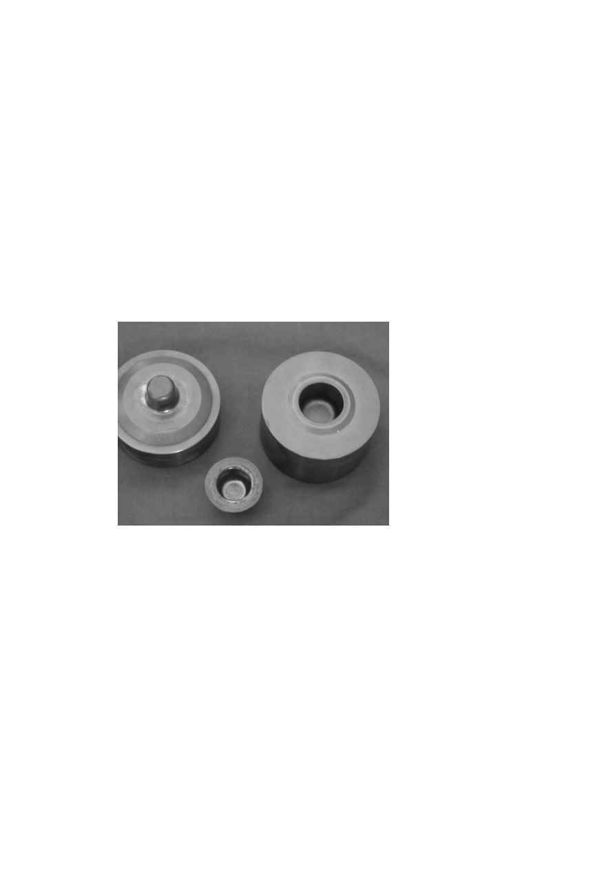
A rotary cup-shaped workpiece with flash was selected as the forging
part. The upper tool was fitted with a mandrel with a 10° draft angle, the
lower tool without ejector had a draft angle of 5°. Typical wear locations
were defined on the mandrel head radius, R = 5 mm on the male die, and
the flash edge radius, R = 1 mm at the female die.
Figure 1 shows the male die, a forged part and the female die.
Figure 1.
Male die, forged workpiece, female die (from the left to the right).

Practical Tests of Coated Hot Forging Dies
155
The test plan included the following parameters:
-Coupling spindle press
Eumuco SPKA2000, 20.000 kN
forging force
-Heating up of the samples
in a batch-type furnace
(electrically heated)
-Furnace temperature
1.120
◦
C
-Sample material
16MnCr
5
-Lubricant
Hycogen 87/13H (Fuchs Lubritec GmbH, FRG)
-Die coatings
coating of both upper and lower tool
-Variant №0
uncoated
-Variant №1
Titanium-aluminium nitride coating (2.8 µm)
-Variant №2
Chromium disilicide coating (1.6 µm)
-Variant №3
TMS coating (3.0 µm)
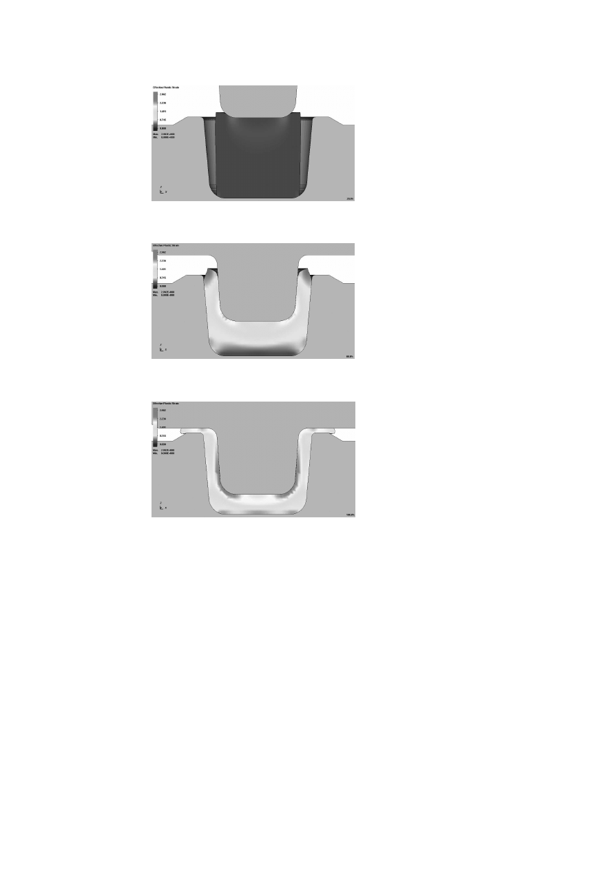
The shaping procedure during forging was subject to FE analysis (see Annex
1). In this simulation, the locations of maximal deformation were forecasted
and thus the worst-case wear positions were defined.
Maximal wear was found on the male die on the mandrel head radius
including the transition area to the mandrel wall (to different lengths), as
well as on the lower tool in the region of the flash edge radius and on the
bottom radius. In the following discussion, the evaluations are related to
these wear locations.
The male die surface temperature after forging, in the case of adhering
parts, is considerable. The male die surface temperature is the result of
the heat transfer during the up to 10 seconds of the adherence of the part
to the mandrel. Immediately after removing the part by means of a tong,
surface temperatures of up to 430
◦
C , which dropped down to 120
◦
C after
60 seconds, were measured.

156
6TH INTERNATIONAL TOOLING CONFERENCE
EVALUATION OF THE COATINGS IN FORGING TESTS
The forging part’s easy separation from the mandrel was selected as the
subjective feature to represent the behaviour of the coatings during forging.
This criterion is extremely important for a continuous forging procedure.
In the tests, TMS coating provided the best results. All parts separated on
their own without outside influence. It was even possible to forge without
adding lubricant, which can be traced back to the effect of the carbon partially
bound in the coating like graphite. For the CrSi
2
-coating, an increased
friction could be detected during forging. It is assumed that the crystalline
structure of this coating is the reason for this behaviour. As a result, about
70% of the parts continued to adhere to the mandrel in the upper tool. This
percentage even exceeded that of the uncoated tool. When the commonly
used hard material coating TiAlN was applied, about 20% of the forging
parts adhered to the mandrel.
INDUSTRIAL TEST OF CVD-COATED FORGING DIES
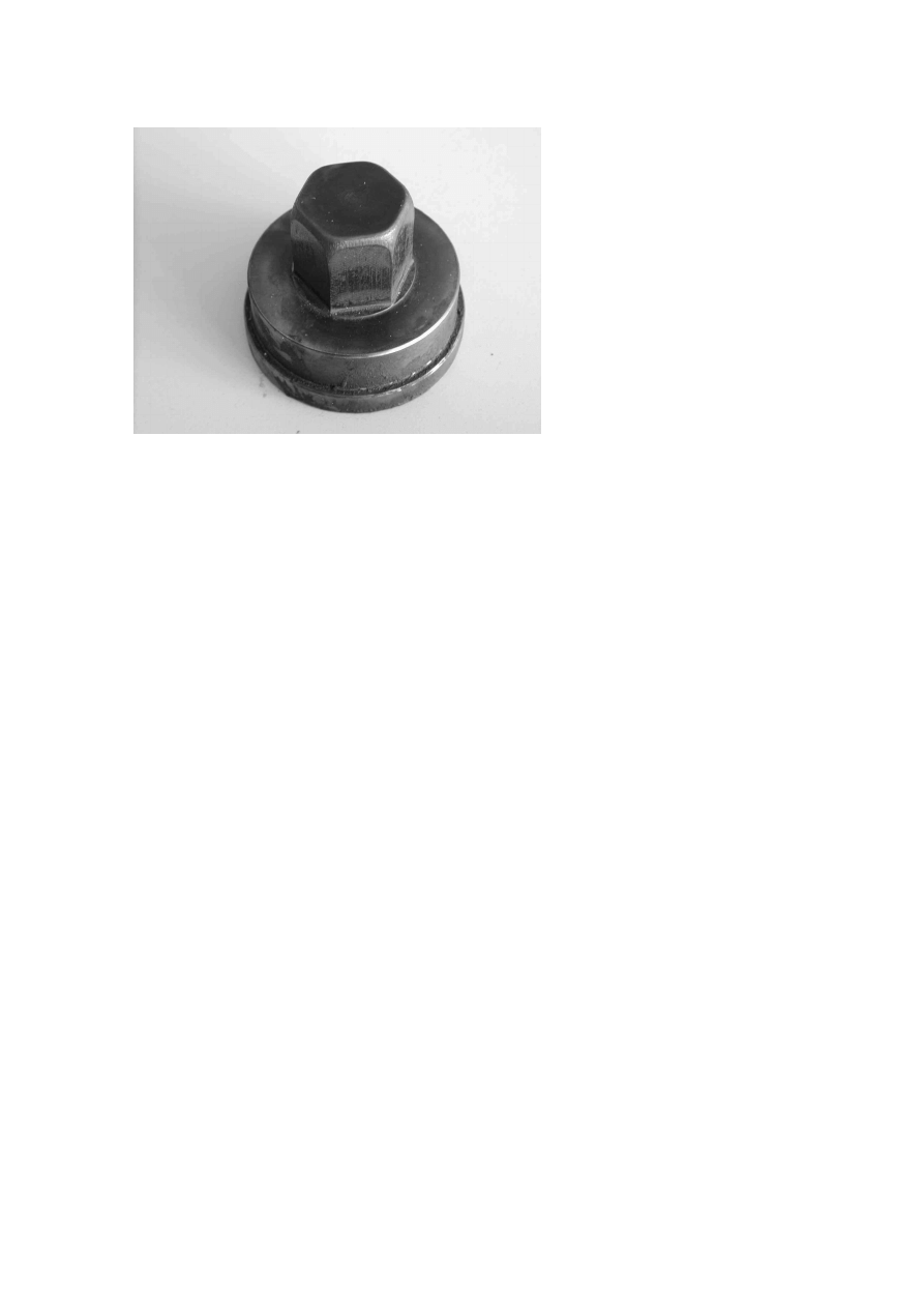
Three coating variants were tested and evaluated (see Fig. 2 and [3]) under
test conditions close to industrial conditions. During real use in a forging
plant, the tools have to withstand higher stresses due to longer-period thermal
influences. An industrial forging part, a hexagon socket screw with 24 mm
nut across flats, was taken as test sample. In contrast to the cylindrical body
of the first test part, this part required the use of a non-rotary mandrel with
several edges and surfaces (see Fig. 2).
The wear criterion for a tool change was determined by the dimensional
accuracy of the hexagon socket contour which was checked with a reference
gauge.
If particles of the forging part’s material (X 5 Cr Ni 13 4) adhere to the
upper tool (material X 32 Cr Mo V 3 3) during forging, then the size of
the hexagon socket is increased and the wear criterion is reached within a
short time. With each follow-up forging operation, new particles continue
to adhere to the upper tool’s surfaces and intensify this effect. Accordingly,
the coating has to meet the requirements resulting from high temperatures,
high surface pressures, and relative motions between tool- and forging part
materials.
The real forging dies were coated with thermally activated CVD at about
1000
◦
C and afterwards hardened in vacuum. The obtained coating was a
Practical Tests of Coated Hot Forging Dies
157
Figure 2.
Coated upper die of an industrial forging tool (Sternberg Comp.)
multilayer coating of the composition TiC / TiCN / TiN (from inside to
outside), thus it was not a silicide coating. The total coating thickness was
about 4 µm.
Whereas the parts adhered at once in the case of uncoated upper tools, at
the coated tools no adherence (so-called weld-ons) occured.
The application of an additional graphite containing lubricant (Hycogen
87/13, Lubritech Fuchs, FRG) sprayed on the tool surfaces resulted, in this
specific application, in an increased tool life.
ANNEX 1
FEM ANALYSIS OF THE METAL FLOW DURING FORG-
ING PROCESS
ACKNOWLEDGMENTS
The research work (AiF PROINNO KF 0019505KBV9) was promoted
with funds of the German Federal Ministry of Economy and Technology
through the work group of Industrial Research Organisation "Otto von Gu-
ericke" e. V. (AiF), Berlin.
158
6TH INTERNATIONAL TOOLING CONFERENCE
Figure 3.
Figure 4.
Figure 5.
REFERENCES

Practical Tests of Coated Hot Forging Dies
159
[1] M. BILEK AND W. MILNE, in Thin Solid Films, 290–291 (1996), pp. 299-304.
[2] R. WOLF and F. KUNATH and W. GRIMM and B. WIELAGE and S. STEINH ¨
AUSER
and M. KOLBE, in 4. Werkstofftechnisches Kolloquium, 20/21st September 2001, TU
Chemnitz, Schriftreihe Werkstoffe und werkstofftechnische Anwendungen, Vol. 007,
pp. 54–59.
[3] M. KOLBE and B. LORENZ, in Bericht IWU Chemnitz (not published), 2001.
Wyszukiwarka
Podobne podstrony:
12 12 extra practice LETTER OF COMPLAINT
first certificate practice tests and key 2
A practical grammar of the Latin languag
Proficiency Practice Tests Exam Test 2 3 (2)
8 95 111 Investigation of Friction and Wear Mechanism of Hot Forging Steels
52 737 754 Relationship Between Microstructure and Mechanical Properts of a 5%Cr Hot Works
1 3 16 Comparison of Different Characteristics of Modern Hot Work Tool Steels
SHSBC 247 R2 12 THEORY AND PRACTICE PART I
151 159
Resuscitation Hands on?fibrillation, Theoretical and practical aspects of patient and rescuer safet
SHSBC 248 R2 12 THEORY AND PRACTICE PART II
practice tests COVER
first certificate practice tests and key 2
A practical grammar of the Latin languag
040 Drying of Coated Webs
więcej podobnych podstron