Quidway S9300 Terabit Routing Switch
V100R006C00
Configuration Guide - WAN Access
Issue
02
Date
2011-07-15
HUAWEI TECHNOLOGIES CO., LTD.

Copyright © Huawei Technologies Co., Ltd. 2011. All rights reserved.
No part of this document may be reproduced or transmitted in any form or by any means without prior written
consent of Huawei Technologies Co., Ltd.
Trademarks and Permissions
and other Huawei trademarks are trademarks of Huawei Technologies Co., Ltd.
All other trademarks and trade names mentioned in this document are the property of their respective holders.
Notice
The purchased products, services and features are stipulated by the contract made between Huawei and the
customer. All or part of the products, services and features described in this document may not be within the
purchase scope or the usage scope. Unless otherwise specified in the contract, all statements, information,
and recommendations in this document are provided "AS IS" without warranties, guarantees or representations
of any kind, either express or implied.
The information in this document is subject to change without notice. Every effort has been made in the
preparation of this document to ensure accuracy of the contents, but all statements, information, and
recommendations in this document do not constitute the warranty of any kind, express or implied.
Huawei Technologies Co., Ltd.
Address:
Huawei Industrial Base
Bantian, Longgang
Shenzhen 518129
People's Republic of China
Website:
Email:
support@huawei.com
Issue 02 (2011-07-15)
Huawei Proprietary and Confidential
Copyright © Huawei Technologies Co., Ltd.
i
About This Document
Intended Audience
This document provides the basic concepts, configuration procedures, and configuration
examples in different application scenarios of the wide area network (WAN) access features
supported by the S9300.
This document describes how to configure the WAN access features.
NOTE
To use the WAN card, ensure that a clock subcard is installed on the SRU.
This document is intended for:
l
Data configuration engineers
l
Commissioning engineers
l
Network monitoring engineers
l
System maintenance engineers
Symbol Conventions
The symbols that may be found in this document are defined as follows.
Symbol
Description
DANGER
Indicates a hazard with a high level of risk, which if not
avoided, will result in death or serious injury.
WARNING
Indicates a hazard with a medium or low level of risk, which
if not avoided, could result in minor or moderate injury.
CAUTION
Indicates a potentially hazardous situation, which if not
avoided, could result in equipment damage, data loss,
performance degradation, or unexpected results.
TIP
Indicates a tip that may help you solve a problem or save
time.
Quidway S9300 Terabit Routing Switch
Configuration Guide - WAN Access
About This Document
Issue 02 (2011-07-15)
Huawei Proprietary and Confidential
Copyright © Huawei Technologies Co., Ltd.
ii
Symbol
Description
NOTE
Provides additional information to emphasize or supplement
important points of the main text.
Command Conventions
The command conventions that may be found in this document are defined as follows.
Convention
Description
Boldface
The keywords of a command line are in boldface.
Italic
Command arguments are in italics.
[ ]
Items (keywords or arguments) in brackets [ ] are optional.
{ x | y | ... }
Optional items are grouped in braces and separated by
vertical bars. One item is selected.
[ x | y | ... ]
Optional items are grouped in brackets and separated by
vertical bars. One item is selected or no item is selected.
{ x | y | ... }
*
Optional items are grouped in braces and separated by
vertical bars. A minimum of one item or a maximum of all
items can be selected.
[ x | y | ... ]
*
Optional items are grouped in brackets and separated by
vertical bars. Several items or no item can be selected.
&<1-n>
The parameter before the & sign can be repeated 1 to n times.
#
A line starting with the # sign is comments.
Change History
Updates between document issues are cumulative. Therefore, the latest document issue contains
all updates made in previous issues.
Changes in Issue 02 (2011-07-15)
The second commercial release has the following updates:
The following contents are modified:
l
1.3.4 Configuring Overhead Bytes
l
2.4.2 Configuring a Local Device to Authenticate Its Peer in PAP Mode
l
2.5.2 Configuring a Local Device with a User Name to Authenticate Its Peer in CHAP
Mode
Quidway S9300 Terabit Routing Switch
Configuration Guide - WAN Access
About This Document
Issue 02 (2011-07-15)
Huawei Proprietary and Confidential
Copyright © Huawei Technologies Co., Ltd.
iii

Changes in Issue 01 (2011-05-20)
Initial commercial release.
Quidway S9300 Terabit Routing Switch
Configuration Guide - WAN Access
About This Document
Issue 02 (2011-07-15)
Huawei Proprietary and Confidential
Copyright © Huawei Technologies Co., Ltd.
iv

Contents
1.1 Overview of POS and CPOS Interfaces.............................................................................................................2
1.2 POS Interface Features Supported by the S9300................................................................................................5
1.3 Configuring POS Interfaces................................................................................................................................5
1.3.1 Establishing the Configuration Task.........................................................................................................5
1.3.2 Configuring the Link-Layer Protocol on the POS Interface......................................................................6
1.3.3 Configuring Clock Mode...........................................................................................................................6
1.3.4 Configuring Overhead Bytes.....................................................................................................................7
1.3.5 Configuring Frame Format........................................................................................................................8
1.3.6 Configuring the Scramble Function..........................................................................................................8
1.3.7 Configuring the Length of the CRC Check Character..............................................................................9
1.3.8 Configuring MTU......................................................................................................................................9
1.3.9 Setting Alarm Thresholds on a POS Interface.........................................................................................10
1.3.10 Checking the Configuration...................................................................................................................11
1.4.1 Enabling Loopback Detection on an Interface........................................................................................12
1.4.2 Clearing the Interface Statistics...............................................................................................................13
2.3.1 Establishing the Configuration Task.......................................................................................................17
2.3.2 Encapsulating the Interface with PPP......................................................................................................18
2.3.3 Configuring the Timeout Period of Negotiation......................................................................................19
2.3.4 Configuring the Polling Interval..............................................................................................................19
2.3.5 Preventing the Peer Host Route from Being Added to the Local Routing Table of Direct Routes........19
2.3.6 Checking the Configuration.....................................................................................................................20
Quidway S9300 Terabit Routing Switch
Configuration Guide - WAN Access
Contents
Issue 02 (2011-07-15)
Huawei Proprietary and Confidential
Copyright © Huawei Technologies Co., Ltd.
v

2.4.2 Configuring a Local Device to Authenticate Its Peer in PAP Mode.......................................................22
2.4.3 Configuring the Peer to Be Authenticated by the Local Device in PAP Mode.......................................23
2.4.4 Checking the Configuration.....................................................................................................................24
2.5.1 Establishing the Configuration Task.......................................................................................................25
2.5.2 Configuring a Local Device with a User Name to Authenticate Its Peer in CHAP Mode......................26
2.5.3 Configuring a Local Device Without a User Name to Authenticate Its Peer in CHAP Mode................27
2.5.4 Checking the Configuration.....................................................................................................................29
2.6.1 Example for Configuring PAP Authentication........................................................................................30
2.6.2 Example for Configuring Unidirectional CHAP Authentication............................................................32
2.6.3 Example for Configuring Bidirectional CHAP Authentication..............................................................35
3.3.1 Establishing the Configuration Task.......................................................................................................40
3.3.2 Encapsulating an Interface with HDLC...................................................................................................41
3.3.3 Configuring the IP Address of the Interface............................................................................................41
3.3.4 Setting the Polling Interval......................................................................................................................42
3.3.5 Checking the Configuration.....................................................................................................................42
3.4.1 Establishing the Configuration Task.......................................................................................................43
3.4.2 Creating an IP-Trunk and Adding Member Interfaces to the IP-Trunk..................................................43
3.4.3 Configuring an IP Address for the IP-Trunk Interface............................................................................45
3.4.4 (Optional) Configuring the Lower Threshold of Up Links.....................................................................46
3.4.5 Checking the Configuration.....................................................................................................................46
3.6.1 Example for Configuring HDLC.............................................................................................................48
3.6.2 Example for Configuring an IP-Trunk....................................................................................................50
Quidway S9300 Terabit Routing Switch
Configuration Guide - WAN Access
Contents
Issue 02 (2011-07-15)
Huawei Proprietary and Confidential
Copyright © Huawei Technologies Co., Ltd.
vi

1
POS Interface Configuration
About This Chapter
The Packet over SONET/SDH (POS) technology is applied to MAN and WAN.
1.1 Overview of POS and CPOS Interfaces
1.2 POS Interface Features Supported by the S9300
1.3 Configuring POS Interfaces
1.4 Maintaining POS Interface Configuration
Quidway S9300 Terabit Routing Switch
Configuration Guide - WAN Access
1 POS Interface Configuration
Issue 02 (2011-07-15)
Huawei Proprietary and Confidential
Copyright © Huawei Technologies Co., Ltd.
1

1.1 Overview of POS and CPOS Interfaces
This section describes concepts of SONET and SDH, channelization and non-channelization,
and frame structure of SDH.
Introduction to SONET and SDH
Synchronous Optical Network (SONET) is the synchronous digital transmission standard
defined by the American National Standards Institute (ANSI) and mainly used in North America
and Japan. Clocks at each level in an entire network are provided by a very precise master clock.
SONET defines the line rate hierarchical structure of synchronous transmission for the optical
transmission system. The basic transmission rate of the SONET is 51.84 Mbit/s and
approximately equals the transmission rate of E3/T3.
l
For an electrical signal, the transmission rate is called Level 1 Synchronous Transport
Signal, namely, STS-1.
l
For an optical signal, the transmission rate is called Level 1 Optical Carrier, namely, OC-1.
Adopting synchronous signals, SONET can easily multiplex multiple signals.
Based on SONET, Synchronous Digital Hierarchy (SDH) is an international standard defined
by the ITU-T and mainly used in Europe. The corresponding standard of SDH is the proposals
from G.707 to G.709 passed in 1988 and the proposals added in 1992.
SDH is similar to SONET to a great extent. The basic rate of SDH is 155.52 Mbit/s, which is
called Level 1 Synchronous Transfer Module, STM-1. This rate equals the OC-3 rate in SONET.
Adopting synchronous multiplexing and flexible mapping, SDH can multiplex or demultiplex
low-speed tributary signals from SDH signals without using multiplexing or demultiplexing
devices. This reduces signal consumption and equipment investment.
lists the common transmission rates of SONET and SDH. The hierarchical relationship
between common transmission rates is four times. For convenience, the approximations in the
parentheses are often used to express transmission rates.
Table 1-1 Relationship between common transmission rates of SONET and SDH
SONET
SDH
Transmission Rate
(Mbit/s)
Electrical
Signal
Optical Signal
Optical Signal
STS-1
OC-1
-
51.840
STS-3
OC-3
STM-1
155.520 (155)
STS-9
OC-9
STM-3
466.560
STS-12
OC-12
STM-4
622.080 (622)
STS-18
OC-18
STM-6
933.120
STS-24
OC-24
STM-8
1244.160
Quidway S9300 Terabit Routing Switch
Configuration Guide - WAN Access
1 POS Interface Configuration
Issue 02 (2011-07-15)
Huawei Proprietary and Confidential
Copyright © Huawei Technologies Co., Ltd.
2

SONET
SDH
Transmission Rate
(Mbit/s)
Electrical
Signal
Optical Signal
Optical Signal
STS-36
OC-36
STM-12
1866.240
STS-48
OC-48
STM-16
2488.320 (2.5 Gbit/s)
STS-96
OC-96
STM-32
4876.640
STS-192
OC-192
STM-64
9953.280 (10 Gbit/s)
Channelization and Unchannelization
When SDH signals are formed by multiplexing low-speed tributary signals, these signals are
called channels.
Channelization indicates that multiple independent channels of data are transmitted over an
optical fiber by using low-speed tributary STM-N signals. During the transmission, each channel
has its own bandwidth and start and end points, and follows its own monitoring policy.
Unchannelization indicates that all data is transmitted in a single channel over an optical fiber
by using all STM-N signals. During the transmission, all the data has the same ID and start and
end points, and follows the same monitoring policy.
Channelization can utilize bandwidth in transmitting multiple channels of low-speed signals.
Unchannelization is adopted to transmit a single channel of high-speed signals.
POS
The Packet over SONET/SDH (POS) technology is applied to MAN and WAN, supporting
packet data such as IP packets.
Frame Structure of SDH
To facilitate understanding, the following section describes the frame structure of the SDH
signal, that is, the structure of the STM-N frame.
To add or drop low-speed tributary signals to or from high-speed signals, try to distribute
tributary signals in the frame equably and regularly. The ITU-T regulates that STM-N frames
are rectangular and expressed in bytes, as shown in
.
Quidway S9300 Terabit Routing Switch
Configuration Guide - WAN Access
1 POS Interface Configuration
Issue 02 (2011-07-15)
Huawei Proprietary and Confidential
Copyright © Huawei Technologies Co., Ltd.
3
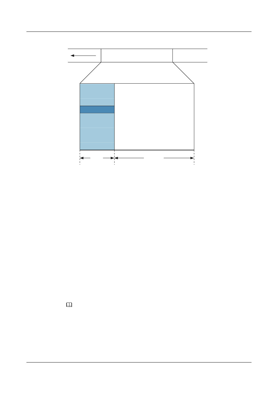
Figure 1-1 STM-N frame structure
Regenerator
Section
Overhead
AUPTR
Multiplex
Section
Overhead
Payload
9*N
261*N
1
2
3
4
5
6
7
8
9
9*270*N(bytes)
STM-N is the frame with the dimension of 9 rows x 270 x N columns. Here, N is consistent with
that in STM-N, indicating how many STM-1 signals are multiplexed to this STM-N signal.
An STM-N frame consists of the following parts:
l
Section Overhead (SOH): includes Regenerator Section Overhead (RSOH) and Multiplex
Section Overhead (MSOH).
l
Administration Unit Pointer (AU-PTR): is the pointer that specifies the first byte of the
payload. The receiving end can correctly extract the payload according to the location of
the pointer.
l
Payload
Overhead Bytes
SDH provides monitoring and management in layers. Monitoring is classified into section
monitoring and path monitoring. Section monitoring is classified into regenerator section
monitoring and multiplex section monitoring. Path monitoring is classified into higher-order
path monitoring and lower-order path monitoring. Different overhead bytes help to implement
the monitoring functions.
NOTE
This section describes only some SDH overhead bytes used in configuration. For details, refer to a book
about the particular topic.
l
SOH
SOH consists of RSOH and MSOH.
The payload of an STM-N frame contains the path overhead (POH) that monitors low-
speed tributary signals.
Quidway S9300 Terabit Routing Switch
Configuration Guide - WAN Access
1 POS Interface Configuration
Issue 02 (2011-07-15)
Huawei Proprietary and Confidential
Copyright © Huawei Technologies Co., Ltd.
4

J0, the regeneration section trace byte is contained in RSOH. This byte is used to transmit
the Section Access Point Identifiers (SAPIs) repeatedly to check the connection between
the receiver and the transmitter. The byte can be any character in the networks of a carrier,
whereas the J0 byte of the receiver and the transmitter must match each other at the border
of networks between two carriers. With the JO byte, a carrier can locate and rectify faults
in advance to speed up the network recovery.
l
Path overhead
SOH monitors section layers, whereas POH monitors path layers. POH is classified into
lower-order path overhead and higher-order path overhead.
The higher-order path overhead monitors the paths at VC-4 and VC-3 levels.
J1, the higher-order VC-N path trace byte, is contained in the higher-order path overhead.
Similar to j0, J1 is used to transmit SAPIs repeatedly to check the connection between the
receiver and the transmitter. J1 bytes of the receiver and transmitter must match each other.
C2, the path signal label byte, is contained in higher-order path overhead. C2 is used to
specify the multiplexing structure and the attributes of the information payload in a VC
frame, including whether the path is loaded with services, service types, and the mapping
mode. C2 bytes of the receiver and transmitter must match each other.
1.2 POS Interface Features Supported by the S9300
Packet over SONET/SDH (POS) maps packets of variable lengths into the payload of SONET/
SDH signals. POS transmits packets at the physical layer of SONET/SDH, which provides a
high speed, reliable, and point-to-point data connection.
The S9300 supports the configurations of link-layer protocols, clock mode, overhead byte, and
CRC check on POS interfaces.
1.3 Configuring POS Interfaces
You can configure the link layer protocol, clock mode, overhead byte, frame format, and CRC
for POS interfaces.
1.3.1 Establishing the Configuration Task
Before configuring POS interfaces, familiarize yourself with the applicable environment,
complete the pre-configuration tasks, and obtain the required data. This can help you complete
the configuration task quickly and accurately.
Applicable Environment
Before using a SONET/SDH optical interface to bear packet data, you need to configure
parameters for the POS interface.
Pre-configuration Tasks
Before configuring a POS interface, complete the following task:
l
Powering on the switch and starting it normally
Quidway S9300 Terabit Routing Switch
Configuration Guide - WAN Access
1 POS Interface Configuration
Issue 02 (2011-07-15)
Huawei Proprietary and Confidential
Copyright © Huawei Technologies Co., Ltd.
5

Data Preparation
To configure a POS interface, you need the following data.
No.
Data
1
Number of the POS interface on the switch
2
Link layer protocol of the POS interface
3
Clock mode of the POS interface
4
Values of overload bytes C2, J0, and J1
5
Frame format of the POS interface
6
Length of the CRC check character
7
MTU of the POS interface
8
Alarm threshold of the POS interface
1.3.2 Configuring the Link-Layer Protocol on the POS Interface
The link-layer protocol on the POS interface can be PPP or HDLC.
Procedure
Step 1 Run:
system-view
The system view is displayed.
Step 2 Run:
interface pos interface-number
The POS interface view is displayed.
Step 3 Run:
link-protocol { ppp | hdlc }
The link-layer protocol is configured for the POS interface.
By default, the POS interface uses the Point-to-Point Protocol (PPP) as the link-layer protocol.
----End
1.3.3 Configuring Clock Mode
A POS interface works in either master clock mode or slave clock mode. You need to configure
different clock modes for POS interfaces that function as the DTE device and the DCE device.
Context
A POS interface supports the following clock modes:
l
Master clock mode: uses internal clock signal.
Quidway S9300 Terabit Routing Switch
Configuration Guide - WAN Access
1 POS Interface Configuration
Issue 02 (2011-07-15)
Huawei Proprietary and Confidential
Copyright © Huawei Technologies Co., Ltd.
6

l
Slave clock mode: uses line clock signal.
Similar to a synchronous serial interface working in DTE and DCE modes, a POS also works
in different clock modes.
l
When the POS interfaces of two switches are connected directly or through the Wavelength
Division Multiplexing (WDM) device, configure one interface to work in master clock
mode and the other interface in slave clock mode to avoid link flapping.
l
When the POS interface of a switch, which functions as a DTE, is connected to a switching
device that functions as a DCE and uses internal clock signals, configure the POS interface
to work in slave clock mode.
Procedure
Step 1 Run:
system-view
The system view is displayed.
Step 2 Run:
interface pos interface-number
The POS interface view is displayed.
Step 3 Run:
clock { master | slave }
Clock mode of the POS interface is configured.
By default, a POS interface works in master clock mode.
----End
1.3.4 Configuring Overhead Bytes
SONET/SDH provides a variety of overhead bytes to implement monitoring at different levels.
Context
C2, the path signal label byte, is contained in the higher-order path overhead. C2 is used to
specify the multiplexing structure and the attributes of the information payload in a VC frame.
J0, the regeneration section trace byte, is contained in the section overhead. It is used to detect
the continuity of the connection between two ports on the section layer.
J1, the higher-order VC-N path trace byte, is used to detect the connectivity of the connection
between two ports on the path layer.
C2, J0, and J1 of the receiver and the transmitter must be the same; otherwise, the two ends
cannot communicate.
Procedure
Step 1 Run:
system-view
The system view is displayed.
Quidway S9300 Terabit Routing Switch
Configuration Guide - WAN Access
1 POS Interface Configuration
Issue 02 (2011-07-15)
Huawei Proprietary and Confidential
Copyright © Huawei Technologies Co., Ltd.
7

Step 2 Run:
interface pos interface-number
The POS interface view is displayed.
Step 3 Run:
flag c2 c2–value
flag j0 { 1byte-mode value | 16byte-mode value | 64byte-or-null-mode value | peer }
flag j1 { 1byte-mode value | 16byte-mode value | 64byte-or-null-mode value | peer }
Overhead bytes of the POS interface are configured.
----End
1.3.5 Configuring Frame Format
The frame format of an interface determines the application mode of the interface. POS interfaces
support two frame formats, namely, SDH and SONET.
Context
A POS interface supports the following types of frame formats:
l
SDH
l
SONET
Procedure
Step 1 Run:
system-view
The system view is displayed.
Step 2 Run:
interface pos interface-number
The POS interface view is displayed.
Step 3 Run:
frame-format { sdh | sonet }
Frame format of the POS interface is configured.
By default, the frame format of a POS interface is SDH.
----End
1.3.6 Configuring the Scramble Function
POS interfaces support the scrambling function for the payload data to avoid excessive number
of consecutive 1s or 0s and help the receiver extract line clock signals.
Context
The scrambling function of the directly connected interfaces must be configured the same.
Quidway S9300 Terabit Routing Switch
Configuration Guide - WAN Access
1 POS Interface Configuration
Issue 02 (2011-07-15)
Huawei Proprietary and Confidential
Copyright © Huawei Technologies Co., Ltd.
8

Procedure
Step 1 Run:
system-view
The system view is displayed.
Step 2 Run:
interface pos interface-number
The POS interface view is displayed.
Step 3 Run:
scramble
The scrambling function of the payload is configured for the POS interface.
By default, the scrambling function is enabled on the payload.
----End
1.3.7 Configuring the Length of the CRC Check Character
POS interfaces support the CRC character in either 16 bits or 32 bits.
Procedure
Step 1 Run:
system-view
The system view is displayed.
Step 2 Run:
interface pos interface-number
The POS interface view is displayed.
Step 3 Run:
crc { 16 | 32}
The length of the CRC check character is configured for the POS interface.
By default, 32-bit CRC is adopted.
----End
1.3.8 Configuring MTU
The MTU is used to assemble and disassemble packets on a POS interface when packets are
sent and received on the interface through the IP network protocol.
Context
A switch reassembles and fragments the sent and received packets according to the MTU.
Quidway S9300 Terabit Routing Switch
Configuration Guide - WAN Access
1 POS Interface Configuration
Issue 02 (2011-07-15)
Huawei Proprietary and Confidential
Copyright © Huawei Technologies Co., Ltd.
9

CAUTION
After changing the MTU of the interface by running the mtu command, restart the interface to
validate the configuration by running the shutdown and undo shutdown commands
consecutively.
Procedure
l
Configuring IPv4 MTU
1.
Run:
system-view
The system view is displayed.
2.
Run:
interface pos interface-number
The POS interface view is displayed.
3.
Run:
mtu mtu
The IPv4 MTU of the POS interface is configured.
The MTU is expressed in bytes, and its value ranges from 46 to 9600. By default, the
MTU is 4470 bytes.
l
Configuring IPv6 MTU
1.
Run:
system-view
The system view is displayed.
2.
Run:
interface pos interface-number
The POS interface view is displayed.
3.
Run:
ipv6 mtu mtu
The IPv6 MTU of the POS interface is configured.
The MTU is expressed in bytes, and its value range from 1280 to 9660. By default,
the MTU is 4470 bytes.
CAUTION
After configuring the IPv6 MTU, run the ppp mru-negotiate ipv6 command to start
negotiation of the IPv6 MTU.
----End
1.3.9 Setting Alarm Thresholds on a POS Interface
The alarm thresholds on a POS interface help you monitor link performance.
Quidway S9300 Terabit Routing Switch
Configuration Guide - WAN Access
1 POS Interface Configuration
Issue 02 (2011-07-15)
Huawei Proprietary and Confidential
Copyright © Huawei Technologies Co., Ltd.
10

Context
When link performance deteriorates, set the alarm thresholds on POS interfaces to learn link
status.
The SD alarm indicates that signal deteriorates and SF indicates a signal failure. The SF alarm
is severer than the SD alarm. The SD or SF alarm is generated when the receiver detects a B2
error. The bit error rates that trigger the SF alarm and SD alarm are different. When a few bit
errors occur, an SD alarm is generated; when the number of bit errors increases to the certain
limit, an SF alarm is generated, indicating that the link quality deteriorates.
Procedure
Step 1 Run:
system-view
The system view is displayed.
Step 2 Run:
interface pos interface-number
The POS interface view is displayed.
Step 3 Run:
threshold { sd | sf } value
The alarm thresholds are set on the POS interface.
The default SD alarm threshold is 6 and the default SF alarm threshold is 3.
----End
1.3.10 Checking the Configuration
After configuring POS interfaces, you can view the configuration and status of POS interfaces.
Prerequisite
The configurations of the POS interfaces are complete.
Procedure
l
Run the display interface pos [ interface-number ] command to check the configuration
and status of the POS interface.
l
Run the display interface brief command to check brief information about the POS
interface.
----End
Example
After running the display interface brief command, you can check brief information about the
physical status, link layer protocol status, bandwidth utilization, and number of incorrect packets
of the POS interface. The display of the command is as follows:
<Quidway> display interface brief | include Pos
*down: administratively down
^down: standby
Quidway S9300 Terabit Routing Switch
Configuration Guide - WAN Access
1 POS Interface Configuration
Issue 02 (2011-07-15)
Huawei Proprietary and Confidential
Copyright © Huawei Technologies Co., Ltd.
11

(l): loopback
(s): spoofing
(b): BFD down
(e): ETHOAM down
(d): DampeningSuppressed
InUti/OutUti: input utility/output utility
Interface Physical Protocol InUti OutUti inErrors outErrors
Pos1/0/0 down down 0% 0% 831745956
0
Pos1/0/0 up up 0.01% 0.01%3795064053
0
Pos1/0/1 down down 0% 0% 343911292
0
Pos1/0/2 down down 0% 0% 343913408
0
Pos1/0/3 down down 0% 0% 343915353 0
1.4 Maintaining POS Interface Configuration
You can enable the loopback function to detect whether an interface runs properly and clear
interface statistics to maintain the POS interface.
1.4.1 Enabling Loopback Detection on an Interface
You can enable the loopback function to monitor link status.
Context
CAUTION
After the loopback function is enabled on an interface by using the loopback command, the
interface or link on the interface cannot function properly. Before enabling the loopback
function, ensure that it is necessary. When the loopback function is not required, run the undo
loopback command to disable it.
Procedure
Step 1 Run:
system-view
The system view is displayed.
Step 2 Run:
interface pos interface-number
The POS interface view is displayed.
Step 3 Run:
loopback internal
The loopback function is enabled on the interface.
By default, the loopback function is disabled on an interface.
----End
Quidway S9300 Terabit Routing Switch
Configuration Guide - WAN Access
1 POS Interface Configuration
Issue 02 (2011-07-15)
Huawei Proprietary and Confidential
Copyright © Huawei Technologies Co., Ltd.
12
1.4.2 Clearing the Interface Statistics
You can run the reset command to clear interface statistics before recollecting traffic statistics
on the interface.
Context
CAUTION
The interface statistics cannot be restored after you run the reset command to clear it. So, confirm
the action before you use the command.
To reset the interface statistics of those displayed by running the display interface command,
run the following commands in the user view. Clear the interface statistics before collecting the
traffic.
Procedure
l
Run the reset counters interface [ interface-type [ interface-number ] ] command to clear
the interface statistics displayed by running the display interface command.
----End
1.5 Configuration Examples
This section describes details about POS interfaces, including applicable scenarios and
configuration commands.
1.5.1 Example for Directly Connecting Devices Through POS
Interfaces
This example shows how to connect two devices through POS interfaces in typical networking.
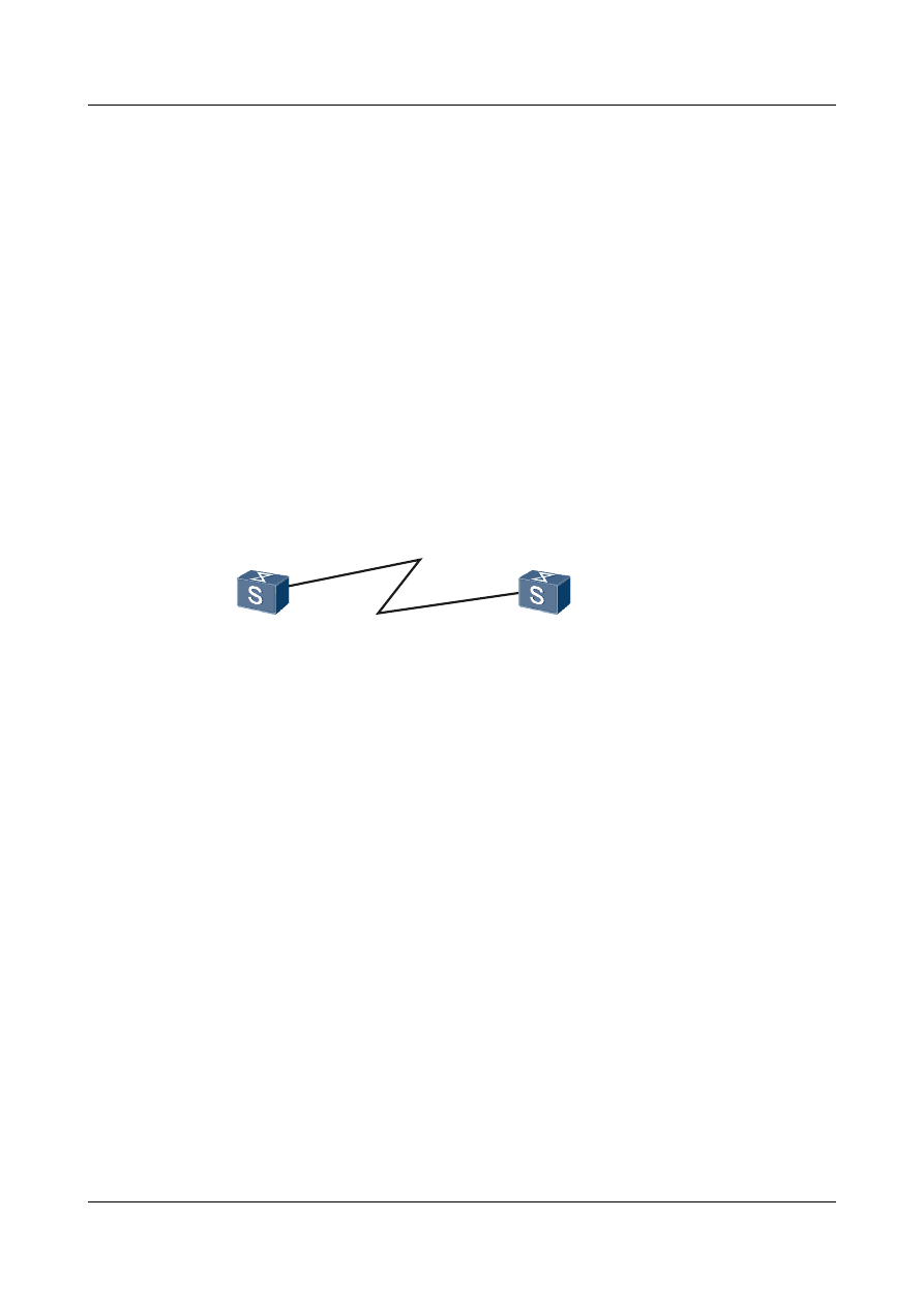
Networking Requirements
As shown in
, POS interfaces on Switch A and Switch B are directly connected with
a pair of single-mode fibers for receiving and sending packets; HDLC is the link layer protocol.
It is required that Switch A and Switch B can communicate.
Figure 1-2 Networking diagram of connecting devices directly through POS interfaces
POS1/0/0
10.1.1.1/30
POS1/0/0
10.1.1.2/30
Switch A
Switch B
Quidway S9300 Terabit Routing Switch
Configuration Guide - WAN Access
1 POS Interface Configuration
Issue 02 (2011-07-15)
Huawei Proprietary and Confidential
Copyright © Huawei Technologies Co., Ltd.
13

Configuration Roadmap
The configuration roadmap is as follows:
1.
Configure HDLC as the link layer protocol.
2.
Configure IP addresses.
Data Preparation
To complete the configuration, you need the following data:
l
IP address of POS 1/0/0 on Switch A
l
IP address of POS 1/0/0 on Switch B
Procedure
Step 1 Configure Switch A.
# Configure POS 1/0/0, set HDLC as the link layer protocol, and set default values for all physical
parameters.
<Quidway> system-view
[Quidway] sysname SwitchA
[SwitchA] interface pos 1/0/0
[SwitchA-Pos1/0/0] link-protocol hdlc
[SwitchA-Pos1/0/0] ip address 10.1.1.1 30
[SwitchA-Pos1/0/0] quit
Step 2 Configure Switch B.
# Configure POS 1/0/0, set the clock mode to slave, and set default values for other physical
parameters.
<Quidway> system-view
[Quidway] sysname SwitchB
[SwitchB] interface pos 1/0/0
[SwitchB-Pos1/0/0] clock slave
[SwitchB-Pos1/0/0] link-protocol hdlc
[SwitchB-Pos1/0/0] ip address 10.1.1.2 30
[SwitchB-Pos1/0/0] quit
Step 3 Verify the configuration.
Run the display interface pos command to check the connectivity of the POS interface on
Switch A.
<SwitchA> display interface pos 1/0/0
Pos1/0/0 current state : UP
Line protocol current state : UP
Last line protocol up time : 2011-01-11 16:58:21
Description:HUAWEI, Quidway Series, Pos1/0/0 Interface
Route Port,The Maximum Transmit Unit is 4470, Hold timer is 10(sec)
Internet Address is 10.1.1.1/30
Link layer protocol is nonstandard HDLC
Physical layer is Packet Over SDH
Clock: Master, Scramble, Loopback: none, CRC: 32
Threshold: SD 10e-6, SF 10e-3
Flag: J0 "NetEngine "
Flag: J1 "NetEngine "
Flag: C2 0x16
SDH error:
section layer: B1 0
line layer: B2 0
Quidway S9300 Terabit Routing Switch
Configuration Guide - WAN Access
1 POS Interface Configuration
Issue 02 (2011-07-15)
Huawei Proprietary and Confidential
Copyright © Huawei Technologies Co., Ltd.
14

path layer: B3 0
Last 600 seconds input rate 88 bits/sec, 0 packets/sec
Last 600 seconds output rate 32 bits/sec, 0 packets/sec
Input peak rate 15880 bits/sec,Record time: 2011-01-11 17:11:03
Output peak rate 1760 bits/sec,Record time: 2011-01-11 17:04:32
Input: 85 packets, 6781 bytes
Input error: 0 shortpacket, 0 longpacket, 2 CRC, 0 lostpacket
Output: 83 packets, 3872 bytes
Output error: 0 lostpacket
Input bandwidth utilization : 0.01%
Output bandwidth utilization : 0.01%
Run the ping command to check the network connectivity.
[SwitchA] ping 10.1.1.2
PING 10.1.1.2: 56 data bytes, press CTRL_C to break
Reply from 10.1.1.2: bytes=56 Sequence=1 ttl=255 time=3 ms
Reply from 10.1.1.2: bytes=56 Sequence=2 ttl=255 time=2 ms
Reply from 10.1.1.2: bytes=56 Sequence=3 ttl=255 time=2 ms
Reply from 10.1.1.2: bytes=56 Sequence=4 ttl=255 time=2 ms
Reply from 10.1.1.2: bytes=56 Sequence=5 ttl=255 time=2 ms
--- 10.1.1.2 ping statistics ---
5 packet(s) transmitted
5 packet(s) received
0.00% packet loss
round-trip min/avg/max = 2/2/3 ms
----End
Configuration Files
l
Configuration file of Switch A
#
sysname SwitchA
#
interface Pos1/0/0
link-protocol hdlc
ip address 10.1.1.1 255.255.255.252
#
return
l
Configuration file of Switch B
#
sysname SwitchB
#
interface Pos1/0/0
link-protocol hdlc
ip address 10.1.1.2 255.255.255.252
clock slave
#
return
Quidway S9300 Terabit Routing Switch
Configuration Guide - WAN Access
1 POS Interface Configuration
Issue 02 (2011-07-15)
Huawei Proprietary and Confidential
Copyright © Huawei Technologies Co., Ltd.
15

2
PPP Configuration
About This Chapter
Functioning at the data link layer of the Open Systems Interconnection (OSI) and the link layer
of the TCP/IP protocol suite, the Point-to-Point Protocol (PPP) is a link layer protocol that is
transmits network layer packets over point-to-point (P2P) links. PPP is developed based on the
Serial Line Internet Protocol (SLIP).
2.2 PPP Features Supported by the S9300
A PPP link is set up by using PAP or CHAP authentication.
2.4 Configuring Unidirectional PAP
2.5 Configuring Unidirectional CHAP
Quidway S9300 Terabit Routing Switch
Configuration Guide - WAN Access
2 PPP Configuration
Issue 02 (2011-07-15)
Huawei Proprietary and Confidential
Copyright © Huawei Technologies Co., Ltd.
16

2.1 PPP Overview
The PPP protocol consists of the Link Control Protocol (LCP), Network Control Protocol (NCP),
and PPP extension protocols. PPP establishes links through a series of negotiations.
A point-to-point (P2P) connection is a simple WAN connection. Link layer protocols of a PPP
link are as follows:
l
Point-to-Point Protocol (PPP): supports synchronous and asynchronous transmission.
l
High-level Data Link Control protocol (HDLC): supports only synchronous transmission.
Located at the data link layer of the Open Systems Interconnection (OSI), PPP supports
synchronous or asynchronous full-duplex links to transmit data from point to point. PPP is widely
used because:
l
It provides user authentication.
l
It supports synchronous and asynchronous communications.
l
It can be easily expanded.
PPP defines a set of protocols, including:
l
Link Control Protocol (LCP): is used to establish, monitor, and terminate data links.
l
Network Control Protocol (NCP): is used to establish and configure different network-layer
protocols, and negotiate the format and type of packets transmitted over data links.
l
Authentication protocols: include Password Authentication Protocol (PAP) and Challenge-
Handshake Authentication Protocol (CHAP), which are used for network security
authentication.
2.2 PPP Features Supported by the S9300
A PPP link is set up by using PAP or CHAP authentication.
PPP can be configured on POS interfaces of the S9300 to implement the following functions:
l
PAP or CHAP authentication
l
PPP negotiation timeout
l
PPP polling interval
l
Suppression of direct route learning
2.3 Setting PPP Parameters
This section describes how to configure PPP as the encapsulation protocol on an interface and
set PPP parameters, including negotiation timeout interval, polling interval, and suppression of
direct route learning.
2.3.1 Establishing the Configuration Task
Before configuring the PPP protocol on an interface, familiarize yourself with the applicable
environment, complete the pre-configuration tasks, and obtain the data required for the
configuration. This will help you complete the configuration task quickly and accurately.
Quidway S9300 Terabit Routing Switch
Configuration Guide - WAN Access
2 PPP Configuration
Issue 02 (2011-07-15)
Huawei Proprietary and Confidential
Copyright © Huawei Technologies Co., Ltd.
17

Applicable Environment
PPP is a link layer protocol that is used to transmit data over P2P links. If MTUs are configured
on the two ends of a link, enable PPP MTU negotiation on the two ends to negotiate the MTU
for data exchange. The MTUs on the two ends must be identical.
Pre-configuration Tasks
Before configuring the PPP protocol, complete the following task:
l
Connecting interfaces and setting physical parameters of the interfaces so that the physical
layer of the interfaces goes Up
Data Preparation
To configure the PPP protocol, you need the following data.
No.
Data
1
Number of the interface
2
PPP negotiation timeout
3
Polling interval
2.3.2 Encapsulating the Interface with PPP
This section describes how to configure PPP as the link layer protocol on an interface.
Context
Do as follows on the switch.
Procedure
Step 1 Run:
system-view
The system view is displayed.
Step 2 Run:
interface interface-type interface-number
The interface view is displayed.
Step 3 Run:
link-protocol ppp
The link layer protocol is configured as PPP.
By default, the link layer protocol of the POS interface is PPP.
----End
Quidway S9300 Terabit Routing Switch
Configuration Guide - WAN Access
2 PPP Configuration
Issue 02 (2011-07-15)
Huawei Proprietary and Confidential
Copyright © Huawei Technologies Co., Ltd.
18

2.3.3 Configuring the Timeout Period of Negotiation
During PPP negotiation, if the peer does not reply with a response packet before the negotiation
times out, PPP resends the negotiation request packet.
Procedure
Step 1 Run:
system-view
The system view is displayed.
Step 2 Run:
interface interface-type interface-number
The interface view is displayed.
Step 3 Run:
ppp timer negotiate seconds
The timeout period of negotiation is configured on the interface.
By default, the PPP negotiation timeout time is 3 seconds.
----End
2.3.4 Configuring the Polling Interval
This section describes how to configure the interval for sending Keepalive packets to the peer.
Procedure
Step 1 Run:
system-view
The system view is displayed.
Step 2 Run:
interface interface-type interface-number
The interface view is displayed.
Step 3 Run:
timer hold seconds
The polling interval is configured on the interface.
By default, the interval for sending Keepalive messages on a POS interface is 10 seconds.
----End
2.3.5 Preventing the Peer Host Route from Being Added to the Local
Routing Table of Direct Routes
This section describes how to prevent the peer host route from being added to the local routing
table of direct routes. This prevents the situation that one end is configured with an incorrect IP
address, and the other end automatically adds the incorrect peer host route to the local routing
table, which results in advertisement of incorrect routing information on the network.
Quidway S9300 Terabit Routing Switch
Configuration Guide - WAN Access
2 PPP Configuration
Issue 02 (2011-07-15)
Huawei Proprietary and Confidential
Copyright © Huawei Technologies Co., Ltd.
19

Context
The PPP link does not strictly require that the peer route and local route exist at the same network
segment. Two ends of the PPP link at different network segments can communicate. In addition,
the peer host route at a different network segment is automatically added to local routing table
of direct routes.
However, when one end is configured with an incorrect IP address, the other end automatically
adds the incorrect peer host route to the local routing table of direct routes. As a result, the
incorrect routing information is advertised across the network.
With this command, you can decide whether the peer host route is added to the local routing
table of direct routes.
Procedure
Step 1 Run:
system-view
The system view is displayed.
Step 2 Run:
interface interface-type interface-number
The interface view is displayed.
Step 3 Run:
ppp peer hostroute-suppress
The peer host route is prevented from being added to the local routing table of direct routes.
NOTE
After enabling or disabling the function of preventing the peer host route from being added to the local
routing table of direct routes, restart the interface to validate the configuration.
Step 4 Choose one of the following methods to restart the interface.
l Run the shutdown and undo shutdown commands.
l Run the restart command.
----End
2.3.6 Checking the Configuration
After configuring the PPP protocol as the encapsulation protocol and setting the PPP parameters,
check whether the configurations are correct.
Prerequisite
All the configurations of PPP are complete.
Procedure
l
Run the display interface [ interface-type [ interface-number ] ] command to check the
PPP configurations on the interface.
----End
Quidway S9300 Terabit Routing Switch
Configuration Guide - WAN Access
2 PPP Configuration
Issue 02 (2011-07-15)
Huawei Proprietary and Confidential
Copyright © Huawei Technologies Co., Ltd.
20

Example
Run the display interface. The PPP configurations on the interface are displayed, for example:
<Quidway> display interface pos 1/0/0
Pos1/0/0 current state : DOWN
Line protocol current state : DOWN
Description:HUAWEI, Quidway Series, Pos1/0/0 Interface
Route Port,The Maximum Transmit Unit is 4470, Hold timer is 1200(sec)
Internet protocol processing : disabled
Link layer protocol is PPP
LCP initial
Physical layer is Packet Over SONET
Clock: Master, Scramble, Loopback: none, CRC: 32
Threshold: SD 10e-8, SF 10e-3
Flag: J0 "NetEngine "
Flag: J1 "NetEngine "
Flag: C2 0x16
SONET error:
section layer: B1
line layer: B2
path layer: B3
Last 300 seconds input rate 0 bits/sec, 0 packets/sec
Last 300 seconds output rate 0 bits/sec, 0 packets/sec
Input peak rate 0 bits/sec,Record time: -
Output peak rate 0 bits/sec,Record time: -
Input: 0 packets, 0 bytes
Input error: 0 shortpacket, 0 longpacket, 0 CRC, 0 lostpacket
Output: 0 packets, 0 bytes
Output error: 0 lostpacket
Input bandwidth utilization : 0.00%
Output bandwidth utilization : 0.00%
2.4 Configuring Unidirectional PAP
This section describes how to configure unidirectional PAP authentication. Detailed operations
include configuring the local device to authenticate the peer in PAP mode and configuring the
peer to be authenticated by the local device in PAP mode.
2.4.1 Establishing the Configuration Task
Before configuring unidirectional PAP authentication, familiarize yourself with the applicable
environment, complete the pre-configuration tasks, and obtain the required data. This can help
you complete the configuration task quickly and accurately.
Applicable Environment
In PAP authentication, passwords are sent over the link in plain text. The username and password
of the authenticated can be added to the user list of the authenticator in Authentication,
Authorization, and Accounting (AAA) mode or through the Remote Authentication Dial in User
Service (RADIUS) server.
PAP authentication is classified into the following types:
l
Unidirectional authentication: One of two communication parties functions as the
authenticator, while the other as the authenticated.
Quidway S9300 Terabit Routing Switch
Configuration Guide - WAN Access
2 PPP Configuration
Issue 02 (2011-07-15)
Huawei Proprietary and Confidential
Copyright © Huawei Technologies Co., Ltd.
21

l
Bidirectional authentication: Two communication parties function as both the authenticator
and the authenticated.
This section describes how to configure unidirectional PAP authentication.
Pre-configuration Tasks
Before configuring PAP authentication, complete the following tasks:
l
Connecting interfaces and configuring physical attributes for these interfaces to ensure that
the physical layer of the interfaces is Up
l
Configuring PPP as the link layer protocol of interfaces
Data Preparation
To configure PAP authentication, you need the following data.
No.
Data
1
Number of the interface
2
Username and password of the authenticated
2.4.2 Configuring a Local Device to Authenticate Its Peer in PAP
Mode
This section describes how to configure PAP-related parameters for the authenticator. PAP
authentication is a two-way authentication mode, and PAP authentication is implemented only
at the beginning of link establishment.
Context
Do as follows on the switch.
Procedure
Step 1 Run:
system-view
The system view is displayed.
Step 2 Run:
aaa
The AAA view is displayed.
Step 3 Run:
local-user user-name password { simple | cipher } password
The username and password of the authenticated are added to the local user list.
Step 4 Run:
quit
Quidway S9300 Terabit Routing Switch
Configuration Guide - WAN Access
2 PPP Configuration
Issue 02 (2011-07-15)
Huawei Proprietary and Confidential
Copyright © Huawei Technologies Co., Ltd.
22

Return to the system view.
Step 5 Run:
interface interface-type interface-number
The interface view is displayed.
Step 6 Run:
ppp authentication-mode pap
The local end authenticates the peer end using PAP.
Step 7 Run:
restart
The interface is restarted.
NOTE
After changing the username and password, run the restart command, or the shutdown and undo
shutdown commands in the interface view to validate the configuration.
----End
2.4.3 Configuring the Peer to Be Authenticated by the Local Device
in PAP Mode
This section describes how to configure PAP-related attributes for the authenticated user.
Context
Do as follows on the switch.
Procedure
Step 1 Run:
system-view
The system view is displayed.
Step 2 Run:
interface interface-type interface-number
The interface view is displayed.
Step 3 Run:
ppp pap local-user user-name password { cipher | simple } password
The username and password of the local end are configured when the local end is configured to
be authenticated using PAP.
Step 4 Run:
restart
The interface is restarted.
Quidway S9300 Terabit Routing Switch
Configuration Guide - WAN Access
2 PPP Configuration
Issue 02 (2011-07-15)
Huawei Proprietary and Confidential
Copyright © Huawei Technologies Co., Ltd.
23

NOTE
After changing the username and password, use the restart command, or the shutdown and undo
shutdown commands in the interface view to validate the configuration.
----End
2.4.4 Checking the Configuration
After unidirectional PAP authentication is configured, you can view the link status and LCP
running status on the interface.
Prerequisite
The configurations of the unidirectional PAP function are complete.
Procedure
l
Run the display interface [ interface-type [ interface-number ] ] command to check the
link status of the interface and the running status of the LCP.
----End
Example
Run the display interface command. If the LCP status is Opened, it means that the PAP
authentication succeeds. For example:
[SwitchA] display interface pos 1/0/0
Pos1/0/0 current state : UP
Line protocol current state : UP
Last line protocol up time : 2011-01-11 17:35:02
Description:HUAWEI, Quidway Series, Pos1/0/0 Interface
Route Port,The Maximum Transmit Unit is 4470, Hold timer is 10(sec)
Internet Address is 10.110.0.1/24
Link layer protocol is PPP
LCP opened, IPCP opened
Physical layer is Packet Over SDH
Clock: Master, Scramble, Loopback: none, CRC: 32
Threshold: SD 10e-6, SF 10e-3
Flag: J0 "NetEngine "
Flag: J1 "NetEngine "
Flag: C2 0x16
SDH error:
section layer: B1 0
line layer: B2 0
path layer: B3 0
Last 600 seconds input rate 72 bits/sec, 0 packets/sec
Last 600 seconds output rate 64 bits/sec, 0 packets/sec
Input peak rate 4380776 bits/sec,Record time: 2011-01-11 17:34:39
Output peak rate 1760 bits/sec,Record time: 2011-01-11 17:04:32
Input: 11490 packets, 2495499 bytes
Input error: 185 shortpacket, 0 longpacket, 10618 CRC, 5 lostpacket
Output: 445 packets, 20044 bytes
Output error: 0 lostpacket
Input bandwidth utilization : 0.01%
Output bandwidth utilization : 0.01%
Quidway S9300 Terabit Routing Switch
Configuration Guide - WAN Access
2 PPP Configuration
Issue 02 (2011-07-15)
Huawei Proprietary and Confidential
Copyright © Huawei Technologies Co., Ltd.
24

2.5 Configuring Unidirectional CHAP
This section describes how to configure unidirectional CHAP authentication. Detailed
operations include configuring the authenticator with a user name to authenticate the peer in
CHAP mode and configuring the authenticator without a user name to authenticate the peer in
CHAP mode.
2.5.1 Establishing the Configuration Task
Before configuring unidirectional CHAP authentication, familiarize yourself with the applicable
environment, complete the pre-configuration tasks, and obtain the required data. This can help
you complete the configuration task quickly and accurately.
Applicable Environment
In CHAP authentication, passwords are sent over the link in encrypted text. The username and
password of the authenticated can be authenticated in AAA mode or through the RADIUS server
and then added into the user list of the authenticator.
CHAP authentication is classified into the following types:
l
Unidirectional: One of two communication parties functions as the authenticator, while the
other as the authenticated.
l
Bidirectional: Two communication parties function as both the authenticator and the
authenticated.
This section describes how to configure unidirectional CHAP authentication.
Pre-configuration Tasks
Before configuring CHAP authentication, complete the following tasks:
l
Connecting interfaces and configuring physical attributes for these interfaces to ensure that
the physical layer of the interfaces is Up
l
Configuring PPP as the link layer protocol of interfaces
Data Preparation
To configure CHAP authentication, you need the following data.
No.
Data
1
Number of the interface
2
(Optional) Username of the authenticator
3
Username and password of the authenticated
Quidway S9300 Terabit Routing Switch
Configuration Guide - WAN Access
2 PPP Configuration
Issue 02 (2011-07-15)
Huawei Proprietary and Confidential
Copyright © Huawei Technologies Co., Ltd.
25

2.5.2 Configuring a Local Device with a User Name to Authenticate
Its Peer in CHAP Mode
This section describes how to configure the authenticator with a user name to authenticate the
peer in CHAP mode.
Context
NOTE
In CHAP authentication, when configuring the username for the authenticator, ensure that the same
password is configured for the authenticator and the authenticated.
Procedure
l
Configuring the authenticator
1.
Run:
system-view
The system view is displayed.
2.
Run:
aaa
The AAA view is displayed.
3.
Run:
local-user user-name password { simple | cipher } password
The username and password of the authenticated are added to the local user list.
4.
Run:
quit
Return to the system view.
5.
Run:
interface interface-type interface-number
The interface view is displayed.
6.
Run:
ppp authentication-mode chap [ pap ]
The local end authenticates the peer end by using CHAP.
You can run the ppp authentication-mode chap pap command to perform CHAP
negotiation preferentially in LCP negotiation. If the peer end does not support CHAP
authentication, PAP negotiation is performed. If the peer end does not support CHAP
or PAP, the LCP negotiation fails. Either CHAP or PAP is involved in a PPP
negotiation.
7.
Run:
ppp chap user user-name
The local username is configured.
8.
Run:
restart
The interface is restarted.
Quidway S9300 Terabit Routing Switch
Configuration Guide - WAN Access
2 PPP Configuration
Issue 02 (2011-07-15)
Huawei Proprietary and Confidential
Copyright © Huawei Technologies Co., Ltd.
26

NOTE
After changing the username and password, run the restart command, or the shutdown and
undo shutdown commands in the interface view to validate the configuration.
l
Configuring the authenticated
1.
Run:
system-view
The system view is displayed.
2.
Run:
aaa
The AAA view is displayed.
3.
Run:
local-user user-name password { simple | cipher } password
The username and password of the authenticated are added to the local user list.
4.
Run:
quit
Return to the system view.
5.
Run:
interface interface-type interface-number
The interface view is displayed.
6.
Run:
ppp chap user user-name
The local username is configured.
7.
Run:
restart
The interface is restarted.
NOTE
After changing the username and password, run the restart command, or the shutdown and
undo shutdown commands in the interface view to validate the configuration.
----End
2.5.3 Configuring a Local Device Without a User Name to
Authenticate Its Peer in CHAP Mode
This section describes how to configure the authenticator without a user name to authenticate
the peer in CHAP mode.
Procedure
l
Configuring the authenticator
1.
Run:
system-view
The system view is displayed.
2.
Run:
Quidway S9300 Terabit Routing Switch
Configuration Guide - WAN Access
2 PPP Configuration
Issue 02 (2011-07-15)
Huawei Proprietary and Confidential
Copyright © Huawei Technologies Co., Ltd.
27

aaa
The AAA view is displayed.
3.
Run:
local-user user-name password { simple | cipher } password
The username and password of the authenticated are added to the local user list.
4.
Run:
quit
Return to the system view.
5.
Run:
interface interface-type interface-number
The interface view is displayed.
6.
Run:
ppp authentication-mode chap [ pap ]
The local end authenticates the peer end using CHAP.
You can run the ppp authentication-mode chap pap command to perform CHAP
negotiation preferentially in LCP negotiation. If the peer end does not support CHAP
authentication, PAP negotiation is performed. If the peer end does not support CHAP
or PAP, the LCP negotiation fails. Either CHAP or PAP is involved in a PPP
negotiation.
7.
Run:
restart
The interface is restarted.
In authentication, if the username and password of the interface on the peer end are
consistent with the username and password in the local AAA user list, the
authentication succeeds.
l
Configuring the authenticated
1.
Run:
system-view
The system view is displayed.
2.
Run:
interface interface-type interface-number
The interface view is displayed.
3.
Run:
ppp chap user user-name
The local username is configured.
4.
Run:
ppp chap password { cipher | simple } password
The password of the local end is configured, which is used when the local end is
authenticated by the peer end using CHAP.
5.
Run:
restart
The interface is restarted.
Quidway S9300 Terabit Routing Switch
Configuration Guide - WAN Access
2 PPP Configuration
Issue 02 (2011-07-15)
Huawei Proprietary and Confidential
Copyright © Huawei Technologies Co., Ltd.
28

NOTE
After changing the username and password, run the restart command, or the shutdown and
undo shutdown commands in the interface view to validate the configuration.
----End
2.5.4 Checking the Configuration
After unidirectional CHAP authentication is configured, you can view the PPP configuration
and PPP status on the interface.
Prerequisite
The configurations of unidirectional CHAP are complete.
Procedure
l
Run the display interface [ interface-type [ interface-number ] ] command to check the
PPP configuration and the status of the interface.
----End
Example
Run the display interface command. You can view the status of PPP, LCP, and IPCP. If the
status of the LCP and IPCP is opened, it means that CHAP authentication succeeds. For example:
[SwitchA] display interface pos 1/0/0
Pos1/0/0 current state : UP
Line protocol current state : UP
Last line protocol up time : 2011-01-11 17:35:02
Description:HUAWEI, Quidway Series, Pos1/0/0 Interface
Route Port,The Maximum Transmit Unit is 4470, Hold timer is 10(sec)
Internet Address is 10.110.0.1/24
Link layer protocol is PPP
LCP opened, IPCP opened
Physical layer is Packet Over SDH
Clock: Master, Scramble, Loopback: none, CRC: 32
Threshold: SD 10e-6, SF 10e-3
Flag: J0 "NetEngine "
Flag: J1 "NetEngine "
Flag: C2 0x16
SDH error:
section layer: B1 0
line layer: B2 0
path layer: B3 0
Last 600 seconds input rate 72 bits/sec, 0 packets/sec
Last 600 seconds output rate 64 bits/sec, 0 packets/sec
Input peak rate 4380776 bits/sec,Record time: 2011-01-11 17:34:39
Output peak rate 1760 bits/sec,Record time: 2011-01-11 17:04:32
Input: 11490 packets, 2495499 bytes
Input error: 185 shortpacket, 0 longpacket, 10618 CRC, 5 lostpacket
Output: 445 packets, 20044 bytes
Output error: 0 lostpacket
Input bandwidth utilization : 0.01%
Output bandwidth utilization : 0.01%
Quidway S9300 Terabit Routing Switch
Configuration Guide - WAN Access
2 PPP Configuration
Issue 02 (2011-07-15)
Huawei Proprietary and Confidential
Copyright © Huawei Technologies Co., Ltd.
29
2.6 Configuration Examples
This section provides several examples for configuring PPP . These configuration examples
explain the networking requirements, configuration roadmap, data preparation, configuration
procedure, and configuration files.
2.6.1 Example for Configuring PAP Authentication
This example shows how to configure two devices so that one end (the authenticator) can
authenticate the other end (the authenticated) in PAP mode in typical networking.
Networking Requirements
As shown in
, Switch A and Switch B are connected through the POS interface. Switch
A (the authenticator) is required to authenticate Switch B (the authenticated) in PAP mode.
Figure 2-1 Networking diagram of PAP authentication
POS1/0/0
10.110.0.1/24
POS1/0/0
10.110.0.2/24
Switch A
Switch B
Configuration Roadmap
The configuration roadmap is as follows:
1.
Add the user name and password of Switch B to the local user list of Switch A.
2.
Configure Switch A to authenticate Switch B in PAP mode.
3.
Configure the local user name and password on Switch B.
Data Preparation
To complete the configuration, you need the following data:
l
User name and password of Switch B
l
IP address of the interface on Switch A
l
IP address of the interface on Switch B
Procedure
Step 1 Configure Switch A.
# Add the username and password of Switch B to the local user list of Switch A.
<Quidway> system-view
Quidway S9300 Terabit Routing Switch
Configuration Guide - WAN Access
2 PPP Configuration
Issue 02 (2011-07-15)
Huawei Proprietary and Confidential
Copyright © Huawei Technologies Co., Ltd.
30

[Quidway] sysname SwitchA
[SwitchA] aaa
[SwitchA-aaa] local-user rtb password simple quidway
[SwitchA-aaa] quit
# Configure an IP address for POS 1/0/0 and configure the link-layer encapsulation protocol as
PPP.
[SwitchA] interface pos 1/0/0
[SwitchA-Pos1/0/0] ip address 10.110.0.1 255.255.255.0
NOTE
l When you configure an IP address for an interface on a PPP link, if you delete the IP address of the
interface on the PPP link that fulfills the IPCP negotiation and assign this IP address to an interface on
another PPP link, the IPCP negotiation of the later PPP link is definitely unsuccessful. To solve this
problem, you can run the shutdown and undo shutdown commands on the former interface to restore
the IPCP negotiation or assign a new IP address to the later interface.
l When you configure an IP address for an interface on a PPP link, if the configuration is correct but the
negotiation is always unsuccessful, it is recommended that you assign a new IP address to the interface.
[SwitchA-Pos1/0/0] link-protocol ppp
# Authenticate Switch B in the PAP mode.
[SwitchA-Pos1/0/0] ppp authentication-mode pap
Step 2 Configure Switch B.
# Configure an IP address for POS 1/0/0 and configure the link-layer encapsulation protocol as
PPP.
<Quidway> system-view
[Quidway] sysname SwitchB
[SwitchB] interface pos 1/0/0
[SwitchB-Pos1/0/0] ip address 10.110.0.2 255.255.255.0
[SwitchB-Pos1/0/0] link-protocol PPP
# Configure the username and password sent to the authentication object in the PAP mode.
[SwitchB-Pos1/0/0] ppp pap local-user rtb password simple quidway
Step 3 Verify the configuration.
After the configuration is completed, executing the display interface command on every
switch, you can see the LCP status is Opened.
Take Switch A as an example.
[SwitchA-Pos1/0/0] display interface pos 1/0/0
Pos1/0/0 current state : UP
Line protocol current state : UP
Last line protocol up time : 2011-01-11 17:35:02
Description:HUAWEI, Quidway Series, Pos1/0/0 Interface
Route Port,The Maximum Transmit Unit is 4470, Hold timer is 10(sec)
Internet Address is 10.110.0.1/24
Link layer protocol is PPP
LCP opened, IPCP opened
Physical layer is Packet Over SDH
Clock: Master, Scramble, Loopback: none, CRC: 32
Threshold: SD 10e-6, SF 10e-3
Flag: J0 "NetEngine "
Flag: J1 "NetEngine "
Flag: C2 0x16
SDH error:
section layer: B1 0
line layer: B2 0
path layer: B3 0
Quidway S9300 Terabit Routing Switch
Configuration Guide - WAN Access
2 PPP Configuration
Issue 02 (2011-07-15)
Huawei Proprietary and Confidential
Copyright © Huawei Technologies Co., Ltd.
31

Last 600 seconds input rate 65184 bits/sec, 36 packets/sec
Last 600 seconds output rate 8 bits/sec, 0 packets/sec
Input peak rate 4380776 bits/sec,Record time: 2011-01-11 17:34:39
Output peak rate 1760 bits/sec,Record time: 2011-01-11 17:04:32
Input: 11256 packets, 2484257 bytes
Input error: 185 shortpacket, 0 longpacket, 10618 CRC, 5 lostpacket
Output: 211 packets, 9748 bytes
Output error: 0 lostpacket
Input bandwidth utilization : 0.04%
Output bandwidth utilization : 0.01%
----End
Configuration Files
l
Configuration file of Switch A
#
sysname SwitchA
#
interface Pos 1/0/0
ppp authentication-mode pap
ip address 10.110.0.1 255.255.255.0
#
aaa
local-user rtb password simple quidway
#
return
l
Configuration file of Switch B
#
sysname SwitchB
#
interface Pos1/0/0
link-protocol ppp
ppp pap local-user rtb password simple quidway
ip address 10.110.0.2 255.255.255.0
#
return
2.6.2 Example for Configuring Unidirectional CHAP
Authentication
This example shows how to configure two devices so that one end (the authenticator) can
authenticate the other end (the authenticated) in CHAP mode in typical networking.
Networking Requirements
, Switch A is required to authenticate Switch B in CHAP mode and
should be configured with a user name.
Figure 2-2 Networking diagram of unidirectional CHAP authentication
POS1/0/0
10.110.0.1/24
POS1/0/0
10.110.0.2/24
Switch A
Switch B
Quidway S9300 Terabit Routing Switch
Configuration Guide - WAN Access
2 PPP Configuration
Issue 02 (2011-07-15)
Huawei Proprietary and Confidential
Copyright © Huawei Technologies Co., Ltd.
32

Configuration Roadmap
The configuration roadmap is as follows:
1.
Add the user name and password of Switch B to the local user list of Switch A.
2.
Configure the local user name for Switch A.
3.
Configure Switch A to authenticate the peer in CHAP mode.
4.
Configure the local user list on Switch B.
5.
Configure the local user name for Switch B.
Data Preparation
To complete the configuration, you need the following data:
l
Local user name of Switch A
l
Local user name and password of Switch B
l
IP address of the interface on Switch A
l
IP address of the interface on Switch B
Procedure
Step 1 Configure Switch A.
# Add the username and password of Switch B to the local user list of Switch A.
<Quidway> system-view
[Quidway] sysname SwitchA
[SwitchA] aaa
[SwitchA-aaa] local-user rtb password simple hello
[SwitchA-aaa] quit
# Configure an IP address for POS 1/0/0 and configure the link-layer encapsulation protocol as
PPP.
[SwitchA] interface pos 1/0/0
[SwitchA-Pos1/0/0] ip address 10.110.0.1 255.255.255.0
NOTE
l When you configure an IP address for an interface on a PPP link, if you delete the IP address of the
interface on the PPP link that fulfills the IPCP negotiation and assign this IP address to an interface on
another PPP link, the IPCP negotiation of the later PPP link is definitely unsuccessful. To solve this
problem, you can run the shutdown and undo shutdown commands on the former interface to restore
the IPCP negotiation or assign a new IP address to the later interface.
l When you configure an IP address for an interface on a PPP link, if the configuration is correct but the
negotiation is always unsuccessful, it is recommended that you assign a new IP address to the interface.
[SwitchA-Pos1/0/0] link-protocol ppp
# Configure the local to authenticate the peer in CHAP mode.
[SwitchA-Pos1/0/0] ppp authentication-mode chap
# Configure the local username of SwitchA
[SwitchA-Pos1/0/0] ppp chap user rta
Quidway S9300 Terabit Routing Switch
Configuration Guide - WAN Access
2 PPP Configuration
Issue 02 (2011-07-15)
Huawei Proprietary and Confidential
Copyright © Huawei Technologies Co., Ltd.
33

Step 2 Configure Switch B.
# Add the user name of Switch A and the local password to the local user list of Switch B.
<Quidway> system-view
[Quidway] sysname SwitchB
[SwitchB] aaa
[SwitchB-aaa] local-user rta password simple hello
[SwitchB-aaa] quit
# Configure the IP address for POS 1/0/0 and configure the link-layer encapsulation protocol as
PPP.
[SwitchB] interface pos 1/0/0
[SwitchB-Pos1/0/0] ip address 10.110.0.2 255.255.255.0
[SwitchB-Pos1/0/0] link-protocol ppp
# Configure the peer to authenticate the local in CHAP mode.
[SwitchB-Pos1/0/0] ppp chap user rtb
Step 3 Verify the configuration.
After the configuration is complete, running the display interface command on every switch,
you can find the LCP state is LCP opened. Take the Switch A as the example.
[SwitchA] display interface pos 1/0/0
Pos1/0/0 current state : UP
Line protocol current state : UP
Last line protocol up time : 2011-01-11 17:35:02
Description:HUAWEI, Quidway Series, Pos1/0/0 Interface
Route Port,The Maximum Transmit Unit is 4470, Hold timer is 10(sec)
Internet Address is 10.110.0.1/24
Link layer protocol is PPP
LCP opened, IPCP opened
Physical layer is Packet Over SDH
Clock: Master, Scramble, Loopback: none, CRC: 32
Threshold: SD 10e-6, SF 10e-3
Flag: J0 "NetEngine "
Flag: J1 "NetEngine "
Flag: C2 0x16
SDH error:
section layer: B1 0
line layer: B2 0
path layer: B3 0
Last 600 seconds input rate 72 bits/sec, 0 packets/sec
Last 600 seconds output rate 64 bits/sec, 0 packets/sec
Input peak rate 4380776 bits/sec,Record time: 2011-01-11 17:34:39
Output peak rate 1760 bits/sec,Record time: 2011-01-11 17:04:32
Input: 11490 packets, 2495499 bytes
Input error: 185 shortpacket, 0 longpacket, 10618 CRC, 5 lostpacket
Output: 445 packets, 20044 bytes
Output error: 0 lostpacket
Input bandwidth utilization : 0.01%
Output bandwidth utilization : 0.01%
----End
Configuration Files
l
Configuration file of Switch A
#
sysname SwitchA
Quidway S9300 Terabit Routing Switch
Configuration Guide - WAN Access
2 PPP Configuration
Issue 02 (2011-07-15)
Huawei Proprietary and Confidential
Copyright © Huawei Technologies Co., Ltd.
34
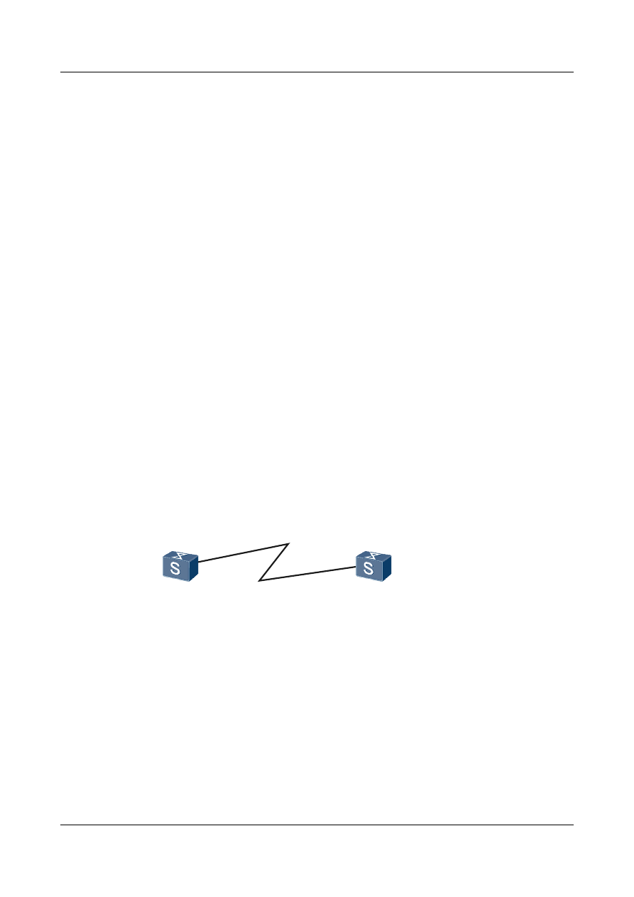
#
interface Pos1/0/0
link-protocol ppp
ppp authentication-mode chap
ppp chap user rta
ip address 10.110.0.1 255.255.255.0
#
aaa
local-user rtb password simple hello
#
return
l
Configuration file of Switch B
#
sysname SwitchB
#
interface Pos1/0/0
link-protocol ppp
ppp chap user rtb
ip address 10.110.0.2 255.255.255.0
#
aaa
local-user rta password simple hello
#
return
2.6.3 Example for Configuring Bidirectional CHAP Authentication
This example shows how to configure bidirectional CHAP authentication between two devices
in typical networking.
Networking Requirements
, Switch A and Switch B need to perform bidirectional CHAP
authentication.
Figure 2-3 Networking diagram of bidirectional CHAP authentication
POS1/0/0
10.110.0.1/24
POS1/0/0
10.110.0.2/24
Switch A
Switch B
Configuration Roadmap
The configuration roadmap is as follows:
1.
Configure the local user lists on Switch A and Route B.
2.
Configure local user names for Switch A and Switch B.
3.
Enable CHAP authentication on the interfaces of Switch A and Route B.
Data Preparation
To complete the configuration, you need the following data:
Quidway S9300 Terabit Routing Switch
Configuration Guide - WAN Access
2 PPP Configuration
Issue 02 (2011-07-15)
Huawei Proprietary and Confidential
Copyright © Huawei Technologies Co., Ltd.
35

l
User names of Switch A and Switch B
l
Passwords of Switch A and Switch B
l
IP address of the interface on Switch A
l
IP address of the interface on Switch B
NOTE
Switch A and Switch B must be configured with the same password, or the authentication fails.
Procedure
Step 1 Configure Switch A.
# Add the username and password of Switch B to the local user list of Switch A.
<Quidway> system-view
[Quidway] sysname SwitchA
[SwitchA] aaa
[SwitchA-aaa] local-user rtb password simple hello
[SwitchA-aaa] quit
# Configure an IP address for POS 1/0/0 and configure the link-layer encapsulation protocol as
PPP.
[SwitchA] interface pos 1/0/0
[SwitchA-Pos1/0/0] ip address 10.110.0.1 255.255.255.0
NOTE
l When you configure an IP address for an interface on a PPP link, if you delete the IP address of the
interface on the PPP link that fulfills the IPCP negotiation and assign this IP address to an interface on
another PPP link, the IPCP negotiation of the later PPP link is definitely unsuccessful. To solve this
problem, you can run the shutdown and undo shutdown commands on the former interface to restore
the IPCP negotiation or assign a new IP address to the later interface.
l When you configure an IP address for an interface on a PPP link, if the configuration is correct but the
negotiation is always unsuccessful, it is recommended that you assign a new IP address to the interface.
[SwitchA-Pos1/0/0] link-protocol ppp
# Configure the username of Switch A used in its authentication by Switch B in the CHAP mode.
[SwitchA-Pos1/0/0] ppp chap user rta
# Configure the authentication in CHAP mode.
[SwitchA-Pos1/0/0] ppp authentication-mode chap
Step 2 Configure Switch B.
# Add the username of Switch A and the local password to the local user list of Switch B.
<Quidway> system-view
[Quidway] sysname SwitchB
[SwitchB] aaa
[SwitchB-aaa] local-user rta password simple hello
[SwitchB-aaa] quit
# Configure an IP address for POS 1/0/0 and configure the link-layer encapsulation protocol as
PPP.
[SwitchB] interface pos 1/0/0
[SwitchB-Pos1/0/0] ip address 10.110.0.2 255.255.255.0
[SwitchB-Pos1/0/0] link-protocol ppp
# Configure the user name of Switch B used in its authentication by Switch A in the CHAP
mode.
Quidway S9300 Terabit Routing Switch
Configuration Guide - WAN Access
2 PPP Configuration
Issue 02 (2011-07-15)
Huawei Proprietary and Confidential
Copyright © Huawei Technologies Co., Ltd.
36

[SwitchB-Pos1/0/0] ppp chap user rtb
# Configure the authentication in CHAP mode.
[SwitchB-Pos1/0/0] ppp authentication-mode chap
Step 3 Verify the configuration.
After the configuration is completed, running the display interface command on every
switch, you can see the LCP status is Opened.
[SwitchA] display interface pos 1/0/0
Pos1/0/0 current state : UP
Line protocol current state : UP
Last line protocol up time : 2011-01-11 17:35:02
Description:HUAWEI, Quidway Series, Pos1/0/0 Interface
Route Port,The Maximum Transmit Unit is 4470, Hold timer is 10(sec)
Internet Address is 10.110.0.1/24
Link layer protocol is PPP
LCP opened, IPCP opened
Physical layer is Packet Over SDH
Clock: Master, Scramble, Loopback: none, CRC: 32
Threshold: SD 10e-6, SF 10e-3
Flag: J0 "NetEngine "
Flag: J1 "NetEngine "
Flag: C2 0x16
SDH error:
section layer: B1 0
line layer: B2 0
path layer: B3 0
Last 600 seconds input rate 72 bits/sec, 0 packets/sec
Last 600 seconds output rate 64 bits/sec, 0 packets/sec
Input peak rate 4380776 bits/sec,Record time: 2011-01-11 17:34:39
Output peak rate 1760 bits/sec,Record time: 2011-01-11 17:04:32
Input: 11490 packets, 2495499 bytes
Input error: 185 shortpacket, 0 longpacket, 10618 CRC, 5 lostpacket
Output: 445 packets, 20044 bytes
Output error: 0 lostpacket
Input bandwidth utilization : 0.01%
Output bandwidth utilization : 0.01%
----End
Configuration Files
l
Configuration file of Switch A
#
sysname SwitchA
#
interface Pos1/0/0
link-protocol ppp
ppp authentication-mode chap
ppp chap user rta
ip address 10.110.0.1 255.255.255.0
#
aaa
local-user rtb password simple hello
#
return
l
Configuration file of Switch B
#
sysname SwitchB
#
Quidway S9300 Terabit Routing Switch
Configuration Guide - WAN Access
2 PPP Configuration
Issue 02 (2011-07-15)
Huawei Proprietary and Confidential
Copyright © Huawei Technologies Co., Ltd.
37

interface Pos1/0/0
link-protocol ppp
ppp authentication-mode chap
ppp chap user rtb
ip address 10.110.0.2 255.255.255.0
#
aaa
local-user rta password simple hello
#
return
Quidway S9300 Terabit Routing Switch
Configuration Guide - WAN Access
2 PPP Configuration
Issue 02 (2011-07-15)
Huawei Proprietary and Confidential
Copyright © Huawei Technologies Co., Ltd.
38

3
HDLC and IP-Trunk Configuration
About This Chapter
The High-level Data Link Control (HDLC) is a bit-oriented link layer protocol. HDLC features
transparent transmission of any type of bit flow. A trunk can aggregate multiple interfaces into
an aggregation group to implement load balancing on member interfaces for received and sent
packets. At the same time, the connectivity can be of higher reliability.
3.1 HDLC and IP-Trunk Interface Overview
3.2 Features of HDLC and IP-Trunk interfaces on the switch
3.4 Configuring an IP-Trunk Interface
3.5 Maintaining HDLC and IP-Trunk Configuration
Quidway S9300 Terabit Routing Switch
Configuration Guide - WAN Access
3 HDLC and IP-Trunk Configuration
Issue 02 (2011-07-15)
Huawei Proprietary and Confidential
Copyright © Huawei Technologies Co., Ltd.
39

3.1 HDLC and IP-Trunk Interface Overview
The High-level Data Link Control (HDLC) is a typical bit-oriented synchronization data control
protocol. It adopts the full-duplex mode and CRC check. Its transmission control function is
independent of the processing function, and thus it features control capabilities and can be
flexibly used.
HDLC is featured by its transparent transmission of any kind of bit flow. The data is not required
to be a character set.
A trunk is aggregated by multiple ports among which load balancing is carried out. A trunk can
enhance the connection reliability.
Trunk interfaces are divided into Eth-Trunk interface and IP-Trunk interface.
The IP-Trunk consists of POS links only. The Eth-Trunk consists of Ethernet links only.
The IP-Trunk technology has the following advantages:
l
Increasing bandwidth: Bandwidth of an IP-Trunk interface is the sum of all the bandwidth
of member ports.
l
Enhancing reliability: If a member link failed, traffic is automatically switched to other
available links.
3.2 Features of HDLC and IP-Trunk interfaces on the switch
The protocols in the standard HDLC suite operate on synchronous serial lines. An IP-Trunk
consists of POS links only. The link layer protocol of the interfaces joining an IP-Trunk interface
must be HDLC.
The protocols in standard HDLC suite operate on the synchronous serial lines.
The IP-Trunk consists of POS links only. The link layer protocol of the member interface joining
the IP-Trunk interface must be HDLC.
An IP-Trunk interface has the following characteristics:
l
Supports configured IP addresses. When forwarding packets, each member interface uses
the IP address of the IP-Trunk interface.
l
Supports QoS based on physical ports rather than logical ports.
l
Supports hot backup and hot swap.
3.3 Configuring HDLC
This section describes how to configure basic HDLC functions. Detailed operations include
configuring the data link protocol of an interface as HDLC, an IP address for an interface, and
the polling interval.
3.3.1 Establishing the Configuration Task
Before configuring basic HDLC functions, familiarize yourself with the applicable environment,
complete the pre-configuration tasks, and obtain the required data. This can help you complete
the configuration task quickly and accurately.
Quidway S9300 Terabit Routing Switch
Configuration Guide - WAN Access
3 HDLC and IP-Trunk Configuration
Issue 02 (2011-07-15)
Huawei Proprietary and Confidential
Copyright © Huawei Technologies Co., Ltd.
40
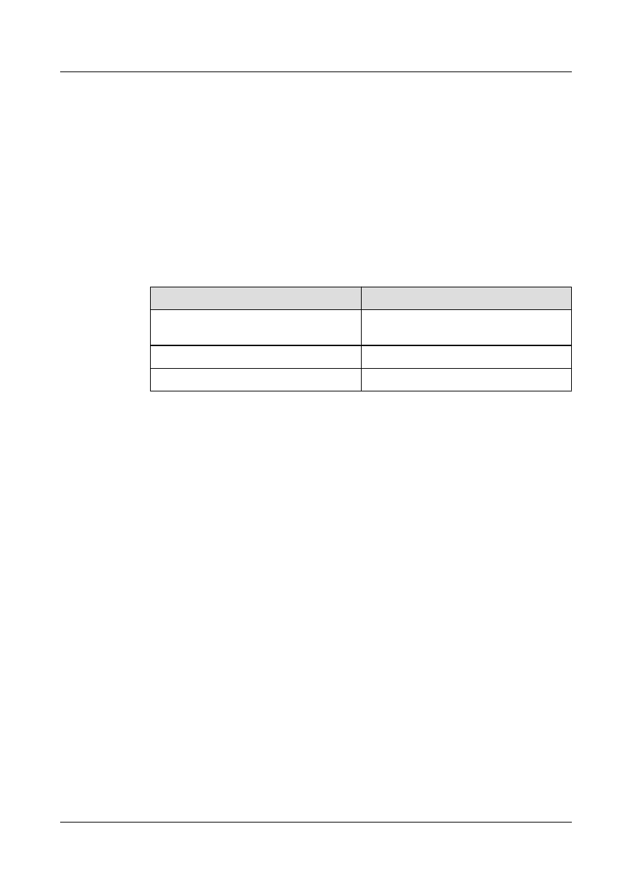
Applicable Environment
When you need to enable the bits synchronous transmission using the link layer protocol, you
can adopt the HDLC protocol.
Pre-configuration Tasks
Before configuring the basic HDLC functions, configure the physical attributes of the interface
to make the physical status of the interface become Up.
Data Preparation
To configure HDLC, you need the following data.
No.
Data
1
Number of the interface to be configured with
HDLC
2
Interface address
3
(Optional) Polling interval
3.3.2 Encapsulating an Interface with HDLC
The link layer protocol of the interfaces joining an IP-Trunk interface must be HDLC.
Procedure
Step 1 Run:
system-view
The system view is displayed.
Step 2 Run:
interface interface-type interface-number
The interface view is displayed.
Step 3 Run:
link-protocol hdlc
The interface is configured with HDLC.
By default, the interface is encapsulated with PPP.
----End
3.3.3 Configuring the IP Address of the Interface
You can assign an IP address to an interface.
Quidway S9300 Terabit Routing Switch
Configuration Guide - WAN Access
3 HDLC and IP-Trunk Configuration
Issue 02 (2011-07-15)
Huawei Proprietary and Confidential
Copyright © Huawei Technologies Co., Ltd.
41

Procedure
Step 1 Run:
system-view
The system view is displayed.
Step 2 Run:
interface interface-type interface-number
The interface view is displayed.
Step 3 Run:
ip address ip-address { mask | mask-length } [ sub ]
The IP address of the interface is configured.
----End
3.3.4 Setting the Polling Interval
You can configure the interval for the DTE to send status enquiry packets.
Procedure
Step 1 Run:
system-view
The system view is displayed.
Step 2 Run:
interface interface-type interface-number
The interface view is displayed.
Step 3 Run:
timer hold seconds
The polling interval is configured.
By default, the pooling interval is 10 seconds. If it is set to 0, then link detection is prohibited.
The HDLC adopt a polling timer to check the status of a link. Configure identical polling interval
on the both ends.
You can adopt the default polling interval or adjust the polling interval as required. In the case
of long network delay or high congestion, you can prolong the polling interval to reduce the
possibility of network flapping.
----End
3.3.5 Checking the Configuration
After basic HDLC functions are configured, you can view the status, link layer protocol and
configuration of the interface.
Prerequisite
The configurations of HDLC are complete.
Quidway S9300 Terabit Routing Switch
Configuration Guide - WAN Access
3 HDLC and IP-Trunk Configuration
Issue 02 (2011-07-15)
Huawei Proprietary and Confidential
Copyright © Huawei Technologies Co., Ltd.
42
Procedure
l
Run the display interface [ interface-type [ interface-number ] ] command to check the
status, link layer protocol and configuration of the interface.
----End
3.4 Configuring an IP-Trunk Interface
This section describes how to configure an IP-Trunk interface. Detailed operations include
creating an IP-Trunk interface and adding interfaces to the IP-Trunk interface, and configuring
an IP address for the IP-Trunk interface, the lower threshold of Up links.
3.4.1 Establishing the Configuration Task
Before configuring an IP-Trunk interface, familiarize yourself with the applicable environment,
complete the pre-configuration tasks, and obtain the required data. This can help you complete
the configuration task quickly and accurately.
Applicable Environment
To improve the communication ability of links, sometimes, multiple POS ports are bound to an
IP-Trunk interface. The bandwidth of an IP-Trunk interface is the sum of bandwidth of all the
member interfaces.
In addition, IP-Trunk interfaces can improve link reliability. If a member port is Down, traffic
is switched to other available ports.
Pre-configuration Tasks
None
Data Preparation
To create an IP-Trunk interface, you need the following data.
No.
Data
1
IP-Trunk ID
2
IP address of the IP-Trunk interface
3
Lower threshold of Up links
3.4.2 Creating an IP-Trunk and Adding Member Interfaces to the
IP-Trunk
You can create an IP-Trunk interface, add interfaces to the IP-Trunk interface, and configure
the member interfaces.
Quidway S9300 Terabit Routing Switch
Configuration Guide - WAN Access
3 HDLC and IP-Trunk Configuration
Issue 02 (2011-07-15)
Huawei Proprietary and Confidential
Copyright © Huawei Technologies Co., Ltd.
43

Procedure
l
In the IP-Trunk Interface View
Do as follows on the switchs that need to be configured with an IP-Trunk interface:
1.
Run:
system-view
The system view is displayed.
2.
Run:
interface ip-trunk trunk-id
An IP-Trunk is created.
3.
Run either of the following commands to add the member interfaces of the IP-Trunk.
–
Run the trunkport interface-type { interface-number1 [ to interface-number2 ] }
&<1-8> command to add member interfaces in batches.
–
Run the trunkport interfacetype interface-number command to add a member
interface.
When setting the member interface range, note that a maximum of 8 member interfaces
can be added or deleted for one time.
l
In the Member Interface View
Do as follows on the switchs that need to be configured with an IP-Trunk interface:
1.
Run:
system-view
The system view is displayed.
2.
Run:
interface ip-trunk trunk-id
An IP-Trunk is created.
3.
Run:
quit
Return to the system view.
4.
Run:
interface pos interface-number
The view of the interface to be added to the IP-Trunk is displayed.
5.
Run:
link-protocol hdlc
The link-layer protocol of the interface is configured as High-level Data Link Control
(HDLC). The link layer protocol of an interface to be added to the IP-Trunk must be
HDLC.
6.
Run:
ip-trunk trunk-id
The interface is added to the IP-Trunk.
When configuring an IP-Trunk interface, note the following points:
Quidway S9300 Terabit Routing Switch
Configuration Guide - WAN Access
3 HDLC and IP-Trunk Configuration
Issue 02 (2011-07-15)
Huawei Proprietary and Confidential
Copyright © Huawei Technologies Co., Ltd.
44

–
The link layer protocol of the interfaces that are added into an IP-Trunk interface
must be HDLC.
–
By default, the link layer protocol of a POS interface is PPP. You need to run the
link-protocol hdlc command in the POS interface view to change the link layer
protocol to HDLC.
–
Before adding an interface to an IP-Trunk, ensure the interface is not configured
with any Layer 3 feature or service.
–
A POS interface can join only one IP-Trunk interface. To add the POS interface
to another IP-Trunk interface, you must remove it from the original IP-Trunk first.
–
Member interfaces of an IP-Trunk cannot be IP-Trunks.
–
The POS interfaces of different interface boards can be added into the same IP-
Trunk.
–
Do not bind interfaces with different forwarding capabilities to an IP-Trunk.
–
After interfaces with different forwarding capabilities are bound to an IP-Trunk,
each interface assumes the least capability among all the interfaces. For example,
after a 10 Gbit/s POS interface and a 2.5 Gbit/s POS interface are added into an
IP-Trunk, the transmission capability of the 10 Gbit/s POS interface can only reach
2.5 Gbit/s. The transmission capability of the IP-Trunk is 5 Gbit/s rather than 12.5
Gbit/s.
–
If an IP-Trunk is created on a local device, the peer device interfaces that are
directly connected with the member interfaces must be bound to an IP-Trunk
interface. Otherwise, the two ends cannot communicate.
----End
3.4.3 Configuring an IP Address for the IP-Trunk Interface
You can assign an IP address to an IP-Trunk interface and configure member interfaces to borrow
the IP address of the IP-Trunk interface.
Context
Do as follows on the switchs that are configured with IP-Trunk interfaces.
Procedure
Step 1 Run:
system-view
The system view is displayed.
Step 2 Run:
interface ip-trunk trunk-id
The IP-Trunk interface view is displayed.
Step 3 Run:
ip address ip-address { mask | mask-length }
The IP address is configured for the IP-Trunk interface.
----End
Quidway S9300 Terabit Routing Switch
Configuration Guide - WAN Access
3 HDLC and IP-Trunk Configuration
Issue 02 (2011-07-15)
Huawei Proprietary and Confidential
Copyright © Huawei Technologies Co., Ltd.
45

3.4.4 (Optional) Configuring the Lower Threshold of Up Links
When the number of Up member interfaces of an IP-Trunk is less than the lower threshold, the
IP-Trunk goes Down.
Context
Do as follows on the switchs configured with IP-Trunk interfaces.
Procedure
Step 1 Run:
system-view
The system view is displayed.
Step 2 Run:
interface ip-trunk trunk-id
The view of the IP-Trunk interface is displayed.
Step 3 Run:
least active-linknumber link-number
The lower threshold of the member links in the Up state is configured.
By default, the lower threshold is 1. That is, an IP-Trunk remains Up as long as one member
interface is Up.
NOTE
To ensure normal forwarding, it is recommended to configure the same lower threshold on the Trunk
interfaces at both ends of the same Trunk link.
----End
3.4.5 Checking the Configuration
After an IP-Trunk interface is configured, you can view the status of the IP-Trunk interface,
information about the IP-Trunk member interfaces, and the forwarding table of the IP-Trunk
interface.
Prerequisite
The configurations of an IP-Trunk Interface are complete.
Procedure
l
Run the display interface ip-trunk [ trunk-id ] command to check the status of the IP-
Trunk interface.
l
Run the display trunkmembership ip-trunk trunk-id command to check information
about the IP-Trunk member interface.
l
Run the display trunkfwdtbl ip-trunk trunk-id [ slot slot-id ] command to check the
forwarding table of the IP-Trunk interface.
----End
Quidway S9300 Terabit Routing Switch
Configuration Guide - WAN Access
3 HDLC and IP-Trunk Configuration
Issue 02 (2011-07-15)
Huawei Proprietary and Confidential
Copyright © Huawei Technologies Co., Ltd.
46

Example
Run the display interface ip-trunk command. If the physical status, link protocol status, IP
address, and load-balancing mode of the IP-Trunk interface are displayed, it means the
configuration succeeds. For example:
<Quidway> display interface ip-trunk 10
Ip-Trunk10 current state : DOWN
Line protocol current state : DOWN
Description:HUAWEI, Quidway Series, Ip-Trunk10 Interface
Route Port,Hash arithmetic : According to SIP-XOR-DIP, Maximal BW: 155M, Current
BW: 0M, The Maximum Transmit Unit is 4470
Internet Address is 2.2.2.2/24 Link layer protocol is nonstandard HDLC
Physical is IP_TRUNK
Last 300 seconds input rate 0 bits/sec, 0 packets/sec
Last 300 seconds output rate 0 bits/sec, 0 packets/sec
Realtime 0 seconds input rate 0 bits/sec, 0 packets/sec
Realtime 0 seconds output rate 0 bits/sec, 0 packets/sec
Input: 0 packets,0 bytes,
0 unicast,0 broadcast,0 multicast
0 errors,0 drops,0 unknownprotocol
Output:0 packets,0 bytes,
0 unicast,0 broadcast,0 multicast
0 errors,0 drops
Input bandwidth utilization : 0.00%
Output bandwidth utilization : 0.00%
-----------------------------------------------------
PortName Status Weight
-----------------------------------------------------
Pos2/1/2 DOWN 1
-----------------------------------------------------
The Number of Ports in Trunk : 1
The Number of UP Ports in Trunk : 0
Run the display trunkmembership ip-trunk command. If the member interfaces, number of
members, and number of Up members are displayed, it means the configuration succeeds. For
example:
<Quidway> display trunkmembership ip-trunk 1
Trunk ID: 1
TYPE: pos
Number Of Ports in Trunk = 1
Number Of UP Ports in Trunk = 0
operate status: down
Run the display trunkfwdtbl ip-trunk command. You can view the forwarding table of an IP-
Trunk interface.
<Quidway> display trunkfwdtbl ip-trunk 1
Ip-Trunk1's forwarding table is:
Pos5/0/1
Pos5/0/1
Pos5/0/1
Pos5/0/1
Pos5/0/1
Pos5/0/1
Pos5/0/1
Pos5/0/1
3.5 Maintaining HDLC and IP-Trunk Configuration
This section describes how to maintain HDLC. Detailed operations include clearing the statistics
about the HDLC interfaces.
Quidway S9300 Terabit Routing Switch
Configuration Guide - WAN Access
3 HDLC and IP-Trunk Configuration
Issue 02 (2011-07-15)
Huawei Proprietary and Confidential
Copyright © Huawei Technologies Co., Ltd.
47

3.5.1 Clearing the statistics of the HDLC or IP-Trunk interfaces
You can run the reset commands to clear interface statistics before recollecting traffic statistics
on the interface.
Context
CAUTION
The previous statistics cannot be restored after you clear them. So, confirm the action before
you use the command.
To reset the interface statistics of the Network Management System (NMS) or that displayed by
running the display interface command, run the following commands in the user view.
NOTE
For the display of interface statistics in the NMS, refer to related NMS manuals.
Procedure
l
Run the reset counters interface [ interface-type [ interface-number ] ] command to clear
the interface statistics displayed by running the display interface command.
----End
3.6 Configuration Examples
This section provides several examples for HDLC and IP-Trunk. These configuration examples
explain the networking requirements, configuration roadmap, data preparation, configuration
procedure, and configuration files.
3.6.1 Example for Configuring HDLC
This example shows how to configure HDLC to interconnect devices in typical networking.
Networking Requirements
Switch A and Switch B are connected by POS interfaces, and the interfaces are required to run
HDLC.
Figure 3-1 Networking diagram of the HDLC functions
POS1/0/0
POS1/0/0
100.1.1.2/24
Switch A
Switch B
100.1.1.1/24
Quidway S9300 Terabit Routing Switch
Configuration Guide - WAN Access
3 HDLC and IP-Trunk Configuration
Issue 02 (2011-07-15)
Huawei Proprietary and Confidential
Copyright © Huawei Technologies Co., Ltd.
48

Configuration Roadmap
The configuration roadmap is as follows:
1.
Configure the link protocol of each interface to HDLC.
2.
Configure the IP address of each interface.
Data Preparation
To configure DHCP, you need the following data:
l
IP address of the interface on Switch A
l
IP address of the interface on Switch B
NOTE
The IP addresses of Switch A and Switch B must be in the same network segment, or the link layer cannot
be Up.
Procedure
Step 1 Configure Switch A.
<Quidway> system-view
[Quidway] sysname SwitchA
[SwitchA] interface pos 1/0/0
[SwitchA-Pos1/0/0] link-protocol hdlc
[SwitchA-Pos1/0/0] ip address 100.1.1.1 24
[SwitchA-Pos1/0/0] quit
Step 2 Configure Switch B.
<Quidway> system-view
[Quidway] sysname SwitchB
[SwitchB] interface pos 1/0/0
[SwitchB-Pos1/0/0] link-protocol hdlc
[SwitchB-Pos1/0/0] ip address 100.1.1.2 24
[SwitchB-Pos1/0/0] quit
Step 3 Verify the configuration.
After the configuration is completed, Switch A and Switch B can ping through each other.
Take Switch A as an example.
[SwitchA] ping 100.1.1.2
PING 100.1.1.2: 56 data bytes, press CTRL_C to break
Reply from 100.1.1.2: bytes=56 Sequence=1 ttl=255 time=31 ms
Reply from 100.1.1.2: bytes=56 Sequence=2 ttl=255 time=31 ms
Reply from 100.1.1.2: bytes=56 Sequence=3 ttl=255 time=31 ms
Reply from 100.1.1.2: bytes=56 Sequence=4 ttl=255 time=31 ms
Reply from 100.1.1.2: bytes=56 Sequence=5 ttl=255 time=31 ms
--- 100.1.1.2 ping statistics ---
5 packet(s) transmitted
5 packet(s) received
0.00% packet loss
round-trip min/avg/max = 31/31/31 ms
Run the display ip routing-table command to check the correctness of the routing table.
[SwitchA] display ip routing-table
Route Flags: R - relied, D - download to fib
------------------------------------------------------------------------------
Routing Tables: Public
Destinations : 4 Routes : 4
Destination/Mask Proto Pre Cost Flags NextHop Interface
Quidway S9300 Terabit Routing Switch
Configuration Guide - WAN Access
3 HDLC and IP-Trunk Configuration
Issue 02 (2011-07-15)
Huawei Proprietary and Confidential
Copyright © Huawei Technologies Co., Ltd.
49
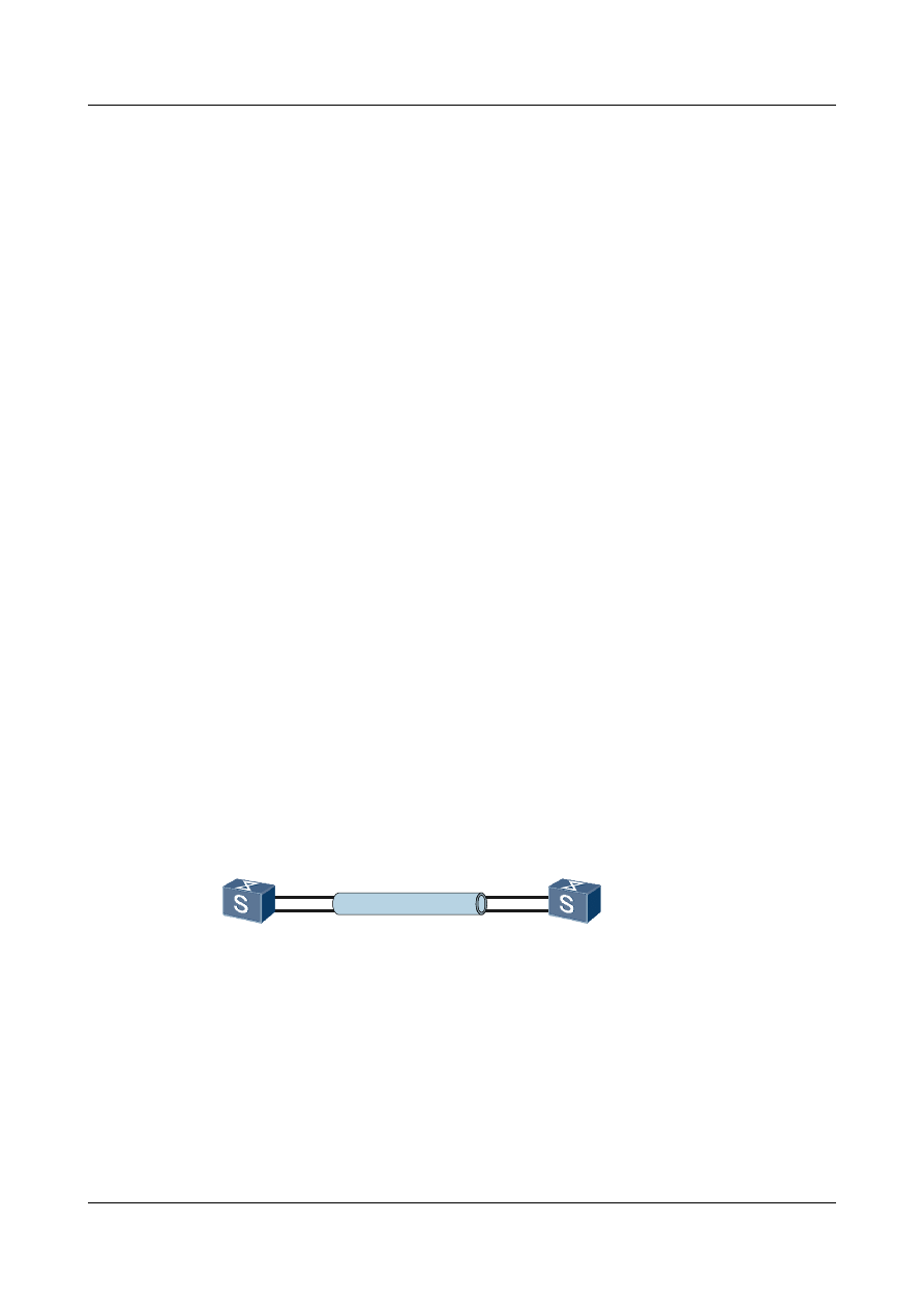
100.1.1.0/24 Direct 0 0 D 100.1.1.1 Pos1/0/0
100.1.1.1/32 Direct 0 0 D 127.0.0.1 InLoopBack0
127.0.0.0/8 Direct 0 0 D 127.0.0.1 InLoopBack0
127.0.0.1/32 Direct 0 0 D 127.0.0.1 InLoopBack0
----End
Configuration Files
l
Configuration file of Switch A
#
sysname SwitchA
#
interface Pos1/0/0
link-protocol hdlc
ip address 100.1.1.1 255.255.255.0
#
return
l
Configuration file of Switch B
#
sysname SwitchB
#
interface Pos1/0/0
link-protocol hdlc
ip address 100.1.1.2 255.255.255.0
#
return
3.6.2 Example for Configuring an IP-Trunk
This example shows how to configure IP-Trunk logical links to interconnect devices in typical
networking.
Networking Requirements
Create an IP-Trunk between Switch A and Switch B.
Figure 3-2 Configuring an IP-Trunk
POS1/0/0
POS1/0/0
Switch A
Switch B
POS2/0/0
POS2/0/0
IP-Trunk1
100.1.1.1/24
IP-Trunk1
100.1.1.2/24
Configuration Roadmap
The configuration roadmap is as follows:
1.
Create an IP-Trunk interface.
2.
Add the POS interfaces to the IP-Trunk interface.
Quidway S9300 Terabit Routing Switch
Configuration Guide - WAN Access
3 HDLC and IP-Trunk Configuration
Issue 02 (2011-07-15)
Huawei Proprietary and Confidential
Copyright © Huawei Technologies Co., Ltd.
50

Data Preparation
To complete the configuration, you need the following data:
l
Switch A and Switch B are connected through the POS interfaces.
l
IP address of the IP-Trunk interface at Switch A
l
IP address of the IP-Trunk interface at Switch B
Procedure
Step 1 Configure Switch A.
<Quidway> system-view
[Quidway] sysname SwitchA
# Create IP-Trunk 1 and configure an IP address for it.
[SwitchA] interface ip-trunk 1
[SwitchA-Ip-Trunk1] ip address 100.1.1.1 255.255.255.0
[SwitchA-Ip-Trunk1] quit
# Add POS 1/0/0 and POS 2/0/0 to IP-Trunk 1.
[SwitchA] interface pos 1/0/0
[SwitchA-Pos1/0/0] link-protocol hdlc
[SwitchA-Pos1/0/0] ip-trunk 1
[SwitchA-Pos1/0/0] quit
[SwitchA] interface pos 2/0/0
[SwitchA-Pos2/0/0] link-protocol hdlc
[SwitchA-Pos2/0/0] ip-trunk 1
[SwitchA-Pos2/0/0] quit
Step 2 Configure Switch B.
<Quidway> system-view
[Quidway] sysname SwitchB
# Create IP-Trunk 1 and configure an IP address for it.
[SwitchB] interface Ip-Trunk 1
[SwitchB-Ip-Trunk1] ip address 100.1.1.2 255.255.255.0
[SwitchB-Ip-Trunk1] quit
# Add POS 1/0/0 and POS 2/0/0 to IP-Trunk 1.
[SwitchB] interface pos 1/0/0
[SwitchB-Pos1/0/0] link-protocol hdlc
[SwitchB-Pos1/0/0] ip-trunk 1
[SwitchB-Pos1/0/0] quit
[SwitchB] interface pos 2/0/0
[SwitchB-Pos2/0/0] link-protocol hdlc
[SwitchB-Pos2/0/0] ip-trunk 1
[SwitchB-Pos2/0/0] quit
Step 3 Check the configuration.
Run the display interface ip-trunk command on Switch A or Switch B, and you can find that
the interface is Up.
Take Switch A as an example.
[SwitchA] display interface ip-trunk 1
Ip-Trunk1 current state : UP
Line protocol current state : UP
Last line protocol up time : 2011-01-12 18:15:05
Description:HUAWEI, Quidway Series, Ip-Trunk1 Interface
Route Port,Hash arithmetic : According to SIP-XOR-DIP,Maximal BW: 310M, Current
BW: 310M, The Maximum Transmit Unit is 4470
Quidway S9300 Terabit Routing Switch
Configuration Guide - WAN Access
3 HDLC and IP-Trunk Configuration
Issue 02 (2011-07-15)
Huawei Proprietary and Confidential
Copyright © Huawei Technologies Co., Ltd.
51

Internet Address is 100.1.1.1/24 Link layer protocol is nonstandard HDLC
Physical is IP_TRUNK
Last 30 seconds input rate 112 bits/sec, 0 packets/sec
Last 30 seconds output rate 64 bits/sec, 0 packets/sec
Realtime 0 seconds input rate 0 bits/sec, 0 packets/sec
Realtime 0 seconds output rate 0 bits/sec, 0 packets/sec
Input: 71 packets,4972 bytes,
0 unicast,0 broadcast,0 multicast
0 errors,0 drops,0 unknownprotocol
Output:69 packets,3036 bytes,
0 unicast,0 broadcast,0 multicast
0 errors,0 drops
Input bandwidth utilization : 0.01%
Output bandwidth utilization : 0.01%
-----------------------------------------------------
PortName Status Weight
-----------------------------------------------------
Pos1/0/0 UP 1
Pos2/0/0 UP 1
-----------------------------------------------------
The Number of Ports in Trunk : 2
The Number of UP Ports in Trunk : 2
View information about the member port of the IP-Trunk interface on Switch A.
[SwitchA] display trunkmembership ip-trunk 1
Trunk ID: 1
TYPE: pos
Number Of Ports in Trunk = 2
Number Of UP Ports in Trunk = 2
operate status: up
Interface Pos1/0/0, valid, selected, operate up, weight=1,
Interface Pos2/0/0, valid, selected, operate up, weight=1,
The IP-Trunk interface of Switch A and that of Switch B can ping each other successfully.
[SwitchA] ping -a 100.1.1.1 100.1.1.2
PING 100.1.1.2: 56 data bytes, press CTRL_C to break
Reply from 100.1.1.2: bytes=56 Sequence=1 ttl=255 time=62 ms
Reply from 100.1.1.2: bytes=56 Sequence=2 ttl=255 time=62 ms
Reply from 100.1.1.2: bytes=56 Sequence=3 ttl=255 time=62 ms
Reply from 100.1.1.2: bytes=56 Sequence=4 ttl=255 time=62 ms
Reply from 100.1.1.2: bytes=56 Sequence=5 ttl=255 time=62 ms
--- 100.1.1.2 ping statistics ---
5 packet(s) transmitted
5 packet(s) received
0.00% packet loss
round-trip min/avg/max = 62/62/62 ms
----End
Configuration Files
l
Configuration file of Switch A
#
sysname SwitchA
#
interface Ip-Trunk1
ip address 100.1.1.1 255.255.255.0
#
interface Pos1/0/0
link-protocol hdlc
ip-trunk 1
#
interface Pos2/0/0
link-protocol hdlc
ip-trunk 1
#
Quidway S9300 Terabit Routing Switch
Configuration Guide - WAN Access
3 HDLC and IP-Trunk Configuration
Issue 02 (2011-07-15)
Huawei Proprietary and Confidential
Copyright © Huawei Technologies Co., Ltd.
52

return
l
Configuration file of Switch B
#
sysname SwitchB
#
interface Ip-Trunk1
ip address 100.1.1.2 255.255.255.0
#
interface Pos1/0/0
link-protocol hdlc
ip-trunk 1
#
interface Pos2/0/0
link-protocol hdlc
ip-trunk 1
#
return
Quidway S9300 Terabit Routing Switch
Configuration Guide - WAN Access
3 HDLC and IP-Trunk Configuration
Issue 02 (2011-07-15)
Huawei Proprietary and Confidential
Copyright © Huawei Technologies Co., Ltd.
53
Document Outline
- About This Document
- Contents
- 1 POS Interface Configuration
- 1.1 Overview of POS and CPOS Interfaces
- 1.2 POS Interface Features Supported by the S9300
- 1.3 Configuring POS Interfaces
- 1.3.1 Establishing the Configuration Task
- 1.3.2 Configuring the Link-Layer Protocol on the POS Interface
- 1.3.3 Configuring Clock Mode
- 1.3.4 Configuring Overhead Bytes
- 1.3.5 Configuring Frame Format
- 1.3.6 Configuring the Scramble Function
- 1.3.7 Configuring the Length of the CRC Check Character
- 1.3.8 Configuring MTU
- 1.3.9 Setting Alarm Thresholds on a POS Interface
- 1.3.10 Checking the Configuration
- 1.4 Maintaining POS Interface Configuration
- 1.5 Configuration Examples
- 2 PPP Configuration
- 2.1 PPP Overview
- 2.2 PPP Features Supported by the S9300
- 2.3 Setting PPP Parameters
- 2.3.1 Establishing the Configuration Task
- 2.3.2 Encapsulating the Interface with PPP
- 2.3.3 Configuring the Timeout Period of Negotiation
- 2.3.4 Configuring the Polling Interval
- 2.3.5 Preventing the Peer Host Route from Being Added to the Local Routing Table of Direct Routes
- 2.3.6 Checking the Configuration
- 2.4 Configuring Unidirectional PAP
- 2.5 Configuring Unidirectional CHAP
- 2.6 Configuration Examples
- 3 HDLC and IP-Trunk Configuration
Wyszukiwarka
Podobne podstrony:
Ebook Competitive Pstn, Wan Access Using Ss7(1)
ADVAC%20Tech%20Guide%2003 02
59487272 Accessing the WAN Student Skills Based Assessment Lab Answer Key
NS2 lab 6 2 12a en Configure Remote Access Using Cisco Easy VPN
Design Guide 02 Design of Steel and Composite Beams with Web Openings
02 Access tworzenie kwerendy wybierającej w widoku projektu
ADVAC%20Tech%20Guide%2003 02
więcej podobnych podstron