
WSJT
User’s Guide
and
Reference Manual
Version 2.2.2
July 24, 2002
Manual Copyright
2002
by
Joe Taylor, K1JT and Andy Flowers, K0SM

......................................................................................1
.........................................................................................4
............................................................................................5
............................................................................................9
......................................................................................9
OPERATING IN FSK441 MODE ........................................................................10
..........................................................................................12
QSO...........................................................................12
...............................................................................13
...........................................................13
........................................................................................16
...............................................................................................20
.............................................................................27
...............................................................................28
........................................................................................28
2

APPENDIX: SPECIFICATIONS OF THE SIGNAL PROTOCOLS .....................36
FSK441...............................................................................................................36
JT44....................................................................................................................37
3

Introduction
WSJT is the name of a computer program. It stands for “Weak Signal
communications, by K1JT.” The program currently supports two communication
modes, known as FSK441 and JT44.
FSK441 is designed for high speed meteor scatter communication using the brief
“pings” of signals reflected from the ionized trails of meteors at about 100 km
height. Such pings are typically a few dB above the receiver noise and may last
from ten to a few hundred milliseconds. By using these brief pings, FSK441
facilitates QSOs in the range 500 to 1400 miles (800 to 2200 km) in the amateur
2-meter and other VHF bands.
In contrast, JT44 is designed for communications with very weak signals of
roughly constant strength. The program is able to work al levels 10 dB or more
below the weakest intelligible CW signals, and this makes JT44 ideal for
tropospheric scatter, ionospheric scatter, and Earth-Moon-Earth (EME)
communications. Smaller stations are able to complete EME QSOs much more
readily with JT44 than with more traditional communication modes.
System Requirements
WSJT is designed for computers running the Microsoft Windows operating
system. Windows 95, 98, 98/SE, ME, NT, 2000, and XP have all been used
successfully. Minimum hardware requirements include a 75 MHz Pentium or
equivalent CPU, 24 MB of RAM, 40 MB of free disk space, a monitor with 800 x
600 or higher resolution, and a Windows compatible sound card. Recent
versions of Windows will require more memory, and a faster CPU may be
desirable if you run other programs while using WSJT. You will need a simple
computer-to-radio interface like those required for other sound card modes such
as PSK31. The DTR or RTS line of a serial communication (COM) port is used to
key the push-to-talk (PTT) line of the transmitter. Connections must be made
between the transceiver audio output and computer sound card input, and vice
versa. Station accessories that accomplish these things are easy to build and
available commercially from a number of sources.
Both FSK441 and JT44 require time synchronization between the transmitting
and receiving stations. You will need a method of setting your computer clock to
an accuracy of one second or better, and keeping it set. Many operators use an
internet clock-setting program, while others use a GPS receiver. You may chose
to set the computer clock manually to WWV or another broadcast time service,
but this procedure can be cumbersome and you will have to watch it carefully.
Computer clocks tend to drift. Do not set your clock to UTC at the beginning of
an EME or meteor-scatter schedule and expect it to be accurate half an hour
later!
4

Installation
WSJT is available for free download at pulsar.princeton.edu/~joe/K1JT
and at the European mirror site www.vhfdx.de. Download the file
WSJT222.EXE, or a similar file name with a higher version number, if one exists.
Execute this file install WSJT to a permanent location of your choice. If you have
obtained the program on a CD-ROM, run the program WSJT222.EXE to install
WSJT.
If you discover that an update to WSJT has been released and you wish to
upgrade to the new version, download the appropriate update file. It will be
named something like UPD221.EXE (signifying an upgrade to version 2.2.1), and
will be a much shorter file than the full installation package. Execute the file to
install the upgrade. Typically, the installation process will copy new versions of
the files WSJT.EXE and WSJT1.DLL (and possibly one or two other files) over
your existing copies. Be sure that they are installed in the same directory that
you previously used to install WSJT.
Initial Setup
Connect the appropriate interface cables between the computer and your radio.
If you need help with details of the hardware interface, refer to one of many
available descriptions of the station setups for other sound card modes — for
example, WB8IMY's article on PSK31 in QST for May 2000.
To start the WSJT program, double-click its Windows desktop icon or select it
from the Windows “Start” menu. When first launched, WSJT will start in FSK441
mode. (To be sure you are in FSK441 mode, you may press function key F7.)
You should then go through the following steps, in sequence.
Station Parameters
Select Setup | Options and enter your callsign in the My call text box and your
6-digit Maidenhead grid locator in the Grid locator box. If you keep your
computer clock on local time, enter the correct UTC offset in hours. If your
location is east of Greenwich, the offset should be negative. Depending on
details of your station's T/R switching mechanism, you may want to enter values
of a few tenths of a second or more for RX delay, TX delay, or both, to avoid
hot-switching your antenna relay or recording switching transients on receive.
To enable periodic station identification in FSK441 mode, enter the desired
interval in minutes under ID interval. To activate this feature you must also
provide an audio file named ID.WAV and containing the desired announcement
in the installation directory. It can be a voice or CW recording, or indeed any
recording of your choice. Automatic station identification is not presently
implemented in JT44 mode.
5

Click NA Defaults to select FSK441 message templates based on customary
practices in North America, or EU Defaults for European-style messages. You
may edit the templates if you prefer a slightly different message format, but be
aware that changing the format by very much could have the effect of confusing
your QSO partner. (These selections have no effect on the default messages in
JT44 mode.) Click on Done to dismiss the Options screen and return to the
main screen.
T/R Switching
Select menu item Setup | Set COM Port and enter the number of the COM port
you wish to use. Entering “0” will disable automatic PTT switching, which you
might choose to do if you will use VOX control. Next you should indicate on the
Setup menu whether you wish to use the DTR or RTS line for PTT control. Note
that you can both “check” and “uncheck” items on this menu. If you do not know
whether your interface is wired for DTR or RTS, try checking both. If you are
making your own interface for PTT control, note that the standard 9-pin serial
port connector uses pin 4 for DTR, pin 7 for RTS, and pin 5 for ground.
Click one of the four Tune buttons labeled A, B, C, or D to be sure that T/R
switching works i.e., that the PTT line of your radio is keyed. Each tune button
causes one of the four FSK441 audio tones to be sent to your radio via the
sound card output. Be aware that all transmissions with WSJT are intended to
produce full-amplitude, key-down carriers with 100% duty cycle. For
comparison, the on-off keying of CW yields roughly a 50% duty cycle. If a high
duty cycle for a 30-second transmission will overstress your final amplifier,
reduce power accordingly. Click TX Stop to stop transmitting.
RX Audio Level
The next step is to adjust the receiver audio level and the sound card audio gain.
If your radio provides a way to control the Automatic Gain Control (AGC), turn it
off or to its “fast” position. It may also help to turn down the RF gain control and
turn off the noise blanker. You will probably want to experiment with the noise
blanker later; with many radios, WSJT signals are not adversely affected by the
noise blanker, but in other cases meteor-scatter pings can be severely clipped.
Most noise blankers should be usable and effective in JT44 mode.
With WSJT running in FSK441 mode and the receiver tuned to a clear
frequency, click Record to start a receiving period. In the first panel of the status
bar at the bottom of the WSJT screen you should see an entry of the form “File:
callsign_yymmdd_hhmmss”. The callsign part of this long file name comes from
the To radio text box, while “yymmdd” and “hhmmss” represent the current date
and time. In the second panel of the status bar you should see “File Position: n
s”, where “n” is an integer counting off the seconds of recording to the named
file. After recording a few seconds of audio, click Stop. A third message should
6
appear in the middle panel of the status bar saying “RX Noise: x dB”. This
message describes the level of received noise as digitized by the sound card,
expressed in dB relative to the optimum level.
A jagged green line should appear in the large plot area, along with a two-
dimensional waterfall-style spectrogram. The green line is a graph of received
noise power (vertical axis) over the time you were recording (horizontal axis).
The waterfall plot is a time vs. frequency spectrogram of the received audio. If
you see no green line and no spectrogram, there's probably no receiver noise (or
not enough noise) going into the sound card.
Adjust the receiver audio gain and/or the computer's “line in” volume control and
repeat the short recordings until you establish a noise level close to 0 dB. The
value is not overly critical: ± 2 or 3 dB from the nominal 0 dB should be fine. The
computer's sound mixer may present you with several adjustable sliders as
volume controls, and you may have to try them all to find the right one. You may
also want to experiment with using the “microphone in” connector instead of “line
in” for interfacing to the receiver. Be sure that all sound card special effects such
as tone controls and “3-D Sound” are turned off.
7

When the recording level is properly adjusted the wavy green line will appear
below the waterfall spectrogram and approximately aligned with the short
horizontal tick marks just outside the edges of the plot area. WSJT displays a
message if the receiver audio level is extremely low or there is no audio at all. If
this occurs, check to make sure your cables are connected and that you have
selected the correct audio input channel on the Windows mixer.
You may find the optimum mixer settings for WSJT to be different from those of
other programs you use. If you intend to switch often between different
programs, you will have to readjust the controls for that particular program.
There are free utility programs (such as “QuickMix”) that will store your mixer
settings and allow you to switch them easily when you change programs.
TX Audio Level
Both FSK441 and JT44 use frequency-shift keying to send information. FSK441
uses 4 audio tones to drive the transmitter, while JT44 uses 44 tones. When
transmitting in either mode, it is important that each tone produce nearly the
same output power.
Tune your radio to a clear frequency (or better yet, use a dummy load) and click
the four Tune buttons A, B, C, and D in order. These actions will cause the
transmission of pure tones at 882, 1323, 1764, and 2205 Hz, respectively,
relative to the radio’s suppressed carrier frequency. Check the transmitter power
output (or the final amplifier current, or some other relative indicator) while
transmitting each tone. Variations of 10% or even 20% among the four tones are
acceptable, but 50% differences will significantly deteriorate the ability of other
stations to read your signal under marginal conditions. In a properly adjusted
transmitter the power level of any multi-tone message should also be the same
as that of any single-tone transmission.
Unlike the situation with PSK31, it is not necessary to reduce audio gain in the
transmitter to preserve linearity and minimize distortion. Indeed, turning up the
audio gain may be all you need do to equalize your transmitted power in the four
tones. Activating the speech processor may also help to level your transmitted
spectrum. Such simple measures should be tried before resorting to the
individual adjustment of tone amplitudes described next.
A means is provided on the Setup | Options screen to set amplitudes of the four
FSK441 tones separately. Relative numerical values may be entered to scale
the generated amplitudes as desired. Note that the numerical values should fall
in the range 0.0 to 1.0 and that they represent voltage, not power. If, for
example, you find that tone D produces twice the power output of all the other
tones, you should reduce the numerical amplitude of tone D to 0.707 (the square
root of 0.5) to compensate. The amplitude settings have no effect in JT44 mode.
8

Frequency Readout
By convention FSK441 and JT44 are used with the transceiver set to USB mode.
For scheduling and other purposes, the frequency of operation is stated as that
of the suppressed carrier, or more simply, the frequency displayed on the dial.
Note, however, that the dial readings of many radios are not calibrated as
accurately as might be desired. Before operating, you should do your best to
assure that you are transmitting and receiving within 100 or 200 Hz of the
desired frequency.
The easiest way to do this is to feed a small sample of transmitter output to a
well-calibrated frequency counter. The counter reading will be the frequency of
the audio tone added to that of the suppressed carrier. After setting up the test
equipment, click one of the “Tune” buttons to transmit a single tone. For
example, tune your radio to 144150.000 kHz USB and press the “A” button to
activate the transmitter and generate an audio tone of 882 Hz. The frequency
counter should read 144150.882 kHz. If the counter reads higher (or lower) than
this amount and you trust its calibration, you will need to compensate by tuning
your radio lower (or higher) by the same amount every time you operate.
Many inexpensive counters will not read to the nearest Hz when measuring
frequencies in the VHF range. Note, however, that an accuracy of about 100 Hz
is more than adequate for either of the WSJT modes. In the example given
above, suppose you set your radio to 144150.000 kHz USB and send an 882 Hz
tone, and your counter reads 144150.4 kHz. Adjust the tuning dial until the
counter reads 144150.9 kHz, which is close enough to the nominal frequency of
144150.882 kHz. Say the dial then reads 144150.475 kHz. You would conclude
that the radio's calibration is 475 Hz low. Every time you run a schedule with
another station you should remember to set the dial frequency higher than the
schedule frequency by that amount.
Amplifier Requirements
At any instant, an FSK441 or JT44 transmission consists of a single-frequency
sine wave. There is no “key up” time during a transmission, and one tone
changes to the next one in a phase-continuous manner. As a result, neither
FSK441 nor JT44 requires a high degree of linearity in your power amplifiers. As
with the traditional two-tone FSK systems used for RTTY, the signal
characteristics present no opportunities for generating inter-modulation products.
This means that you may send an FSK441 or JT44 signal through a class C or
other highly nonlinear amplifier if you wish, without creating unwanted sidebands
or splatter. (NB: Do not use a voice ID recording if you use a nonlinear
amplifier.) Keep in mind that if full amplitude transmissions lasting for 30 or 60
seconds will overheat your final amplifier, you should reduce power.
9
Operating in FSK441 Mode
Receiving FSK441
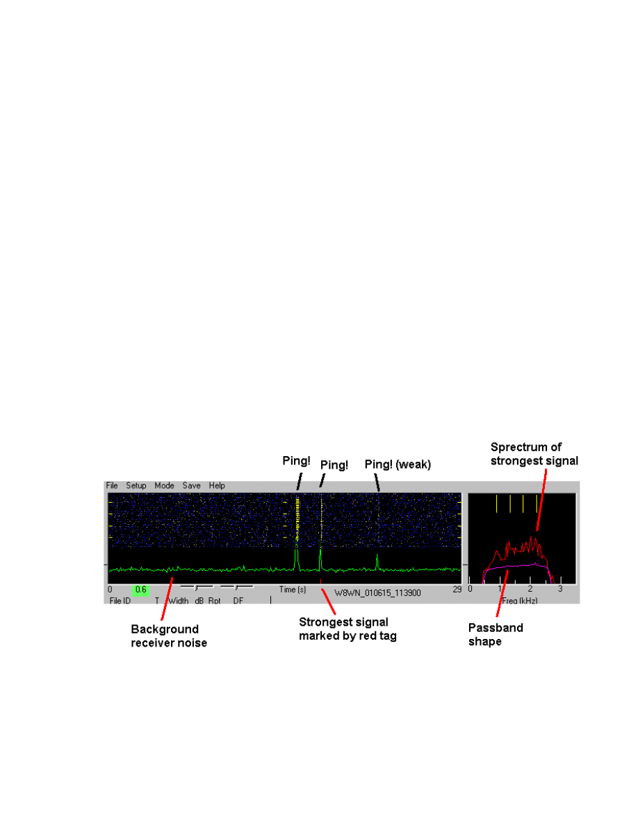
WSJT displays a received signal graphically at the end of each recording period.
The green-line graph of signal strength vs. time represents power (proportional
to the square of the receiver output voltage), smoothed over 0.1 s intervals for
plotting. Pings appear on this plot as upward-going spikes above the grassy
baseline. Full scale (to the top of the plot area) represents a signal 30 dB above
the fluctuations in receiver noise power.
Recordings of receiver noise in FSK441 mode also produce a purple curve in the
small plot area at the upper right, along with four yellow tick marks above the
curve. The purple line illustrates the average spectrum of received noise and
therefore (in the absence of signal) represents your receiver's passband shape,
including the effects of IF and audio filters and the sound card interface. The
vertical scale is in dB, with the length of the yellow tick marks equal to 10 dB.
The tick marks at the top of the window denote the frequencies of the four tones
used by FSK441, namely 882, 1323, 1764, and 2205 Hz. Ideally, your receiver
passband shape should be approximately flat – that is, the purple curve should
be nearly horizontal on the graph – from about 600 to 2500 Hz. If this is not the
case with your receiver, WSJT software will do its best to compensate
automatically.
A red curve may also appear in the smaller plot area. Its meaning is similar to
that of the purple curve, except that it represents the spectrum of the strongest
ping-like signal found by the decoding algorithm. There will be no red curve if no
ping was detected. A small red tick mark will appear along the bottom edge of
10

the large plot area to identify the signal region whose spectrum has been plotted
in red.
Decoded Text
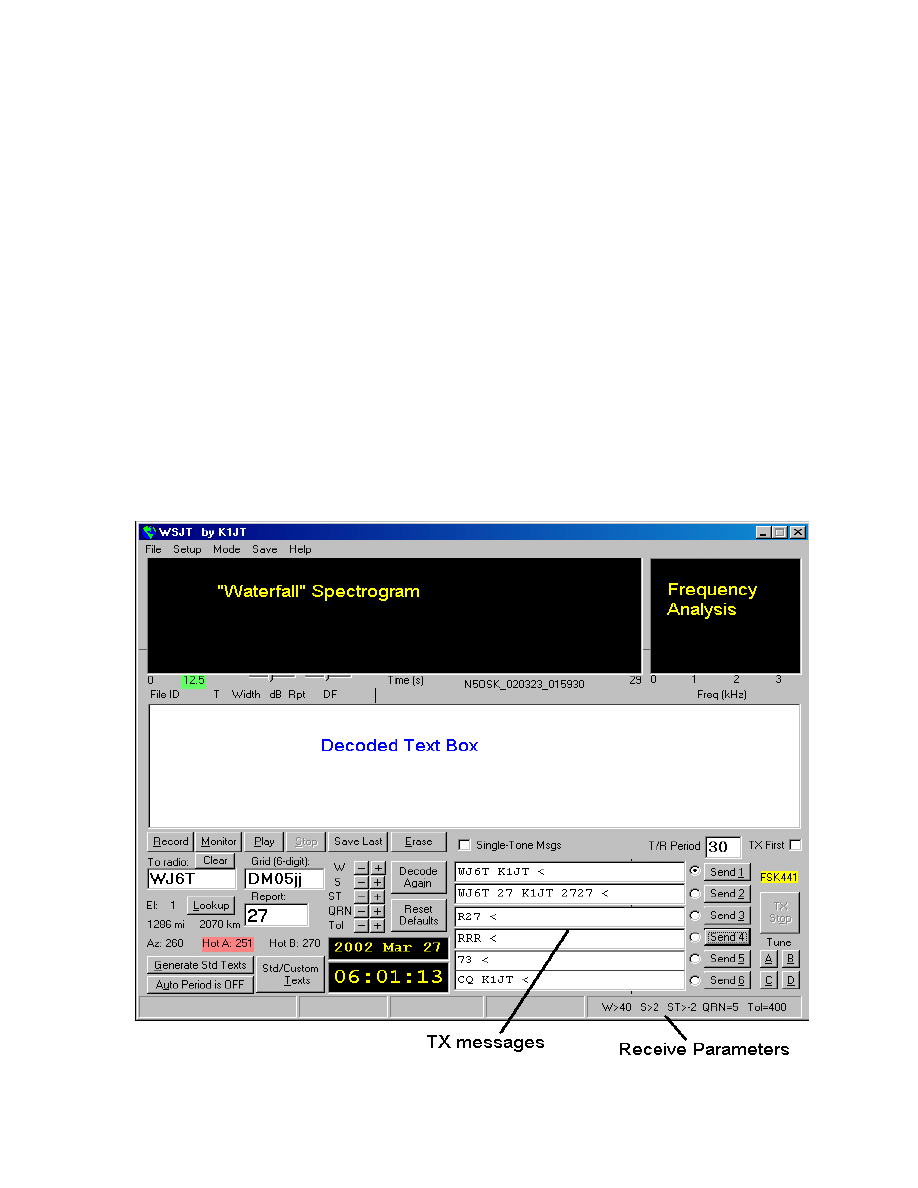
Decoded text from received signals appears in the white text box near the center
of the screen. As an example, a QSO between K1JT and K0SM might produce
lines of text like the following:
FileID T Width dB Rpt DF |
154000 15.0 260 8 26 -21 K1JT 27 K0SM 2727 *
154100 17.2 40 2 16 195 R3 1#
154500 6.7 100 5 26 -21 RRR 3
The first number on each line shows the start time of the recording in hhmmss
format. The second number shows the time of a detected ping relative to the
beginning of the file, in seconds. The third and fourth numbers give the duration
of the ping in milliseconds and its peak strength in dB, measured as (S+N)/N.
Column five suggests an appropriate signal report, and column six displays a
quantity called DF that measures the apparent frequency offset of the received
signal, in Hz. If one of the specially encoded single-tone messages has been
detected, it is listed next: R26, R27, RRR, or 73. The decoded text from a multi-
tone message comes last.
In the example above you can see that the first ping contained two callsigns and
a “27” signal report. The ping occurred at 15:40:15.0 UTC. It lasted 260 ms,
peaked at 8 dB above the noise, and was received 21 Hz lower than the
expected frequency. The signal received at 15:41:17.2 was a noise burst that
triggered the decoder. It is very short and contains no useful information. You
will soon learn to recognize such signals as QRN, rather than an actual meteor
ping, when you hear them. Even when they are very brief, legitimate FSK441
signals have a distinct “burbling” sound that is clearly different from the sound of
a static crash. Single-tone pings are easy to recognize by ear, as well. WSJT is
adept at distinguishing these different sounds, and will suppress text output from
most non-FSK441 signals. Occasionally the program will be fooled, however, by
birdies or QRN. With experience you will gain skill in making the necessary
distinctions yourself.
The ping at 15:45:06.7 was decoded as a single-tone “Roger” message. Notice
that the RRR appears in a separate column to the left of any multi-tone
messages.
The frequency resolution used in decoding multi-tone messages is about 43 Hz,
so reported frequency differences less than this magnitude are not significant.
11

WSJT will correctly receive FSK441 signals that are mistuned by 200 Hz or even
more, but retuning the receiver (or using the RIT) so as to reduce DF to
something smaller than 100 Hz is nevertheless desirable.
WSJT attempts to detect the inherently repetitive pattern of all multi-tone
transmissions. If the length of the periodic message is recognized, the program
will average over the available repetitions to improve copy. When this happens
you will see an asterisk (*) at the far right after the decoded text, as shown in the
example above. Single-tone decodings are accompanied by a number in the
same column, indicating the relative reliability of the detection on a 1–3 scale.
Mouse-Pick Feature
When the mouse pointer is moved inside the spectrogram area its horizontal
location is displayed numerically at the bottom left of the plot, in seconds.
Clicking the left mouse button inside the graphical area forces the program to
attempt decoding of whatever signal is present at that particular time. Clicking
the right mouse button will do the same thing, but with the message-averaging
feature disabled. When you are attempting to decode a marginal ping, try
clicking at several slightly different starting locations. Clicking with the mouse is
also useful for decoding steady signals that fail to trigger the ping detector
automatically.
Final Preparation for a QSO
Enter the desired length of the transmit and receive periods in seconds in the
T/R Period box on the main screen. Thirty (30) second periods have become
standard in most places, but other values are possible. Check the TX first box if
you wish to transmit during the first sequence. In North American meteor-scatter
work, by convention, the westernmost station transmits first in the T/R sequence;
other regions use different conventions. Enter the other station's callsign in the
To radio text box, and click on Generate Std Texts to create a sequence of the
most commonly used messages. You may edit the messages, if desired, and
you can also compose custom messages. To do so, toggle the Standard/
Custom Texts button and then edit any of the six text boxes provided. WSJT
will save your custom messages and restore them the next time you run the
program.
If you click on the button labeled Lookup, WSJT will attempt to find the specified
callsign in a database file CALLSIGN.TXT in the installation directory. This file
contains grid locators (and possibly other information) for each listed call. An
example file has been included with the program distribution, but you will
probably want to adapt it to your own region and extend it over time. (Edit the
file using Windows Notepad or another plain ASCII text editor; follow the formats
shown.) If the To radio callsign is found in the database file, the program will
copy the grid locator into the adjacent text box and use it to compute the
12

distance and bearing from your location to the other station. If the Lookup
request fails and you know the other station's grid locator, you may enter it by
hand. The full six-digit grid locator is preferable, but the four-digit locator
followed by a space will suffice.
In addition to the great circle bearing, the program will list the takeoff elevation
for reflections from meteor trails at 100 km height and the azimuths of statistical
“hot spots” on either side of the direct path. The hot spots are the directions that
provide the best geometry for reflections between the two specified locations at
the current time of day, assuming random meteor directions. The hot spot
highlighted in red is the most favorable one at the present time of day. Keep in
mind that during meteor showers the directions of meteor paths are anything but
random. Under those conditions the statistical hot spots do not apply.
Standard QSO Procedure
Completing contacts with WSJT becomes much more efficient if you follow
standard operating procedures. Seek out and read carefully some of the
relevant information on high-speed meteor scatter practices available on the
web, for example at the URLs www.qsl.net/w8wn/hscw/hscw.html and
www.meteorscatter.net/hsms.htm.
Very briefly stated, the standard North American message sequence for a
minimal meteor-scatter contact goes as follows:
1. If you have received less than both calls from the other station, send both
calls.
2. If you have received both calls, send both calls and a signal report.
3. If you have received both calls and a report, send R plus signal report.
4. If you have received R plus signal report, send RRR.
5. If you have received RRR — that is, a definite acknowledgment of all of
your information — the QSO is officially complete.
6. However, the other station may not know this, so it is conventional to send
73s (or some other conversational information) to signify you are done.
When you are ready to start an automated sequence of reception and
transmission periods, either to start a schedule or to call or answer a CQ, click
on the circle next to the desired TX message and toggle Auto Period On.
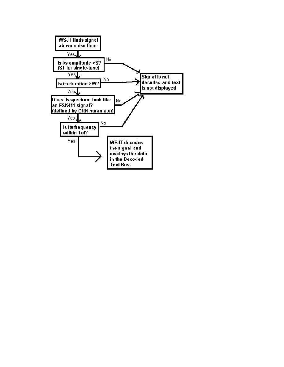
How WSJT Decodes an FSK441 Signal
When each receive period is finished, all pings above stated thresholds of width
W and strength S will be selected and decoded automatically. A separate
strength threshold, ST, is provided for pings carrying single-tone messages. All
three parameters can be set to their default values W=40 ms, S=2 dB, and ST=
13

2 dB by clicking the Reset Defaults button. Adjustments can be made at any
time by clicking on the + and – buttons next to the parameter labels.
The flowchart on the next page presents a simplified schematic description of the
process used by WSJT to decode an FSK441 signal.
Ping widths are measured and reported by WSJT in 20 ms increments. Note
that at the FSK441 transmission speed of 147 characters per second, a 20 ms
ping can contain only about three characters. Nevertheless, it is not unusual to
see WSJT correctly decode three or four characters from a 20 ms ping only 1 or
2 dB above the noise.
Single-tone messages are shorthand notations for certain frequently used parts
of meteor-scatter QSOs. Because of the narrower bandwidth that can be used in
the decoder, they provide a signal-to-noise ratio as much as 3 to 6 dB higher
than multi-tone messages. Setting the ST limit at –2 dB seems to be about right
for most conditions, and keeps the probability of false single-tone decodes quite
low. It would be wise, however, to gain some experience listening to WSJT’s
single-tone messages before blindly accepting their decodings. After gaining
some experience you may decide to set the ST threshold to even lower values
when you have reached the relevant part of a meteor-scatter QSO.
WSJT employs a QRN filter to distinguish between impulsive interference and
legitimate FSK441 signals. The QRN parameter can be set at levels from 1 to
10, with the default value being 5. In a noisy environment, such as when your
antenna is pointed at a distant thunderstorm, static crashes can accidentally fool
the decoder into displaying garbage text. Setting the QRN value higher will help
to filter out this noise. However, a higher QRN value makes the program less
sensitive to weak or slightly mistuned signals. In a quiet environment, QRN=3
may be a logical choice.
14
WSJT attempts to compensate for relative mistuning between the transmitting
and receiving stations. However, mistuning by more than about 200 Hz will
generally cause the decoding accuracy to deteriorate. For every decoded ping
the program lists its best estimate of frequency offset in the DF column. The
accuracy of these estimates is approximately ±22 Hz for multi-tone FSK441
signals, and somewhat better for single-tone pings. Within these tolerances, you
should see consistent numbers in the DF column during a QSO that is producing
usable signals.
If the DF value lies outside the range ±100 Hz, it will probably help to retune your
receiver to compensate. For example, if you see DF values for correctly
decoded text at –280 Hz — or if you observe that the red spectral curve for a
strong ping seems to be displaced significantly to the left and the ping has not
decoded properly — tune your receiver lower in frequency by the appropriate
amount. Do this with your RIT control, or by using split T/R mode if your radio
has such a feature. In general you will want your transmitted frequency to
remain constant, since your QSO partner will be trying to tune in your own signal
at the same time. You do not want to confuse him/her by moving your frequency
around!
Note that if the relative tuning of transmitter and receiver is offset by an amount
approaching 441 Hz, the FSK441 inter-tone spacing, a peculiar situation can
arise in which DF is reported to be close to zero and yet decoding fails. Such a
15

circumstance will be recognizable by the evident displacement of the red spectral
curve to the left or right, so that a whole tone seems to be missing. Retune the
receiver to bring the received FSK441 spectrum for subsequent pings into proper
registration.
You can narrow the range of frequencies to be searched by reducing the value of
Tol (for “tolerance”) from its default maximum value of 400 Hz. If you have
clearly identified the frequency at which you are receiving your QSO partner,
setting Tol to a lower value such as 100 Hz will significantly reduce any on-
screen gibberish from falsely decoded noise bursts. In such a circumstance it is
often safe to reduce the other threshold parameters to smaller values, say W=20
ms, S=1 dB, ST=–5 dB, to finish your QSO. You have effectively “locked onto”
your partner's signal.
After adjustments have been made to one or more of the decoding parameters,
clicking Decode Again will trigger reprocessing of the entire received file. As
always, right- or left-clicking with the mouse pointer on a particular signal feature
with trigger decoding of the signal under the pointer.
Whatever values are selected for the threshold limits for pings, you are likely to
see some errors in the decoded messages, especially near the beginnings and
ends of pings where the signal fades up from and back into the noise. Of
course, comparable uncertainties occur with CW or any other mode of
communication when signals are marginal. Unlike some digital modes that
require high accuracy and therefore employ error-correcting schemes, the design
criteria for FSK441 willingly relax accuracy requirements in order to gain speed.
The necessary accuracy is achieved by means of repetition and operator skill.
On-Screen Controls
Auto Period ON/OFF toggles on and off the timed sequencing of transmit and
receive periods. During a schedule, you and your partner alternate so that only
one station is transmitting at any time. The duration of each RX or TX interval is
set by the T/R Period parameter.
Brightness adjusts the brightness of the waterfall spectrogram. Click Decode
Again to see the effect of a change.
Contrast adjusts the contrast of the waterfall spectrogram.
Decode Again causes the last recorded or opened file to be decoded once
more, perhaps after one or more decoding or display parameters have been
changed.
Erase will delete all information in the decoded text box and the graphical areas.
16

Generate Std Texts will create standard messages used in FSK441 QSOs by
using information in the My call, To radio, and Report text boxes. The standard
format of the messages is slightly different depending upon your IARU region
(see NA Defaults and EU Defaults under the Setup | Options menu item.)
This button will also reset the TX message number to 1 and the Tol parameter to
400 Hz.
Lookup causes the program to search the callsign data base for the entry in the
To radio box. If that callsign is found, the station's grid locator will be retrieved
and used to calculate distance and azimuth.
Monitor causes WSJT to make an extended series of recordings, perhaps to
monitor a calling frequency or to copy two other stations engaged in a QSO.
Recording is continuous except for small gaps between the timed receiving
periods. Decoded text will be displayed in the usual way after each recording is
finished.
Play. This control plays a recorded file through the sound card speaker output. It
functions much like the “Play” button on a cassette recorder.
QRN. Setting the QRN parameter to higher values will help to suppress false
decodings caused by atmospheric noise, but also makes the program less
sensitive to weak or slightly mistuned signals. The default value is 5.
Record. This button starts a recording of audio from the radio. The program will
record for the time entered in the T/R Period box or until you press the Stop
button. (If Auto Period On is set, recording will stop at the end of the present
T/R interval.) When a recording in finished, it will be plotted and decoded. This
control works much like the “Record” button on a cassette recorder.
Reset Defaults will reset the decoding parameters (W, S, ST, QRN and Tol) to
their default values.
S sets the minimum increase in signal that will be accepted as a multi-tone ping.
If S is set at 2 dB, WSJT will attempt to decode signals that are 2 dB or more
above the noise floor and last longer than the limit set by the W parameter.
Setting S to a lower value will trigger the decoding of weaker signals, but will
probably also display more false signals. Adjustments are made with the + and –
buttons. You can see the current settings in the status bar at the bottom right of
the WSJT screen.
Save Last. Clicking this button will prevent the most recently recorded file from
being deleted at the start of the next recording.
Send 1 – 6. Pressing these buttons activates the transmitter. The specified
message will be sent until the end of the present TX sequence or, if Auto Period
17

is Off, for the duration listed in the T/R Period box. The message background
becomes colored to remind the operator which message is being transmitted.
Yellow backgrounds denote multi-tone messages, while light blue backgrounds
signify single-tone messages.
Single-Tone Messages. Check this box to enable the transmission of single-
tone shorthand messages for R26, R27, RRR, and 73. The single-tone
messages are very effective for completing QSOs when pings are weak and
infrequent and QRM is not a problem.
ST sets the minimum strength of a single-tone signal that WSJT will attempt to
decode. It works in much the same way as the parameter S does for multi-tone
signals, and allows even weaker signals to be successfully decoded. The
current value of ST is displayed in the status bar at the bottom right of the WSJT
form.
Standard Texts / Custom Texts permits you to toggle between two sets of TX
messages. The standard texts are those most commonly used in meteor-scatter
QSOs; custom texts can be used to store other messages such as grid square or
contest information. Custom messages will be saved when you exit WSJT and
restored when you next start the program.
Stop terminates a Record, Monitor, or Play operation. It functions much like
the “Stop” button on a cassette recorder.
Tol sets the bandwidth or “tolerance” of a software filter. WSJT will not present
decodings for signals it judges to be mistuned by more than this number of Hz.
By default Tol is set to its maximum value, 400 Hz, and you should normally
leave it there until the frequency offset of the other station has been determined.
When DF has been established and reduced to a small value by retuning the
receiver, you may decrease the value of Tol to reduce the probability of false
decodings. The current value of Tol is displayed in the status bar at the bottom
right of the WSJT form.
Tune A, B, C, D. These buttons cause steady tones to be generated at one of
the four standard FSK441 frequencies. Use them to adjust your transmit audio
level, tune your amplifier, adjust your automatic level control (ALC) setting, etc.
TX First should be checked if you wish to transmit during the first period of the
timed T/R sequence. Uncheck it if your schedule partner is transmitting in the
first period. In North America the convention for meteor-scatter work is for the
westernmost station to transmit first. In the rest of the world, the easternmost
station usually transmits first.
18

TX Stop will interrupt a transmission in progress. It will not toggle Auto Period
Off, however. To prevent another transmission from starting, press TX Stop and
then toggle Auto Period Off.
W sets the minimum width of impulsive signals that will be considered for
message decoding. Use the + and – buttons to adjust the value of W. You can
see the current setting in the status bar at the bottom right of the screen
Text Boxes
Decoded Text. This box is the large area in the center of the program window.
It displays decoded text and other useful information, allocating one line per ping.
A scrollbar appears if the number of lines exceeds the window height. You
cannot edit text in this window. However you can highlight text, copy it to the
Windows clipboard by typing CTRL-C, and then paste the text elsewhere by
using CTRL-V.
Grid. After you have pressed Lookup, this box will display the grid locator of the
station in the To radio box if that station is found in the callsign database. You
may also enter a grid locator manually.
Report. Enter the signal report you wish to send to the other station, then click
on Generate Std Texts to create the standard messages. In FSK441, as well as
in HSCW, operators use a two-number reporting system that is different from the
“RST” system. Be aware that Generate Std Texts resets the active Tx message
to #1 and Tol to 400 Hz.
Status Bar. This strip along the bottom of the program window provides panels
for displaying useful information such as file name, file position, RX audio level,
and decoding parameters.
To radio should contain the callsign of the station being called or worked. Text
entered in this box will become the first part of the filename when a recording
begins.
T/R Period sets the length of automatic transmitting and receiving intervals, in
seconds.
19
Operating in JT44 Mode
How JT44 Works
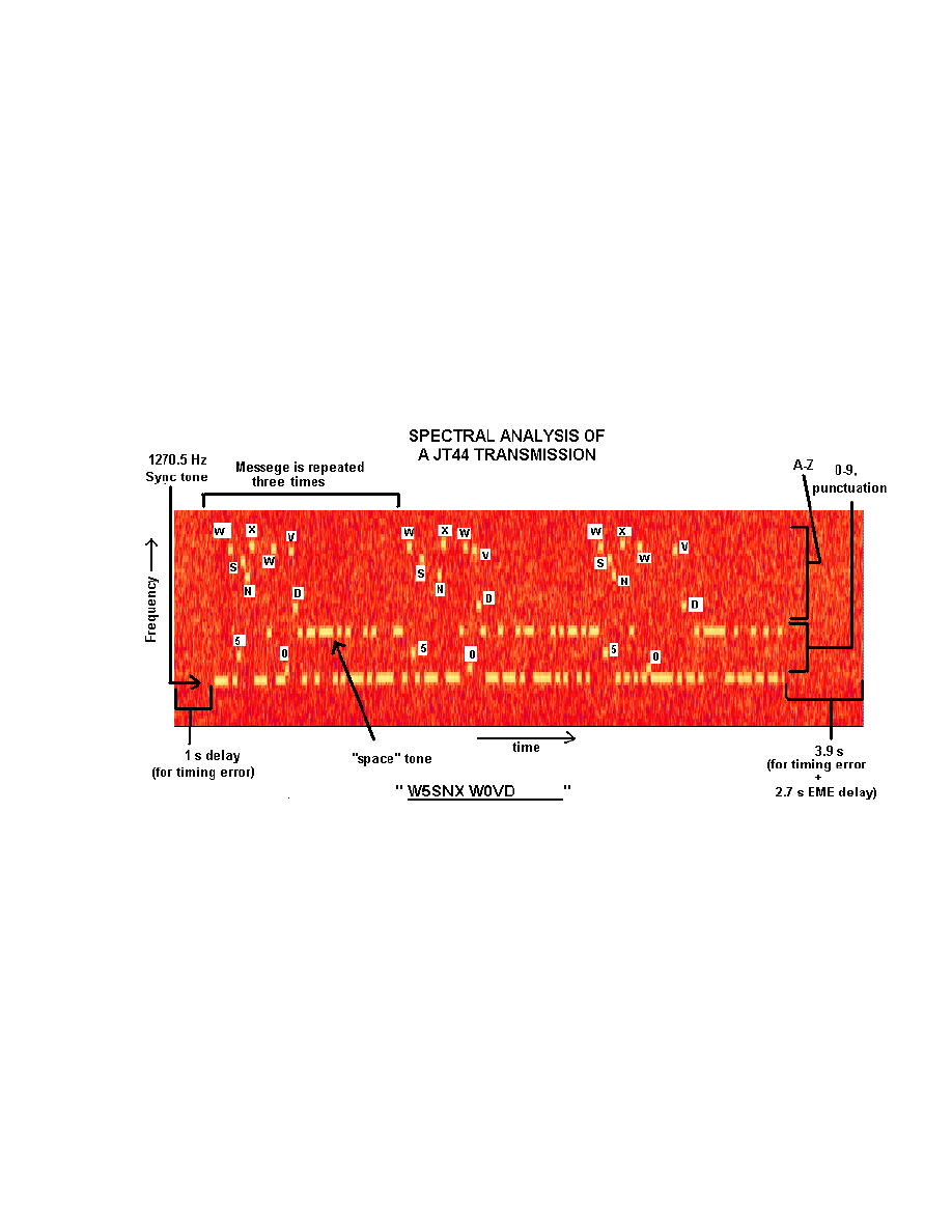
The JT44 message format involves 135 intervals of data transmission, each
about 0.186 sec in length. Of these, 69 intervals carry a synchronizing tone at
1270.5 Hz. The other 66 intervals carry a 22-character message, repeated three
times. Each of 43 supported characters is assigned a unique tone in the
frequency range 1302.8 to 1755.0 Hz. Proper message transfer depends on
achieving synchronization between transmitter and receiver, and for this purpose
it is desirable to have your computer’s clock set to UTC with an accuracy of one
second or better.
The figure above shows a time vs. frequency spectrogram of an audible JT44
signal (about +10 dB S/N in a 2500 Hz bandwidth). Transmit audio starts 1.0
second into the TX interval and lasts for 135 intervals, or about 25.08 seconds.
The final 3.92 seconds (minus necessary relay switching time, etc.) of the
transmit period may in future be used for a fast station identification in voice or
CW, but this feature has not yet been implemented. The idle time also serves to
accommodate EME propagation delays and possible clock offsets between you
and your QSO partner.
When WSJT finishes a recording, it analyzes the file for a sync tone. It looks for
the best S/N ratio of a tone with the prescribed on-off pattern, as illustrated in the
spectrogram above (see also the Appendix). For this search the program scans
20
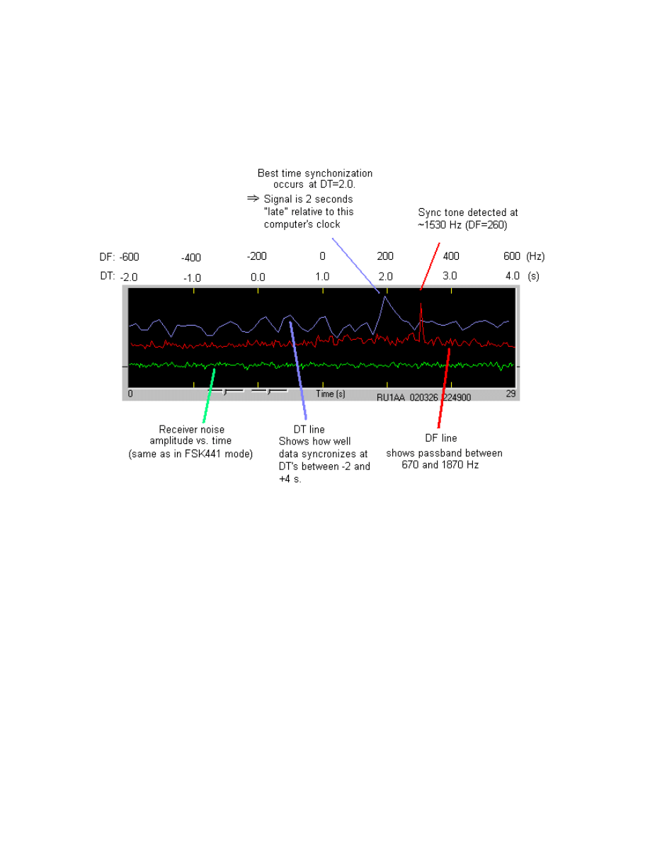
a ±600 Hz frequency range and time offsets from –2.0 to +4.0 seconds.
Graphical details on the attempts at time and frequency synchronization are
presented in the display area at the top of the program window, as illustrated
below.
Once WSJT has determined the frequency and time offsets DF and DT, it
attempts to recover the 22-character message. On average, single letters in the
message will have poorer signal-to-noise ratio than that of the sync tone by 6.8
dB. This is because much less time is spent sending each particular letter, and
therefore less signal energy is present at any particular character’s frequency.
However, averaging the received character-tone spectra over many 30-second
reception periods can make up that loss. For such incoherent averaging, each
doubling of the number of periods adds 1.5 dB in S/N. Four periods gets you 3
dB improvement, 16 periods gets 6 dB, and so on. If the signal strength is fairly
steady and the sync-tone remains detectable, you can get good copy of a
message in about 15 to 20 minutes.
The cost of using about half of the transmission time for the sync tone is 1.5 dB,
and this seems to be a very good compromise in practice. It means that
transmissions can be synchronized at the receive end even when the S/N is –28
or –29 dB relative to the background noise in a 2500 Hz bandwidth. Note that,
by comparison, the minimum CW signal strength that can be copied is about –11
21
dB relative to same noise level, or equivalently +6 dB in a 50 Hz bandwidth.
JT44 can present solid copy with signal levels well below those required for
conventional CW.
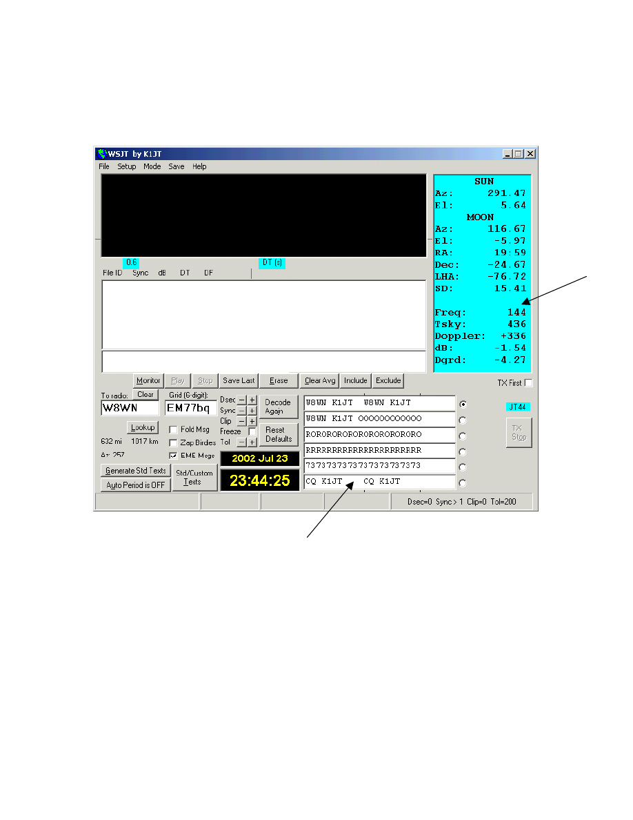
Graphics Window
Decoded Text Box
Average Text Box
Sun/Moon
Data
TX Messages
Receiving JT44
JT44 transmissions cannot be decoded unless the transmitter and receiver are
synchronized. As a consequence, the only means provided for transmitting or
receiving is by triggering Auto Period On. Just as in FSK441 mode, WSJT
analyzes a recorded JT44 signal after a receiving sequence has been
completed. A graphical display is presented and decoded text, if any, is
displayed in the text boxes near the center of the screen.
To monitor both the first half and second half of each minute for JT44 signals,
click the Monitor command. WSJT will accumulate separate average messages
for the first and second transmitting sequence, so that you can “read the mail”
22

and follow the progress of another QSO. To monitor just one side of a contact
you may also check Setup | TX Mute (or use shortcut F3) and then toggle Auto
period On. The effect is as if you were in a QSO with another station, except
that you will not actually transmit.
Decoded Text
JT44 provides two separate boxes for decoded text. The larger one displays a
line of new information after each receive cycle. A typical line produced by a
relatively “strong” signal — i.e., one barely above the threshold of audibility —
might look like the following:
FileID Sync dB DT DF |
194300 3 -11 -0.2 12 * K0SM K1JT K0SM K1JT
The File ID column displays the UTC start time of the reception interval, in this
case 19:43:00. These six digits also serve as the trailing portion of the name of
the wave file stored on disk. The numerical parameter labeled “Sync” provides
a measure of confidence that the message has been properly synchronized, on a
nonlinear 0 to 10 scale. Values of 1 or above usually indicate valid
synchronization. Next comes a measure of the signal strength, measured in dB
relative to the noise in the full receiver passband, typically about 2500 Hz. (The
strength of signals well above the audible threshold will generally be
underestimated.) DT measures the time offset of a received message relative to
your computer’s clock. If both station’s clocks are accurately set, DT should be
approximately 0.0 s for terrestrial QSOs and 2.5 s for EME QSOs. Finally, the
parameter DF presents a measure of the frequency offset of the received signal,
in Hz, relative to your own radio’s dial setting. In normal operation WSJT
searches for the synchronizing signal over a frequency range –600 to +600 Hz
and over time delays from –2.0 to +4.0 s.
Most JT44 operation involves signals that are very weak. The weakest
synchronizable signals will not display good copy on a single transmission; for
steady levels down to about –28 or –29 dB, the program will generally be able to
achieve synchronization but will correctly decode no more than a few characters
in the message. For each transmission that is above the user-settable “Sync”
threshold (by default set to S=1), WSJT accumulates an “average message” and
displays it in the smaller text box near center screen. Each message included in
the average is marked with an asterisk (*) after the DF column. In this way,
WSJT can build up the message from a number of successive receive intervals.
The illustration on the next page shows text received by GM4JJJ during a 144
MHz EME QSO with K1JT. Notice that none of the four reception periods gave
usable copy, but averaging them together reproduced the message perfectly.
23
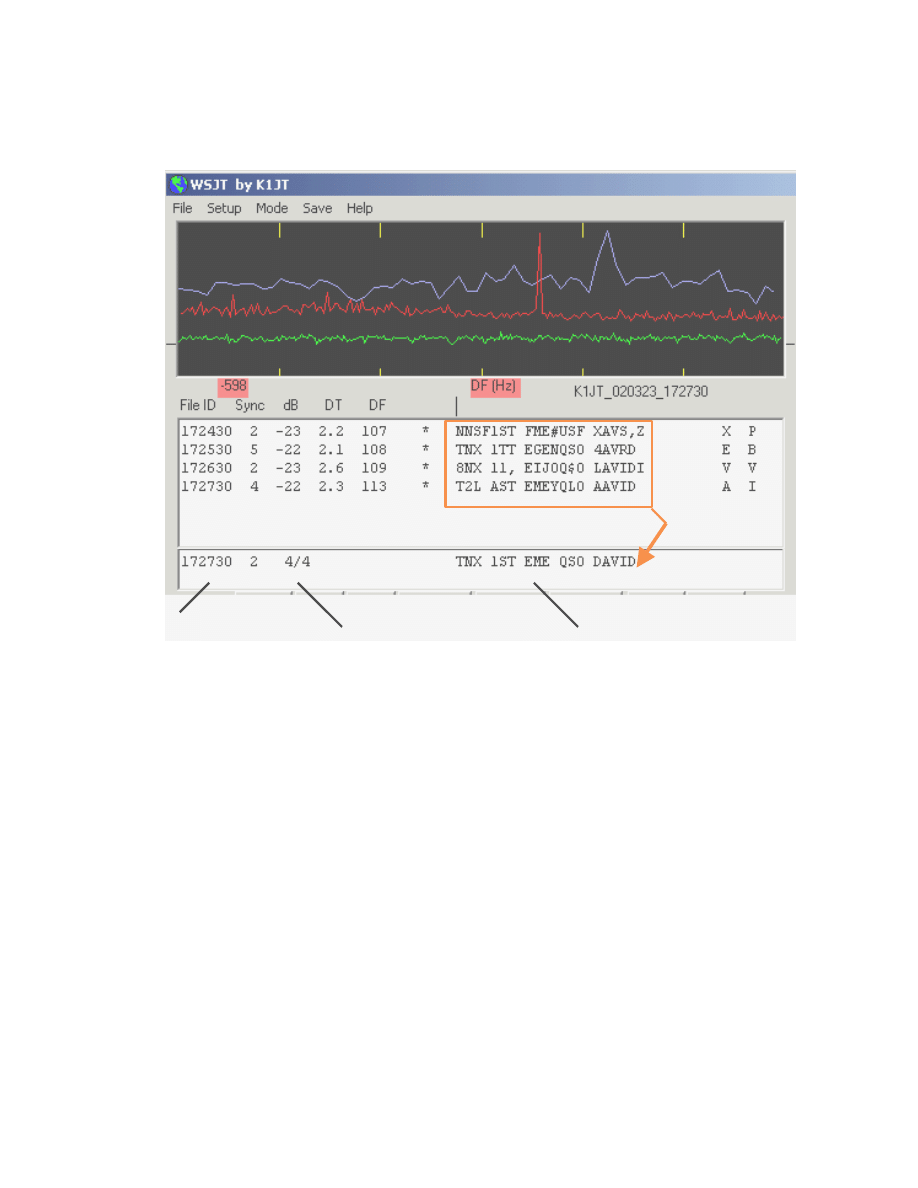
The latest recording is displayed in the graphical display, while all of them are
listed in the main text box.
Time
# recordings included
/ # total recordings
Average text
Sometimes a signal will fade below the synchronizing threshold or interference
will cause the program to find an incorrect DF or DT. If you are sure the program
made an error you can press the Exclude button to remove the most recent
recording from the accumulating average. Similarly, the Include button will
include the latest file in the average even if it failed to exceed the Sync threshold.
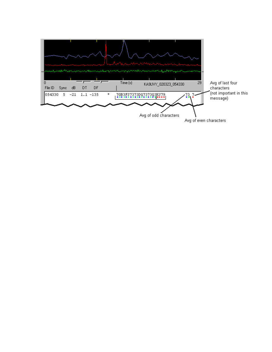
In addition to message averaging over a number of receive periods, WSJT offers
several forms of averaging within each period. Three extra characters at the far
right accompany each decoded JT44 message. These characters represent the
average of the odd, even, and last N characters of the message, where N is the
number of repeated characters at the trailing end of standard message #2.
Messages with repetitive content (see “Message Formats” below for examples)
can gain up to 5.4 dB in signal-to-noise ratio by such intra-message averaging.
In addition, by checking the box labeled Fold Msg you can instruct the program
to average the first and second halves of the 22-character message. This
procedure can yield 1.5 dB in added sensitivity for exactly repeated 11-character
messages.
24
Birdies
“Birdies” are low-power RF signals that can appear as steady carriers, drifting
carriers, pulsing signals, or “noise” over a few kHz of spectrum. Computers and
computer monitors can be sources of birdies, as can handheld electronic games,
coffee makers, and even your own transceiver. No matter where you choose to
operate, you will probably find birdies. When choosing a schedule frequency, it
helps to listen first to ensure that the frequency is clear of birdies.
Because of its long-term signal averaging techniques, the JT44 mode can detect
birdies that are impossible to hear by listening to the receiver audio. Birdies may
appear as spikes in the red graphical display, thus giving the false impression of
a detected sync tone. Running a JT44 schedule on a frequency close to one or
more birdies can cause the program to confuse the sync tone and the birdie or to
decode the birdie as spurious text. Although it is best to operate on clear
frequencies, it is sometimes impossible to evade a birdie that appears in the
middle of a QSO. The following illustration is an example of what can happen if
a birdie appears in the passband together with a valid JT44 signal.
25
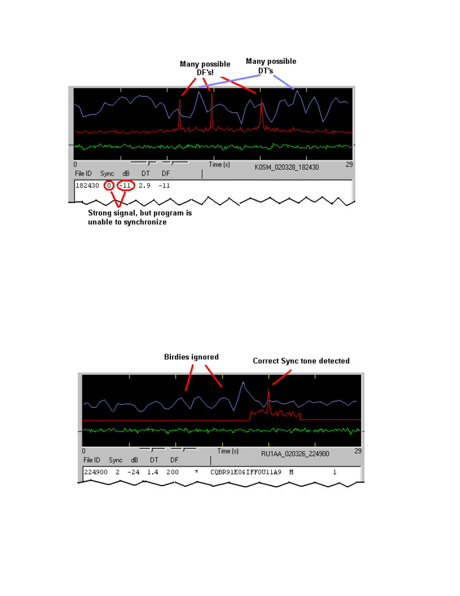
In the figure above, the red curve shows birdies at DF = –150 and DF = –11,
while the valid sync tone is at DF = +201 Hz. The program chose the signal at
DF = –11 because it was the strongest. Notice that the program had trouble
finding the proper DT for this signal, since a carrier with slightly wavering
amplitude may fit the pseudo-random timing pattern well at many DT’s, creating
a jagged blue line with many peaks. Although the signal is relatively strong, the
program was unable to find an acceptable sync value (Sync=0), and no text was
displayed.
Once the program detects a JT44 signal so that you see some recognizable text,
you may click with the mouse on the appropriate spike in the red curve and then
26

check Freeze. Then press Decode Again, and WSJT will search only a small
range of frequencies around the selected DF. The range to be searched is
determined by the Tol parameter. The illustration above shows a recording
similar to the one in the previous figure, but this time Freeze was checked and
Tol set to 100 Hz. Notice that birdies outside of the 100 Hz window have been
ignored. The Sync value has increased to 2 (almost always enough to signify
good synchronization) and some text is displayed: RU1AA was calling CQ off the
moon in this example. You may set the Tol parameter as low as 25 Hz, but keep
in mind that EME Doppler shifts change slowly and some radios drift gradually
over time.
Version 2.2 of WSJT introduced a new checkbox labeled Zap Birdies. By
checking this box you will instruct the decoder to ignore narrow-bandwidth
signals that remain on during the JT44 sync-tone intervals. In many instances
this can improve your copy of a JT44 signal in the presence of birdies falling in
the signal passband, which extends upward from the sync tone by 495 Hz. The
birdies will still appear in the displayed red curve, so that you can keep track of
them. To gain some feeling for how this feature behaves, try opening the
example file W7FG_020320_041300.WAV and processing it both with and
without Zap Birdies checked.
Standard Message Formats
Transmit and receive periods in JT44 mode are always a nominal 30 seconds
long, starting on UTC half-minutes. Messages are 22 characters in length. If
you enter a message shorter than 22 characters, the remainder will be filled with
spaces; if you enter more than 22 characters, only the first 22 will be sent.
Because of the tight synchronization requirements of JT44, you cannot change
messages while transmitting. However, at any time you may pre-select the next
message that will be sent. You may edit messages at any time, except for the
one actually being transmitted.
WSJT supports two standard message formats in JT44 mode. Either format is
valid for a QSO, regardless of the mode of propagation. Indeed, many other
possible formats would also be perfectly valid. It is helpful, however, to adopt
some standards, and important that you use them correctly to exchange the
necessary information for a valid QSO. Both stations must receive complete
callsigns, a piece of information (grid locator, signal report, etc.), and a “Roger”.
You can switch between the two standard message formats by checking or
unchecking the EME Msgs box and then clicking the Generate Std Texts
button. Notice that the repetitive nature of these messages allows the program
usefully to average the “odd”, “even”, and “last N” characters, as well as the first
and second halves of the message, as possible aids for message decoding.
27

Tropo/Ionoscatter: (“EME Msgs” not checked)
1. K0SM K1JT FN20
2. K0SM K1JT FN20 RRRRRRR
3. RRRRRRRRRRRRRRRRRRRRRR
4. 7373737373737373737373
5. (empty, user defined)
6. CQ K1JT CQ K1JT
EME: (“EME Msgs” checked)
1. K0SM K1JT K0SM K1JT
2. K0SM K1JT OOOOOOOOOOOO
3. RORORORORORORORORORORO
4. RRRRRRRRRRRRRRRRRRRRRR
5. 7373737373737373737373
6. CQ K1JT CQ K1JT
Practical Operating Hints
The secret of successful JT44 communication is making sure that frequency and
time synchronization are achieved. Be sure that you know your frequency
calibration well enough to be within a few hundred Hz of the intended frequency.
The receiving operator should adjust his or her RIT to account for the expected
Doppler shift on EME paths, especially at frequencies higher than 144 MHz. Be
sure to keep your Windows clock set to within one second or better. For
terrestrial QSOs the outer limit for clock errors that will still provide good copy at
both ends is ±2.0 seconds. (If each station has a 1.1 second setting error and
they are in opposite directions, sync attempts in at least one direction will surely
fail.) You should aim to have WSJT find values of DT in the range –1.0 to +1.0
seconds for terrestrial contacts. The EME path adds about 2.5 seconds of
propagation delay, and since the maximum DT allowed by WSJT is 4.0 s, the
outer limit for acceptable clock offsets is reduced from 2.0 to about 1.5 s. You
should aim to have DT in the range 1.7 to 3.3 seconds for EME QSOs, with
absolute outer limits of 1.0 to 4.0 seconds.
On-Screen Controls
Auto Period ON/OFF toggles the timed T/R sequencing on and off. During a
schedule, you and your partner alternate so that only one station is transmitting
at any time. If you only wish to listen, disable the transmitter by toggling F3 or by
checking the Setup | TX mute menu item.
Clear Avg. Clicking this button erases text in the smaller text box and clears the
average message accumulators. Use this command when the other station has
28

started to send a new message, or when the average contains no useful
information.
Clip is set by default to zero. If you increase its value to 1, 2, or 3, the program
will apply “soft,” “moderate,” or “hard” clipping to the signal before attempting to
decode the message. Use this feature to reduce the effect of static crashes,
meteor pings, or other brief signal enhancements. It will often recover the
program’s ability to synchronize on a weak residual JT44 signal.
Decode Again causes the last open file to be decoded once more, perhaps after
parameters have been changed or Clear Avg has been executed.
Dsec is a clock offset parameter, measured in seconds. Its value (displayed in
the status-bar panel at the lower right) is added to the time kept by Windows to
establish the UTC displayed and used by WSJT. You can use it to make small
clock adjustments when necessary. In general, however, it is best to keep the
computer clock set accurately and Dsec set to zero.
EME Msgs. Checking this box will change the standard message formats to
ones like those generally used in CW EME communication. Many operators will
be more comfortable using this style of message, although it can require an
additional exchange to complete the QSO. After checking or unchecking this
box, press Generate Std Texts to create the desired messages.
Erase deletes all information in the decoded text box and the graphical display
area. Information in the average text box will be retained, however.
Exclude will remove the most recent recording from the average message. Use
this option when you are sure that the program has synchronized incorrectly and
you wish to avoid contaminating the average message with bad data.
Fold Msg. Check this box to gain an average of 1.5 dB in sensitivity for a JT44
message that is identical in its first 11 and last 11 characters.
Freeze. Check this box when the DF of the other station has been clearly
established and you want WSJT to search only frequencies near that value in
subsequent receive periods. The target DF is set by clicking with the mouse,
and the extent of the search range is determined by the adjustable Tol
parameter.
Generate Std Texts triggers generation of the standard messages used in JT44
mode. The messages will use the information you have entered in the My call
and To radio text boxes. This button will also reset the TX message number to
1 and the Tol parameter to 200 Hz. The standard format of the messages can be
changed by first checking or unchecking the EME Msgs box.
29

Include will include the most recent recording in the average message if the
signal level was greater than –32 dB, even if the Sync value is below the
threshold determined by the S parameter.
Lookup causes the program to search the CALLSIGN.TXT file for the callsign in
the To radio box. If the callsign is found, the station's grid locator will be
retrieved and the distance and great circle azimuth bearing will be displayed.
Play. This control plays a recorded file through the sound card output port. It
functions much like the “Play” button on a cassette recorder.
Reset Defaults will reset the parameters S, Clip, and Tol to their default values.
S sets the “Sync” threshold for the JT44 decoder. The higher this value is set,
the less chance of the decoder incorrectly interpreting a signal. Higher values
will not allow very weak signals to be decoded. The default value is 1.
Save Last. Clicking this button will prevent the most recently recorded file from
being deleted at the start of the next recording. (See also the menu item Save |
Save all.)
Standard/Custom Texts permits you to toggle between two distinct sets of TX
messages. The standard texts are those most commonly used in JT44 QSOs;
custom texts can be used to store other messages such as name or contest
information. Custom messages will be saved when you exit WSJT and restored
when you next start the program.
Stop will stop a recording in progress. It functions much like the “Stop” button on
a cassette recorder.
Tol sets the range of frequency offsets that WSJT will search to find the
synchronizing tone. Tol is activate only when the Freeze box is checked. When
the correct offset has been established and set by clicking witth the mouse, you
may decrease the value of Tol to reduce the probability of false decodings. The
range of Tol is adjustable from 25 to 200 Hz.
TX First should be checked if you wish to transmit during the first 30 seconds of
each minute. Uncheck it if your schedule partner is transmitting in the first
period. QSOs are very difficult to complete if both stations transmit at the same
time!
TX Stop will interrupt a transmission in progress. It will not toggle Auto Period
Off, however. To prevent another transmission from starting, press TX Stop and
toggle Auto Period Off. Once you stop a transmission you cannot start it again.
30

Zap Birdies. Check this box if you have problems with persistent narrow-band
interference in the first 500 Hz above a received JT44 sync tone. It will help if
you have already identified the correct sync tone frequency and checked the
Freeze box.
Text Boxes
Average Text. This box contains the average text from all previous receive
periods (or since “Clear Average” was pressed). It displays the time of the last
file added, the number of files added / total files received, and the program’s best
estimate of the averaged message.
Decoded Text. This box is the larger text area near the center of the WSJT
form. Each line displays the start time of the receive period, the “Sync” value for
that recording, the relative strength of the signal in dB, the time offset DT of the
received signal relative to your computer’s clock, the frequency offset DF of the
signal, and the decoded text. At the end of the decoded text there may appear
intra-message averages for the “odd”, “even”, and “last N” characters of the
message. You cannot edit text in this window, but you can copy it onto the
Windows clipboad by highlighting it and typing CTRL-C, and then paste it
elsewhere by using CTRL-V.
Grid. After a successful Lookup, this box will display the six-digit grid locator of
the callsign in the To radio box. You may also enter a grid locator manually. If
only four digits of the locator are known, add a space.
Status Bar. This strip along the bottom of the program window provides panels
for displaying useful information such as file name, file position, RX audio level,
and the decoding parameters.
To radio should contain the callsign of the station being called or worked. Text
entered in this box becomes the first part of the filename when a recording starts.
31

Menus
File |
Open allows you to read back a previously recorded file stored on disk.
The file must be a standard wave file recorded in 8-bit monaural format
with 11025 Hz sampling.
Delete files in RxWav will cause WSJT to delete all *.WAV files in the
RxWav subdirectory. You will be asked for confirmation before the
deletions are carried out.
Save text in file DECODED.CUM will cause all decoded text to be
appended to a file named DECODED.CUM in the WSJT installation
directory. If the file is not already present, the program will create it.
Delete file DECODED.CUM will delete the cumulative text file so that you
can start it afresh.
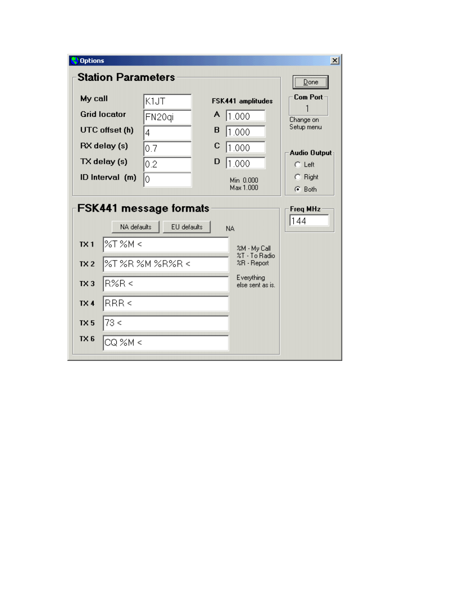
Setup |
Options
My call. Enter your callsign in this box.
Grid locator. Enter your 6-digit grid locator.
UTC offset. If your computer clock is not set to UTC, use this
option to offset the WSJT clock by the appropriate number of
hours. If you are east of Greenwich, enter a negative value.
RX delay will enforce a specified minimum delay between the end
of a transmission and the start of the next recording. The usual
purpose is to avoid dropouts and spikes created by amplifier
switching transients.
32
TX delay enforces a specified minimum delay between activation
of the PTT line and the start of the first audio tone sent to the
transmitter. This delay can protect antenna relays and mast-
mounted pre-amplifiers from transmitted RF during the changeover
time.
ID Interval sets the time between automatic station identifications
in FSK441 mode. To use this feature you must provide an audio
file named ID.WAV in the WSJT installation directory. The file may
identify your station identification using any desired mode, e.g.,
voice or CW. A CW identification should be recorded as a keyed
sidetone, preferably at about 440 Hz. A value of zero disables the
automatic identification. Automatic station identification is not
currently provided in JT44 mode.
33

NA/EU Defaults. These buttons establish the default style
templates used to create messages when you push the Generate
Std Texts button in FSK441 mode. Because there are different
meteor scatter operating procedures in different IARU regions,
WSJT is programmed to automatically create standard messages
suitable for both North American and European operators. Users
in other parts of the world should decide collectively what format
they wish to use. The templates may be edited, for example to
automatically append “/P” or another suffix or prefix to a callsign, or
to insert your grid locator as part of a contest exchange.
FSK441 Amplitudes. If necessary, use these boxes to adjust the
relative strength of each FSK441 tone. See the section on “Setting
the TX Audio Level” for more information. Level adjustment of
different tones is not currently supported in JT44 mode.
Audio output. You may select which stereo channel carries the TX
audio from the sound card to the radio: Left, Right, or Both.
Freq MHz. Enter the nominal frequency in MHz of the band you are
operating. The entry affects the Doppler shifts and sky background
temperatures displayed in the Sun/Moon display data area when
operating in JT44 mode.
Set COM port allows you to select which COM port will activate T/R
switching. Enter the number of the desired port. If you do not want the
computer to control T/R switching, enter “0”.
DTR, RTS. These are the names of two signal lines in the serial port. You
may select either or both of them to activate your station's T/R switching
sequence. Plans for a very simple controller interface may be found at
www.qsl.net/k0sm/interface.gif.
Adjust RX/TX Volume controls. Clicking on these menu items will cause
the sound mixer volume controls to be displayed for adjustment.
Alternate graphical pointer. The mouse pointer in FSK441 mode
becomes a “crosshairs” pointer when placed over the graphical area.
When this item is checked, the pointer will always be an “arrow”.
34

Mode |
WSJT currently supports two signaling modes: FSK441 and JT44. Use
this menu (or the shortcut keys F7 and F8) to switch between modes. (A
planned mode for EME self-echo tests has not yet been implemented in
WSJT Version 2.2.)
Save |
Save All. Checking this item will cause all recorded files to be saved in
subdirectory RxWav under your main WSJT installation directory.
Help |
Help displays a brief message urging you to download and read the
WSJT User’s Guide and Reference Manual (the manual you are reading
now).
About WSJT displays version and copyright information. On some
Windows installations the “System Info” button will also display
information about your computer and its operating system.
35

Appendix: Specifications of the Signal Protocols
FSK441
FSK441 uses four-tone frequency shift keying at 441 baud. The frequencies of
the audio tones are 882, 1323, 1764, and 2205 Hz. Each encoded character
uses three tone intervals and therefore requires 3/441 seconds (approximately
2.3 ms) for transmission. FSK441 accommodates an alphabet of 43 characters,
the same ones used in the PUA43 system developed by Robert Larkin, W7PUA.
Character encoding is defined in the table reproduced below. The four tones
have been labeled 0 – 3 for the tones 882 through 2205 Hz, in increasing order.
As an example, the letter “T” is transmitted by sending tones at 1764, 1323, and
882 Hz. Note that the character “space” is encoded as 033, and that three-tone
sequences starting with the highest frequency tone (number 3) are not used. It
follows that if transmitted messages always include at least one space, a
decoding algorithm can establish proper synchronization from the message
content itself, with zero overhead. This encoding strategy is one of the secrets of
the high efficiency of FSK441 for meteor scatter communications.
FSK441 character codes
1 001 H 120
2 002 I 121
3 003 J 122
4 010 K 123
5 011 L 130
6 012 M 131
7 013 N 132
8 020 O 133
9 021 P 200
. 022 Q 201
, 023 R 202
? 030 S 203
/ 031 T 210
# 032 U 211
space 033 V 212
$ 100 W 213
A 101 X 220
B 102 Y 221
C 103 0 223
D 110 E 230
F 112 Z 231
G 113
36

The four possible “single-tone” character codes, namely 000, 111, 222, and 333,
are reserved for special use as shorthand messages. When sent repeatedly,
these reserved characters generate pure single-frequency carriers. Their pings
are easily recognized by the human ear and also by appropriate software. The
present definition of the shorthand messages is respectively “R26”, “R27”,
“RRR”, and “73” for the four tones. These messages are frequently used in
amateur meteor scatter communications.
JT44
JT44 uses 44-tone frequency shift keying at 11025/2048 ≈ 5.38 baud. All
transmitted messages contain 135 data intervals, each 2048 audio samples long.
Sixty-nine of the intervals carry a synchronizing tone at frequency
118*11025/1024 ≈ 1270.5 Hz. The remaining 66 intervals carry a 22-character
message, repeated three times. Each character is represented by a tone at
frequency 11025*(N+121)/1024, where N is an integer in the range 0 to 42.
Permissible characters include the digits 0-9, letters A-Z, and special characters
.,/#?$ and <space>.
JT44 is inherently a time-synchronized communication mode. Transmit and
receive periods are nominally 30 seconds each, and they start on UTC half-
minutes. Transmitted audio begins 1.0 seconds into the TX interval and lasts for
135 x 2048 samples at the 11025 Hz sound card sampling rate, or about 25.08
seconds. The final 3.92 seconds of the transmit period (minus any time reserved
for T/R switching and transient recovery) will in future be used for a fast CW ID.
(This function is not implemented in WSJT Version 2.2.) The idle time also
serves to accommodate EME propagation delays of approximately 2.5 seconds,
and it allows for clock errors up to about one second.
The 69 sync-tone intervals and 66 character-tone intervals are interleaved
according to a pseudo-random pattern having the desirable property that its
auto-correlation function has a single spike at lag zero and falls to low values
everywhere else. Detecting and aligning with this sync-tone pattern is one of the
principal "secrets" of JT44, allowing the software to accommodate relatively large
frequency and clock errors. The program can synchronize reliably with
frequency errors in the range ±600 Hz and time offsets from –2.0 to +4.0
seconds. The range of permissible time offsets was made asymmetrical so as to
easily accommodate EME delays.
Frequencies assigned to the JT44 sync tone and the 43 character tones are
listed in the following table.
37

Frequencies of JT44 tones
N Char Freq (Hz)
-------------------
<sync> 1270.5
0 0 1302.8
1 1 1313.5
2 2 1324.3
3 3 1335.1
4 4 1345.8
5 5 1356.6
6 6 1367.4
7 7 1378.1
8 8 1388.9
9 9 1399.7
10 . 1410.4
11 , 1421.2
12 <space> 1432.0
13 / 1442.7
14 # 1453.5
15 ? 1464.3
16 $ 1475.0
17 A 1485.8
18 B 1496.6
19 C 1507.3
20 D 1518.1
21 E 1528.9
22 F 1539.6
23 G 1550.4
24 H 1561.2
25 I 1571.9
26 J 1582.7
27 K 1593.5
28 L 1604.2
29 M 1615.0
30 N 1625.8
31 O 1636.5
32 P 1647.3
33 Q 1658.1
34 R 1668.8
35 S 1679.6
36 T 1690.4
37 U 1701.1
38 V 1711.9
39 W 1722.7
40 X 1733.4
41 Y 1744.2
42 Z 1755.0
38

The pseudo-random sequence that assigns the 135 transmission intervals to
carry synchronizing or data information is reproduced below. Each “1” in the
sequence represents a sync tone, and each “0” a data tone.
Interval # 1=sync, 0=character tone
1-20: 1,1,1,0,1,0,0,0,0,1,1,1,0,0,1,1,0,0,0,0,
21-40: 1,0,0,1,0,0,0,1,0,1,0,1,1,1,0,1,0,1,1,1,
41-60: 1,0,0,1,0,0,1,0,1,1,1,0,0,1,1,1,0,0,0,0,
61-80: 0,0,1,1,1,0,1,1,1,0,1,0,0,1,1,1,1,0,1,0,
81-100: 1,0,0,1,0,1,0,0,0,0,0,0,1,0,1,0,1,0,1,0,
101-120: 1,1,1,1,1,0,1,0,1,1,0,1,0,0,0,0,0,1,1,0,
121-135: 1,1,1,0,1,1,0,1,1,0,1,0,1,1,0
For the sake of sensitivity comparison, the following table lists the approximate
minimum signal levels required for intelligible JT44 signals and for ordinary CW
copied by ear in a 50 Hz bandwidth. Signal levels are reported in two ways:
signal to noise ratio (S/N) in a 50 Hz bandwidth and S/N in a 2500 Hz bandwidth,
the latter being the quantity reported by WSJT. These two measures differ by
10*log(2500/50) = 17.0 dB.
S/N in Reported
50 Hz WSJT
Bandwidth level
Type of Signal (dB) (dB)___
Minimum intelligible 12 WPM CW signal +6.0 -11.0
JT44 random message -6.1 -23.1
JT44 random message after 4 minutes -9.1 -26.1
JT44 RORORORORORORORORORORO message -11.3 -28.3
JT44 Random message after 16 minutes -12.1 -29.1
JT44 limit for synchronization -12.9 -29.9
The signal-averaging features of JT44 rely on the signal level being more or less
steady in amplitude. Significant QSB can reduce the advantage of JT44 over
CW, because a good CW operator will copy on the peaks. Your mileage may
vary for other reasons, as well.
39
Document Outline
- WSJT
- Introduction
- Initial Setup
- Operating in FSK441 Mode
- Operating in JT44 Mode
- Menus
- Appendix: Specifications of the Signal Protocols
Wyszukiwarka
Podobne podstrony:
Instrukcja programu PC Suite SonyEricsson
3 INSTRUKCJA PROGRAMU 'SKRZYŻOWANIA'1 3
7x8 Instrukcja Programowania
Instrukcja Programator NEC
Opis i instrukcja programowania
1747615C1, 1 Podstawowe instrukcje programowe
4 INSTRUKCJA PROGRAMU 'SYGNALIZACJE'1 3
Instrukcja i program EE
Instrukcja Programowania Zelio Logic 2 wersja polska
2 INSTRUKCJA PROGRAMU 'RONDA'1 3
instrukcja programuJG 2011
Instrukcja programu SHAREit
Instrukcja programu TRM
Instrukcja programowania PRONUM cz 1
Instrukcja i program EE
Instrukcja programu serwisowego Nieznany
INSTRUKCJA PROGRAMOWANIA EI
więcej podobnych podstron