
Politechnika Śląska w Gliwicach Instytut Informatyki
Procesory sygnałowe
Instrukcja laboratoryjna
Przygotował:
mgr inż. Grzegorz Baron
Gliwice 1999

PROCESORY SYGNAŁOWE – Instrukcja laboratoryjna
1
SPIS TREŚCI
2.
ARCHITEKTURA PROCESORA SYGNAŁOWEGO – WYBRANE
2.1.
Core Processor
3
Zbiór rejestrów (Data Register File)
Sekwencer programu i generatory adresów
2.3.
Pamięć zewnętrzna i interfejs urządzeń peryferyjnych
5
Interfejs procesora nadrzędnego
Organizacja generatorów adresów DAG
PROCESORY SYGNAŁOWE – Instrukcja laboratoryjna
2
1. Wstęp
Niniejsza instrukcja stanowi materiał przygotowujący do ćwiczenia
laboratoryjnego z mikroinformatyki pod nazwą “Procesory sygnałowe”. Ćwiczenie
przeprowadzane jest w oparciu o system uruchomieniowy SHARC EZ-KIT Lite
wyposażony w procesor sygnałowy ADSP-21061 SHARC firmy Analog Devices.
2. Architektura procesora sygnałowego – wybrane zagadnienia.
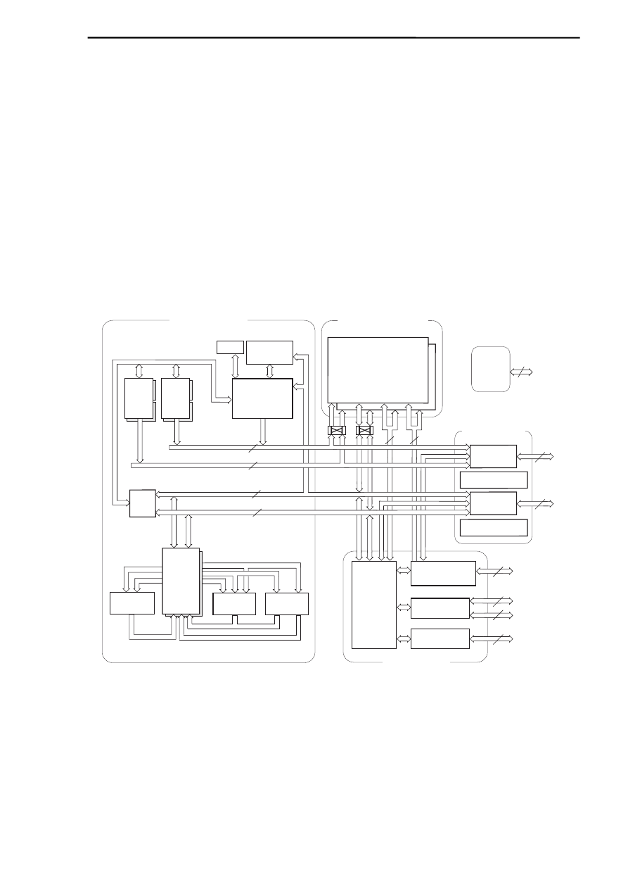
Procesor sygnałowy ADSP-2106x SHARC jest wysoko wydajnym 32-bitowym
procesorem sygnałowym przeznaczonym do zastosowań w dziedzinie
przetwarzania sygnałów akustycznych i wizyjnych. Do rodziny wymienionych
procesorów należą ADSP-21060, ADSP-21061 i ADSP-21062. Różnią się one
między sobą ilością dostępnej w procesorze pamięci oraz konstrukcją procesora
I/O. Rysunek 1 przedstawia blokowy schemat architektury tego procesora.
Rys. 1
AAAAAAA
AAAAAAA
AAAAAAA
AAAAAAA
PM Address Bus (PMA) 24
DM Address Bus (DMA) 32
PM Data Bus (PMD)
DM Data Bus (DMD)
AA
AA
A
A
AAAAAA
AAAAAA
AAAAAA
AAAAAA
AAAAAA
AAAAAA
PROCESSOR PORT
I/O PORT
SERIAL PORTS
(2)
LINK PORTS
(6)
INSTRUCTION
CACHE
32 x 48-Bit
DAG 2
8 x 4 x 24
DAG 1
8 x 4 x 32
TIMER
DMA
CONTROLLER
Addr
Bus
Mux
32
48
AAAA
AAAA
AAAA
AAAA
AAAA
AAAA
IOP
REGISTERS
Control,
Status, &
Data Buffers
6
6
36
4
AAAAAA
AAAAAA
AAAAAA
AAAAAA
AAAAAAA
AAAAAAAAAAAAA
AAAAAAAAAA
A
A
ADDR
DATA
ADDR
DATA
AA
7
A
A
JTAG
Bus
Connect
(PX)
MULTIPLIER
BARREL
SHIFTER
ALU
AAAAAAAA
A
A
A
AA
AA
DATA
REGISTER
FILE
16 x 40-Bit
AAAAAA
Core Processor
AAAAA
AAAAA
Dual-Ported SRAM
Two Independent,
Dual-Ported Blocks
BLOCK 0
BLOCK 1
AAAAA
AAAAA
External Port
HOST INTERFACE
Test &
Emulation
PROGRAM
SEQUENCER
MULTIPROCESSOR
INTERFACE
48
IOD
48
IOA
17
AAAAAAAAA
IOD
EPD
DMD
PMD
EPA
IOA
AAAAA
I/O Processor
AAAAAAA
32/40
PMA
EPA
DMA
PMD
EPD
DMD
Data
Bus
Mux
AAAAAAAAAAAAA
*
* not available on the ADSP-21061

PROCESORY SYGNAŁOWE – Instrukcja laboratoryjna
3
W konstrukcji procesora można wyróżnić kilka zasadniczych bloków:
•
Core Processor - stanowiąca rdzeń systemu jednostka odpowiedzialna za
wykonywanie programu i wszystkie operacje obliczeniowe. Jest ona zgodna
konstrukcyjnie ze starszymi procesorami serii ADSP – 21000.
•
Dual-Ported SRAM – dwuportowa pamięć RAM podzielona na dwa bloki.
•
I/O Processor – procesor wejścia-wyjścia odpowiedzialny za niezależną od
jednostki obliczeniowej wymianę danych z otoczeniem
•
External Port – moduł odpowiedzialny za komunikację procesora z innymi
procesorami w systemach wieloprocesorowych lub za komunikację z
procesorem nadrzędnym (nie musi to być procesor sygnałowy)
•
JTAG – port umożliwiający podłączenie emulatora EZ-ICE.
2.1. Core
Processor
Procesor ten składa się z następujących elementów:
•
trzech jednostek obliczeniowych (computation units)
•
sekwencera programu (program sequencer)
•
dwóch generatorów adresów dla danych (data adress generators DAG)
•
timera
•
pamięci cache dla instrukcji (instruction cache)
•
zbioru rejestrów (data register file)
2.1.1. Jednostki
obliczeniowe
Rdzeń procesora składa się z trzech jednostek obliczeniowych:
•
ALU
•
jednostki
mnożącej (multiplier)
•
jednostki
przesuwającej (shifter)
Jednostki te mogą przetwarzać dane w następujących formatach:
•
32-bitowy
stałoprzecinkowy
•
32-bitowy
zmiennoprzecinkowy
•
40-bitowy
zmiennoprzecinkowy
Jednostki te wykonują obliczenia w jednym cyklu. Dana wyjściowa z jednej
jednostki może stanowić daną wejściową dla drugiej jednostki obliczeniowej.
Możliwe jest również równoległe wykonywanie operacji np. dodawania i
mnożenia dzięki temu, że operacje te wykonywane są przez różne jednostki
obliczeniowe. Wymagany jest wtedy jednak określony wybór rejestrów
przechowujących argumenty dla operacji.
2.1.2.
Zbiór rejestrów (Data Register File)
Zawarte w „rdzeniu” rejestry są rejestrami ogólnego przeznaczenia i
wykorzystywane są do przesyłania danych pomiędzy jednostkami
obliczeniowymi a magistralami danych oraz do przechowywania wyników
pośrednich. Zbiór rejestrów składa się z dwóch zestawów po 16 rejestrów 40-
bitowych każdy. Umożliwia to szybkie przełączanie kontekstów
2.1.3.
Sekwencer programu i generatory adresów

PROCESORY SYGNAŁOWE – Instrukcja laboratoryjna
4
Dwa dedykowane generatory adresów oraz sekwencer programu
wypracowują adresy wykorzystywane w trakcie dostępu do pamięci. Pozwala
to na wykonywanie operacji obliczeniowych z maksymalną efektywnością.
Wykorzystując pamięć cache programu procesor jest w stanie w tym samym
czasie pobrać instrukcję oraz dwa operandy z pamięci. Dokładne informacje
na temat generatorów adresów zamieszczone są w dalszej części instrukcji.
2.1.4. Pamięć cache
Sekwencer programu zawiera 32-słowowy cache instrukcji, który
pozwala w efekcie na trzymagistralową operację pobrania kodu rozkazu oraz
dwóch argumentów.
2.1.5. Przerwania
System przerwań procesora ADSP-2106x oparty jest na czterech
zewnętrznych przerwaniach sprzętowych oraz grupie przerwań
wewnętrznych. Trzy z przerwań sprzętowych są przerwaniami do zastosowań
ogólnych, czwarte jest specjalnym przerwaniem powodującym reset
procesora. Przerwania wewnętrzne pochodzą od timera, sterownika DMA,
przepełnienia buforów cyklicznych, przepełnienia stosu, wyjątków w
obliczeniach arytmetycznych. Generowane są również przerwania
definiowane przez użytkownika oraz związane z pracą wieloprocesorową
2.1.6. Timer
Programowany timer pozwala na cykliczne generowanie przerwania.
Wyposażony jest w 32-bitowy rejestr, który jest dekrementowany w każdym
cyklu. Gdy osiągnie 0, generowane jest przerwanie.
2.1.7. Magistrale
procesora
„Rdzeń” procesora wyposażony jest w cztery magistrale: magistralę
adresową pamięci programu, magistralę adresową pamięci danych,
magistralę danych pamięci programu i magistralę danych pamięci danych.
Pamięć danych przeznaczona jest do przechowywania wartości zmiennych
natomiast pamięć programu przechowuje zarówno program, jak też dane nie
ulegające zmianie w trakcie działania programu np. tablice współczynników.
Dzięki temu w pewnych przypadkach jeżeli kod instrukcji dostarczany jest z
pamięci cache, można w jednym cyklu pobrać kod rozkazu i dwa argumenty.
Wielkości magistral pokazane są na rys. 1.
2.1.8. Wewnętrzne przesyły danych
Prawie każdy rejestr w „rdzeniu” procesora klasyfikowany jest jako
rejestr uniwersalny. Zaimplementowana jest grupa instrukcji pozwalających

PROCESORY SYGNAŁOWE – Instrukcja laboratoryjna
5
na wewnętrzne przesyły pomiędzy rejestrami lub rejestrami i pamięcią
programu lub danych włączając w to rejestry sterujące i rejestry statusu.
Rejestr PX pozwala na wymianę danych pomiędzy magistralą danych
pamięci programu a magistralą danych pamięci danych.
2.1.9. Przełączanie kontekstów
Większość rejestrów procesora posiada swoje alternatywne
odpowiedniki w drugim zestawie co pozwala na szybkie przełączenie
kontekstów przy np. obsłudze przerwań. O tym, który zestaw rejestrów jest
dostępny decyduje ustawienie stosownego bitu w odpowiednim rejestrze
sterującym.
2.1.10. Lista
rozkazów
Lista rozkazów procesorów rodziny ADSP-21000 dostarcza dużą gamę
rozkazów pozwalających na efektywne programowanie. Tzw. instrukcje
wielofunkcyjne pozwalają na równoległe wykonywanie obliczeń i przesyłanie
danych, jak również na jednoczesne wykonywanie mnożenia i operacji na
ALU. Każda instrukcja może być wykonana w jednym cyklu procesora. Język
assemblera wykorzystuje notację algebraiczną co zwiększa czytelność kodu.
2.2. Dwuportowa
pamięć wewnętrzna
Procesor ADSP-21060 wyposażony jest w 4 Mb pamięci RAM
zorganizowanej w dwa bloki po 2Mb każdy. ADSP-21062 posiada 2 Mb pamięci
RAM w dwóch blokach po 1 Mb, a ADSP-21061 1 MB pamięci RAM w dwóch
blokach po 0.5 Mb.
Każdy blok pamięci ma dostęp dwuportowy co pozwala na jednoczesny
dostęp „rdzenia” procesora oraz procesora wejścia/wyjścia lub sterownika DMA.
Cała pamięć może być zorganizowana w słowa o długości 16, 32 lub 48
bitów. W procesorze ADSP-21060 pamięć może być skonfigurowana jako 128K
słów 32-bitowych, 256K słów 16-bitowych lub 80K słów 48-bitowych dla instrukcji
i 40-bitowych dla danych. Dla pozostałych procesorów wartości te są
odpowiednio mniejsze. Każdy z bloków pamięci może przechowywać zarówno
dane jak i program. Jednak zalecana jest taka organizacja, w której jeden blok
przechowuje program, a drugi dane. Wtedy magistrale danych obsługują jeden
blok, a magistrale programu drugi.
2.3. Pamięć zewnętrzna i interfejs urządzeń peryferyjnych
Procesor ADSP-2106x jest wyposażony w interfejs komunikacyjny z pamięcią
zewnętrzną i urządzeniami peryferyjnymi. Zewnętrzna pamięć może być
rozbudowana do 4G słów. Wszystkie wewnętrzne magistrale są multipleksowane
i przetwarzane na 32-bitową zewnętrzną magistralę adresową i 48-bitową
zewnętrzną magistralę danych. Zewnętrzna pamięć może być 16, 32 lub 48-
bitowa.

PROCESORY SYGNAŁOWE – Instrukcja laboratoryjna
6
2.4. Interfejs procesora nadrzędnego
Procesor ADSP-2106x może być w łatwy sposób dołączony do standardowej
magistrali mikroprocesora tak 16 jak i 32-bitowego. Transmisja może być
realizowana z prędkościami do szybkości zegara procesora DSP włącznie. Do
połączenia tego dedykowane są cztery kanały DMA, i procesor nadrzędny może
dzięki temu bezpośrednio odczytywać i zapisywać pamięć DSP.
2.5. Procesor
wejścia/wyjścia
Procesor wejścia/wyjścia zawiera dwa porty szeregowe, sześć 4-bitowych
tzw. link ports i sterownik DMA.
2.5.1. Porty
szeregowe
Dwa synchroniczne porty szeregowe pozwalają na połączenie z szeroką
gamą cyfrowych i cyfrowo-analogowych urządzeń zewnętrznych. Mogą one
działać z maksymalną prędkością odpowiadającą szybkości zegara
procesora czyli transmisja może odbywać się z prędkością do 40Mb/s.
Funkcje nadawcze i odbiorcze każdego portu są niezależne. Dane z portów
szeregowych mogą być transmitowane via DMA do lub z pamięci.
2.5.2. Link
ports
Link ports to specyficznego typu porty równoległe. Porty te są
najczęściej wykorzystywane do komunikacji w systemach
wieloprocesorowych.
Jest ich sześć, każdy o wielkości 4 bity. Mogą być taktowane dwa razy na
cykl procesora co pozwala na przesył 8 bitów na cykl. Link ports mogą
działać niezależnie i równolegle co pozwala na maksymalny transfer
240Mb/s. Dane są pakowane w słowa 32 lub 48-bitowe i mogą być
odczytywane bezpośrednio przez „rdzeń” procesora lub za pośrednictwem
DMA przesyłane do pamięci.
Procesor ADSP-21061 nie jest wyposażony w link ports.
2.5.3. Sterownik
DMA
Procesory ADSP-21060 i ADSP-21062 są wyposażone w dziesięć
kanałów DMA, dwa dla link ports, cztery dla portów szeregowych i cztery dla
interfejsu zewnętrznego. Pozostałe cztery link ports dzielą kanały DMA z
portami szeregowymi i interfejsem zewnętrznym. Procesor ADSP-21061 jako
wersja uproszczona jest wyposażony w sześć kanałów DMA. Sterownik DMA
pracuje niezależnie i niewidocznie dla „rdzenia” procesora, pozwalając (dzięki
dwuportowej konstrukcji pamięci) na jednoczesny dostęp „rdzenia” procesora
i DMA do pamięci. Poprzez DMA do procesora mogą być przesyłane
zarówno dane jak i program.
Możliwe są przesyły DMA pomiędzy pamięcią wewnętrzną i
zewnętrzną lub urządzeniem zewnętrznym lub procesorem nadrzędnym.

PROCESORY SYGNAŁOWE – Instrukcja laboratoryjna
7
Również dane z/do portów szeregowych lub link ports mogą być przesyłane
poprzez DMA. Przy przesyłach zewnętrznych dane są automatycznie
formatowane w słowa 16, 32 lub 48-bitowe.
3. Dane szczegółowe
Trzecia część instrukcji zawiera wybór informacji z danych technicznych procesora
ADSP-2106x, których znajomość jest niezbędna do przeprowadzenia
zaplanowanego ćwiczenia laboratoryjnego. Znajdują się tu informacje dotyczące
sprzętowej strony zagadnienia, jak również wybrane rozkazy assemblera oraz
informacje na temat łączenia procedur assemblerowym z programami w języku C.

PROCESORY SYGNAŁOWE – Instrukcja laboratoryjna
8
3.1. Organizacja generatorów adresów DAG

4
Data Addressing
4 – 1
4.1
OVERVIEW
The ADSP-2106x’s two data address generators (DAGs) simplify the task of
organizing data by maintaining pointers into memory. The DAGs allow the
processor to address memory indirectly; that is, an instruction specifies a
DAG register containing an address instead of the address value itself.
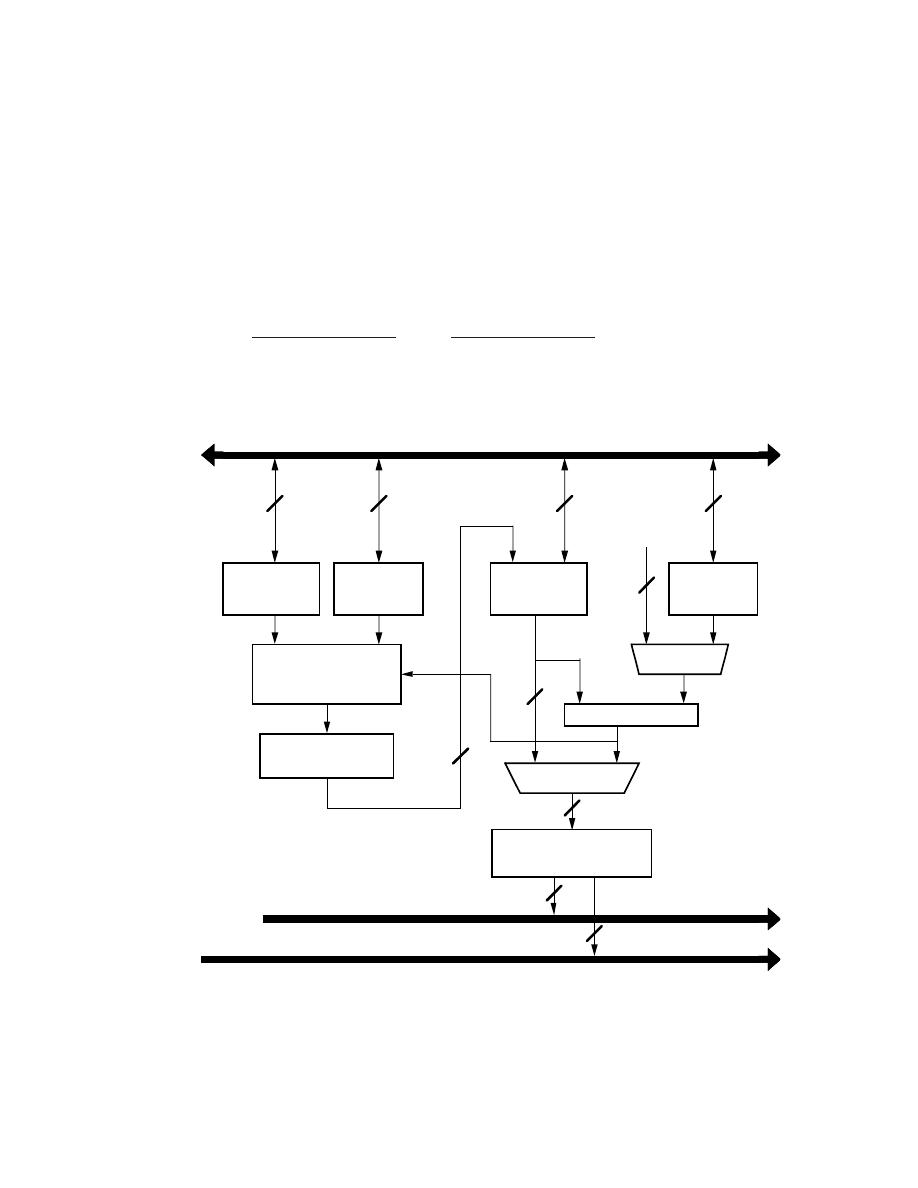
Data address generator 1 (DAG1) generates 32-bit addresses on the
DM Address Bus. Data address generator 2 (DAG2) generates 24-bit
addresses on the PM Address Bus. The basic architecture for both DAGs
is shown in Figure 4.1 on the following page.
The DAGs also support in hardware some functions commonly used in
digital signal processing algorithms. Both DAGs support circular data
buffers, which require advancing a pointer repetitively through a range of
memory. Both DAGs can also perform a bit-reversing operation, which
outputs the bits of an address in reversed order.
4.2
DAG REGISTERS
Each DAG has four types of registers: Index (I), Modify (M), Base (B), and
Length (L) registers.
An I register acts as a pointer to memory, and an M register contains the
increment value for advancing the pointer. By modifying an I register with
different M values, you can vary the increment as needed.
B registers and L registers are used only for circular data buffers. A
B register holds the base address (i.e. the first address) of a circular buffer.
The same-numbered L register contains the number of locations in (i.e. the
length of) the circular buffer.
4 Data Addressing
4 – 2
Each DAG contains eight of each type of register:
DAG1 registers (32-bit)
DAG2 registers (24-bit)
B0-B7
B8-B15
I0-I7
I8-I15
M0-M7
M8-M15
L0-L7
L8-L15
L
Registers
8 x N
DM Data Bus
ADD
I
Registers
8 x N
M
Registers
8 x N
MODULUS
LOGIC
N
N
N
FROM
INSTRUCTION
B
Registers
8 x N
MUX
MUX
N
N
BIT-REVERSE
(Optional)
N
UPDATE
N
N
DAG1: N=32
DAG2: N=24
BIT-REVERSE
I0 (DAG1) or I8 (DAG2) only
(Optional)
24
DM Address Bus (DAG1)
PM Address Bus (DAG2)
32
Figure 4.1 Data Address Generator Block Diagram
4
Data Addressing
4 – 3
4.2.1
Alternate DAG Registers
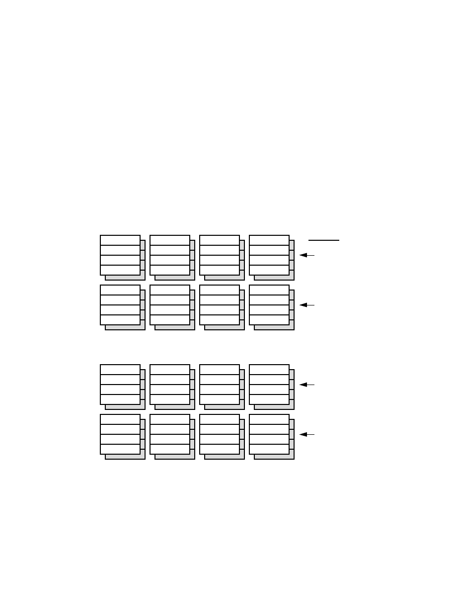
Each DAG register has an alternate (secondary) register for context
switching. For activating alternate registers, each DAG is organized into
high and low halves, as shown in Figure 4.2. The high half of DAG1
contains the I, M, B and L registers numbered 4-7, and the low half, the
registers numbered 0-3. Likewise, the high half of DAG2 consists of
registers 12-15, and the low half consists of registers 8-11.
I0
I1
I2
I3
I4
I5
I6
I7
I8
I9
I10
I11
I12
I13
I15
I14
M0
M1
M2
M3
M4
M5
M6
M7
M8
M9
M10
M11
M12
M13
M15
M14
L0
L1
L2
L3
L4
L5
L6
L7
L8
L9
L10
L11
L12
L13
L15
L14
B0
B1
B2
B3
B4
B5
B6
B7
B8
B9
B10
B11
B12
B13
B15
B14
DAG1 Registers (Data Memory)
DAG2 Registers (Program Memory)
SRD1H
SRD1L
SRD2H
SRD2L
MODE1
Select Bit
Figure 4.2 Alternate DAG Registers

4 Data Addressing
4 – 4
Several control bits in the MODE1 register determine for each half
whether primary or alternate registers are active (0=primary registers,
1=alternate registers):
MODE1
Bit
Name
Definition
3
SRD1H
DAG1 alternate register select (4-7)
4
SRD1L
DAG1 alternate register select (0-3)
5
SRD2H
DAG2 alternate register select (12-15)
6
SRD2L
DAG2 alternate register select (8-11)
This grouping of alternate registers lets you pass pointers between
contexts in each DAG.
4.3
DAG OPERATION
DAG operations include:
• address output with pre-modify or post-modify,
• modulo addressing (for circular buffers), and
• bit-reversed addressing
Short word addresses (for 16-bit data) are right-shifted by one bit before
being output onto the DM Address Bus. This allows internal memory to
use the address directly. (See “16-Bit Short Words” in the Memory chapter
of this manual for details on short word addresses.)
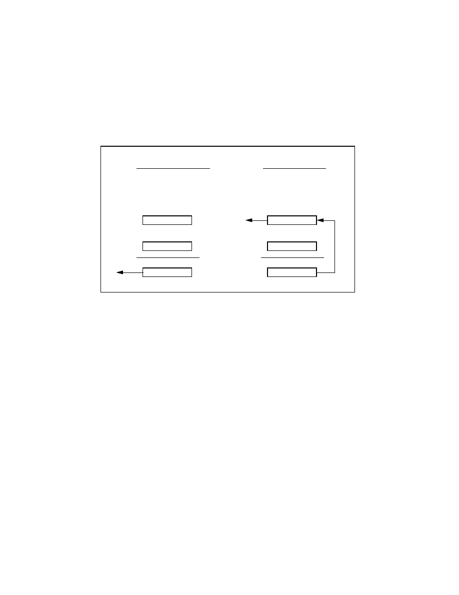
4.3.1
Address Output & Modification
The processor can add an offset (modifier), either an M register or an
immediate value, to an I register and output the resulting address; this is
called a pre-modify without update operation. Or it can output the I register
value as it is, and then add an M register or immediate value to form a
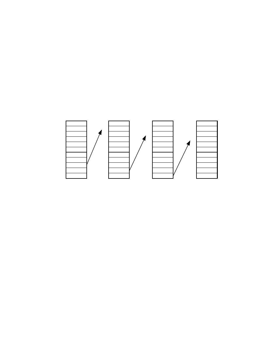
new I register value. This is a post-modify operation. These operations are
compared in Figure 4.3. The pre-modify operation does not change the
value of the I register. The width of an immediate modifier depends on
the instruction; it can be as large as the width of the I register. The L
register and modulo logic do not affect a pre-modified address—
pre-modify addressing is always linear, not circular.
Pre-modify addressing operations must not change the memory space of
the address; for example, pre-modification of an address in ADSP-2106x
Internal Memory Space should not generate an address in External
Memory Space. Refer to the Memory chapter for information on the
ADSP-2106x memory map.
4
Data Addressing
4 – 5
I
M
I
M
+
+
I + M
I + M
1. output
2. update
output
PM (Mx, Ix)
PM (Ix, Mx)
PRE-MODIFY
Without I Register Update
POST-MODIFY
With I Register Update
DM (Ix, Mx)
DM (Mx, Ix)
Figure 4.3 Pre-Modify & Post-Modify Operations
4.3.1.1 DAG Modify Instructions
In ADSP-2106x assembly language, pre-modify and post-modify
operations are distinguished by the positions of the index and modifier
(M register or immediate value) in the instruction. The I register before the
modifier indicates a post-modify operation. If the modifier comes first, a
pre-modify without update operation is indicated. The following
instruction, for example, accesses the program memory location with an
address equal to the value stored in I15, and the value I15 + M12 is written
back to the I15 register:
R6 = PM(I15,M12);
Indirect addressing with post-modify
If the order of the I and M registers is switched, however,
R6 = PM(M12,I15);
Indirect addressing with pre-modify
the instruction accesses the location in program memory with an address
equal to I15 + M12, but does not change the value of I15.

4 Data Addressing
4 – 6
Any M register can modify any I register within the same DAG (DAG1 or
DAG2). Thus,
DM(M0,I2) = TPERIOD;
is a legal instruction that accesses the data memory location M0 + I2;
however,
DM(M0,I14) = TPERIOD;
is not a legal instruction because the I and M registers belong to different
DAGs.
4.3.1.2 Immediate Modifiers
The magnitude of an immediate value that can modify an I register
depends on the instruction type and whether the I register is in DAG1 or
DAG2. DAG1 modify values can be up to 32 bits wide; DAG2 modify
values can be up to 24 bits wide. Some instructions with parallel
operations only allow modify values up to 6 bits wide. Here are two
examples:
32-bit modifier:
R1=DM(0x40000000,I1);
DM address = I1 + 0x4000 0000
6-bit modifier:
F6=F1+F2,PM(I8,0x0B)=ASTAT;
PM address = I8, I8 = I8 + 0x0B
4.3.2
Circular Buffer Addressing
The DAGs provide for addressing of locations within a circular data
buffer. A circular buffer is a set of memory locations that stores data. An
index pointer steps through the buffer, being post-modified and updated
by the addition of a specified value (positive or negative) for each step. If
the modified address pointer falls outside the buffer, the length of the
buffer is subtracted from or added to the value, as required to wrap the
index pointer back to the start of the buffer (see Figure 4.4). There are no
restrictions on the value of the base address for a circular buffer.
Circular buffer addressing must use M registers for post-modify of I
registers, not pre-modify; for example:
F1=DM(I0,M0);
Use post-modify addressing for circular buffers,
F1=DM(M0,I0);
not pre-modify.
4
Data Addressing
4 – 7
0
1
2
3
4
5
6
7
8
9
10
0
1
2
3
4
5
6
7
8
9
10
0
1
2
3
4
5
6
7
8
9
10
0
1
2
3
4
5
6
7
8
9
10
1
2
3
4
5
6
7
8
9
10
11
Length = 11
Base address = 0
Modifier (step size) = 4
Sequence shows order in which locations are accessed in one pass.
Sequence repeats on subsequent passes.
Figure 4.4 Circular Data Buffers
4.3.2.1 Circular Buffer Operation
You set up a circular buffer in assembly language by initializing an
L register with a positive, nonzero value and loading the corresponding
(same-numbered) B register with the base (starting) address of the buffer.
The corresponding I register is automatically loaded with this same
starting address.
On the first post-modify access using the I register, the DAG outputs the I
register value on the address bus and then modifies it by adding the
specified M register or immediate value to it. If the modified value is
within the buffer range, it is written back to the I register. If the value is
outside the buffer range, the L register value is subtracted (or, if the
modify value is negative, added) first.

4 Data Addressing
4 – 8
If M is positive,
I
new
= I
old
+ M
if I
old
+ M < Buffer base + length (end of buffer)
I
new
= I
old
+ M – L
if I
old
+ M
≥
Buffer base + length (end of buffer)
If M is negative,
I
new
= I
old
+ M
if I
old
+ M
≥
Buffer base (start of buffer)
I
new
= I
old
+ M + L
if I
old
+ M < Buffer base (start of buffer)
4.3.2.2 Circular Buffer Registers
All four types of DAG registers are involved in the operation of a circular
buffer:
• The I register contains the value which is output on the address bus.
• The M register contains the post-modify amount (positive or negative)
which is added to the I register at the end of each memory access. The
M register can be any M register in the same DAG as the I register and
does not have to have the same number. The modify value can also be an
immediate number instead of an M register. The magnitude of the
modify value, whether from an M register or immediate, must be less
than the length (L register) of the circular buffer.
• The L register sets the size of the circular buffer and thus the address
range that the I register is allowed to circulate through. L must be
positive and cannot have a value greater than 2
31
– 1 (for L0-L7) or
2
23
– 1 (for L8-L15). If an L register’s value is zero, its circular buffer
operation is disabled.
• The B register, or the B register plus the L register, is the value that the
modified I value is compared to after each access. When the B register is
loaded, the corresponding I register is simultaneously loaded with the
same value. When I is loaded, B is not changed. B and I can be read
independently.
4.3.2.3 Circular Buffer Overflow Interrupts
There is one set of registers in each DAG that can generate an interrupt upon
circular buffer overflow (i.e. address wraparound). In DAG1, the registers
are B7, I7, L7, and in DAG2 they are B15, I15, L15. Circular buffer overflow
interrupts can be used to implement a ping-pong (i.e. swap I/O buffer
pointers) routine, for example.

4
Data Addressing
4 – 9
Whenever a circular buffer addressing operation using these registers
causes the address in the I register to be incremented (or decremented)
past the end (or start) of the circular buffer, an interrupt is generated.
Depending on which register set was used, the interrupt is either:
DAG Registers
Vector
Symbolic
Interrupt
To Use
Address
Name*
DAG1 circular buffer 7 overflow
B7, I7, L7
0x54
CB7I
DAG2 circular buffer 15 overflow
B15, I15, L15
0x58
CB15I
* These symbols are defined in the #include file
def21060.h
. See “Symbol
Definitions File (def21060.h)” at the end of Appendix E, Control/Status Registers.
Specifically, an interrupt is generated during an instruction’s address
post-modify when:
(for M<0)
I + M < B
(for M
≥
0)
I + M
≥
B + L
The interrupts can be masked by clearing the appropriate bit in IMASK.
There may be situations where you want to use I7 or I15 without circular
buffering but with the circular buffer overflow interrupts unmasked. To
disable the generation of these interrupts, set the B7/B15 and L7/L15
registers to values that assure the conditions that generate interrupts (as
specified above) never occur. For example, when accessing the address
range 0x1000–0x2000, your program could set B=0x0000 and L=0xFFFF.
Note that setting the L register to zero will not achieve the desired results.
If you are using either of the circular buffer overflow interrupts, you
should avoid using the corresponding I register(s) (I7, I15) in the rest of
your program, or be careful to set the B and L registers as described above
to prevent spurious interrupt branching.
The STKY status register includes two bits that also indicate the
occurrence of a circular buffer overflow, bit 17 (DAG1 circular buffer 7
overflow) and bit 18 (DAG2 circular buffer 15 overflow). These bits are
“sticky”—they remain set until explicitly cleared.

PROCESORY SYGNAŁOWE – Instrukcja laboratoryjna
18
3.2. Plik
konfiguracyjny
pamięci
Jak już wcześniej wspomniano pamięc omawianych procesorów podzielona
jest na dwa bloki i zasadniczo zgodnie z zaleceniami jeden blok powinien
stanowić pamięć programu, a drugi pamięć danych. Aby jednak w sposób
logiczny zorganizować pamięć stosuje się opis struktury pamięci przy pomocy
plików .ach. Poniżej przedstawiono plik ez-kit.ach, który opisuje podział pamięci
dla systemu uruchomieniowego EZ-KIT i pozwala na uruchamianie programów
napisanych w języku C. Nazwy segmentów są w tym przypadku jednoznacznie
określone i należy się do nich odwoływać w czasie pisania procedur
assemblerowych łączonych z programami w C.
EZ-KIT Architecture File
!---------------------------------------------------------------------
.SYSTEM SHARC_EZKIT_Lite;
!
! This architecture file is required for used with the SHARC EZ-KIT
! Lite development software. It is structured for use with the C
! compiler but also can be used with assembly code.
!
! This architecture file allocates:
! Internal 133 words of 48-bit run-time header in memory block 0
! 16 words of 48-bit initialization code in memory block 0
! 619 words of 48-bit kernel code in memory block 0
! 7424 words of 48-bit C code space in memory block 0
! 4K words of 32-bit PM C data space in memory block 0
!
! 8K words of 32-bit C DM data space in memory block 1
! 4K words of 32-bit C heap space in memory block 1
! 3712 words of 32-bit C stack space in memory block 1
! 384 words of 32-bit kernel data in memory block 1
.PROCESSOR = ADSP21061;
! -------------------------------------------------------------
! Internal memory Block 0
! -------------------------------------------------------------
.SEGMENT/RAM/BEGIN=0x00020000 /END=0x00020084 /PM/WIDTH=48 seg_rth;
.SEGMENT/RAM/BEGIN=0x00020085 /END=0x00020094 /PM/WIDTH=48 seg_init;
.SEGMENT/RAM/BEGIN=0x00020095 /END=0x000202ff /PM/WIDTH=48 seg_knlc;
.SEGMENT/RAM/BEGIN=0x00020300 /END=0x00021fff /PM/WIDTH=48 seg_pmco;
.SEGMENT/RAM/BEGIN=0x00023000 /END=0x00023fff /PM/WIDTH=32 seg_pmda;
! -------------------------------------------------------------
! Internal memory Block 1
! -------------------------------------------------------------
.SEGMENT/RAM/BEGIN=0x00024000 /END=0x00025fff /DM/WIDTH=32 seg_dmda;
.SEGMENT/RAM/BEGIN=0x00026000 /END=0x00026fff /DM/WIDTH=32 /cheap seg_heap;
.SEGMENT/RAM/BEGIN=0x00027000 /END=0x00027e7f /DM/WIDTH=32 seg_stak;
.SEGMENT/RAM/BEGIN=0x00027e80 /END=0x00027fff /DM/WIDTH=32 seg_knld;
! -------------------------------------------------------------
! External Memory Select 1 is reserved for the UART.
! -------------------------------------------------------------
.ENDSYS;

PROCESORY SYGNAŁOWE – Instrukcja laboratoryjna
19
3.3. Lista rozkazów – przegląd
Przedstawiona dalej lista rozkazów stanowi skrócony przegląd pełnej listy
rozkazów. W celu zdobycia pełnej informacji nt. poszczególnych rozkazów
należy skorzystać z dokumentacji w formie plików .pdf dostępnych na serwerze
JOY w katalogu P:\DSP\DOC
oraz na wskazanej przez prowadzacego stronie WWW.

A
Instruction Set Reference
A – 1
A.1
OVERVIEW
This appendix and the next one describe the ADSP-2106x instruction set in
detail. This appendix explains each instruction type, including the
assembly language syntax and the opcode that the instruction assembles
to. Many instruction types contain a field for specifying a compute
operation (an operation that uses the ALU, multiplier or shifter). Because
there are a large number of options available for this field, they are
described separately in Appendix B. (Note that data moves between the
MR registers and the register file are considered multiplier operations.)
Each instruction is specified in this section. The specification shows the
syntax
of the instruction, describes its function, gives one or two
assembly-language examples, and specifies and describes the various
fields of its opcode. The instructions are grouped into four categories:
I. Compute and Move or Modify instructions, which specify a compute
operation in parallel with one or two data moves or an index register
modify.
II. Program Flow Control instructions, which specify various types of
branches, calls, returns and loops. Some of these instructions may also
specify a compute operation and/or a data move.
III. Immediate Data Move instructions, which use immediate instruction
fields as operands, or use immediate instruction fields for addressing.
IV. Miscellaneous instructions, such as bit modify and test, no operation
and idle.
The instructions are numbered from 1 to 23. Some instructions have more
than one syntactical form; for example, Instruction Type 4 has four distinct
forms. The instruction number has no bearing on programming, but
corresponds to the opcode recognized by the ADSP-2106x device.
Many instructions can be conditional. These instructions are prefaced by
an “IF” plus a condition mnemonic. In a conditional instruction, the
execution of the entire instruction is based on the specified condition.

Instruction Set Reference
A
A – 2
A.2
INSTRUCTION SET SUMMARY
The next few pages summarize the ADSP-2106x instruction set. The
compute operations used within each instruction are specified in
Appendix B.
(pg. A-16)
(pg. A-17)
(pg. A-18)
(pg. A-20)
(pg. A-22)
(pg. A-24)
(pg. A-26)
Compute & Move or Modify Instructions
1.
compute,
DM(Ia,Mb) = dreg1 , PM(Ic,Md) = dreg2 ;
dreg1 = DM(Ia,Mb)
dreg2 = PM(Ic,Md)
2.
IF condition
compute;
3a.
IF condition
compute,
DM(Ia,Mb) = ureg ;
PM(Ic,Md)
3b.
IF condition
compute,
DM(Mb,Ia) = ureg ;
PM(Md,Ic)
3c.
IF condition
compute,
ureg = DM(Ia,Mb) ;
PM(Ic,Md)
3d.
IF condition
compute,
ureg = DM(Mb,Ia) ;
PM(Md,Ic)
4a.
IF condition
compute,
DM(Ia,<data6>) = dreg ;
PM(Ic,<data6>)
4b.
IF condition
compute,
DM(<data6>,Ia) = dreg ;
PM(<data6>,Ic)
4c.
IF condition
compute,
dreg = DM(Ia,<data6>) ;
PM(Ic,<data6>)
4d.
IF condition
compute,
dreg = DM(<data6>,Ia) ;
PM(<data6>,Ic)
5.
IF condition
compute,
ureg1 = ureg2 ;
6a.
IF condition
shiftimm,
DM(Ia,Mb) = dreg ;
PM(Ic,Md)
6b.
IF condition
shiftimm,
dreg = DM(Ia,Mb) ;
PM(Ic,Md)
7.
IF condition
compute,
MODIFY (Ia,Mb) ;
(Ic,Md)
➠
Items in italics are an optional part of the instruction.

A
Instruction Set Reference
A – 3
Program Flow Control Instructions
8.
IF condition
JUMP <addr24>
(DB) ;
(PC, <reladdr24>)
(LA)
(CI)
(DB,LA)
(DB,CI)
IF condition
CALL <addr24>
(DB) ;
(PC, <reladdr24>)
9.
IF condition
JUMP (Md,Ic)
(DB) ,
compute ;
(PC, <reladdr6>)
(LA)
ELSE compute
(CI)
(DB,LA)
(DB,CI)
IF condition
CALL (Md,Ic)
(DB) ,
compute ;
(PC, <reladdr6>)
ELSE compute
10.
IF condition JUMP (Md,Ic) , ELSE compute , DM(Ia,Mb) = dreg ;
(PC, <reladdr6>)
compute , dreg = DM(Ia,Mb)
11.
IF condition
RTS (DB) , compute
;
(LR)
ELSE compute
(DB,LR)
IF condition
RTI
(DB) ,
compute
;
ELSE compute
12.
LCNTR = <data16> ,
DO <addr24>
UNTIL LCE ;
ureg
(PC, <reladdr24>)
13.
DO <addr24>
UNTIL termination ;
(PC, <reladdr24>)
(pg. A-28)
(pg. A-30)
(pg. A-32)
(pg. A-34)
(pg. A-36)
(pg. A-38)
➠
Items in italics are an optional part of the instruction.

Instruction Set Reference
A
A – 4
(pg. A-46)
(pg. A-48)
(pg. A-50)
(pg. A-51)
(pg. A-52)
(pg. A-53)
(pg. A-54)
Immediate Move Instructions
14a.
DM(<addr32>) = ureg ;
PM(<addr24>)
14b.
ureg = DM(<addr32>) ;
PM(<addr24>)
15a.
DM(<data32>, Ia) = ureg ;
PM(<data24>, Ic)
15b.
ureg = DM(<data32>, Ia) ;
PM(<data24>, Ic)
16.
DM(Ia,Mb) = <data32> ;
PM(Ic,Md)
17.
ureg = <data32> ;
(pg. A-40)
(pg. A-41)
(pg. A-42)
(pg. A-43)
Miscellaneous Instructions
18.
BIT SET
sreg <data32> ;
CLR
TGL
TST
XOR
19a.
MODIFY (Ia, <data32>) ;
(Ic, <data24>)
19b.
BITREV
(Ia, <data32>) ;
(Ic, <data24>)
20.
PUSH LOOP ,
PUSH STS ,
PUSH PCSTK ,
FLUSH CACHE ;
POP
POP
POP
21.
NOP;
22.
IDLE ;
23.
IDLE16 ;
24.
CJUMP
function (DB) ;
(PC, <reladdr24>)
RFRAME ;
Items in italics are an optional part of the instruction.
➠

A
Instruction Set Reference
A – 5
Instruction Set Notation
Notation
Meaning
UPPERCASE
Explicit syntax—assembler keyword (notation only; assembler is case-insensitive
and lowercase is the preferred programming convention)
;
Semicolon (instruction terminator)
,
Comma (separates parallel operations in an instruction)
italics
Optional part of instruction
option1
List of options between vertical bars (choose one)
option2
compute
ALU, multiplier, shifter or multifunction operation (see Appendix B)
shiftimm
Shifter immediate operation (see Appendix B)
condition
Status condition (see condition codes below)
termination
Loop termination condition (see condition codes below)
ureg
Universal register
sreg
System register
dreg
Data register (register file): R15-R0 or F15-F0
Ia
I7-I0 (DAG1 index register)
Mb
M7-M0 (DAG1 modify register)
Ic
I15-I8 (DAG2 index register)
Md
M15-M8 (DAG2 modify register)
<datan>
n-bit immediate data value
<addrn>
n-bit immediate address value
<reladdrn>
n-bit immediate PC-relative address value
(DB)
Delayed branch
(LA)
Loop abort (pop loop and PC stacks on branch)
(CI)
Clear interrupt
Condition & Termination Codes (IF & DO UNTIL)
In a conditional instruction, execution of the entire instruction depends on the specified condition.
Condition
Description
EQ
ALU equal zero
LT
ALU less than zero
LE
ALU less than or equal zero
AC
ALU carry
AV
ALU overflow
MV
Multiplier overflow
MS
Multiplier sign
SV
Shifter overflow
SZ
Shifter zero
FLAG0_IN
Flag 0 input
FLAG1_IN
Flag 1 input
FLAG2_IN
Flag 2 input
FLAG3_IN
Flag 3 input
TF
Bit test flag
BM
Bus master
LCE
Loop counter expired (DO UNTIL)
NOT LCE
Loop counter not expired (IF)
Condition
Description
NE
ALU not equal to zero
GE
ALU greater than or equal zero
GT
ALU greater than zero
NOT AC
Not ALU carry
NOT AV
Not ALU overflow
NOT MV
Not multiplier overflow
NOT MS
Not multiplier sign
NOT SV
Not shifter overflow
NOT SZ
Not shifter zero
NOT FLAG0_IN
Not Flag 0 input
NOT FLAG1_IN
Not Flag 1 input
NOT FLAG2_IN
Not Flag 2 input
NOT FLAG3_IN
Not Flag 3 input
NOT TF
Not bit test flag
NBM
Not bus master
FOREVER
Always false (DO UNTIL)
TRUE
Always true (IF)

Instruction Set Reference
A
A – 6
Universal Registers
Register
Function
Data Register File
R15 - R0
Register file locations, fixed-point
F15 - F0
Register file locations, floating-point
Program Sequencer
PC
Program counter (read-only)
PCSTK
Top of PC stack
PCSTKP
PC stack pointer
FADDR
Fetch address (read-only)
DADDR
Decode address (read-only)
LADDR
Loop termination address, code; top of loop address stack
CURLCNTR Current loop counter; top of loop count stack
LCNTR
Loop count for next nested counter-controlled loop
Data Address Generators
I7 - I0
DAG1 index registers
M7 - M0
DAG1 modify registers
L7 - L0
DAG1 length registers
B7 - B0
DAG1 base registers
I15 - I8
DAG2 index registers
M15 - M8
DAG2 modify registers
L15 - L8
DAG2 length registers
B15 - B8
DAG2 base registers
Bus Exchange
PX1
PMD-DMD bus exchange 1 (16 bits)
PX2
PMD-DMD bus exchange 2 (32 bits)
PX
48-bit combination of PX1 and PX2
Timer
TPERIOD
Timer period
TCOUNT
Timer counter
System Registers
MODE1
Mode control & status
MODE2
Mode control & status
IRPTL
Interrupt latch
IMASK
Interrupt mask
IMASKP
Interrupt mask pointer (for nesting)
ASTAT
Arithmetic status flags, bit test flag, etc.
STKY
Sticky arithmetic status flags, stack status flags, etc.
USTAT1
User status register 1
USTAT2
User status register 2

A
Instruction Set Reference
A – 7
Memory Addressing in Instructions
Direct:
Absolute
Instruction Types 8, 12, 13, 14
Examples:
dm(0x000015F0) = astat;
if ne jump label2; {'label2' is an address label}
PC-relative
Instruction Types 8, 9, 10, 12, 13
Examples:
call(pc,10), r0=r6+r3;
do(pc,length) until sz; {'length' is a variable}
Register Indirect (using DAG registers):
Post-modify with M register, update I register
Instruction Types 1, 3, 6, 16
Examples:
f5=pm(i9,m12);
dm(i0,m3)=r3, r1=pm(i15,m10);
Pre-modify with M register, no update
Instruction Types 3, 9, 10
Examples:
r1=pm(m10,i15);
jump(m13,i11);
Post-modify with immediate value, update I register
Instruction Type 4
Examples:
f15=dm(i0,6);
if av r1=pm(i15,0x11);
Pre-modify with immediate value, no update
Instruction Types 4, 15
Examples:
if av r1=pm(0x11,i15);
dm(127,i5)=laddr;

B
Compute Operation
Reference
B.1
OVERVIEW
Compute operations execute in the multiplier, the ALU and the shifter.
The 23-bit compute field is like a mini-instruction within the ADSP-21000
instruction and can be specified for a variety of compute operations. This
appendix describes each compute operation in detail, including its
assembly language syntax and opcode field.
A compute operation is one of the following:
• Single-function operations involve a single computation unit.
• Multifunction operations specify parallel operation of the multiplier and
the ALU or two operations in the ALU.
• The MR register transfer is a special type of compute operation used to
access the fixed-point accumulator in the multiplier. (See p. B-52).
The operations in each category are described in the following sections.
For each operation, the assembly language syntax, the function, and the
opcode format and contents are specified. Refer to the beginning of
Appendix A for an explanation of the notation and abbreviations used.
B.2
SINGLE-FUNCTION OPERATIONS
The compute field of a single-function operation looks like:
22 21 20 19 18 17 16 15 14 13 12 11 10 9 8 7 6 5 4 3 2 1 0
0
CU
OPCODE
RN
RX
RY
An operation determined by OPCODE is executed in the computation unit
specified by CU. The x- and the y-operands are received from data
registers RX and RY. The result operand is returned to data register RN.
B – 1

B Compute Operations
B – 2
The CU (computation unit) field is defined as follows:
CU=00
ALU operations
CU=01
Multiplier operations
CU=10
Shifter operations
In some shifter operations, data register RN is used both as a destination
for a result operand and as source for a third input operand.
The available operations and their 8-bit OPCODE values are listed in the
following sections, organized by computation unit: ALU, multiplier and
shifter. In each section, the syntax and opcodes for the operations are first
summarized and then the operations are described in detail.
B.2.1
ALU Operations
The ALU operations are described in this section. Tables B.1 and B.2
summarize the syntax and opcodes for the fixed-point and floating-point
ALU operations, respectively. The rest of this section contains detailed
descriptions of each operation.
Syntax
Opcode
Rn = Rx + Ry
0000 0001
Rn = Rx – Ry
0000 0010
Rn = Rx + Ry + CI
0000 0101
Rn = Rx – Ry + CI – 1
0000 0110
Rn = (Rx + Ry)/2
0000 1001
COMP(Rx, Ry)
0000 1010
Rn = Rx + CI
0010 0101
Rn = Rx + CI – 1
0010 0110
Rn = Rx + 1
0010 1001
Rn = Rx – 1
0010 1010
Rn = –Rx
0010 0010
Rn = ABS Rx
0011 0000
Rn = PASS Rx
0010 0001
Rn = Rx AND Ry
0100 0000
Rn = Rx OR Ry
0100 0001
Rn = Rx XOR Ry
0100 0010
Rn = NOT Rx
0100 0011
Rn = MIN(Rx, Ry)
0110 0001
Rn = MAX(Rx, Ry)
0110 0010
Rn = CLIP Rx BY Ry
0110 0011
Table B.1 Fixed-Point ALU Operations

B
Compute Operations
B – 3
Syntax
Opcode
Fn = Fx + Fy
1000 0001
Fn = Fx – Fy
1000 0010
Fn = ABS (Fx + Fy)
1001 0001
Fn = ABS (Fx – Fy)
1001 0010
Fn = (Fx + Fy)/2
1000 1001
COMP(Fx, Fy)
1000 1010
Fn = –Fx
1010 0010
Fn = ABS Fx
1011 0000
Fn = PASS Fx
1010 0001
Fn = RND Fx
1010 0101
Fn = SCALB Fx BY Ry
1011 1101
Rn = MANT Fx
1010 1101
Rn = LOGB Fx
1100 0001
Rn = FIX Fx BY Ry
1101 1001
Rn = FIX Fx
1100 1001
Rn = TRUNC Fx BY Ry
1101 1101
Rn = TRUNC Fx
1100 1101
Fn = FLOAT Rx BY Ry
1101 1010
Fn = FLOAT Rx
1100 1010
Fn = RECIPS Fx
1100 0100
Fn = RSQRTS Fx
1100 0101
Fn = Fx COPYSIGN Fy
1110 0000
Fn = MIN(Fx, Fy)
1110 0001
Fn = MAX(Fx, Fy)
1110 0010
Fn = CLIP Fx BY Fy
1110 0011
Table B.2 Floating-Point ALU Operations
The individual registers of the register file are prefixed with an “F”
when used in floating-point computations. The registers are prefixed
with an “R” when used in fixed-point computations. The following
instructions, for example, use the same registers:
F0=F1
*
F2;
floating-point multiply
R0=R1
*
R2;
fixed-point multiply
The F and R prefixes do not affect the 32-bit (or 40-bit) data transfer;
they only determine how the ALU, multiplier, or shifter treat the data.
The F and R may be either uppercase or lowercase; the assembler is
case-insensitive.

PROCESORY SYGNAŁOWE – Instrukcja laboratoryjna
30
3.4. Łączenie procedur assemblerowych z
programami w języku C

44444
4 – 1
4 – 1
4 – 1
4 – 1
4 – 1
Assembly Language Interface
Assembly Language Interface
Assembly Language Interface
Assembly Language Interface
Assembly Language Interface
4.1
4.1
4.1
4.1
4.1
INTRODUCTION
INTRODUCTION
INTRODUCTION
INTRODUCTION
INTRODUCTION
This chapter describes how to interface assembly language code with C
code.
You must be familiar with ADSP-21000 family assembly language and the C
runtime model to make best use of this chapter. See the ADSP-2106x SHARC
User’s Manual, ADSP-21020 User’s Manual, and the previous chapter of this
manual.
There are several ways to incorporate assembly language statements into a
program that contains code written in C:
• Write assembly language functions that are C-callable
• Use assembly language statements within a C function (by using the
asm()
in-line assembly construct)
• Associate C variables with assembly-language symbols
Throughout this chapter there are references to
asm_sprt.h
, a header file
containing macros to help you write assembly language implementations of
C functions. These macros are summarized at the end of this chapter. This
header file is found in
$ADI_DSP\21K\INCLUDE.
If you use these macros,
any file including the
asm_sprt.h
header file must be processed by the
G21K compiler, and not by the ASM21K assembler only.

44444 Assembly Language Interface
Assembly Language Interface
Assembly Language Interface
Assembly Language Interface
Assembly Language Interface
4 – 2
4 – 2
4 – 2
4 – 2
4 – 2
4.2
4.2
4.2
4.2
4.2
ASSEMBLY LANGUAGE FUNCTIONS
ASSEMBLY LANGUAGE FUNCTIONS
ASSEMBLY LANGUAGE FUNCTIONS
ASSEMBLY LANGUAGE FUNCTIONS
ASSEMBLY LANGUAGE FUNCTIONS
Assembly language functions may be linked with C functions. They
are normally placed in files with the
.s
or
.asm
suffix. There are
several issues involved in writing a C-callable assembly language
function:
Using registers
Retrieving parameters
Calling other functions
Function entry
Function exit
Naming conventions for assembly-language symbols
4.2.1
4.2.1
4.2.1
4.2.1
4.2.1
Using Registers
Using Registers
Using Registers
Using Registers
Using Registers
There are some points to consider when using ADSP-21xxx registers in
assembly language programming under the C runtime environment:
• Most registers of the processor are available to the assembly language
programmer.
• Some registers have special purposes and must be used only for those
purposes. For example, some registers need to contain fixed values for
the compiler.
• If registers are used in assembly language, rules must be followed
when the contents of registers are saved and restored.
• We recommend using the macros in
asm_sprt.h
for saving
registers to the stack and restoring them from it.
4.2.1.1
4.2.1.1
4.2.1.1
4.2.1.1
4.2.1.1 Special Purpose Registers
Special Purpose Registers
Special Purpose Registers
Special Purpose Registers
Special Purpose Registers
Two registers, called the stack pointer and frame pointer, are used to
manipulate the C runtime stack. The C runtime stack is used to store
automatic variables, pass parameters, store function return address,
and store the intermediate results of computations.
The stack pointer, register I7, points to the top of the stack. The top of
the stack is the next empty location on the stack. The stack grows
towards address 0. Thus, if a value is “pushed” on the stack, it is
placed at the location pointed to by the stack pointer and the stack
pointer is decremented.
The frame pointer, register I6, points to the start of the frame for the
current function.

44444
Assembly Language Interface
Assembly Language Interface
Assembly Language Interface
Assembly Language Interface
Assembly Language Interface
4 – 3
4 – 3
4 – 3
4 – 3
4 – 3
4.2.1.2
4.2.1.2
4.2.1.2
4.2.1.2
4.2.1.2 Fixed Value Registers
Fixed Value Registers
Fixed Value Registers
Fixed Value Registers
Fixed Value Registers
M Registers
Several M registers are used to hold fixed values. The run-time header,
which executes on processor startup, sets these registers to their
designated values and calls
main()
. The compiler assumes that these
registers contain their designated values. Assembly language functions
must not change these registers, but may rely on their containing the
following values:
DAG1 Register
DAG2 Register
Value
M5
M13
0
M6
M14
1
M7
M15
-1
L Registers
The compiler requires that the L registers contain zeros. All the L
registers, except for L6 and L7, may be set by an assembly language
function to any value. However,they must be reset to 0 before the
assembly language function returns.
4.2.1.3
4.2.1.3
4.2.1.3
4.2.1.3
4.2.1.3 Saving & Restoring Registers
Saving & Restoring Registers
Saving & Restoring Registers
Saving & Restoring Registers
Saving & Restoring Registers
The compiler makes assumptions about how functions treat registers.
If the compiler knows that a function does not destroy the contents of a
register, the compiler may keep “live” data in that register when the
function call is made. However, if the compiler expects that a
subroutine destroys the contents of a register, the compiler attempts to
avoid keeping useful information in that register when a function call
is made. If the register contains “live” data, then the compiler must
save a copy of that data before the function call and restore that copy
to the register after the function call.
There are two classes of registers:
• Compiler registers are registers that the compiler assumes are
preserved across function calls.
• Scratch registers are registers that the compiler assumes are not
preserved across function calls.
Note:
It is not necessary that the called function actually overwrite
scratch registers; to be safe, the compiler assumes that they are
overwritten.

44444 Assembly Language Interface
Assembly Language Interface
Assembly Language Interface
Assembly Language Interface
Assembly Language Interface
4 – 4
4 – 4
4 – 4
4 – 4
4 – 4
Compiler Registers
Scratch
Registers
Data Registers
R3, R5, R6, R7, R9, R10,
R0, R1, R2, R4,
R11, R13, R14, R15
R8, R12
Index Registers
I0, I1, I2, I3, I5, I8, I9, I10,
I4, I12
I11, I14, I15
Modify Registers
M0, M1, M2, M3, M8,
M4, M12
M9, M10, M11
Other Registers
MRF, MRB, MODE1,
MODE2, USTAT1,
USTAT2
Here are some rules about saving and restoring registers:
1. Registers may be saved by pushing them onto the stack. This is done
as follows:
dm(i7,m7)=r3;
This instruction places register
R3
onto the stack and decrements the
stack pointer.
Note:
Register M7 is fixed at -1.
2. A value may be popped off the stack by reading it, and then adjusting
the stack pointer. The following instructions might be used:
r3=dm(1,i7);
modify(i7,1);
3. The stack pointer must always point to the next empty location on the
stack.
Note:
The one exception to this rule is during the delay branch slots of
the jump at the end of a function. The hardware of the ADSP-210xx
locks out interrupts during these cycles, so you don’t need to worry
about the stack being corrupted.

44444
Assembly Language Interface
Assembly Language Interface
Assembly Language Interface
Assembly Language Interface
Assembly Language Interface
4 – 5
4 – 5
4 – 5
4 – 5
4 – 5
As a negative example, the following code is not recommended
because an interrupt could corrupt the stack.
modify(i7,1); /* NOT recommended */
r3=dm(0,i7);
/* NOT recommended */
If an interrupt occurred after the modify but before the read the stack
would be pointing at valid data. The interrupt service routine would
write over this data.
4. At the beginning of an assembly language function, all compiler
registers that are used in the function must be saved. At the end of an
assembly language function, all those that were saved must be
restored.
5. Before a function call, all scratch registers that contain “live” data must
be saved. After a function call, all those scratch registers that were
saved must be restored.
4.2.1.4
4.2.1.4
4.2.1.4
4.2.1.4
4.2.1.4 Macros For Stack Access
Macros For Stack Access
Macros For Stack Access
Macros For Stack Access
Macros For Stack Access
The header file
asm_sprt.h
includes many macros useful for
interfacing C to assembly language. For example, the
puts()
macro
does a push:
puts=r7;
This instruction pushes
r7
onto the stack. Similarly the
gets()
macro reads off the stack. For example, to read the most recently
pushed value into register
r9
, use this code:
r9=gets(1);
You can use the
restore_reg
macro in conjunction with the
save_reg
macro to save and restore all register file registers (R0-
R15). The macros are found in
asm_sprt.h
. Use them as a templates
for constructing code for performing register saves and restores.

44444 Assembly Language Interface
Assembly Language Interface
Assembly Language Interface
Assembly Language Interface
Assembly Language Interface
4 – 6
4 – 6
4 – 6
4 – 6
4 – 6
4.2.1.5
4.2.1.5
4.2.1.5
4.2.1.5
4.2.1.5 Secondary Register Set
Secondary Register Set
Secondary Register Set
Secondary Register Set
Secondary Register Set
The register file of ADSP-21000 family processors has a complete
secondary set of the primary registers. The C runtime environment
model does not use any of the secondary registers. Therefore, you may
use the secondary register set in assembly language freely. The C
runtime environment is not corrupted by using the secondary register
set. When you switch back to using the primary register set, the
primary registers are as you left them.
4.2.2
4.2.2
4.2.2
4.2.2
4.2.2
Retrieving Parameters
Retrieving Parameters
Retrieving Parameters
Retrieving Parameters
Retrieving Parameters
This section describes how parameters to C functions are accessed.
4.2.2.1
4.2.2.1
4.2.2.1
4.2.2.1
4.2.2.1 Where The Parameters Are
Where The Parameters Are
Where The Parameters Are
Where The Parameters Are
Where The Parameters Are
In the C environment, arguments are passed to functions by placing
them in registers or on the stack, according to the following rules:
1. Up to three arguments may be passed in registers.
The first argument to be passed in a register is placed in
R4
.
The second argument to be passed in a register is placed in
R8
.
The third argument to be passed in a register is placed in
R12
.
2. Once one argument has been passed on the stack, all remaining
arguments (those to the right) are on the stack.
3. All values wider than 32 bits are passed on the stack. These include
variables of type
double
and
complex
, and structures passed by
value.
Whenever a
double
or
float
is placed on the stack, the most
significant word falls at the lower address, the least significant word
at the higher address.
Whenever a
complex
is placed on the stack, the real part is put at
the lower address, the imaginary part is put at the higher address.
4. The last named argument in a function call with a variable number of
arguments is passed on the stack.

44444
Assembly Language Interface
Assembly Language Interface
Assembly Language Interface
Assembly Language Interface
Assembly Language Interface
4 – 7
4 – 7
4 – 7
4 – 7
4 – 7
4.2.2.2
4.2.2.2
4.2.2.2
4.2.2.2
4.2.2.2 Parameter Passing Examples
Parameter Passing Examples
Parameter Passing Examples
Parameter Passing Examples
Parameter Passing Examples
Consider the following function prototype example:
foo(int a, float b, char c, float d);
The first three arguments,
a
,
b
,
and
c
are passed in registers
R4
,
R8
, and
R12
, respectively. The fourth argument
d
is passed on the
stack.
This next example illustrates the effects of passing doubles.
bar(int a, double b, char c, float d);
The first argument
a
is passed in
R4
. Since the second argument
b
is a multi-word argument, it is passed on the stack. As a result, the
remaining arguments,
c
and
d
, are passed on the stack.
The following illustrates the effects of variable arguments on
parameter passing:
test(float a, int b, char c,...);
Here, the first two arguments,
a
and
b
, are passed in registers
R4
and
R8
. Since
c
is the last named argument, it is passed on the stack,
as are all remaining variable arguments.
4.2.2.3
4.2.2.3
4.2.2.3
4.2.2.3
4.2.2.3 Accessing Stack Parameters
Accessing Stack Parameters
Accessing Stack Parameters
Accessing Stack Parameters
Accessing Stack Parameters
When arguments are placed on the stack, they are pushed on from
right to left. The right-most argument is at a higher address than the
left-most argument passed on the stack.
The following example shows how to access parameters passed
on the stack:
test( int a, char b, float c, int d, int e, long f);
Parameters a , b , and c are passed in registers because they are single-
word parameters. The remaining parameters, d, e, and f , are passed
on the stack.

44444 Assembly Language Interface
Assembly Language Interface
Assembly Language Interface
Assembly Language Interface
Assembly Language Interface
4 – 8
4 – 8
4 – 8
4 – 8
4 – 8
All parameters passed on the stack are accessed relative to the stack pointer,
register I6 . The first parameter passed on the stack, d , is at address sp + 1 .
To access it, you could use this assembly language statement,
r3=dm(1,i6);
The second parameter passed on the stack, e , is at sp + 2 and can be accessed
by the statement
r3=dm(2,i6);
The third parameter passed on the stack, f , is a long that has its most
significant word at sp + 3 and its least significant word at the top of the stack.
f(MSW) can be accessed by the statement
r3=dm(3,i6);
4.2.2.4
4.2.2.4
4.2.2.4
4.2.2.4
4.2.2.4 Macros For Parameters
Macros For Parameters
Macros For Parameters
Macros For Parameters
Macros For Parameters
The
asm_sprt.h
file includes a macro,
reads()
, for reading parameters
off the stack. For example, to read the second stack-passed parameter into
register R5, you could use this statement:
r5=reads(2);
.
4.2.3
4.2.3
4.2.3
4.2.3
4.2.3
Calling Functions
Calling Functions
Calling Functions
Calling Functions
Calling Functions
You must follow the calling protocol to call a function in the C environment.
The macros in
asm_sprt.h
are provided to make this easier.
4.2.3.1
4.2.3.1
4.2.3.1
4.2.3.1
4.2.3.1 The Calling Protocol
The Calling Protocol
The Calling Protocol
The Calling Protocol
The Calling Protocol
Calling a function in a C environment involves several steps:
1. The arguments to the function must be passed.
2. The return address must be stored on the stack. The return address must
be the address immediately preceding the address where execution is to
resume.
3. A delayed branch jump to the function call must be made. A jump is used,
instead of a call, because the return is handled by another, indirect jump.
Jumps are preferable to calls because calls are limited by the on-chip PC
stack depth. Jumps have no nesting limit, as they allow saving the return
address in external memory. The delayed branch form of the jump
instruction is used so that the frame pointer adjustment may take place in
the two delayed branch slots, which cannot be interrupted.

44444
Assembly Language Interface
Assembly Language Interface
Assembly Language Interface
Assembly Language Interface
Assembly Language Interface
4 – 9
4 – 9
4 – 9
4 – 9
4 – 9
4. The frame pointer must be adjusted. The current function’s frame pointer,
I6
, is written into
R2
, and then the the current stack pointer,
I7
, is written
into
I6
to create the called function’s frame pointer.
5. When the function returns, it may be necessary to adjust the stack pointer to
remove the function’s arguments from the stack. This is done by adding a
constant, the number of stack positions used by arguments, to the stack
pointer.
The calling protocol is different for calling C functions from assembly language
routines. This does not affect C-callable assembly routines. The calling
sequences for the ADSP-21020 and ADSP-2106x are different.
Use the following code sequence to call a function (foo()) for the ADSP-21020:
R2 = I6;
/* Hold old frame
*/
I6 = I7;
/* Swap stack and frame
*/
JUMP (PC, _foo) (DB);
/* JUMP to foo()
*/
DM(I7, M7) = R2;
/* Save old frame
*/
DM(I7, M7) = PC;
/* Save return address
*/
Use the following code sequence to call a function (foo()) for the ADSP-2106x:
CJUMP _foo (DB);
/* JUMP to foo(), swap
*/
DM(I7, M7) = R2;
/* Save old frame
*/
DM(I7, M7) = PC;
/* Save return address
*/
The old frame and return address are saved by the caller, so the called
prologue is composed only of register saves.
The epilogue is:
I12 = DM (-1, I6);
/* Fetch return address
*/
followed by any register restore operations. The compiler reads the return
address before restoring other registers.
The last instructions of an ADSP-21020 routine are:
JUMP (M14, I12) (DB);
/* Return to caller
*/
I7 = I6;
/* Clean stack
*/
I6 = DM (0, I16);
/* Restore old frame
*/

44444 Assembly Language Interface
Assembly Language Interface
Assembly Language Interface
Assembly Language Interface
Assembly Language Interface
4 – 10
4 – 10
4 – 10
4 – 10
4 – 10
The last instructions of an ADSP-2106x routine are:
JUMP (M14, I12) (DB);
/* Return to caller
*/
RFRAME;
/* Restore stack, frame
*/
NOP;
/* Used for useful op!
*/
The compiler will replace the NOP with a useful instruction (such as a
register restore operation) whenever possible.
4.2.3.2
4.2.3.2
4.2.3.2
4.2.3.2
4.2.3.2 Macros For Calling A Function
Macros For Calling A Function
Macros For Calling A Function
Macros For Calling A Function
Macros For Calling A Function
The
asm_sprt.h
file includes macros to perform all the necessary
steps for calling C functions.
To push a value on the stack, use the
puts()
macro. For example to
push the value of register
R3
onto the stack, you would use this
statement:
puts=R3
;
To call a function use the
ccall()
macro. For example, to call
foo()
,
ccall(_foo);
The
ccall()
macro pushes the return address onto the stack,
performs the frame pointer adjustment, and jumps to the other
function.
The
alter()
macro can be used to remove values from the stack.
For example, to remove the last three values from the stack, you could
use this statement:
alter(3);
4.2.4
4.2.4
4.2.4
4.2.4
4.2.4
Function Entry
Function Entry
Function Entry
Function Entry
Function Entry
You must follow the C runtime environment calling protocol when
entering a function. The macros in
asm_sprt.h
are provided to
make this easier.

44444
Assembly Language Interface
Assembly Language Interface
Assembly Language Interface
Assembly Language Interface
Assembly Language Interface
4 – 11
4 – 11
4 – 11
4 – 11
4 – 11
4.2.4.1
4.2.4.1
4.2.4.1
4.2.4.1
4.2.4.1 What Is Needed On Function Entry
What Is Needed On Function Entry
What Is Needed On Function Entry
What Is Needed On Function Entry
What Is Needed On Function Entry
On function entry, the called function must save information necessary
to return to the calling context.
1. The calling function’s frame pointer was loaded into register
R2
by
the calling function (see the previous section). The old frame pointer
must be saved to the stack so that it can be used later.
2. The calling function pushes the return address onto the stack. This
value must be saved so that it can be used later.
4.2.4.2
4.2.4.2
4.2.4.2
4.2.4.2
4.2.4.2 Macros For Entry
Macros For Entry
Macros For Entry
Macros For Entry
Macros For Entry
The
entry
macro, found in the header file
asm_sprt.h
, saves both
the calling function’s frame pointer and the return address.
4.2.5
4.2.5
4.2.5
4.2.5
4.2.5
Function Exit
Function Exit
Function Exit
Function Exit
Function Exit
4.2.5.1
4.2.5.1
4.2.5.1
4.2.5.1
4.2.5.1 What Is Needed On Function Exit
What Is Needed On Function Exit
What Is Needed On Function Exit
What Is Needed On Function Exit
What Is Needed On Function Exit
Several operations must be performed at the end of an assembly
language function.
1. The return value must be placed in the appropriate register(s). If a
single word value is being returned, it must be returned in register
R0. If a two word value is being returned, it must be returned in
registers R0 and R1.
If a
double
is returned,
R0
contains the MSW (Most Significant
Word) and
R1
contains the LSW (Least Significant Word).
If a
complex
is returned,
R0
contains the real part and
R1
contains the imaginary part.
2. The values that occupied compiler registers that were saved at the
top of the function must be restored to their original locations. They
may be read off the stack, relative to the frame pointer.
3. The calling function’s stack pointer must be restored. Before
transferring control, the calling function copied its stack pointer,
I7
, to the frame pointer,
I6
. To restore the calling function’s stack
pointer, copy the frame pointer,
I6
, to the stack pointer,
I7
.

44444 Assembly Language Interface
Assembly Language Interface
Assembly Language Interface
Assembly Language Interface
Assembly Language Interface
4 – 12
4 – 12
4 – 12
4 – 12
4 – 12
4. The calling function’s frame pointer must be restored. Previously, it
was transferred by the calling function from
I6
to
R2
. At the top
of the called function, it was then moved to the stack. It must now
be restored to
I6
.
5. Control must be returned to the calling function. The return address,
which was saved by the called function onto the stack, must be
restored to a DAG2 I register. Then, an indirect jump may be made
to this register plus one.
4.2.5.2
4.2.5.2
4.2.5.2
4.2.5.2
4.2.5.2 Macros For Return
Macros For Return
Macros For Return
Macros For Return
Macros For Return
Steps 3 – 5 described above are incorporated into a single macro, exit.
The exit macro reads the return address off the stack, performs the
stack and frame pointer adjustments, and returns control to the calling
function.
4.2.6
4.2.6
4.2.6
4.2.6
4.2.6
Leaf Functions
Leaf Functions
Leaf Functions
Leaf Functions
Leaf Functions
The definition of a Leaf function is a function that never calls other
functions. There are some optimizations that can be performed with
leaf functions that are not permissible with non-leaf functions.
Specifically, in a leaf function it may not be necessary to save either the
calling function’s frame pointer or the return address onto the stack.
The macros
leaf_entry
and
leaf_exit
are analogous to the
macros
entry
and
exit
, but are more efficient.
Warning:
These macros do not save or restore the register
R2
— do not
destroy the contents of
R2
if these macros are used.
4.2.7
4.2.7
4.2.7
4.2.7
4.2.7 Naming Conventions For Assembly Language Symbols
Naming Conventions For Assembly Language Symbols
Naming Conventions For Assembly Language Symbols
Naming Conventions For Assembly Language Symbols
Naming Conventions For Assembly Language Symbols
In order for C functions to link with assembly functions, use the
.global
and
.extern
assembly language directives. These are
fully described in the ADSP-21000 Family Assembler Tools Manual. C
language names and variables are prefixed with an underscore when
used in assembly language.

44444
Assembly Language Interface
Assembly Language Interface
Assembly Language Interface
Assembly Language Interface
Assembly Language Interface
4 – 13
4 – 13
4 – 13
4 – 13
4 – 13
The following example shows the use of C and assembly functions
linked together.
C code:
void asm_func(void);
/* assembly and c functions */
/* prototyped here */
void c_func(void);
int c_var=10; /* c_var defined here as a */
/* global; used in .asm file */
/* as _c_var */
extern int asm_var; /* asm_var defined in .asm */
/* file as _asm_var */
main () {
asm_func(); /* call to assembly function */
}
void c_func(void) { /* this function gets called */
/* from asm file */
if (c_var != asm_var)
exit(1);
else
exit(0);
}
Assembly code:
#include <asm_sprt.h>
.segment/dm seg_dmda;
.var _asm_var=0; /* asm_var is defined here */
.global _asm_var;
/* needed so C function can see it
*/
.endseg;
.segment/pm seg_pmco;
.global _asm_func; /* _asm_func is defined here */
.extern _c_func; /* c_func is defined in C file */
.extern _c_var; /* c_var is defined in C file */
_asm_func:
entry; /* always use entry macro from
asm_sprt.h first */
r8=dm(_c_var); /* access the global C variable */
dm(_asm_var)=r8; /* set asm_var to c_var */
ccall(_c_func); /* make a call to the C function */
exit; /* exit macro from asm_sprt.h */
.endseg;

44444 Assembly Language Interface
Assembly Language Interface
Assembly Language Interface
Assembly Language Interface
Assembly Language Interface
4 – 14
4 – 14
4 – 14
4 – 14
4 – 14
Listing 4.1 C & Assembly Linked Together
Listing 4.1 C & Assembly Linked Together
Listing 4.1 C & Assembly Linked Together
Listing 4.1 C & Assembly Linked Together
Listing 4.1 C & Assembly Linked Together
4.2.8
4.2.8
4.2.8
4.2.8
4.2.8
Examples
Examples
Examples
Examples
Examples
This section reiterates by example the concepts discussed so far in this
chapter.
4.2.8.1
4.2.8.1
4.2.8.1
4.2.8.1
4.2.8.1 Simple Assembly Routines
Simple Assembly Routines
Simple Assembly Routines
Simple Assembly Routines
Simple Assembly Routines
The simplest set of assembly routines are those with no arguments and no
return values. An assembly routine like this might wait for an external
event, or delay a number of cycles available in a global variable. In such
assembly routines pay close attention to register usage. The assembly
routine must save and later restore any compiler registers that are
modified. Since a simple delay does not need many registers, you can use
scratch registers which do not need to be saved.
/* void delay ( void );
An assembly language subroutine to delay N cycles
where N is the value of the global variable del_cycle */
#include <asm_sprt.h>;
.segment/pm seg_pmco;
.extern _del_cycle;
.global _delay;
_delay:
leaf_entry;
/* this must appear as the first line */
/* in every assembly language routine */
R4 = DM ( _del_cycle);
/* we use r4 because it is a scratch */
/* register and doesn’t need to be */
/* preserved */
LCNTR = R4, DO d_loop UNTIL LCE;
d_loop:
nop;
leaf_exit;
/* The exit macro is the last line */
/* executed in any assembly language */
/* subroutine. The exit macro returns */
/* control to the calling program */
.endseg;
Listing 4.2 Delay N Cycles
Listing 4.2 Delay N Cycles
Listing 4.2 Delay N Cycles
Listing 4.2 Delay N Cycles
Listing 4.2 Delay N Cycles
Note that all symbols accessed from C contain a leading underscore. Since
the assembly routine name,
delay
, and the global variable

44444
Assembly Language Interface
Assembly Language Interface
Assembly Language Interface
Assembly Language Interface
Assembly Language Interface
4 – 15
4 – 15
4 – 15
4 – 15
4 – 15
_del_cycle
are both available to C programs, they contain a leading
underscore in the assembly code listing.
4.2.8.2
4.2.8.2
4.2.8.2
4.2.8.2
4.2.8.2 Assembly Routines With Parameters
Assembly Routines With Parameters
Assembly Routines With Parameters
Assembly Routines With Parameters
Assembly Routines With Parameters
Another, more complicated set of routines are those with parameters but no
return values. The following example adds five inputs integers passed as
parameters to the function.
/* void add5 (int a, int b, int c, int d, int e);
An assembly language subroutine that adds 5 numbers */
#include <asm_sprt.h>
.segment/pm seg_pmco;
.extern _sum_of_5;
/* variable where sum will be stored */
.global _add5;
_add5:
leaf_entry;
/* the first three parameters are passed in r4, r8, r12, respectively */
r4=r4+r8;
/* add the first and second parameter */
r4=r4+r12;
/* add the third parameter */
/* the fourth/fifth parameters can be accessed by reads(1)/reads(2) */
r8=reads(1);
/* put the fourth parameter in r8 */
r4=r4+r8;
/* add the fourth parameter */
r8=reads(2);
/* put the fifth parameter in r8 */
r4=r4+r8;
/* add the fifth parameter */
dm(_sum_of_5)=r4;
/* place the answer in the global variable */
leaf_exit;
.endseg;

44444 Assembly Language Interface
Assembly Language Interface
Assembly Language Interface
Assembly Language Interface
Assembly Language Interface
4 – 16
4 – 16
4 – 16
4 – 16
4 – 16
Listing 4.3 Add5
Listing 4.3 Add5
Listing 4.3 Add5
Listing 4.3 Add5
Listing 4.3 Add5
4.2.8.3
4.2.8.3
4.2.8.3
4.2.8.3
4.2.8.3 Assembly Routines With Return Values
Assembly Routines With Return Values
Assembly Routines With Return Values
Assembly Routines With Return Values
Assembly Routines With Return Values
Another class of assembly routines are those which have both parameters
and return values. A simple example of such an assembly routine would
be to add two numbers and return their sum. Return values are stored in
the
R0
register.
/* int add2 (int a, int b);
An assembly language subroutine that adds two numbers and
returns sum */
#include <asm_sprt.h>
.segment /pm seg_pmco;
.global _add2;
_add2:
leaf_entry;
/* the first two parameters passed in r4, r8, respectively */
/* return values are always returned the r0 register */
r0=r4+r8; /* add the first and second parameter, store in r0*/
leaf_exit;
.endseg;
Listing 4.4 Add Two Integers
Listing 4.4 Add Two Integers
Listing 4.4 Add Two Integers
Listing 4.4 Add Two Integers
Listing 4.4 Add Two Integers
4.2.8.4
4.2.8.4
4.2.8.4
4.2.8.4
4.2.8.4 Non-Leaf Assembly Routines
Non-Leaf Assembly Routines
Non-Leaf Assembly Routines
Non-Leaf Assembly Routines
Non-Leaf Assembly Routines
A more complicated example, one which calls another routine, would be
to compute the root mean square of two floating point numbers
( z=(x
2
+y
2
)
1/2
). While it is simple to calculate a square-root in ADSP-
21000 assembly language, this example uses the square root function

44444
Assembly Language Interface
Assembly Language Interface
Assembly Language Interface
Assembly Language Interface
Assembly Language Interface
4 – 17
4 – 17
4 – 17
4 – 17
4 – 17
provided in the C run-time library. It illustrates how to call C functions from
assembly language.
/* float rms ( float x, float y) ;
An assembly language subroutine to return the rms
z = (x^2 + y^2)^(1/2) */
#include <asm_sprt.h>
.segment /pm seg_pmco;
.extern _sqrtf;
.global _rms;
_rms:
entry;
f4=f4*f4;
f8=f8*f8;
f4=f4+f8;
/* f4 contains argument to be passed to sqrtf function */
/* use the ccall macro to make a function call in a C environment */
ccall (_sqrtf);
/* f0 contains the result returned by the sqrtf function. We need to
return the result in f0, and it is already there */
exit;
.endseg;

44444 Assembly Language Interface
Assembly Language Interface
Assembly Language Interface
Assembly Language Interface
Assembly Language Interface
4 – 18
4 – 18
4 – 18
4 – 18
4 – 18
Listing 4.5 Root Mean Square
Listing 4.5 Root Mean Square
Listing 4.5 Root Mean Square
Listing 4.5 Root Mean Square
Listing 4.5 Root Mean Square
If a called function takes more than three single word parameters, the
remaining parameters must be pushed on the stack, and popped off
the stack after the function call. The following function could call the
add5
routine (Listing 4.3) described previously.
/* int calladd5 ( void ) ;
An assembly language subroutine that calls another routine with
more than 3 parameters. Here we add the numbers 1,2,3,4,5. */
#include <asm_sprt.h>
.segment /pm seg_pmco;
.extern _add5;
.extern _sum_of_5;
.global _calladd5;
_calladd5:
entry;
r8=2; /* the second parameter is sent in r8 */
r12=3; /* the third parameter is sent in r12 */
r4=4; /* the fourth parameter is stored in r4 for pushing onto stack */
puts=r4; /* put fourth parameter in stack */
r4=5; /* the fifth parameter is stored in r4 for pushing onto stack */
puts=r4; /* put fifth parameter in stack */
r4=1; /* the first parameter is sent in r4 */
/* use the ccall macro to make a function call in a C environment */
ccall (_add5);
alter(2); /* remove the two arguments from the stack */
r0=dm(_sum_of_5); /* _sum_of_5 is where add5 stored its result */
exit;
.endseg;

44444
Assembly Language Interface
Assembly Language Interface
Assembly Language Interface
Assembly Language Interface
Assembly Language Interface
4 – 19
4 – 19
4 – 19
4 – 19
4 – 19
Listing 4.6 Call Add5
Listing 4.6 Call Add5
Listing 4.6 Call Add5
Listing 4.6 Call Add5
Listing 4.6 Call Add5
Some functions need to make use of compiler registers. A variable must be
stored in a compiler register whenever:
1. Its lifetime spans a function call, or
2. There are no more scratch registers available.
The following is an example of an assembly routine that performs an operation on the
elements of a C array.
/* void foo ( float function(float), float *array, int length);
An assembly language routine that operates on a C array */
#include <asm_sprt.h>
.segment/pm seg_pmco;
.global _foo;
_foo:
entry;
puts=i8; /* We use i8, a compiler register, since we don’t
want to have to store it for every function
call. Compiler registers are guaranteed to be
preserved across function calls */
r0=i1;
puts=r0; /* we also need to save i1, for the same reason */
i8=r4; /* read the first argument, the address of the function to call */
i1=r8; /* read the second argument, the C array containing the data to
be processed */
r0=r12; /* read third argument, the number of data points in the array */
lcntr=r0, do foo_loop until lce; /* loop through data points */
f4=dm(i1,m5); /* get data point from array, store in f4 for parameter
for function call */
ccall(m13,i8); /* call the function */
foo_loop: dm(i1,m6)=f0; /* store the return value back in the array */
i1=gets(1); /* restore the value of i1 */
i8=gets(2); /* restore the value of i8 */
exit;
.endseg;

44444 Assembly Language Interface
Assembly Language Interface
Assembly Language Interface
Assembly Language Interface
Assembly Language Interface
4 – 20
4 – 20
4 – 20
4 – 20
4 – 20
Listing 4.7 Array Operation
Listing 4.7 Array Operation
Listing 4.7 Array Operation
Listing 4.7 Array Operation
Listing 4.7 Array Operation
4.2.8.5
4.2.8.5
4.2.8.5
4.2.8.5
4.2.8.5 A Comprehensive Example
A Comprehensive Example
A Comprehensive Example
A Comprehensive Example
A Comprehensive Example
Here is an example of a C-callable assembly language function. This
function computes the dot product of two vectors. The two vectors and
their lengths are passed as arguments. Since scratch registers are used
for intermediate values and indirect addressing, no registers need to be saved or restored.
/* dot(int n, dm float *x, pm float *y); Computes dot product of two floating
point vectors of length n, one in dm one in pm. n must be greater than 2.*/
#include <asm_sprt.h>
.segment/pm seg_pmco;
/* The name of a function is formed by
taking its C name and prepending an underscore */
.global _dot;
_dot:
entry;
/* Save old frame pointer and return address */
r0=r4-1,i4=r8; /* Load first vector address into I
register, and load r0 with length-1 */
r0=r0-1,i12=r12; /* Load second vector address into
I register and load r0 with length-2
(because we’re doing 2 iterations outside
by feeding and draining pipe */
f12=f12-f12,f2=dm(i4,m6),f4=pm(i12,m14);
/* Zero the register that will hold the result and start feeding pipe */
f8=f2*f4, f2=dm(i4,m6),f4=pm(i12,m14);
/* Second stage of pipeline, also do multiply */
lcntr=r0, do dot_loop until lce; /* Loop length-2 times, three-stage
pipeline: read, mult, add */
dot_loop:
f8=f2*f4, f12=f8+f12,f2=dm(i4,m6),f4=pm(i12,m14);
f8=f2*f4, f12=f8+f12; /* drain the pipe */
f0=f8+f12; /* and end with the result in r0,
where it’ll be returned */
exit;
/* need to restore the old frame pointer and return control */
.endseg;
Listing 4.8 Dot Product
Listing 4.8 Dot Product
Listing 4.8 Dot Product
Listing 4.8 Dot Product
Listing 4.8 Dot Product

PROCESORY SYGNAŁOWE – Instrukcja laboratoryjna
51
3.5. Opis kompilatora C g21k

22222
2 – 1
2 – 1
2 – 1
2 – 1
2 – 1
G21K C Compiler
G21K C Compiler
G21K C Compiler
G21K C Compiler
G21K C Compiler
2.1
2.1
2.1
2.1
2.1
INTRODUCTION
INTRODUCTION
INTRODUCTION
INTRODUCTION
INTRODUCTION
G21K is Analog Devices’ port of GCC, the Free Software Foundation’s
C compiler, for the ADSP-21000 family of digital signal processors.
Separate versions of the compiler are available for MS-DOS and for
UNIX.
G21K is a driver program: it controls the operation of other programs
(software development tools) during compilation. The process of
compiling a source file involves several tools and files.
Other files involved with compilation are the runtime header and the
architecture file. The runtime header controls initialization of the C
runtime environment and interrupt handling. Aspects of the runtime
environment (such as code and data placement, stack and heap
placement, and target wait states and banks) are controlled by the
architecture file.
2.2
2.2
2.2
2.2
2.2
INVOKING G21K
INVOKING G21K
INVOKING G21K
INVOKING G21K
INVOKING G21K
G21K is invoked from the command line, and can be run under a DOS
box in Windows. Note that though this documentation refers to the
compiler as “G21K”, you can type
g21k
on the command line. For a
complete listing of all available switches, see the “G21K Compiler
Switches” chapter of this manual.
Below is the G21K command line syntax:
g21k [-switches]
filename [.ext ] [filename [.ext ]]
Some commonly used switch options are shown on the next page.

22222 G21K C Compiler
G21K C Compiler
G21K C Compiler
G21K C Compiler
G21K C Compiler
2 – 2
2 – 2
2 – 2
2 – 2
2 – 2
The compiler can also accept multiple input files in the following way:
g21k [-switches] @file_all
The
file_all
file lists the files to be compiled; it must be a simple text
file with one path/filename per line. This feature provides a workaround
for the DOS command line length restriction.
Command line switches may also be placed inside
file_all
, but they
will apply to all input files listed (i.e. switches cannot be selectively
applied to individual files).
Switch
Effect
-E
Preprocess source files only
-S
Generate assembly source files only
-c
Generate object files only
-O
Optimize code using some optimizations
-O2
Optimize code using more optimizations
-O3
Optimize code using all optimizations
-v
Generate verbose output
-ansi
Disable all non-ANSI language extensions
-g
Produce debuggable code for use with CBUG
-h
Display list of switches
-a
filename
Specify alternate architecture file
-Ipath
Specify additional paths to search for include files
-Dmacro[=value]
Define a macro for the C preprocessor
-Lpath
Specify an additional path to search for library files
-lxxx
Include library
libxxx.a
in link line
-map
Generate map file (default is
21k.map
)
-o
filename
Place output in
filename
-nomem
Do not execute runtime memory initializer
-runhdr
filename
Specify alternate runtime header file
-w
Inhibit all warning messages
-Wall
Combine all warnings in this list
-Wimplicit
Warn when a function is implicitly declared
-Wreturn-type
Warn when a function defaults to returning an
int
-Wunused
Warn when an automatic variable is unused
-Wswitch
Warn when a switch does not use all enumeration types
-Wcomment
Warn when a comment contains a
/*
sequence
-Wfloat-convert
Warn when a
float
number is implicitly converted to a
double
, or a
double
is implicitly converted to a
float

PROCESORY SYGNAŁOWE – Instrukcja laboratoryjna
54
4. Wydruk programu przykładowego
Program przykładowy stanowić ma bazę, na podstawie której zostanie
przeprowadzone ćwiczenie laboratoryjne. Konieczna jest ogólne zaznajomienie się
ze strukturą programu bez wnikania w szczegóły np. zawartości rejestrów
sterujących itp.
/**********************************************************/
/*
Receives input from the AD1847 via the serial port and then transmits
the data back out the serial port for output on the AD1847. Flag 2 (and
the associated LED) blinks periodically. The input gain and samplerate
of the AD1847 can be altered while the program is running by changing
the ordered_rate and ordered_gain variables.
The following attributes of the AD1847 operation can be altered while the
program is running: input gain (16 levels), and samplerate (14 frequencies).
Input Gain formula: level * 1.5dB (default level = 0 --> 0dB)
Samplerates (in kHz):
( 0) 8 ( 1) 5.5125 (default)
( 2) 16 ( 2) 11.025
( 4) 27.42857 ( 5) 18.9
( 6) 32 ( 7) 12.05
( 8) N/A ( 9) 37.8
(10) N/A (11) 44.1
(12) 48 (13) 33.075
(14) 9.6 (15) 6.615
*/
/**********************************************************/
/* ADSP-2106x System Register bit definitions */
#include <def21060.h>
#include <21060.h>
#include <signal.h>
#include <sport.h>
#include <macros.h>
/**********************************************************/
/* DMA Chain pointer bit definitions */
#define CP_PCI 0x20000 /* Program-Controlled Interrupts bit */
#define CP_MAF 0x1ffff /* Valid memory address field bits */
#define SetIOP(addr, val) (* (int *) addr) = (val)
#define GetIOP(addr) (* (int *) addr)
/**********************************************************/
#define SZ_regs_1847 16
int regs_1847[SZ_regs_1847] = {
/* Note that the MCE bit is maintained throughout initial
programming to hold off premature autocalibration. */
0xc000, /* index 0 - left input control */
0xc100, /* index 1 - right input control */
0xc280, /* index 2 - left aux 1 input control */
0xc380, /* index 3 - right aux 1 input control */
0xc480, /* index 4 - left aux 2 input control */
0xc580, /* index 5 - right aux 2 input control */
0xc600, /* index 6 - left dac control */
0xc700, /* index 7 - right dac control */
0xc85c, /* index 8 - data format */
0xc909, /* index 9 - interface configuration */
0xca00, /* index 10 - pin control */
0xcb00, /* index 11 - no register */
0xcc40, /* index 12 - miscellaneous information */
0xcd00, /* index 13 - digital mix control */
0xce00, /* index 14 - no register */
0x8f00}; /* index 15 - no register */

PROCESORY SYGNAŁOWE – Instrukcja laboratoryjna
55
int rx_buf[3]; /* receive buffer */
int tx_buf[3] = {0xcc40, 0, 0}; /* transmit buffer */
/* DMA chaining Transfer Control Blocks */
typedef struct {
unsigned lpath3; /* for mesh mulitprocessing */
unsigned lpath2; /* for mesh multiprocessing */
unsigned lpath1; /* for mesh multiprocessing */
unsigned db; /* General purpose register */
unsigned gp; /* General purpose register */
unsigned** cp; /* Chain Pointer to next TCB */
unsigned c; /* Count register */
int im; /* Index modifier register */
unsigned * ii; /* Index register */
} _tcb;
_tcb rx_tcb = {0, 0, 0, 0, 0, 0, 3, 1, 0}; /* receive tcb */
_tcb tx_tcb = {0, 0, 0, 0, 0, 0, 3, 1, 0}; /* transmit tcb */
int cmd_blk[8]; /* command block */
static int xmit_count;
static int * xmit_ptr;
static int current_rate;
static int current_gain;
/**********************************************************/
// Variables which the user may set to control the Codec.
volatile static int ordered_gain;
volatile static int ordered_rate;
/**********************************************************/
/* */
/* */
/* */
/**********************************************************/
void set_input_gain( void )
{
// If still transmitting commands, wait until done.
if( xmit_count != 0 )
return;
// Limit input gain to valid values.
ordered_gain &= 0x0f;
// Put new input gain into 1847 register commands.
regs_1847[0] = (regs_1847[0] & ~0x0f) | ordered_gain;
regs_1847[1] = (regs_1847[1] & ~0x0f) | ordered_gain;
// Get 1847 commands to set input gain and terminating
// command into command block for transmission.
cmd_blk[0] = regs_1847[0];
cmd_blk[1] = regs_1847[1];
cmd_blk[2] = regs_1847[15];
// Set up pointer and counter to transmit commands.
xmit_ptr = cmd_blk;
xmit_count = 3;
// Update current value to commanded value.
current_gain = ordered_gain;
return;
}
/**********************************************************/
/* */
/* */
/* */
/**********************************************************/
void set_samplerate( void )
{
// If still transmitting commands, wait until done.
if( xmit_count != 0 )
return;

PROCESORY SYGNAŁOWE – Instrukcja laboratoryjna
56
// Limit sample rate to valid values.
ordered_rate &= 0x0f;
if( ordered_rate == 8 )
ordered_rate = 9;
if( ordered_rate == 10 )
ordered_rate = 11;
// Put new sample rate into 1847 register commands.
regs_1847[8] = (regs_1847[8] & ~0x0f) | ordered_rate;
// Get 1847 command to set sample rate and terminating
// command into command block for transmission.
cmd_blk[0] = regs_1847[8];
cmd_blk[1] = regs_1847[15];
// Set up pointer and counter to transmit commands.
xmit_ptr = cmd_blk;
xmit_count = 2;
// Update current value to commanded value.
current_rate = ordered_rate;
return;
}
/**********************************************************/
/* */
/* Periodic timer interrupt */
/* */
/**********************************************************/
void timer_lo_prior( int sig_num )
{
sig_num=sig_num;
// Toggle flag 2 LED.
set_flag(SET_FLAG2, TGL_FLAG);
}
/**********************************************************/
/* */
/* Serial port transmit DMA complete */
/* */
/**********************************************************/
void spt0_asserted( int sig_num )
{
// Check if there are more commands left to transmit.
if( xmit_count )
{
// If so, put the comand into the transmit buffer and update count.
tx_buf[0] = *xmit_ptr++;
xmit_count--;
}
}
/**********************************************************/
/* */
/* Serial port receive DMA complete */
/* */
/**********************************************************/
void spr0_asserted( int sig_num )
{
// Copy received data buffers to transmit data buffers.
tx_buf[1] = rx_buf[1];
tx_buf[2] = rx_buf[2];
}
/**********************************************************/
/* */
/* */
/* */
/**********************************************************/
void setup_sports ( void )
{
/* Configure SHARC serial port SPORT0 */
/* Multichannel communications setup */
sport0_iop.mtcs = 0x00070007; /* transmit on words 0,1,2,16,17,18 */
sport0_iop.mrcs = 0x00070007; /* receive on words 0,1,2,16,17,18 */
sport0_iop.mtccs = 0x00000000; /* no companding on transmit */
sport0_iop.mrccs = 0x00000000; /* no companding on receive */

PROCESORY SYGNAŁOWE – Instrukcja laboratoryjna
57
/* TRANSMIT CONTROL REGISTER */
/* STCTL0 <= 0x001c00f2 */
/* An alternate (and more efficient) way of doing this would be to */
/* write the 32-bit register all at once with a statement like this: */
/* SetIOP(STCTL0, 0x001c00f2); */
/* But the following is more descriptive... */
sport0_iop.txc.mdf = 1; /* multichannel frame delay (MFD) */
sport0_iop.txc.schen = 1; /* Tx DMA chaining enable */
sport0_iop.txc.sden = 1; /* Tx DMA enable */
sport0_iop.txc.lafs = 0; /* Late TFS (alternate) */
sport0_iop.txc.ltfs = 0; /* Active low TFS */
sport0_iop.txc.ditfs = 0; /* Data independent TFS */
sport0_iop.txc.itfs = 0; /* Internally generated TFS */
sport0_iop.txc.tfsr = 0; /* TFS Required */
sport0_iop.txc.ckre = 0; /* Data and FS on clock rising edge */
sport0_iop.txc.gclk = 0; /* Enable clock only during transmission*/
sport0_iop.txc.iclk = 0; /* Internally generated Tx clock */
sport0_iop.txc.pack = 0; /* Unpack 32b words into two 16b tx's */
sport0_iop.txc.slen = 15; /* Data word length minus one */
sport0_iop.txc.sendn = 0; /* Data word endian 1 = LSB first */
sport0_iop.txc.dtype = SPORT_DTYPE_RIGHT_JUSTIFY_SIGN_EXTEND;
/* Data type specifier */
sport0_iop.txc.spen = 0; /* Enable (clear for MC operation) */
/* RECEIVE CONTROL REGISTER */
/* SRCTL0 <= 0x1f8c20f2 */
sport0_iop.rxc.nch = 31; /* multichannel number of channels - 1 */
sport0_iop.rxc.mce = 1; /* multichannel enable */
sport0_iop.rxc.spl = 0; /* Loop back configure (test) */
sport0_iop.rxc.d2dma = 0; /* Enable 2-dimensional DMA array */
sport0_iop.rxc.schen = 1; /* Rx DMA chaining enable */
sport0_iop.rxc.sden = 1; /* Rx DMA enable */
sport0_iop.rxc.lafs = 0; /* Late RFS (alternate) */
sport0_iop.rxc.ltfs = 0; /* Active low RFS */
sport0_iop.rxc.irfs = 0; /* Internally generated RFS */
sport0_iop.rxc.rfsr = 1; /* RFS Required */
sport0_iop.rxc.ckre = 0; /* Data and FS on clock rising edge */
sport0_iop.rxc.gclk = 0; /* Enable clock only during transmission*/
sport0_iop.rxc.iclk = 0; /* Internally generated Rx clock */
sport0_iop.rxc.pack = 0; /* Pack two 16b rx's into 32b word */
sport0_iop.rxc.slen = 15; /* Data word length minus one */
sport0_iop.rxc.sendn = 0; /* Data word endian 1 = LSB first */
sport0_iop.rxc.dtype = SPORT_DTYPE_RIGHT_JUSTIFY_SIGN_EXTEND;
/* Data type specifier */
sport0_iop.rxc.spen = 0; /* Enable (clear for MC operation) */
/* Enable sport0 xmit & rcv irqs (DMA enabled) */
interrupt(SIG_SPR0I, spr0_asserted);
interrupt(SIG_SPT0I, spt0_asserted);
/* Set up Transmit Transfer Control Block for chained DMA */
tx_tcb.ii = tx_buf; /* DMA source buffer address */
tx_tcb.cp = &tx_tcb.ii; /* define ptr to next TCB (point to self) */
SetIOP(CP2, (((int)&tx_tcb.ii) & CP_MAF) | CP_PCI);
/* define ptr to current TCB (kick off DMA) */
/* (SPORT0 transmit uses DMA ch 2) */
/* Set up Receive Transfer Control Block for chained DMA */
rx_tcb.ii = rx_buf; /* DMA destination buffer address */
rx_tcb.cp = &rx_tcb.ii; /* define ptr to next TCB (point to self) */
SetIOP(CP0, (((int)&rx_tcb.ii) & CP_MAF) | CP_PCI);
/* define ptr to current TCB (kick off DMA) */
/* (SPORT0 receive uses DMA ch 0) */
}
/**********************************************************/
/* */
/* */
/* */
/**********************************************************/
void send_1847_config_cmds( void )
{
// Set up pointer and counter to transmit commands.
xmit_ptr = regs_1847;
xmit_count = SZ_regs_1847;

PROCESORY SYGNAŁOWE – Instrukcja laboratoryjna
58
// Wait for all commands to be transmitted.
while( xmit_count )
idle();
// Wait for AD1847 autocal to start.
while( !(rx_buf[0] & 0x0002) )
idle();
// Wait for AD1847 autocal to finish.
while( rx_buf[0] & 0x0002 )
idle();
return;
}
/**********************************************************/
/* */
/* */
/* */
/**********************************************************/
void init_21k( void )
{
// Disable timer and set rate to 4 Hz.
timer_off();
timer_set( 10000000, 10000000 );
// Initialize pointer and counter to transmit commands.
xmit_count = 0;
xmit_ptr = regs_1847;
// Enable interrupt nesting.
asm( "#include <def21060.h>" );
asm( "bit set mode1 NESTM;" );
// Enable timer (low priority) interrupt.
interrupt( SIG_TMZ, timer_lo_prior );
// Turn flag LEDs off.
set_flag( SET_FLAG2, SET_FLAG );
return;
}
/**********************************************************/
/* */
/* */
/* */
/**********************************************************/
void main ( void )
{
int x;
// Initialize some SHARC registers.
init_21k();
// Reset the Codec.
set_flag( SET_FLAG0, CLR_FLAG ); /* Put CODEC into RESET */
for( x=0 ; x<0xffff ; x++ ) /* Hold CODEC in RESET */
;
set_flag( SET_FLAG0, SET_FLAG ); /* Release CODEC from RESET */
// Configure SHARC serial port.
setup_sports();
// Send setup commands to CODEC.
send_1847_config_cmds();
// Turn on all LEDs.
set_flag(SET_FLAG2, CLR_FLAG);
// Turn on the timer.
timer_on();
// Loop forever.
for(;;)
{
// Check if user has ordered an input gain change.
if( current_gain != ordered_gain )
set_input_gain();

PROCESORY SYGNAŁOWE – Instrukcja laboratoryjna
59
// Check if user has ordered a sample rate change.
if( current_rate != ordered_rate )
set_samplerate();
idle();
};
}
/**********************************************************/
// End of file tt.c .
/**********************************************************/
Wyszukiwarka
Podobne podstrony:
cwiczenie 18 19
Ćwiczenie 18 & 19 Sprawko doc
Kolejność tematów do przygotowania na ćwiczenia w dniach 18 i 19 marca 2017r
18 Prowadzenie procesów jednostkowych w technologii
18 19
Lab4 Procesory sygnałowe sprawozdanie PWR, PWr, sprawozdania
ćwiczenie 18 sprawko
FINANSE PRZEDSIĘBIORSTW ĆWICZENIA 4 (18 11 2012)
18. 19. Amidy i nitryle(1)
VB cwiczenia v0 19
lab9 procesory sygnalowe, LABORATORIUM
18,19,20
ściąga pytanie 1,2,5,6,8,18,19,25,28
6 Procesy i sygnaly
Cwiczenie 18 z 1 2 i
16 procesory sygnalowe ADSP21
więcej podobnych podstron