
STEERING COLUMN SWITCHES
Article Text
1993 Volkswagen EuroVan
For Volkswagen Technical Site
Copyright © 1998 Mitchell Repair Information Company, LLC
Saturday, March 18, 2000 10:37PM
ARTICLE BEGINNING
1993 ACCESSORIES & EQUIPMENT
Volkswagen Steering Column Switches
Cabriolet, Corrado SLC, EuroVan, Fox, Golf, GTI, Jetta,
Passat
* PLEASE READ THIS FIRST *
CAUTION: Cabriolet is equipped with Supplemental Restraint System
(SRS). SRS wiring harness is routed close to instrument
cluster, steering wheel, and related components. Before
working on steering column components, disable air bag
system. See AIR BAG RESTRAINT SYSTEM article in the
ACCESSORIES/SAFETY EQUIPMENT section.
WARNING: Wait about 20 minutes after disabling air bag system. Back-up
power circuit, capacitor internal to SRS unit, maintains
system voltage for up to 20 minutes after battery is
disconnected. Servicing air bag system before 20 minutes may
cause accidental air bag deployment and possible personal
injury.
REMOVAL & INSTALLATION
COMBINATION SWITCH
Removal
Remove steering wheel. Remove upper and lower steering column
covers. Disconnect combination switch harness connectors. Remove snap
ring and washer from steering shaft (if equipped). Remove combination
switch attaching screws. Remove combination switch.
Installation
To install, reverse removal procedure. Ensure all electrical
connections are tight. Check canceling operation of turn signal
switch.
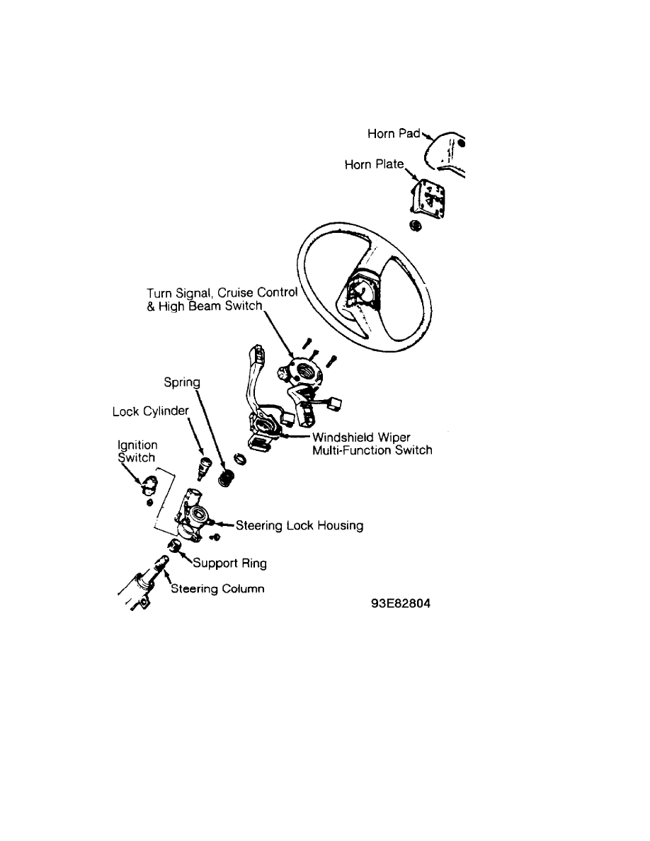
Fig. 1: Identifying Steering Wheel Components (Corrado SLC)
Courtesy of Volkswagen United States, Inc.
STEERING COLUMN SWITCHES
Article Text (p. 2)
1993 Volkswagen EuroVan
For Volkswagen Technical Site
Copyright © 1998 Mitchell Repair Information Company, LLC
Saturday, March 18, 2000 10:37PM
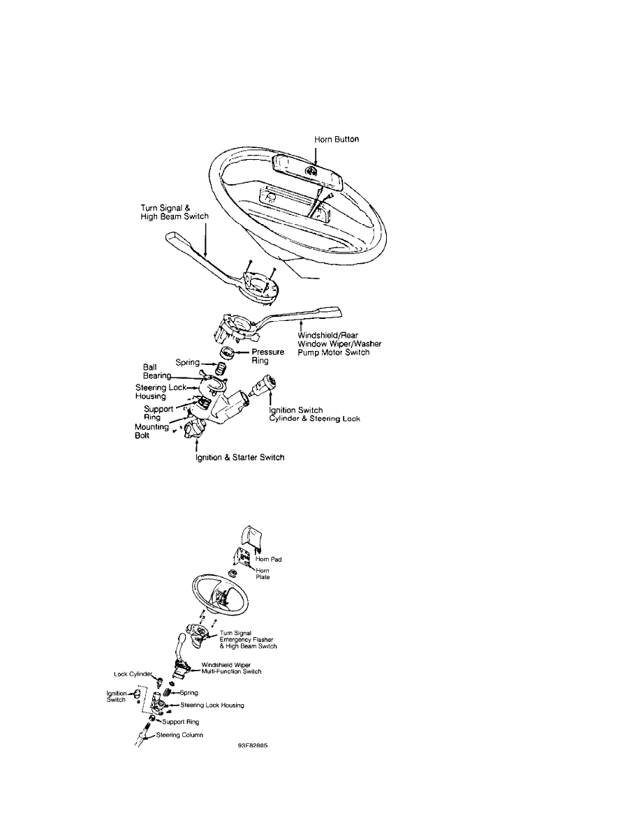
Fig. 2: Identifying Steering Wheel Components (EuroVan)
Courtesy of Volkswagen United States, Inc.
STEERING COLUMN SWITCHES
Article Text (p. 3)
1993 Volkswagen EuroVan
For Volkswagen Technical Site
Copyright © 1998 Mitchell Repair Information Company, LLC
Saturday, March 18, 2000 10:37PM
Fig. 3: Identifying Steering Wheel Components (Fox)
Courtesy of Volkswagen United States, Inc.
Fig. 4: Identifying Steering Wheel Components
(Golf, GTI & Jetta)
Courtesy of Volkswagen United States, Inc.
STEERING COLUMN SWITCHES
Article Text (p. 4)
1993 Volkswagen EuroVan
For Volkswagen Technical Site
Copyright © 1998 Mitchell Repair Information Company, LLC
Saturday, March 18, 2000 10:37PM
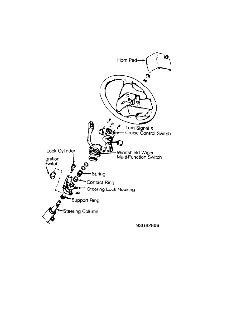
Fig. 5: Identifying Steering Wheel Components (Passat)
Courtesy of Volkswagen United States, Inc.
LOCK CYLINDER
Removal
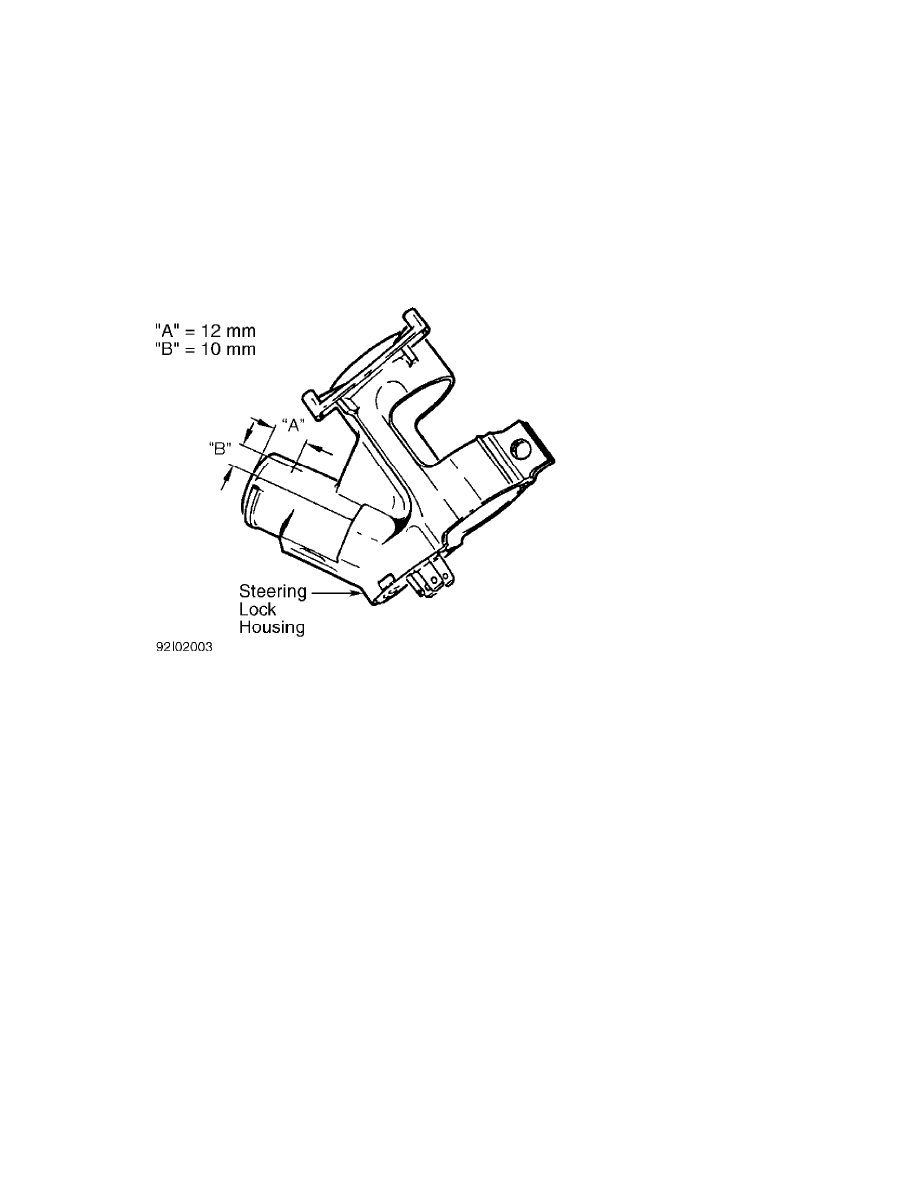
1) Remove steering wheel. Remove combination switch and upper
and lower steering wheel covers. Mark steering lock housing at
intersection of "A" and "B" for hole. See Fig. 6. "A"=12 mm; "B"=10
mm.
2) Drill 3 mm hole into steering lock housing at mark until
lock cylinder stop spring is visible. Hole depth will be approximately
3 mm. Compress stop spring with punch and pull lock cylinder out.
Installation
STEERING COLUMN SWITCHES
Article Text (p. 5)
1993 Volkswagen EuroVan
For Volkswagen Technical Site
Copyright © 1998 Mitchell Repair Information Company, LLC
Saturday, March 18, 2000 10:37PM
1) Insert lock cylinder into steering lock housing. Insert
key into lock cylinder. Push lock cylinder fully into housing while
gently turning key.
2) Install combination switch and upper and lower steering
column covers. Install steering wheel and nut. Tighten steering wheel
nut to specification. See TORQUE SPECIFICATIONS table.
Fig. 6: Drilling Steering Lock Housing
Courtesy of Volkswagen United States, Inc.
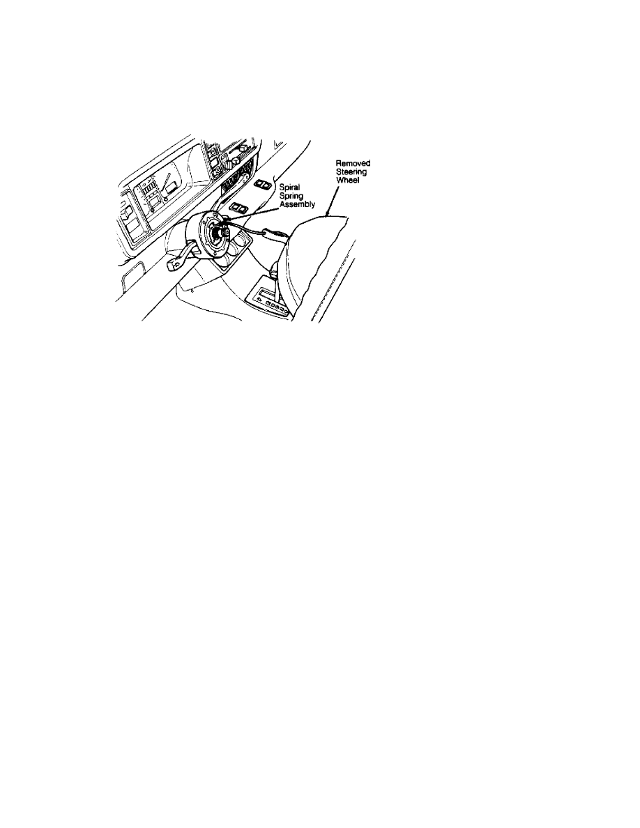
SPIRAL SPRING
Removal (Cabriolet)
Before proceeding, follow air bag service precautions. See
SERVICE PRECAUTIONS in AIR BAG RESTRAINT SYSTEM article in the
ACCESSORIES/SAFETY EQUIPMENT section. Remove steering wheel. See
STEERING WHEEL. Remove knee bar panel and steering column lower trim.
Disconnect 2-pin wiring connector (Green/Black and Green/Red wires) at
base of steering column. Remove 3 spiral spring retaining screws, and
remove spiral spring. See Fig. 7.
STEERING COLUMN SWITCHES
Article Text (p. 6)
1993 Volkswagen EuroVan
For Volkswagen Technical Site
Copyright © 1998 Mitchell Repair Information Company, LLC
Saturday, March 18, 2000 10:37PM
Fig. 7: Removing Spiral Spring Assembly
Courtesy of Volkswagen United States, Inc.
Installation
1) To install spiral spring assembly, reverse removal
procedure. NEW spiral spring assemblies have a locking tab which locks
assembly in its centered position. Locking tab must be removed before
installing new spring assembly.
2) If a spiral spring assembly is reinstalled, it must be
centered. To center, turn spring assembly 4 turns from stop, in either
direction.
3) Reactivate air bag system. See DISABLING & ACTIVATING AIR
BAG SYSTEM. Check air bag indicator lights to ensure system is
functioning properly. See SYSTEM OPERATION CHECK.
STEERING WHEEL
Removal (Cabriolet)
1) Before proceeding, follow air bag service precautions. See
SERVICE PRECAUTIONS in AIR BAG RESTRAINT SYSTEM article in the
ACCESSORIES/SAFETY EQUIPMENT section. Disable air bag system. See
DISABLING & ACTIVATING AIR BAG SYSTEM in AIR BAG RESTRAINT SYSTEM
article in the ACCESSORIES/SAFETY EQUIPMENT section.
2) Turn front wheels to straight-ahead position. Remove air
bag unit. See AIR BAG UNIT in AIR BAG RESTRAINT SYSTEM article in the
ACCESSORIES/SAFETY EQUIPMENT section. Remove steering wheel nut and
spring washer. Mark steering wheel and shaft for reassembly reference.
Remove steering wheel.
Installation
To install, reverse removal procedure. Tighten steering wheel
nut to specification. See TORQUE SPECIFICATIONS table. Check air bag
indicator lights to ensure system is functioning properly.
STEERING WHEEL & HORN PAD
STEERING COLUMN SWITCHES
Article Text (p. 7)
1993 Volkswagen EuroVan
For Volkswagen Technical Site
Copyright © 1998 Mitchell Repair Information Company, LLC
Saturday, March 18, 2000 10:37PM
Removal (Except Cabriolet)
1) Disconnect negative battery cable. Remove screws attaching
horn button assembly/center pad to steering wheel from behind steering
wheel (if equipped).
2) Pull horn button assembly/center pad from steering wheel.
Use a cloth covered screwdriver to pry off horn button assembly/center
pad (if necessary). Disassemble horn button assembly (if necessary).
3) Place springs, contacts, horn or cruise control harness
connectors and screws in order for reassembly reference. Place wheels
in straight-ahead position.
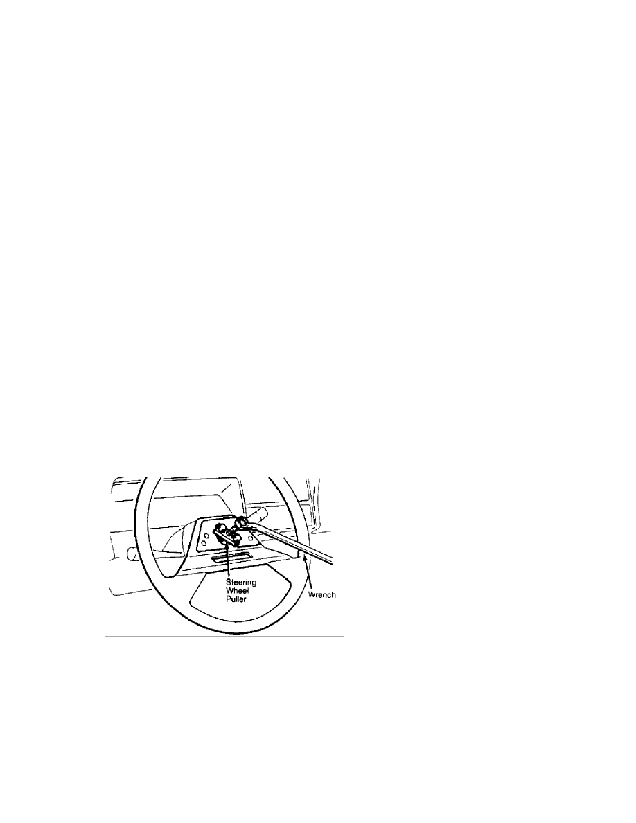
4) Remove steering wheel retaining nut and washer. Mark
steering wheel and shaft for reassembly reference. Using a steering
wheel puller, remove steering wheel. See Fig. 8.
5) Place steering wheel, cruise control set/resume switch
(if equipped), canceling cams, springs and slip rings in order for
reassembly reference.
Installation
1) Coat slip ring contact surfaces with a light electrical
grease. Assemble horn button assembly (if disassembled). Ensure wheels
are in a straight-ahead position.
2) Aligning marks made during removal, place slip ring,
springs, canceling cams, steering wheel, washer and steering wheel
retaining nut on shaft.
3) Tighten steering wheel nut to specification. See TORQUE
SPECIFICATIONS table. To complete installation, reverse removal
procedure.
Fig. 8: Removing Steering Wheel (Typical)
Courtesy of Volkswagen United States, Inc.
STEERING LOCK & IGNITION SWITCH
Removal
1) Remove steering wheel, upper and lower steering column
covers and combination switch. Disconnect ignition switch harness
connectors.
2) Remove clamping washers, spring and contact ring from
steering column. Remove steering lock housing mounting bolt. Remove
steering lock housing from steering column.

STEERING COLUMN SWITCHES
Article Text (p. 8)
1993 Volkswagen EuroVan
For Volkswagen Technical Site
Copyright © 1998 Mitchell Repair Information Company, LLC
Saturday, March 18, 2000 10:37PM
Installation
1) To install, reverse removal procedure. Slide steering lock
housing onto steering column. Install contact ring, spring and
clamping washers onto steering column. Ensure proper operation of
steering lock and ignition switch.
NOTE: On Corrado SLC, pull steering column upward from steering
column tube as far as possible to ensure proper column
position.
2) Install combination switch, upper and lower steering
column covers and steering wheel. Tighten steering wheel nut to
specification. See TORQUE SPECIFICATIONS table.
TORQUE SPECIFICATIONS
TORQUE SPECIFICATIONS TABLE
ÄÄÄÄÄÄÄÄÄÄÄÄÄÄÄÄÄÄÄÄÄÄÄÄÄÄÄÄÄÄÄÄÄÄÄÄÄÄÄÄÄÄÄÄÄÄÄÄÄÄÄÄÄÄÄÄÄÄÄÄ
Application Ft. Lbs. (N.m)
Steering Wheel Nut ................................. 30 (40)
INCH Lbs. (N.m)
Air Bag Unit-To-Steering Wheel Screws .............. 89 (10)
ÄÄÄÄÄÄÄÄÄÄÄÄÄÄÄÄÄÄÄÄÄÄÄÄÄÄÄÄÄÄÄÄÄÄÄÄÄÄÄÄÄÄÄÄÄÄÄÄÄÄÄÄÄÄÄÄÄÄÄÄ
END OF ARTICLE
Wyszukiwarka
Podobne podstrony:
steering column switches
05b1 E70 Steering Column Switch Cluster
05 13 F01 Steering Column Switch Cluster
50 Steering Column
50 Steering Column
50 Steering Column
60 STEERING COLUMN
50 Steering Column
50 Steering Column
steering column
12382 LEGEND LEGEND STEERING COLUMN ISOLATION
50 Steering Column
50 Steering Column
M36e Steering Wheel and Column
Steering Wheel and Column
Steering wheel Control Switch
więcej podobnych podstron