
STEERING COLUMN
1993 Mitsubishi Montero
1993 STEERING
Mitsubishi - Steering Columns
Montero
DESCRIPTION & OPERATION
Steering column consists of a collapsible steering shaft with
lower joint assembly.
REMOVAL & INSTALLATION
STEERING WHEEL & HORN PAD
Removal
Remove screws retaining horn pad. Remove horn pad. Place
reference mark on steering wheel and steering column shaft for
installation reference. Remove steering wheel nut and washer. Using
steering wheel puller, remove steering wheel.
CAUTION: DO NOT hammer on steering wheel during servicing, as it may
damage steering column.
Installation
To install, reverse removal procedure. Ensure reference marks
are aligned. Tighten steering wheel nut to specification. See TORQUE
SPECIFICATIONS.
COMBINATION SWITCH
Removal & Installation
Remove horn pad and steering wheel. See STEERING WHEEL & HORN
PAD under REMOVAL & INSTALLATION. Remove lower heater duct (if
equipped). Remove upper and lower steering column covers. Disconnect
combination switch electrical connectors. Remove screws and
combination switch. To install, reverse removal procedure.
IGNITION SWITCH
Removal & Installation
1) Remove lower instrument cover and heater duct (if
equipped). Remove upper and lower steering column covers. Disconnect
harness connector from ignition switch. Insert ignition key into
cylinder and turn key to ACC position.
2) Using small punch or awl, press down on locks pin located
in cylinder lock housing. Remove ignition switch assembly. To install,
reverse removal procedure.
STEERING COLUMN
CAUTION: Applying excessive pressure or causing impact to steering
shaft during service may cause column to collapse. Before
removing steering column, ensure wheels are in
straight-ahead position. Note steering wheel location for
installation reference.
Removal
1) Remove steering wheel and combination switch (if

necessary). See STEERING WHEEL & HORN PAD and COMBINATION SWITCH under
REMOVAL & INSTALLATION.
2) Remove air ducts and lower instrument panel covers (if
equipped). Disconnect all electrical connections. Disconnect brake
pedal return spring (if equipped).
3) Remove bolts for dust cover at firewall. Remove bolt from
clamp at steering gear. DO NOT separate lower steering shaft from
steering column (if equipped). Remove steering column bolts and remove
steering column.
Installation
To install, reverse removal procedure. Apply sealant to dust
cover bolts before installing. Tighten bolts to specification. See
TORQUE SPECIFICATIONS.
OVERHAUL
STEERING COLUMN
Disassembly
1) Remove steering column from vehicle. See STEERING COLUMN
under REMOVAL & INSTALLATION. Remove clamp bolt from joint assembly.
See Fig. 1. Remove return springs, clevis pin, bolts and bushings from
upper steering column.
2) Remove snap ring, stopper and bearing spacer from upper
steering column. Using ignition switch, unlock steering wheel. Remove
upper steering shaft. Remove dust seal, bushing and upper steering
column.
3) To remove steering lock, use a hacksaw to cut bolts at
steering lock bracket side. Remove steering lock and bracket. Remove
dust cover. Remove column tube clamp and lower steering column.
4) Remove column bushing, column tube and lower steering
shaft. Remove snap ring from lower steering shaft. Remove clip and
bearing from column tube. Remove split pin, tilt lever and snap ring.
Remove lock plate. Remove lower boot, upper boot and dust cover from
joint assembly.
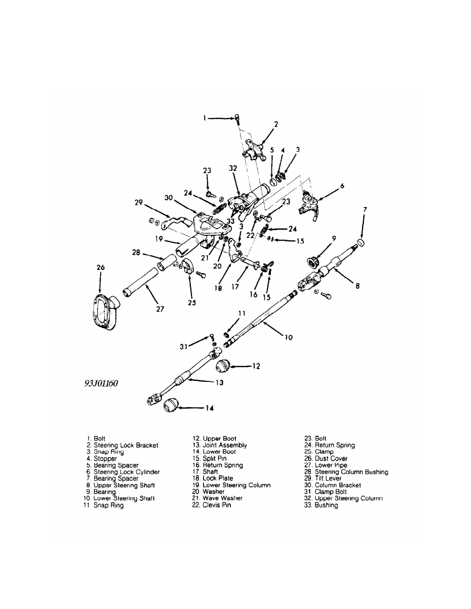
Fig. 1: Exploded View Of Steering Column
Courtesy of Mitsubishi Motor Sales of America.
Inspection
Check for worn or damaged bushings, dust seals, bearings and
mounting plate. Check joint bearing and steering shaft for wear. Check
cover and teeth of plate assembly for damage. Replace components if
necessary.
Reassembly
1) To reassemble, reverse disassembly procedure. Install
upper boot on joint assembly. Install lower boot and dust cover on
joint assembly. Leave boots on shafts without assembling them to
universal joint.
2) Apply multipurpose grease to universal joints of joint
assembly. When installing upper boot, lower boot and dust cover,
ensure arrows on boots align with slit area on yoke. When assembling
lever assembly and plate assembly, apply grease to cam area of lever
assembly, plate clevis pin, and space between clevis pin and return
spring.
3) Apply grease to dust cover grommet, dust seal and upper
steering shaft before installing. Align steering lock with column
boss. Ensure steering lock is operational. Tighten bolt until bolt
head breaks off.
4) When installing upper steering shaft in steering column,
ensure projected area on dust seal aligns with notch of upper steering
column. Apply grease to steering shaft bushings before installing.
5) Assemble upper steering column with lower steering column.
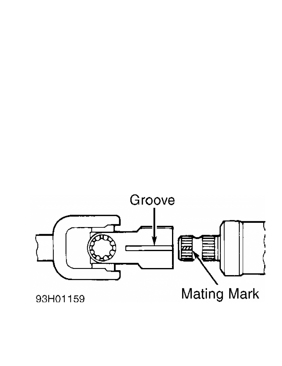
Ensure mating mark on lower steering shaft aligns with yoke groove in
upper steering shaft. See Fig. 2. Apply thread sealant to bolts and
nuts of lower steering column.
6) Install NEW clevis pin until pin is even with lower
steering column. Align mating mark on lower steering shaft with yoke
groove of joint assembly. See Fig. 2.
Fig. 2: Aligning Mating Mark
Courtesy of Mitsubishi Motor Sales of America.
TORQUE SPECIFICATIONS
TORQUE SPECIFICATIONS TABLE
Application Ft. Lbs. (N.m)

Column Bracket Bolts ............................. 16 (22)
Lower Steering Shaft Clamp Bolt ............ 22-25 (30-34)
Steering Gear Clamp Bolt ................... 22-25 (30-34)
Steering Wheel Nut ............................... 29 (40)
Upper Column Side Bolt ........................... 17 (23)
Upper Shaft Assembly Clamp Bolt .................. 13 (18)
INCH Lbs. (N.m)
Dust Cover Bolt ................................... 36 (4)
Horn Pad Bolt ................................ 17-26 (2-3)
Steering Column Tube Clamp ...................... 39 (4.5)
Tilt Lever Bolt ................................. 108 (12)
Wyszukiwarka
Podobne podstrony:
50 Steering Column
50 Steering Column
61 STEERING COLUMN SWITCHES
50 Steering Column
60 STEERING COLUMN
50 Steering Column
50 Steering Column
steering column switches
05b1 E70 Steering Column Switch Cluster
05 13 F01 Steering Column Switch Cluster
12382 LEGEND LEGEND STEERING COLUMN ISOLATION
50 Steering Column
50 Steering Column
M36e Steering Wheel and Column
Steering Wheel and Column
17 steering system
Butterworth Finite element analysis of Structural Steelwork Beam to Column Bolted Connections (2)
więcej podobnych podstron