
EVALUATION OF PVD COATINGS FOR INDUSTRIAL
APPLICATIONS
S. Gulizia, M.Z. Jahedi
CSIRO Manufacturing Science and Technology
CRC for Cast Metal Manufacturing (CAST)
Locked Bag 9, Preston,
VIC 3072 Australia
E.D. Doyle
School of Engineering & Science, Swinburne University
Hawthorn Campus
John Street, Hawthorn,
VIC 3122 Australia
Abstract
During high pressure die casting (HPDC) of aluminium alloys there is a
tendency for the molten alloy to react with the H13 tool steel die, core pins
and inserts. This reaction is commonly referred to as ’soldering’ and involves
inter-diffusion and the formation of intermetallic phases. It is a concern to
high pressure die casters because of down-time due to regular removal of
the soldering, reduced tool life and degradation of product quality. In this
investigation several surface treatments were evaluated for improving the
resistance to soldering of core pins used in HPDC with aluminium alloy.
The surface treatments trialed were gas nitriding, physical vapour deposition
(PVD) TiN, CrN and TiCN, using a specially designed die, made of H13 tool
steel with removable core pins, and a 250 tonne Toshiba HPDC machine. The
effects of draft angle on ’build-up’ were also studied with the view of further
improving casting quality and die life. The results demonstrate that PVD
coatings can improve the resistance to soldering compared to conventional
nitrided and un-coated core pins, however, build-up was observed on all PVD
coatings tested. The least amount of ’build-up’ was observed on PVD coated
881

882
6TH INTERNATIONAL TOOLING CONFERENCE
core pins of 0.5
° draft angle and the extent of build-up was related to the draft
angle and solidification rate adjacent to the gate/core pin interface.
Keywords:
High pressure die casting, PVD coatings, Soldering, Coatings
INTRODUCTION
In recent years a number of studies have been undertaken to characterize
and understand the reaction, namely soldering, that occurs between molten
aluminium and steel dies [1, 2, 3, 4]. These studies revealed that soldering
involves the formation of a brittle intermetallic layer at the cast metal/die in-
terface, which results in a reduction in die life, casting degradation, and more
machine downtime due to the need for die polishing. Argo et al [5] found
that, during high pressure die-casting (HPDC) of zinc alloys, low draft angles
and high temperatures were the most important factors in promoting die sol-
dering. Other researchers [6, 7, 8, 9, 10] have reported significant improve-
ments in die performance with the application of surface treatments such
as Thermo-Reactive Deposition (TRD), Plasma-assisted Chemical Vapour
Deposition (PACVD) and Physical Vapour Deposited (PVD) coatings. With
regard to the latter it has been shown [11] that the application of a PVD
coating on core pins can prevent the formation of intermetallic layers dur-
ing HPDC of aluminium alloy. This paper describes the performance of
Nitrided, PVD TiN, CrN, and TiCN surface treated H13 core pins during
HPDC with aluminium alloy. The results are compared with the performance
of uncoated H13 core pins. The phenomenon of build-up was studied in re-
lationship to draft angle and the effects this may have on the quality of the
casting.
EXPERIMENTAL
CASTING
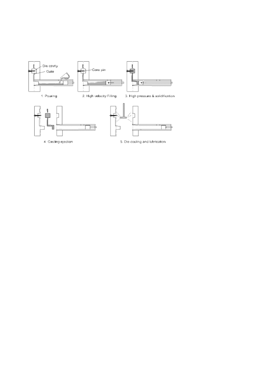
Experiments were carried out on a 250 tonne Toshiba high-pressure die
casting machine. Figure 1 shows the sequence of the events that occur during
a HPDC cycle. A specially designed die with a removable core pin provided
an opportunity to examine the core pin at regular intervals during casting
in order to observe the development of the soldered layer. The core pin
was positioned in front of the chisel gate entry to the die cavity (Fig. 1), in
order to accelerate the growth of soldering. Each core pin was subjected
Evaluation of PVD Coatings for Industrial Applications
883
to 50 HPDC cycles, with each casting cycle lasting 60 seconds. In the final
stage of each casting cycle the metal pressure was held at 78 MPa. The gate
velocity was 50 m/s and the metal temperature was approximately 680℃.
Figure 1.
Schematic representations of accelerated test die and the sequence of events
during each HPDC cycle.
MATERIALS AND COATING
A typical chemical composition for the test core pins and the aluminium
alloy ADC-12 used in this study is given in Table 1. Core pins, 6 mm
diameter by 30 mm long, were manufactured from H13 tool steel, hardened
and tempered to 44–46 HRC. Core pins were cylindrically ground to draft
angles of 0.5°, 1.5°, and 3°, and to a surface roughness (R
a
-value) of 0.8 ±
0.3 µm. Core pins were surface treated with PVD-TiN, CrN, TiCN using a
low voltage electron beam system at a temperature of 450℃ ± 20℃.
EXAMINATION OF CORE PINS
All core pins were optically examined and photographed after 50 HPDC
shots. The soldered layers on the surfaces of the core pins were three di-
mensionally mapped using a novel combination of a surface profilometer

884
6TH INTERNATIONAL TOOLING CONFERENCE
Table 1.
Chemical composition of H13 tool steel and aluminium alloy ADC-12
wt.%
Al
Si
Cu
Fe
Mg
Mn
C
Cr
Mo
V
H13
–
1.05
–
bal
–
–
0.4
5.0
1.35
1.1
ADC-12
bal
11.5
2.8
1.0
0.16
0.2
–
–
–
–
interfaced with computer data acquisition and 3D computer imaging soft-
ware. Prior to mapping, the profilometer was set to zero on an area not
covered by soldering. This point was referred to as the datum point and
all measurements above this point were considered to be the effects of sol-
dering. The profilometer stylus was positioned at one end of the core pin,
so that the stylus could move automatically along the center axis of the
core pin for 30 mm. This length represented the total length of the core pin
that was exposed to the inside of the die cavity. Data was recorded while
the stylus moved over the contour of the soldered layer at a rate of 60 data
points/second, for a period of 60 seconds. Once the stylus reached the end of
the 30 mm length it stopped recording and automatically returned to the start
position. The core pin was then rotated by 30° using a universal-dividing
head. This process was repeated until the entire circumference of the core
pin was mapped. A computer image software package, Matlab
®
was used
to combine all of the data points recorded and form a 3D representation
of the soldered layer, measure its thickness, distribution and volume. The
PVD coating integrity and soldering was characterized using both optical
and Leica S440 scanning electron microscopy.
RESULTS AND DISCUSSION
INFLUENCE OF SURFACE TREATMENT ON SOLDER-
ING IN HPDC
Photographs of the core pins after 50 HPDC cycles in the experimental
die are shown in Fig. 2. It is evident that there is significant soldering of
aluminium alloy on the un-coated and nitrided core pins compared with the
PVD coated pins.
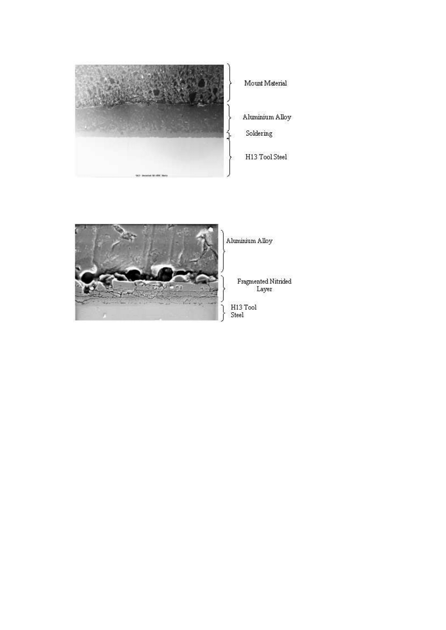
Metallographic analysis of cross-sections of the 1.5° draft core pins re-
vealed the following interesting result, as shown in Fig. 3a – 3c. Fig. 3a

Evaluation of PVD Coatings for Industrial Applications
885
Figure 2.
Photographs of the core pins after 50 HPDC cycles in the experimental die
showing the amount of soldering as a function of the surface modification treatment.
shows that a reaction has taken place between the casting alloy and the H13
substrate resulting in the formation of intermetallic compounds. This is con-
sistent with the results of other observers Sundqvist et al [12] and therefore
falls under the correct description of soldering. Soldering on the nitrided
core pin was different, see Fig. 3b. Although the nitrided layer was frag-
mented, there was no evidence of intermetallic layer formation. However,
there was build-up of aluminium alloy on top of the fragmented nitrided
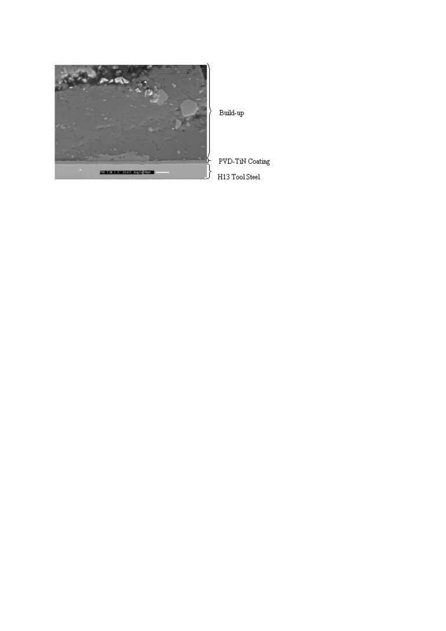
layer. The PVD TiN coated core pin, shown in Fig. 3c shows no evidence
of any intermetallic layer formation and the TiN coating is intact. However,
the micrograph does show the presence of build-up on the TiN coating. This
overall pattern was much the same for both CrN and TiCN. Evidently all the
PVD coated core pins, after 50 HPDC cycles, showed no signs of soldering,
in other words, the PVD coatings were successful in establishing a barrier
between the aluminium alloy and the H13 tool steel, thus preventing the
formation of intermetallic phases.
INFLUENCE OF DRAFT ANGLE ON BUILD-UP WITH
PVD-TIN COATED CORE PINS
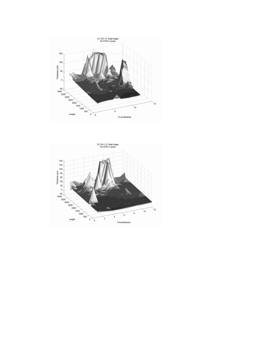
The effect of draft angle on the severity of build-up on PVD coated cores
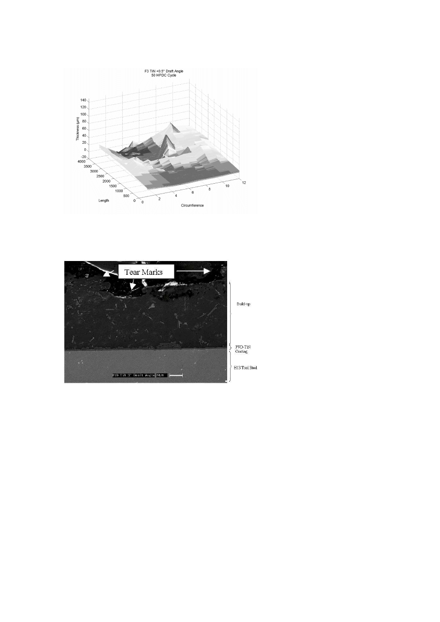
is shown in 3D representation in Fig. 4a – 4c. The PVD-TiN core pin with
the highest draft angle of 3° (Fig. 4a) shows clearly a large area covered
by build-up concentrated to one end of the core pin at a location facing the
chisel gate. The maximum thickness of the build-up with a 3° draft exceeded
150 µm. In contrast, the core pins with the lowest draft angle of 0.5° (Fig. 4c)
886
6TH INTERNATIONAL TOOLING CONFERENCE
Figure 3a.
Cross-section of an un-coated core pin after 50 accelerated HPDC cycles show-
ing the extent of soldering and the presence of an intermetallic compound at the soldering/H13
interface.
Figure 3b.
Cross-section of a Nitrided core pin after 50 accelerated HPDC shots showing
a fragmented nitrided layer.
has the least amount of area covered by build-up, and a much thinner and
more evenly distributed layer not exceeding 40 µm in thickness. The amount
of area covered by build-up for the PVD-TiN coated core pin with 1.5° draft
was in between, see Fig. 4b. This suggests that the low clearance created by
a lower draft angle effectively ’wipes’ and polishes build-up on the surface
of the core pin as the casting is ejected from the die cavity. Evidence of a
Evaluation of PVD Coatings for Industrial Applications
887
Figure 3c.
Cross-section of a PVD-TiN coated core pin after 50 accelerated HPDC shots
showing no intermetallic layer formation but the presence of a built-up layer.
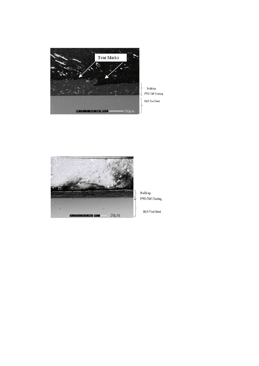
’wiping’ phenomenon can be seen in Fig. 5c. This figure clearly shows a
thin tear-free smoothed layer of build-up on a PVD-TiN coated core pin of
draft angle 0.5°. This is in contrast to the build-up evident on the higher
draft angle PVD-TiN, shown in Figs. 5a and 5b. The latter figures show the
presence of tear marks on the surface of the build-up.
The quality of the cavity produced by the core pin in the aluminium alloy
cast product was also inspected. In each case the bottom half of the cavity
facing the chisel gate, had a rough and porous surface appearance. This in
part, is due to the geometry of the test configuration, that is, having a chisel
gate facing a core pin. This will give rise to a porous skin, which in turn,
provides a fracture path below the cavity surface. This fracture path then
gives rise to the formation of build-up. Clearly if one could improve the
solidification adjacent to the gate/core pin interface, then one could reduce
or even eliminate the build-up on PVD coated core pins.
CONCLUSIONS
The results of this work can be summarised as follows
1. The failure due to soldering of un-coated core pins was related to the
formation of intermetallic layers at the aluminium alloy/H13 tool steel
substrate interface.
888
6TH INTERNATIONAL TOOLING CONFERENCE
Figure 4a.
3D representation of a 3
° draft angle core pin after 50 HPDC shots showing
the area covered and thickness of build-up.
Figure 4b.
3D representation of a 1.5
° draft angle core pin after 50 HPDC shots showing
the area covered and thickness of build-up.
Evaluation of PVD Coatings for Industrial Applications
889
Figure 4c.
3D representation of a 0.5
° draft angle core pin after 50 HPDC shots showing
the area covered and thickness of build-up.
Figure 5a.
Cross-section of a PVD-TiN coated core pin after 50 HPDC shots on a 3
° draft
angle showing presence of tearing on the surface of build-up.
890
6TH INTERNATIONAL TOOLING CONFERENCE
Figure 5b.
Cross-section of a PVD-TiN coated core pin after 50 HPDC shots on a 1.5
°
draft angle showing presence of tearing on the surface of build-up.
Figure 5c.
Cross-section of a PVD-TiN coated core pin after 50 HPDC shots on a 0.5
°
draft angle showing the presence of a tear- free smoothed layer of build-up.

Evaluation of PVD Coatings for Industrial Applications
891
2. Soldering of Gas Nitrided core pins was related to fragmentation of the
nitrided layer.
3. PVD coated core pins showed excellent resistance to soldering. The
mechanism of this resistance was the prevention of intermetallic layer
formation at the aluminium alloy/H13 tool steel interface. However build-
up was found on all PVD coated core pins.
4. The extent of the build-up on the PVD coated core pins was related to the
draft angle. The least build-up was observed on the PVD coated core pins
of 0.5° draft angle. This is due to a ’wiping and polishing’ phenomenon
resulting in lower clearances during ejection of the casting.
5. Build-up could be reduced or eliminated if the solidification and filling
conditions were improved.
ACKNOWLEDGMENTS
This work was funded by the Trust Bank and supported by Nissan Cast-
ing Australia Pty. Ltd. Special thanks to the staff at Nissan, particularly
Graeme Luxford and Ms. J. Law for their support. The authors gratefully
acknowledge the support of Dr. M. T. Murray and Mr. A. Yob for his tech-
nical support. We also thank Surface Technology Coatings, a wholly owned
subsidiary of Sutton Tools, for providing the PVD coatings.
REFERENCES
[1] Y. CHU, P. S. CHENG and R. SHIVPURI, Soldering phenomenon in aluminium die
casting: Possible causes and cures. NADCA Transaction, (1993) Paper No. T93-124
[2] Y. CHU, S. BALASUBRAMANIAM, R. RAJAN and R. SHIVPURI, A study of the
cast alloy/die surface interactions in aluminium die casting. NADCA Transactions,
(1997) Paper No. T97-075
[3] Z. W. CHEN and M. Z. JAHEDI, Die erosion and its effect on soldering formation in
high pressure die casting of aluminium alloys. Materials And Design 20 (1999) p.303.
[4] S. SHANKER and D. APELIAN, Die soldering-A metallurgical analysis of the molten
aluminium/die interface reactions. NADCA Transactions, (1997) Paper No. T97-085
[5] D. ARGO, R. J. BARNHURST and W. WALKINGTON, NADCA sponsored research:
The causes of soldering in zinc die casting. NADCA Transactions, (1997) Paper No.
T97-033
[6] J. M. BIRCH, S. E. BOOTH and B. T. HILL, Prevention of soldering with surface
coating of dies. NADCA Transactions, (1991) Paper No. T91-023

892
6TH INTERNATIONAL TOOLING CONFERENCE
[7] Y. TSUCHIYA, H. KAWAURA, K. HASHIMOTO, H. INAGAKI and T. ARAI, Core
pin failure in aluminum die casting and the effects of surface treatment, NADCA
Transactions, (1997) Paper No. T97-103
[8] T. ARAI, Research and application of carbide and nitride coatings onto aluminium
die casting molds in Japan. NADCA Transactions, (1995) Paper No. T95-102
[9] P. HAIRY and M. RICHARD, Reduction of sticking in pressure die casting by surface
treatment, NADCA Transactions, (1997) Paper No. T97-102
[10] C. PFOHL, A. GEBAUER-TEICHMANN and T. K. RIE, Application of wear-resistant
PACVD coatings in Aluminium diecasting: economical and ecological aspects, Sur-
face and Coatings Technology 112 (1999) 347-350
[11] S. GULIZIA, Z. M. JAHEDI, E. D. DOYLE and Z. W. CHEN, Performance evaluation
of PVD coatings for high pressure die casting. Biennial materials conference of IMEA,
Materials’ 98 (1998)
[12] M. SUNDQVIST, J. BERGSTR ¨
OM and R. WESTERGARD, Transaction of the 17th
international die casting congress, Minneapolis. NA
Wyszukiwarka
Podobne podstrony:
73 1041 1052 PACVD Hard Coatings for Industrial Applications
Evaluation of HS SPME for the analysis of volatile carbonyl
Energetic and economic evaluation of a poplar cultivation for the biomass production in Italy Włochy
Time Series Models For Reliability Evaluation Of Power Systems Including Wind Energy
Evaluating The Use Of The Web For Tourism Marketing
Applications of polyphase filters for bandpass sigma delta analog to digital conversion
64 919 934 New Trends in Thin Coatings for Sheet Metal Forming Tools
2004 Code of Safe Practice for Solid Bulk?rgoesid 171
00 Mechatronics of Electrostatic Microactuators for HD
51 721 736 Evaluation of the Cyclic Behaviour During High Temperature Fatique of Hot Works
Interpretation of Diagnostic Tests for Hepatitis B
Comparative testing and evaluation of hard surface disinfectants
Język angielski What do you think of AIDS victims?gging for money to live
72 1031 1039 Influence of Thin Coatings Deposited by PECVD on Wear and Corrosion Resistance
Hutter, Crisp Implications of Cognitive Busyness for the Perception of Category Conjunctions
Evaluation of in vitro anticancer activities
Kingdom of Denmark Strategy for Arctic 2011 2020
więcej podobnych podstron