Cat.No.P16E-15
Murata
Manufacturing Co., Ltd.
Ceramic Resonators
(CERALOCKr)
Please read rating and
!
CAUTION (for storage, operating, rating, soldering, mounting and handling) in this PDF catalog to prevent smoking and/or burning, etc.
This catalog has only typical specifications. Therefore, you are requested to approve our product specifications or to transact the approval sheet for product specifications before ordering.
!
Note
P16E15.pdf 04.8.27
1
2
3
4
5
6
Chip Type Three Terminals CSTCC/R/E/G/V/W Series
Chip Type Two Terminals CSACV/W Series
MHz Chip Type CSTC Series Packaging
MHz Chip Type CSAC Series Packaging
Lead Type Three Terminals CSTLS Series
Lead Type Two Terminals CSALS Series
MHz Lead Type CSTLS Series Packaging
MHz Lead Type CSALS Series Packaging
Chip Type Two Terminals CSBFB Series
kHz Chip Type CSBFB_J 430-519kHz Notice (Soldering and Mounting)
kHz Chip Type CSBFB_J 700-1250kHz Notice (Soldering and Mounting)
Lead Type Two Terminals CSBLA Series
Utilizing Application Circuits
CERALOCKr and "CERALOCK" in this catalog are
the trademarks of Murata Manufacturing Co., Ltd.
CONTENTS
!
Note
• Please read rating and
!
CAUTION (for storage, operating, rating, soldering, mounting and handling) in this catalog to prevent smoking and/or burning, etc.
• This catalog has only typical specifications because there is no space for detailed specifications. Therefore, please approve our product specifications or transact the approval sheet for product specifications before ordering.
Recycled Paper
Please read rating and
!
CAUTION (for storage, operating, rating, soldering, mounting and handling) in this PDF catalog to prevent smoking and/or burning, etc.
This catalog has only typical specifications. Therefore, you are requested to approve our product specifications or to transact the approval sheet for product specifications before ordering.
!
Note
P16E15.pdf 04.8.27
2
qProduct ID
wFrequency/Capacitance
eStructure/Size
tDesign
uPackaging
CERALOCKr (MHz)
CS
Ceramic Resonators
G
pp
T/V
pp
X
pp
A
T
MHz No capacitance built-in
MHz Built-in Capacitance
LS
CC
CR/CE/CG
CV
CW
Round Lead Type
Cap Chip Type
Small-cap Chip Type
Monolithic Chip Type
Small Monolithic Chip Type
Thickness Shear mode
Thickness Expander mode
Thickness Expander mode (3rd overtone)
Three-digit alphanumerics express
"Individual Specification".
Structure/Size
-B0
-A0
-R0
-R1
Packaging
Product ID
Code
Code
Code
yIndividual Specification
***
Code
Frequency/Capacitance
Design
Individual Specification
Code
(Part Number)
rNominal Center Frequency
Expressed by four-digit alphanumerics. The unit is in hertz (Hz).
Decimal point is expressed by capital letter "
M
".
With standard products, "
yIndividual Specification" is omitted, and
"
uPackage Specification Code" is carried up.
Bulk
Radial Taping H
0
=18mm
Plastic Taping ø=180mm
Plastic Taping ø=330mm
y
***
e
CE
w
T
r
16M0
t
V53
u
-R0
q
CS
pp indicates initial frequency tolerance and load capacity.
Radial taping is applied to lead type and plastic taping to chip type.
y
***
e
FB
w
B
r
500K
t
J58
u
-R1
q
CS
qProduct ID
wFrequency/Capacitance
eStructure/Size
rNominal Center Frequency
tDesign
uPackaging
CERALOCKr (kHz)
CS
Ceramic Resonators
E
pp
J
pp
B
kHz No capacitance built-in
LA
FB
Two-Terminal Lead Type
SMD Type
Area Expansion mode
Area Expansion mode (Closed Type)
Three-digit alphanumerics express
"Individual Specification".
Structure/Size
-B0
-R1
Packaging
Product ID
Code
Code
Code
yIndividual Specification
***
Code
Frequency/Capacitance
Design
Individual Specification
Code
(Part Number)
Expressed by four-digit alphanumerics. The unit is in hertz (Hz).
Capital letter "
K
" following three figures expresses the unit of
"kHz". In case of 1.0MHz (1000kHz) or above, expressed by
three figures and capital letter "
M
" for decimal point.
With standard products, "
yIndividual Specification" is omitted, and
"
uPackage Specification Code" is carried up.
Bulk
Plastic Taping ø=330mm
pp indicates initial frequency tolerance and load capacitance.
o
Part Numbering
!
Note
• Please read rating and
!
CAUTION (for storage, operating, rating, soldering, mounting and handling) in this catalog to prevent smoking and/or burning, etc.
• This catalog has only typical specifications because there is no space for detailed specifications. Therefore, please approve our product specifications or transact the approval sheet for product specifications before ordering.
Please read rating and
!
CAUTION (for storage, operating, rating, soldering, mounting and handling) in this PDF catalog to prevent smoking and/or burning, etc.
This catalog has only typical specifications. Therefore, you are requested to approve our product specifications or to transact the approval sheet for product specifications before ordering.
!
Note
P16E15.pdf 04.8.27
3
1
!
Note
• Please read rating and
!
CAUTION (for storage, operating, rating, soldering, mounting and handling) in this catalog to prevent smoking and/or burning, etc.
• This catalog has only typical specifications because there is no space for detailed specifications. Therefore, please approve our product specifications or transact the approval sheet for product specifications before ordering.
Ceramic Resonators (CERALOCKr)
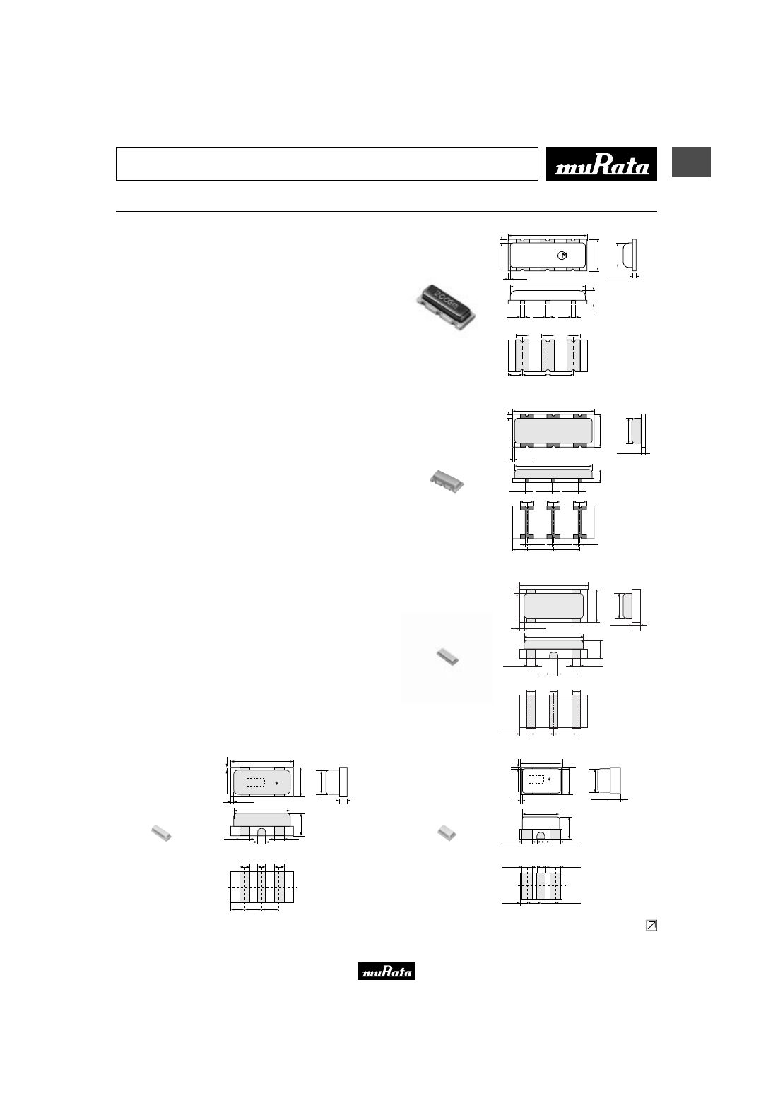
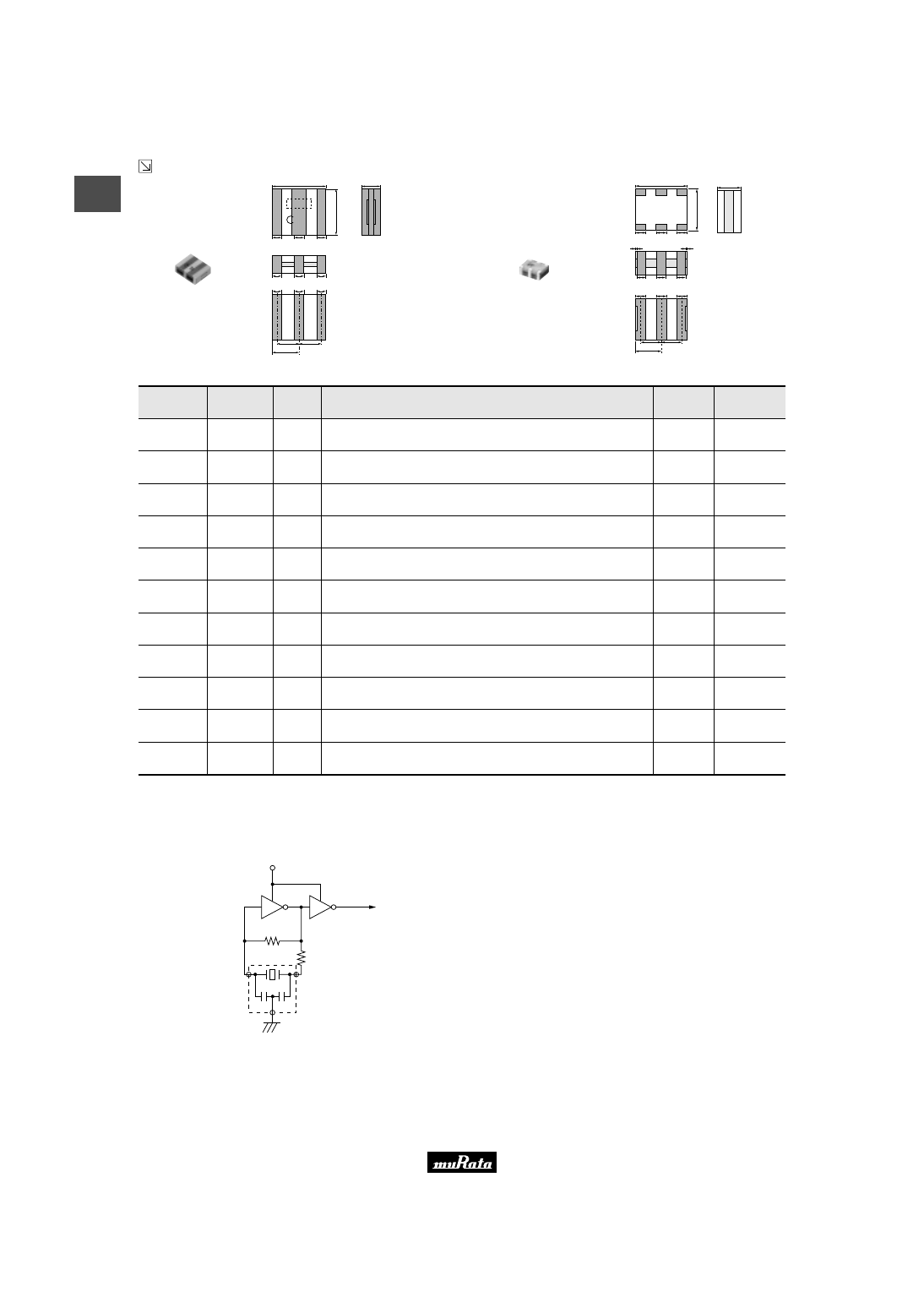
Chip Type Three Terminals CSTCC/R/E/G/V/W Series
Chip "CERALOCK" with built-in load capacitance in an
extremely small package.
MURATA's package technology expertise has enabled the
development of the Chip "CERALOCK" with built-in load
capacitors.
High-density mounting can be realized because of the
small package and the elimination of the need for an
external load capacitor.
■ Features
1. Oscillation circuits do not require external load
capacitors.
2. The series is available in a wide frequency range.
3. The resonators are extremely small and have a low
profile.
4. No adjustment is necessary for oscillation circuits.
■ Applicatons
1. Clock oscillators for microprocessors
2. Electronic control circuits for small electronic
equipment such as hand held video camera
3. Audio-visual applications
(Camcorder, Remote Controller, etc.)
4. Office automation equipments
(DVD, CD-ROM, HDD, FDD, etc.)
5. Automotive electronics
(CSTCC_G_A series, CSTCR_G_B series,
CSTCE_G_A series, CSTCE_V_A series,
CSTCV_X_Q series)
6. Dual Tone Multi Frequency (DTMF) generator for
cordless telephones
0.45
(Ref.)
1.2
±
0.2
6.6 max.
(3)
(2)
(1)
0.3
±
0.3
0.5
±
0.05
2.5
±
0.1
2.5
±
0.1
1.1
±
0.1
7.2
±
0.2
3.0
±
0.2
t
0.45
±
0.3
∗
∗
: EIAJ code
t : 1.75
±
0.05
(2.00—2.99MHz)
t : 1.55
±
0.05
(3.00MHz—)
1.4
±
0.2
1.2
±
0.2
0.45
(Ref.)
0.45
(Ref.)
2.1 max.
(in mm)
CSTCC_G(_A)
2.00-3.99MHz
4.5
±
0.1
∗
4.1 max.
0.8
±
0.1
0.75
±
0.1 1.5
±
0.1
1.5
±
0.1
0.4
±
0.1
0.4
±
0.1
0.4
±
0.1
0.8
±
0.1
0.8
±
0.1
0.4 (ref.)
0.4 (ref.)
0.4 (ref.)
0.4
±
0.05
0.2
±
0.2
0.3
±
0.2
2.0
±
0.1
1.4 max.
(2)
(1)
(3)
1.15
±
0.05
∗
: EIAJ Monthly
Code
(in mm)
CSTCR_G(_B)
4.00-7.99MHz
3.2
±
0.15
1.3
±
0.15
0.50(ref.)
0.50(ref.)
0.50(ref.)
3.0max.
0.10
±
0.10
0.4
±
0.1
0.4
±
0.1
1.2
±
0.1
1.2
±
0.1
(1)
(2)
(3)
0.1
±
0.1
1.1max.
0.4
±
0.1
0.70
±
0.10
0.4
±
0.1
0.4
±
0.1
(in mm)
∗
CSTCE_G(_A)
8.00-12.50MHz
3.2
±
0.15
0.10
±
0.10
0.1
±
0.1
1.3
±
0.15
1.1max.
0.4
±
0.1
0.62(ref.)
0.62(ref.)
0.9
±
0.1
3.0max.
0.6
±
0.10.4
±
0.1 0.6
±
0.1
(1)
(2)
(3)
0.65
±
0.1 0.95
±
0.1 0.95
±
0.1
0.45(ref.)
(in mm)
CSTCE_V(_A)
12.51-20.00MHz
0.52(ref.)
0.41(ref.)
0.52(ref.)
2.0
±
0.15
1.3
±
0.15
0.85
±
0.1
1.1max.
0.10
±
0.10
0.075
±
0.075
0.4
±
0.1
1.85max.
0.5
±
0.1
0.3
±
0.1
0.7
±
0.1
0.7
±
0.1
0.3
±
0.1
0.5
±
0.1
(1)
(2)
(3)
(in mm)
CSTCG_V
20.00-33.86MHz
(Ultra small)
Continued on the following page.
Please read rating and
!
CAUTION (for storage, operating, rating, soldering, mounting and handling) in this PDF catalog to prevent smoking and/or burning, etc.
This catalog has only typical specifications. Therefore, you are requested to approve our product specifications or to transact the approval sheet for product specifications before ordering.
!
Note
P16E15.pdf 04.8.27
4
1
!
Note
• Please read rating and
!
CAUTION (for storage, operating, rating, soldering, mounting and handling) in this catalog to prevent smoking and/or burning, etc.
• This catalog has only typical specifications because there is no space for detailed specifications. Therefore, please approve our product specifications or transact the approval sheet for product specifications before ordering.
Continued from the preceding page.
M
∗
3.7
±
0.2
3
.1
±
0
.2
1.3
±
0.1
(0.7)
(3)
0.4
±
0.2
0.5
0.5
0.5
0.4
±
0.2
0.5
±
0.2
(0.7)
(1)
(0.9)
(2)
1.6
±
0.2
1.85
±
0.3
1.6
±
0.2
(in mm)
Thickness varies
with frequency and
built-in capacitance.
*
: EIAJ code
CSTCV_X_Q
20.01-70.00MHz
2.5
T
0.2
1.4 max.
Thickness varies
with frequency and
built-in capacitance.
*
: EIAJ code
0.5
T
0.2
0.5
T
0.2
0.5
T
0.2
1.0
T
0.2
1.0
T
0.2
1.25
T
0.2
(0.5)
(3)
(0.5)
(1)
(0.5)
(2)
0.05
+0.10
- 0.05
0.05
+0.10
- 0.05
0.4
+0.3
- 0.2
0.4
+0.3
- 0.2
0.4
+0.3
- 0.2
*
2
.0
T
0
.2
(in mm)
CSTCW_X
20.01-70.00MHz
Part Number
Oscillating
Frequency
(MHz)
Initial
Tolerance
(%)
Temp. Stability
(%)
Temperature
Range
(
°
C)
Use
CSTCC_G
2.00 to 3.99
±
0.5
±
0.3
[
±
0.4%:Built-in Capacitance 47pF type within Freq.2.00 to 3.49MHz]
-20 to +80
For consumer
electronics
CSTCC_G_A
2.00 to 3.99
±
0.5
±
0.4
[-0.6% to +0.3%:Built-in Capacitance 47pF type within Freq.2.00 to 3.49MHz]
-40 to +125
For automotive
electronics
CSTCR_G
4.00 to 7.99
±
0.5
±
0.2
-20 to +80
For consumer
electronics
CSTCR_G_B
4.00 to 7.99
±
0.5
±
0.15
-40 to +125
For automotive
electronics
CSTCE_G
8.00 to 12.50
±
0.5
±
0.2
-20 to +80
For consumer
electronics
CSTCE_G_A
8.00 to 12.50
±
0.5
±
0.2
-40 to +125
For automotive
electronics
CSTCE_V
12.51 to 20.00
±
0.5
±
0.3
-20 to +80
For consumer
electronics
CSTCE_V_A
12.51 to 20.00
±
0.5
±
0.3
-40 to +125
For automotive
electronics
CSTCG_V
20.00 to 33.86
±
0.5
±
0.3
-20 to +80
For consumer
electronics
CSTCV_X_Q
20.01 to 70.00
±
0.5
±
0.3
-40 to +125
For automotive
electronics
CSTCW_X
20.01 to 70.00
±
0.5
±
0.2
-20 to +80
For consumer
electronics
Irregular or stop oscillation may occur under unmatched circuit conditions. Please check the actual conditions prior to use.
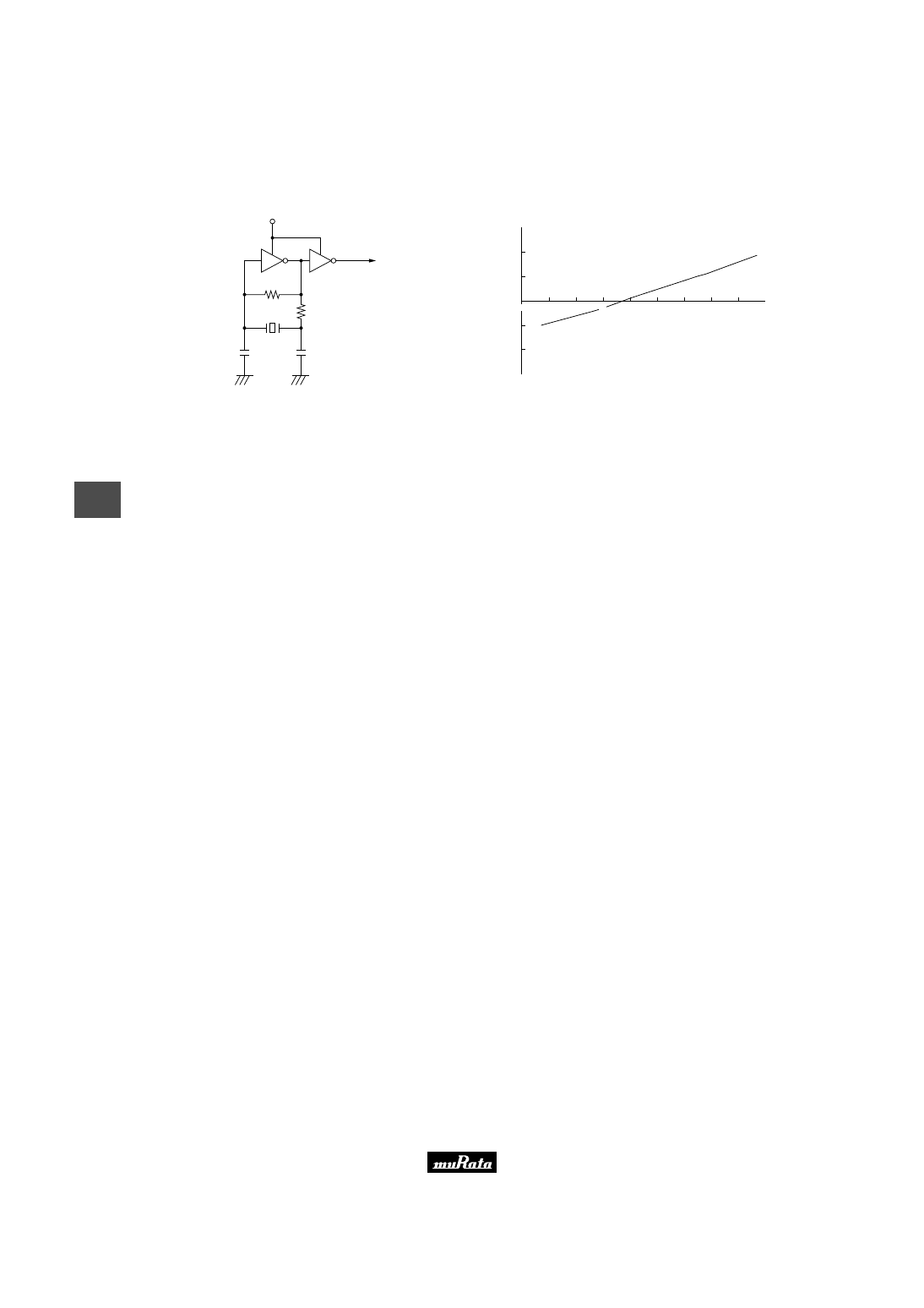
■ Oscillation Frequency Measuring Circuit
Rf
Rd
VDD
C1
C2
To Frequency counter
(1)
(3)
(2)
Please read rating and
!
CAUTION (for storage, operating, rating, soldering, mounting and handling) in this PDF catalog to prevent smoking and/or burning, etc.
This catalog has only typical specifications. Therefore, you are requested to approve our product specifications or to transact the approval sheet for product specifications before ordering.
!
Note
P16E15.pdf 04.8.27
5
1
!
Note
• Please read rating and
!
CAUTION (for storage, operating, rating, soldering, mounting and handling) in this catalog to prevent smoking and/or burning, etc.
• This catalog has only typical specifications because there is no space for detailed specifications. Therefore, please approve our product specifications or transact the approval sheet for product specifications before ordering.
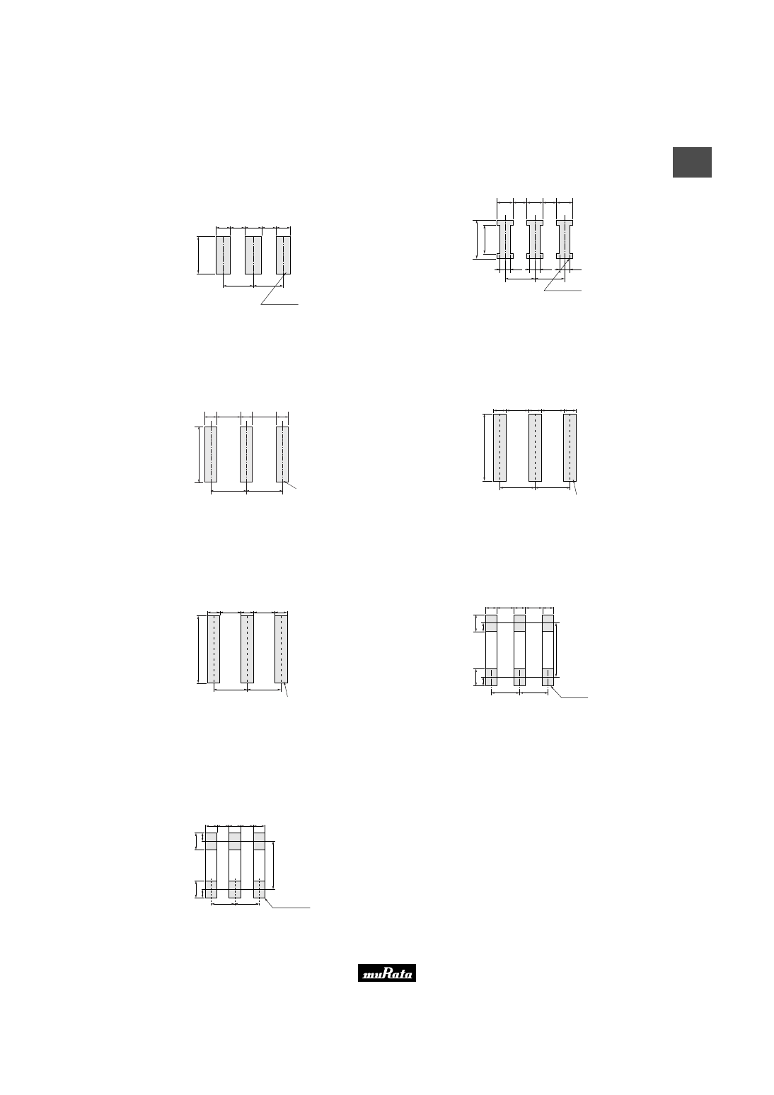
■ Standard Land Pattern Dimensions
CSTCC_G(_A)
3
.8
~
4
.4
1.2
1.2
2.5
2.5
1.4
1.2
1.2
Land Pattern
(in mm)
CSTCR_G(_B)
2
.6
1
.6
0.8
0.4
1.5
1.5
0.4
0.4
0.8
0.8
0.7
0.7
Land Pattern
(in mm)
CSTCE_G(_A)
0.4
1
.9
0
~
2
.1
0
0.4
0.4
0.8
Land Pattern
0.8
1.2
1.2
(in mm)
CSTCE_V(_A)
Land Pattem
0.3
0.3
0.65
0.3
0.65
0.95
0.95
1
.6
(in mm)
CSTCG_V
Land Pattem
0.3
0.3
0.5
0.3
0.5
0.8
0.8
1
.6
(in mm)
CSTCV_X_Q
0.5
1.1
0.5
1.1
0.5
1.6
1.6
1
.0
3
.1
±
0
.2
1
.0
0
.5
0
.5
Land Pattern
(in mm)
CSTCW_X
0.5
0.5
0.5
0.5
1.0
1.0
0
.8
0
.8
2
.0
T
0
.2
0
.3
0
.3
0.5
Land Pattern
(in mm)
Please read rating and
!
CAUTION (for storage, operating, rating, soldering, mounting and handling) in this PDF catalog to prevent smoking and/or burning, etc.
This catalog has only typical specifications. Therefore, you are requested to approve our product specifications or to transact the approval sheet for product specifications before ordering.
!
Note
P16E15.pdf 04.8.27
6
1
!
Note
• Please read rating and
!
CAUTION (for storage, operating, rating, soldering, mounting and handling) in this catalog to prevent smoking and/or burning, etc.
• This catalog has only typical specifications because there is no space for detailed specifications. Therefore, please approve our product specifications or transact the approval sheet for product specifications before ordering.
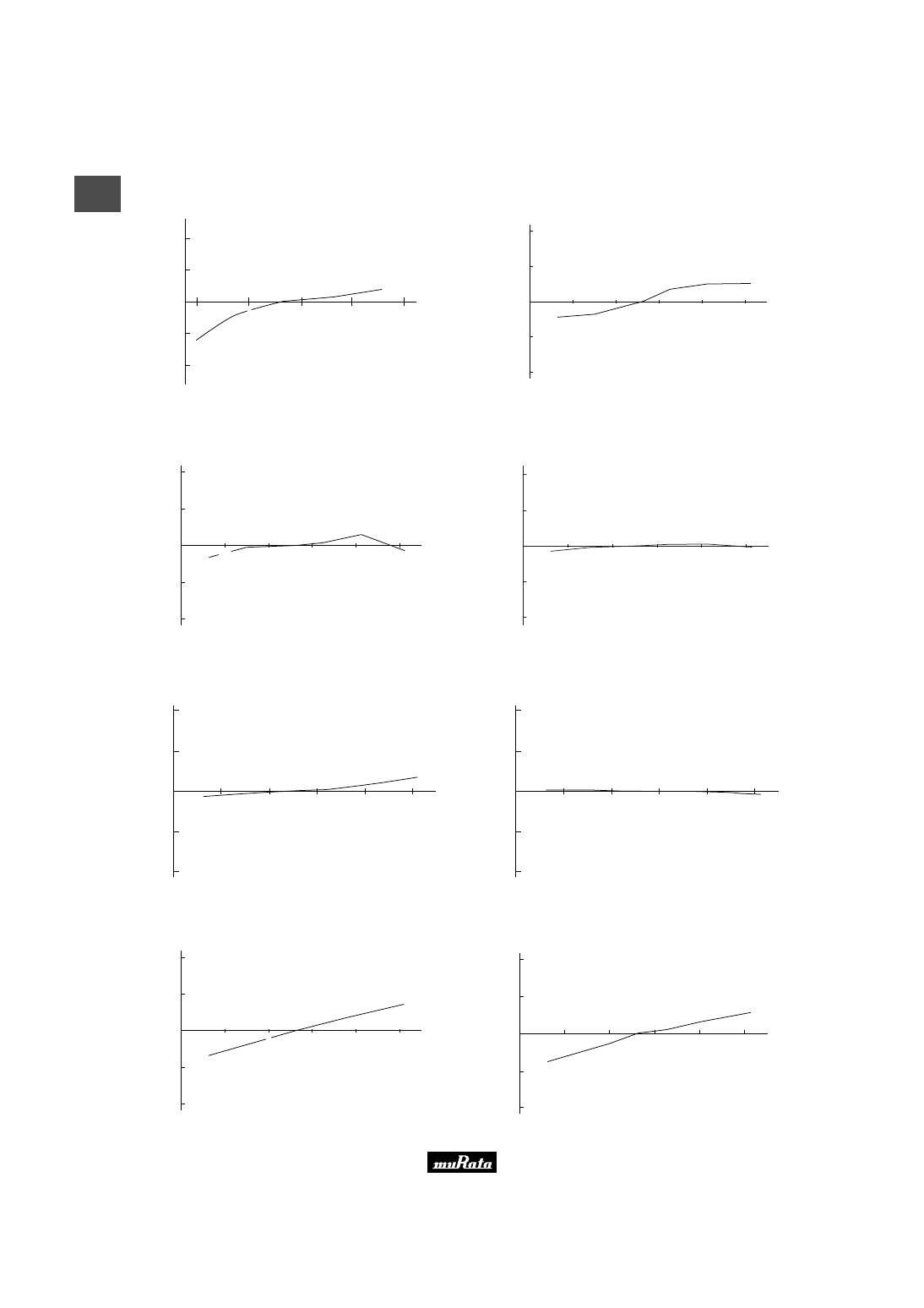
■ Oscillation Frequency Temperature Stability
CSTCC_G
Y
40
80
40
120
W
0.5
W
0.25
0
Y
0.5
Y
0.25
Temperature (˚C)
O
s
c
ill
a
ti
n
g
F
re
q
u
e
n
c
y
S
h
if
t
(%
)
0
CSTCC_G_A
Temperature (
°
C)
O
s
c
ill
a
ti
n
g
F
re
q
u
e
n
c
y
S
h
if
t
(%
)
-40
0
-0.25
-0.50
+0.25
+0.50
0
40
80
120
CSTCR_G(_B)
Temperature (˚C)
O
s
c
ill
a
ti
n
g
F
re
q
u
e
n
c
y
S
h
if
t
(%
)
+
0.50
+
0.25
0
−
0.25
−
0.50
0
40
80
120
−
40
CSTCE_G(_A)
-40
0
40
80
120
Temperature (
°
C)
O
s
c
ill
a
ti
n
g
F
re
q
u
e
n
c
y
S
h
if
t
(%
)
+0.50
+0.25
0
-0.25
-0.50
CSTCE_V(_A)
O
s
c
ill
a
ti
n
g
F
re
q
u
e
n
c
y
S
h
if
t
(%
)
Temperature (
°
C)
-40
+0.50
+0.25
0
-0.25
-0.50
0
80
120
40
CSTCG_V
O
s
c
ill
a
ti
n
g
F
re
q
u
e
n
c
y
S
h
if
t
(%
)
Temperature (
°
C)
-40
+0.50
+0.25
0
-0.25
-0.50
0
80
120
40
CSTCV_X_Q
Temperature (˚C)
O
s
c
ill
a
ti
n
g
F
re
q
u
e
n
c
y
S
h
if
t
(%
)
+
0.50
+
0.25
0
−
0.25
−
0.50
40
80
120
−
40
0
CSTCW_X
40
O
s
c
ill
a
ti
n
g
F
re
q
u
e
n
c
y
S
h
if
t
(%
)
80
120
Y
40
0
0
Y
0.25
W
0.25
Y
0.50
W
0.50
Temperature (
°
C)
Please read rating and
!
CAUTION (for storage, operating, rating, soldering, mounting and handling) in this PDF catalog to prevent smoking and/or burning, etc.
This catalog has only typical specifications. Therefore, you are requested to approve our product specifications or to transact the approval sheet for product specifications before ordering.
!
Note
P16E15.pdf 04.8.27
7
2
!
Note
• Please read rating and
!
CAUTION (for storage, operating, rating, soldering, mounting and handling) in this catalog to prevent smoking and/or burning, etc.
• This catalog has only typical specifications because there is no space for detailed specifications. Therefore, please approve our product specifications or transact the approval sheet for product specifications before ordering.
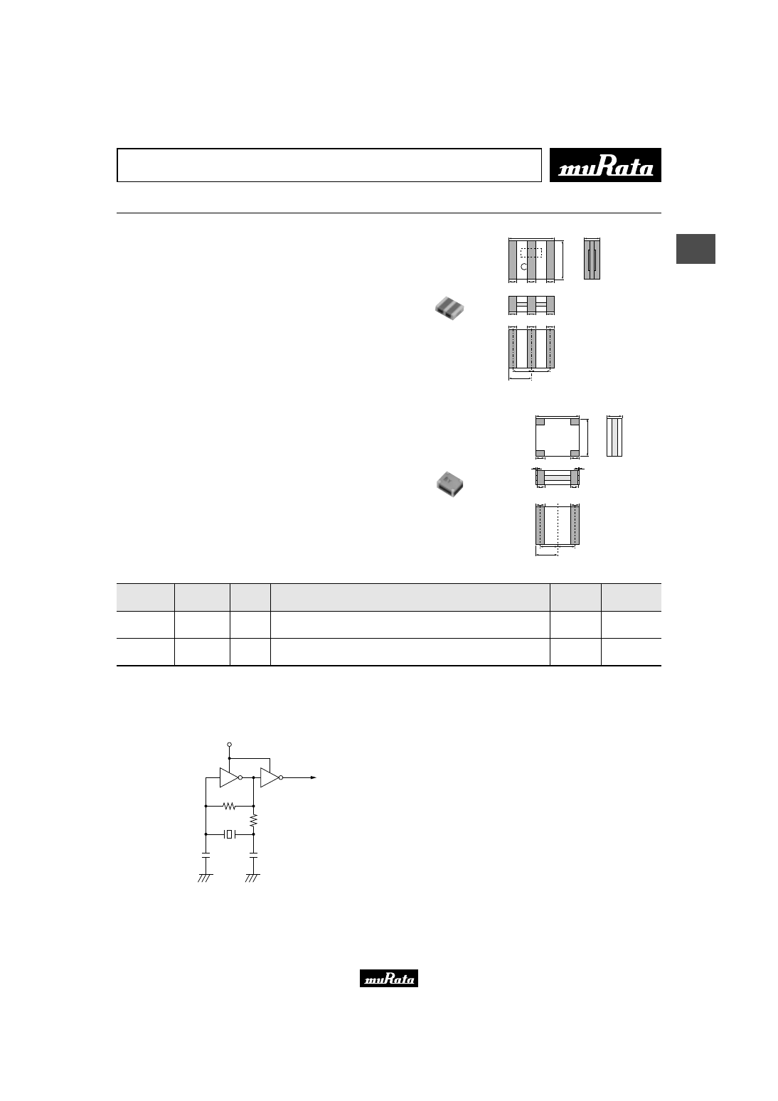
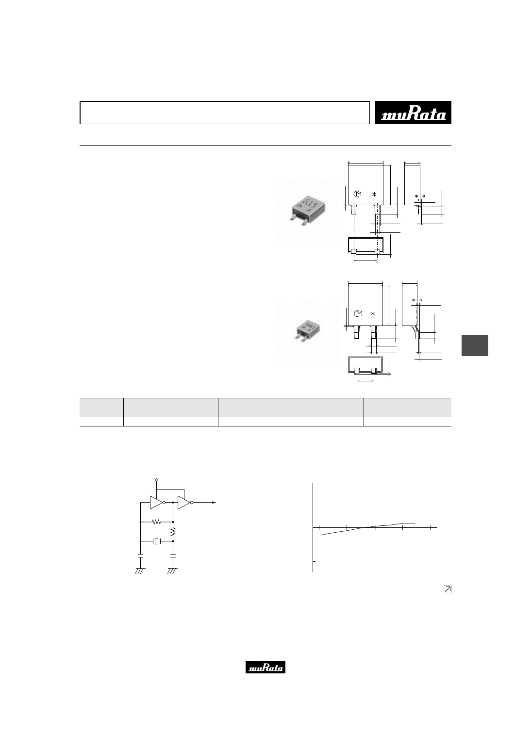
Ceramic Resonators (CERALOCKr)
Chip Type Two Terminals CSACV/W Series
A wide range of chip "CERALOCK" is now available.
This diverse series owes its development to MURATA's
package technology expertise and original mass
production techniques. It enables high-density
mounting and further miniaturization of electronic
equipment.
■ Features
1. The series is available in a wide frequency range.
2. The resonators are extremely small and have a low
profile (CSACW series).
3. No adjustment is necessary for oscillation circuits.
■ Applications
1. Clock oscillators for microprocessors
2. Electronic control circuits for small electronic
equipment
3. Automotive electronics (CSACV_X_Q series)
M
∗
∗
3.7
±
0.2
3
.1
±
0
.2
1.3
±
0.1
(0.5)
(3)
0.4
±
0.2
0.5
0.5
0.5
0.4
±
0.2
0.5
±
0.2
(0.5)
(1)
(0.5)
(2)
1.6
±
0.2
1.85
±
0.3
1.6
±
0.2
Terminal (1) and (3) are
interchangeable.
Terminal (2) should be soldered
only to fix the resonator onto P.C.B.
Terminal (2) should be electrically
froating so it cannot be connected
anywhere.
: EIAJ Monthly Code
(in mm)
Thickness varies
with frequency.
CSACV_X_Q
20.01-70.00MHz
2.5
T
0.2
1.2 max.
Thickness varies
with frequency.
*
: EIAJ code
0.5
T
0.2
0.5
T
0.2
1.0
T
0.2
1.0
T
0.2
1.25
T
0.2
(0.5)
(0.5)
0.05
+0.10
- 0.05
0.05
+0.10
- 0.05
0.4
+0.3
- 0.2
0.4
+0.3
- 0.2
*
2
.0
T
0
.2
(in mm)
CSACW_X
20.01-70.00MHz
Part Number
Oscillating
Frequency
(MHz)
Initial
Tolerance
(%)
Temp. Stability
(%)
Temperature
Range
(
°
C)
Use
CSACV_X_Q
20.01 to 70.00
±
0.5
±
0.3
-40 to +125
For automotive
electronics
CSACW_X
20.01 to 70.00
±
0.5
±
0.2
-20 to +80
For consumer
electronics
Irregular or stop oscillation may occur under unmatched circuit conditions. Please check the actual conditions prior to use.
■ Oscillation Frequency Measuring Circuit
Rf
Rd
VDD
CL2
CL1
To Frequency counter
Please read rating and
!
CAUTION (for storage, operating, rating, soldering, mounting and handling) in this PDF catalog to prevent smoking and/or burning, etc.
This catalog has only typical specifications. Therefore, you are requested to approve our product specifications or to transact the approval sheet for product specifications before ordering.
!
Note
P16E15.pdf 04.8.27
8
2
!
Note
• Please read rating and
!
CAUTION (for storage, operating, rating, soldering, mounting and handling) in this catalog to prevent smoking and/or burning, etc.
• This catalog has only typical specifications because there is no space for detailed specifications. Therefore, please approve our product specifications or transact the approval sheet for product specifications before ordering.
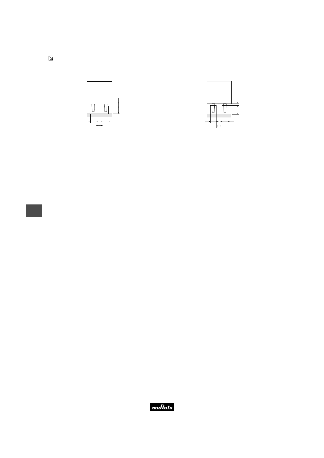
■ Standard Land Pattern Dimensions
CSACV_X_Q
0.5
1.1
0.5
1.1
0.5
1.6
1.6
1
.0
3
.1
±
0
.2
1
.0
0
.5
0
.5
Land Pattern
(in mm)
CSACW_X
0.5
0.5
2.0
0
.8
0
.8
2
.0
T
0
.2
0
.3
0
.3
Land Pattern
(in mm)
■ Oscillation Frequency Temperature Stability
CSACV_X_Q
Temperature (˚C)
O
s
c
ill
a
ti
n
g
F
re
q
u
e
n
c
y
S
h
if
t
(%
)
+
0.50
+
0.25
0
−
0.25
−
0.50
40
80
120
−
40
0
CSACW_X
40
Temperature (
°
C)
O
s
c
ill
a
ti
n
g
F
re
q
u
e
n
c
y
S
h
if
t
(%
)
80
120
Y
40
0
0
Y
0.25
W
0.25
Y
0.50
W
0.50
Please read rating and
!
CAUTION (for storage, operating, rating, soldering, mounting and handling) in this PDF catalog to prevent smoking and/or burning, etc.
This catalog has only typical specifications. Therefore, you are requested to approve our product specifications or to transact the approval sheet for product specifications before ordering.
!
Note
P16E15.pdf 04.8.27
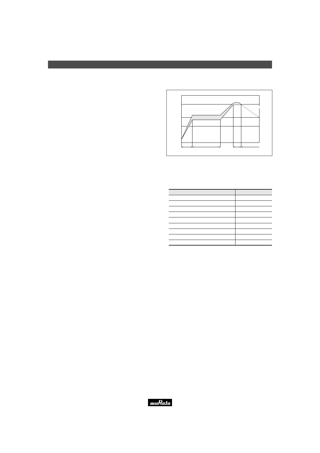
One heat stress, shown in the profile at right, is applied to
resonator; then, after being placed in natural conditions
for 1 hour, the resonator is measured.
1. Pre-heating conditions should be +140 to +160
°
C for
60 to 120 seconds. Ascending time up to +150
°
C
should be longer than 30 seconds.
2. Heating conditions should be within 20 seconds at
+230
°
C min., but peak temperature should be Iower
than +240
°
C.
1. Soldering Conditions
(1) Reflow
HCFC, Isopropanol, Tap water, Demineralized water,
Cleanthrough750H, Pine alpha 100S, Techno care FRW
Some series do not withstand washing.
Please check the list at right before use.
2. Wash
(1) Cleaning Solvents
dT<=60
°
C (dT=Component-solvent)
*1 ex. In case the component at +90
°
C immerses into
cleaning solvent at +60
°
C, then dT=30
°
C.
(2) Temperature Difference : dT *1
5 minutes max. by air blow at +80
°
C max.
(4) Drying
1. Total washing time should be within 10 minutes.
2. Please insure the component is thoroughly evaluated
in your application circuit.
3. The component may be damaged if it is washed with
chlorine, petroleum, or alkali cleaning solvent.
(5) Others
1. Ultrasonic Wash
1 minute max. in above solvent at +60
°
C max.
(Frequency : 28kHz, Output : 20W/L)
2. Immersion Wash
5 minutes max. in above solvent at +60
°
C max.
3. Shower or Rinse Wash
5 minutes max. in above solvent at +60
°
C max.
(3) Conditions
Soldering iron of +270
±
5
°
C should be placed 0.5mm
above electrode of resonator. Melting solder through
soldering iron should be applied to electrode for 3
±
1
seconds; then, after being placed in natural conditions for
24 hour, the resonator should be measured.
(2) Soldering Iron
T
e
m
p
e
ra
tu
re
(
°
C
)
230
Pre-heating
(in air)
Soldering Peak Temperature 240
°
C max.
30 sec. min.
60 to 120 sec.
20 sec. max. 120 sec. min.
150
100
Gradual Cooling
(in air)
CSTCC (Except 2.00 - 3.49MHz)
CSTCV
CSACV
CSTCR
CSTCC (Only 2.00 - 3.49MHz)
CSTCW
CSACW
CSTCE
CSTCG
Series
Wash
Available
Available
Available
Not Available
Not Available
Not Available
Not Available
Not Available
Not Available
∗
All automotive types are available.
MHz Chip Type Notice (Soldering and Mounting)
9
2
!
Note
• Please read rating and
!
CAUTION (for storage, operating, rating, soldering, mounting and handling) in this catalog to prevent smoking and/or burning, etc.
• This catalog has only typical specifications because there is no space for detailed specifications. Therefore, please approve our product specifications or transact the approval sheet for product specifications before ordering.
Please read rating and
!
CAUTION (for storage, operating, rating, soldering, mounting and handling) in this PDF catalog to prevent smoking and/or burning, etc.
This catalog has only typical specifications. Therefore, you are requested to approve our product specifications or to transact the approval sheet for product specifications before ordering.
!
Note
P16E15.pdf 04.8.27

MHz Chip Type Notice
10
2
!
Note
• Please read rating and
!
CAUTION (for storage, operating, rating, soldering, mounting and handling) in this catalog to prevent smoking and/or burning, etc.
• This catalog has only typical specifications because there is no space for detailed specifications. Therefore, please approve our product specifications or transact the approval sheet for product specifications before ordering.
■ Notice (Storage and Operating Conditions)
CSTCC_G
Please do not apply excess mechanical stress to the
component and terminals during soldering.
The component is recommended for use with placement
machines which employ optical placement capabilities.
The component might be damaged by excessive
mechanical force. Please make sure to evaluate by
using placement machines before going into mass
production. Do not use placement machines which
utilize mechanical positioning. Please contact Murata
for details beforehand.
1. CSTCC_G (2.00MHz-3.49MHz)
Conformal coating or washing of the component is
not acceptable because it is not hermetically
sealed.
2. CSTCC_G (3.50MHz-10.0MHz)
Conformal coating of the component is acceptable.
However, the resin material, curing temperature,
and other process conditions should be evaluated
to confirm that stable electrical characteristics
are maintained.
■ Notice (Storage and Operating Conditions)
CSTCR_G/CSTCE_G/CSTCE_V/CSTCG_V
Please do not apply excess mechanical stress to the
component and terminals during soldering.
Conformal coating or washing of the component is not
acceptable because it is not hermetically sealed.
The component is recommended for use with placement
machines which employ optical placement capabilities.
The component might be damaged by excessive mechanical
force. Please make sure to evaluate by using placement
machines before going into mass production. Do not use
placement machines which utilize mechanical positioning.
Please contact Murata for details beforehand.
■ Notice (Storage and Operating Conditions)
CSTCC_G_A/CSTCR_G_B/CSTCE_G_A/CSTCE_V_A
Please do not apply excess mechanical stress to the
component and terminals during soldering.
Conformal coating of the component is acceptable.
However, the resin material, curing temperature, and
other process conditions should be evaluated to
confirm that stable electrical characteristics are
maintained.
The component is recommended for use with placement
machines which employ optical placement capabilities.
The component might be damaged by excessive mechanical
force. Please make sure to evaluate by using placement
machines before going into mass production. Do not use
placement machines which utilize mechanical positioning.
Please contact Murata for details beforehand.
■ Notice (Storage and Operating Conditions)
CSTCV_X_Q/CSACV_X_Q
Please do not apply excess mechanical stress to the
component and terminals during soldering.
Conformal coating of the component is acceptable.
However, the resin material, curing temperature, and
other process conditions should be evaluated to
confirm that stable electrical characteristics are
maintained.
The component is recommended for use with placement
machines which employ optical placement capabilities.
In some cases, placement machines which utilize
mechanical positioning may apply excessive mechanical
force which might result in damage to the ceramic
resonator. Please contact Murata before mounting this
product using placement machines which use mechanical
positioning.
Please read rating and
!
CAUTION (for storage, operating, rating, soldering, mounting and handling) in this PDF catalog to prevent smoking and/or burning, etc.
This catalog has only typical specifications. Therefore, you are requested to approve our product specifications or to transact the approval sheet for product specifications before ordering.
!
Note
P16E15.pdf 04.8.27

MHz Chip Type Notice
11
2
!
Note
• Please read rating and
!
CAUTION (for storage, operating, rating, soldering, mounting and handling) in this catalog to prevent smoking and/or burning, etc.
• This catalog has only typical specifications because there is no space for detailed specifications. Therefore, please approve our product specifications or transact the approval sheet for product specifications before ordering.
■ Notice (Storage and Operating Conditions)
CSTCW_X/CSACW_X
Please do not apply excess mechanical stress to the
component and terminals during soldering.
Conformal coating or washing of the component is not
acceptable because it is not hermetically sealed.
■ Notice (Rating)
The component may be damaged if excess mechanical
stress is applied.
■ Notice (Handling)
"CERALOCK" may stop oscillating or oscillate
irregularly under improper circuit conditions.
Please read rating and
!
CAUTION (for storage, operating, rating, soldering, mounting and handling) in this PDF catalog to prevent smoking and/or burning, etc.
This catalog has only typical specifications. Therefore, you are requested to approve our product specifications or to transact the approval sheet for product specifications before ordering.
!
Note
P16E15.pdf 04.8.27
MHz Chip Type CSTC Series Packaging
12
2
!
Note
• Please read rating and
!
CAUTION (for storage, operating, rating, soldering, mounting and handling) in this catalog to prevent smoking and/or burning, etc.
• This catalog has only typical specifications because there is no space for detailed specifications. Therefore, please approve our product specifications or transact the approval sheet for product specifications before ordering.
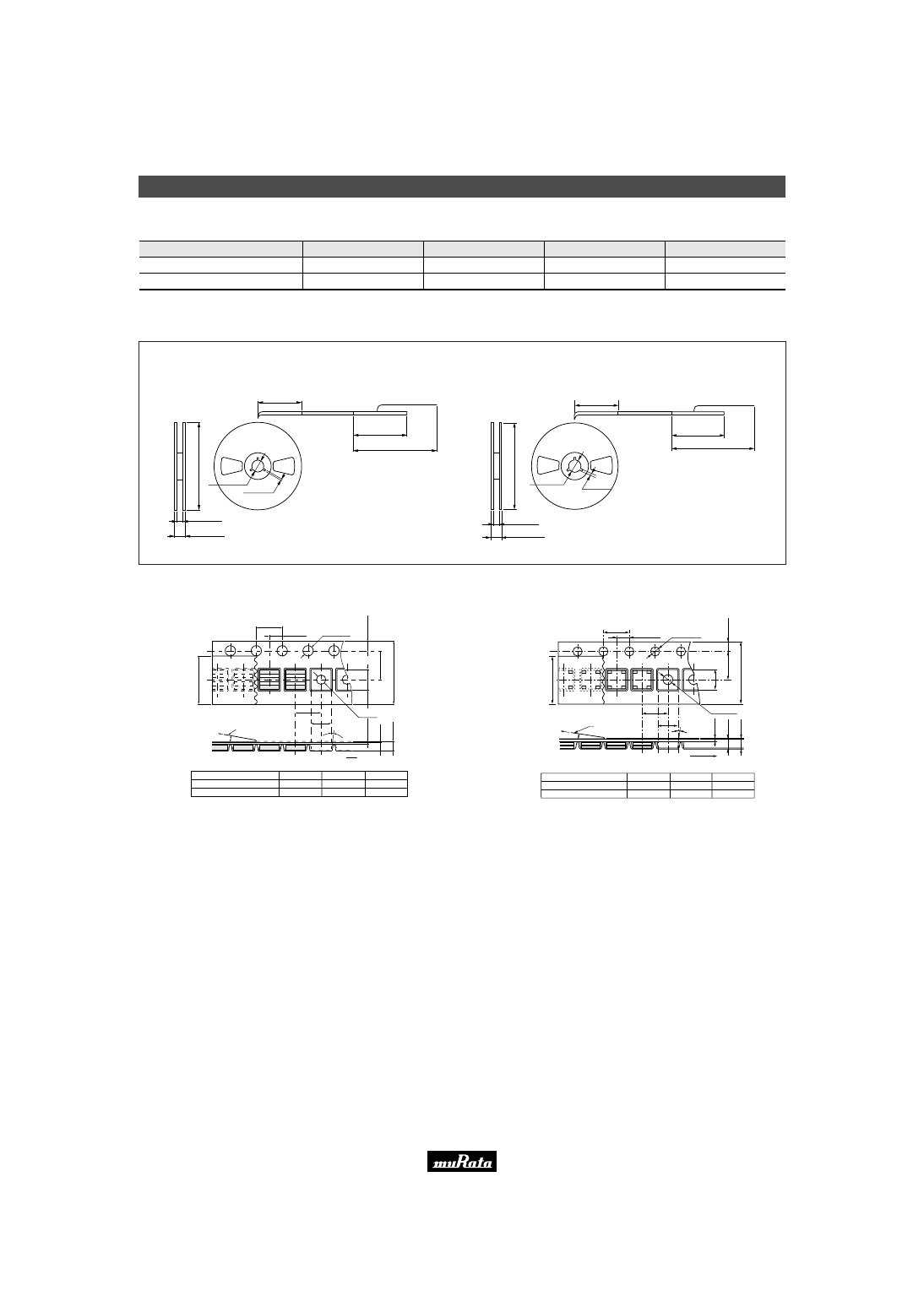
■ Minimum Quantity
(in mm)
a
b
CSTCC_G
CSTCC_G_A
CSTCR_G
CSTCR_G_B
CSTCE_G
CSTCE_G_A
CSTCE_V
CSTCE_V_A
CSTCV_X_Q
CSTCW_X
CSTCG_V
Part Number
Plastic Tape ø180mm
Plastic Tape ø330mm
Bulk
Dimensions
2,000
2,000
3,000
3,000
3,000
3,000
3,000
3,000
2,000
3,000
3,000
6,000
6,000
9,000
9,000
9,000
9,000
9,000
9,000
6,000
9,000
9,000
500
500
500
500
500
500
500
500
500
500
500
a
a
a
a
b
b
b
b
a
b
b
(ø
1
8
0
)
17.0
±
1.0
ø13.0
±
0.2
2.0
±
0.5
160-190
Trailer
Leader
Empty
400-560
Cover Film
Components
Trailer
160-190
Empty
160 min.
Empty
160 min.
400-560
Cover Film
Leader
Empty Components
ø13.0
±
0.2
2.0
±
0.5
+1.0
–0
9.0
13.0
±
1.0
(pcs.)
c Dimensions of Reel
The order quantity should be an integral multiple of the "Minimum Quantity" shown above.
13.0
+1.0
0
0 –
1
.5
(ø
1
8
0
)
0 –
1
.5
■ Dimensions of Taping
CSTCC_G(_A) less than 3.00MHz
(in mm)
4.0
±
0.1
2.0
±
0.05
+0.3
-0.0
ø1.55
±
0.05
ø1.5
1
.7
5
±
0
.1
5
.5
±
0
.0
5
1
2
.0
±
0
.2
7
.6
±
0
.1
4.0
±
0.1
(9
.5
)
3.3
±
0.1
The cover film peel strength force 0.1 to 0.7N
The cover film peel speed 300mm/min.
Cover film
10˚
3˚max.
1
.8
5
±
0
.0
5
0
.3
±
0
.0
5
(2
.4
5
m
a
x
.)
Direction of Feed
(3
)
(2
)
(1
)
CSTCC_G(_A) more than 3.00MHz
(in mm)
4.0
±
0.1
2.0
±
0.05
+0.3
-0.0
φ
1.55
±
0.05
φ
1.5
1
.7
5
±
0
.1
5
.5
±
0
.0
5
1
2
.0
±
0
.2
7
.6
±
0
.1
4.0
±
0.1
(9
.5
)
(1
)
(2
)
(3
)
3.3
±
0.1
The cover film peel strength force 0.1 to 0.7N
The cover film peel speed 300mm/min.
Cover film
10˚
3˚max.
1
.6
5
±
0
.0
5
0
.3
±
0
.0
5
(2
.2
5
m
a
x
.)
Direction of Feed
Continued on the following page.
Please read rating and
!
CAUTION (for storage, operating, rating, soldering, mounting and handling) in this PDF catalog to prevent smoking and/or burning, etc.
This catalog has only typical specifications. Therefore, you are requested to approve our product specifications or to transact the approval sheet for product specifications before ordering.
!
Note
P16E15.pdf 04.8.27
MHz Chip Type CSTC Series Packaging
13
2
!
Note
• Please read rating and
!
CAUTION (for storage, operating, rating, soldering, mounting and handling) in this catalog to prevent smoking and/or burning, etc.
• This catalog has only typical specifications because there is no space for detailed specifications. Therefore, please approve our product specifications or transact the approval sheet for product specifications before ordering.
Continued from the preceding page.
■ Dimensions of Taping
CSTCR_G(_B)
(in mm)
4.0
±
0.1
2.0
±
0.05
(9
.5
)
4.0
±
0.1
(3
)
(2
)
(1
)
ø1.5
W
0.1
Y
0
ø1.5
W
0.1
Y
0
1
2
.0
±
0
.2
5
.5
±
0
.0
5
1
.7
5
±
0
.1
4
.7
±
0
.1
0
.3
±
0
.0
5
1
.2
5
±
0
.0
5
(1
.8
5
m
a
x
.)
2.2
±
0.1
Direction of Feed
3˚ max.
10˚
Cover Film
The cover film peel strength force 0.1 to 0.7N
The cover film peel speed 300mm/min.
CSTCE_G(_A)
(in mm)
2.0
±
0.05
4.0
±
0.1
3
°
max.
3
.5
±
0
.0
5
8
.0
±
0
.2
1
.7
5
±
0
.1
0
.2
5
±
0
.0
5
0
.9
0
±
0
.1
0
(1
.3
0
m
a
x
.)
10
°
(5
.2
)
Cover Film
Direction of Feed
The cover film peel strength force 0.1 to 0.7N
The cover film peel speed 300mm/min.
4.0
±
0.1
1.50
±
0.1
ø1.5
-0.0
+0.1
ø1.0
-0.0
+0.2
3
.4
0
±
0
.1
(3
)
(2
)
(1
)
CSTCE_V(_A)
Dimensions of Carrier Tape
(in mm)
4.0
±
0.1
Cover Film
4.0
±
0.1
2.0
±
0.05
8
.0
±
0
.2
ø1.5
+0.1
-0.0
ø1.0
+0.1
-0.0
3
.5
±
0
.0
5
1
.7
5
±
0
.1
3
.4
5
±
0
.1
Direction of Feed
0
.2
5
±
0
.0
5
(1
.4
0
m
a
x
.)
1
.1
0
±
0
.0
5
3˚ max.
1.50
±
0.1
The cover film peel strength force 0.1 to 0.7N
The cover film peel speed 300mm/min.
10˚
(9
.5
)
(2
)
(3
)
(1
)
CSTCG_V
(in mm)
4.0
±
0.1
Dimensions of Carrier Tape
Cover Film
4.0
±
0.1
2.0
±
0.05
8
.0
±
0
.2
ø1.5
+0.1
-0.0
ø1.0
+0.1
-0.0
3
.5
±
0
.0
5
1
.7
5
±
0
.1
2
.2
±
0
.0
5
Direction of Feed
0
.2
5
±
0
.0
5
(1
.3
0
m
a
x
.)
1
.0
0
±
0
.0
5
3˚ max.
1.45
±
0.1
The cover film peel strength force 0.1 to 0.7N
The cover film peel speed 300mm/min.
10˚
(5
.2
)
(2
)
(3
)
(1
)
CSTCV_X_Q
(in mm)
Thickness of CERALOCK
r
∗
1,
∗
2 : Dimensions vary with product thickness of CERALOCK
r
Cover Film
The cover film peel strength force 0.1 to 0.7N
The cover film peel speed 300mm/min.
Direction of Feed
1.50–1.40
1.30–1.20
1.10–1.00
t1
∗
1
t2
∗
2
1.65
±
0.1
2.0 max.
1.45
±
0.1
1.8 max.
1.2
±
0.1
1.5 max.
4.0
±
0.1
4.0
±
0.1
10
°
2.0
±
0.1
1
2
.0
±
0
.2
5
.5
±
0
.1
4
.1
±
0
.1
1
.7
5
±
0
.1
W
0.1
Y
0.0
ø1.5
W
0.3
Y
0.0
ø1.5
t1
∗
1
t2
∗
2
0
.3
±
0
.1
(9
.5
)
W
0.1
Y
0.05
3.35
3
°
max.
(
3
)
(
2
)
(
1
)
CSTCW_X
(in mm)
Thickness of CERALOCK
r
∗
1,
∗
2 : Dimensions vary with product thickness of CERALOCK
r
1.40–1.20
1.15–1.00
0.95–0.90
t1
∗
1
t2
∗
2
1.48
±
0.1
2.1 max.
1.30
±
0.1
1.9 max.
1.12
±
0.1
1.7 max.
4.0
±
0.1
2
.8
±
0
.1
3
.5
±
0
.1
1
.7
5
±
0
.1
(1
)
(3
)
(2
)
8
.0
±
0
.2
0
.2
±
0
.1
t2
t1
∗
2
∗
1
(5
.5
)
2.0
±
0.1
4.0
±
0.1
3
°
max.
10
°
Cover Film
The cover film peel strength force 0.1 to 0.7N
The cover film peel speed 300mm/min.
+0.1
-0.0
ø1.5
+0.1
-0.05
2.3
+0.2
-0.0
ø1.0
Direction of Feed
Please read rating and
!
CAUTION (for storage, operating, rating, soldering, mounting and handling) in this PDF catalog to prevent smoking and/or burning, etc.
This catalog has only typical specifications. Therefore, you are requested to approve our product specifications or to transact the approval sheet for product specifications before ordering.
!
Note
P16E15.pdf 04.8.27
MHz Chip Type CSAC Series Packaging
14
2
!
Note
• Please read rating and
!
CAUTION (for storage, operating, rating, soldering, mounting and handling) in this catalog to prevent smoking and/or burning, etc.
• This catalog has only typical specifications because there is no space for detailed specifications. Therefore, please approve our product specifications or transact the approval sheet for product specifications before ordering.
■ Minimum Quantity
(in mm)
(pcs.)
a
b
CSACV_X_Q
CSACW_X
Part Number
Plastic Tape ø180mm
Plastic Tape ø330mm
Bulk
Dimensions
2,000
3,000
6,000
9,000
500
500
a
b
Trailer
Leader
Empty
Components
Cover Film
2.0
±
0.5
160-190
13.0
+1.0
0
0 –
1
.5
17.0
±
1.0
(ø
1
8
0
)
0 –
1
.5
(ø
1
8
0
)
ø13.0
±
0.2
400-560
Empty
160 min.
Trailer
160-190
Empty
160 min.
400-560
Cover Film
Leader
Empty Components
ø13.0
±
0.2
2.0
±
0.5
13.0
±
1.0
c Dimensions of Reel
The order quantity should be an integral multiple of the "Minimum Quantity" shown above.
+1.0
0
9.0
■ Dimensions of Taping
CSACV_X_Q
(in mm)
Thickness of CERALOCK
r
∗
1,
∗
2 : Dimensions vary with product thickness of CERALOCK
r
Cover Film
The cover film peel strength force 0.1 to 0.7N
The cover film peel speed 300mm/min.
Direction of Feed
1.50–1.40
1.30–1.20
1.10–1.00
t1
∗
1
t2
∗
2
1.65
±
0.1
2.0 max.
1.45
±
0.1
1.8 max.
1.2
±
0.1
1.5 max.
4.0
±
0.1
4.0
±
0.1
10
°
2.0
±
0.1
1
2
.0
±
0
.2
5
.5
±
0
.1
4
.1
±
0
.1
1
.7
5
±
0
.1
W
0.1
Y
0.0
ø1.5
W
0.3
Y
0.0
ø1.5
t1
∗
1
t2
∗
2
0
.3
±
0
.1
(9
.5
)
W
0.1
Y
0.05
3.35
3
°
max.
(
3
)
(
2
)
(
1
)
CSACW_X
(in mm)
Thickness of CERALOCK
r
∗
1,
∗
2 : Dimensions vary with product thickness of CERALOCK
r
1.40–1.20
1.15–1.00
0.95–0.90
t1
∗
1
t2
∗
2
1.48
±
0.1
2.1 max.
1.30
±
0.1
1.9 max.
1.12
±
0.1
1.7 max.
4.0
±
0.1
2
.8
±
0
.1
3
.5
±
0
.1
1
.7
5
±
0
.1
8
.0
±
0
.2
0
.3
±
0
.1
t2
t1
(5
.5
)
2.0
±
0.1
4.0
±
0.1
3
°
max.
10
°
Cover Film
The cover film peel strength force 0.1 to 0.7N
The cover film peel speed 300mm/min.
+0.1
-0.0
ø1.5
+0.1
-0.05
2.3
+0.2
-0.0
ø1.0
Direction of Feed
∗
1
∗
2
Please read rating and
!
CAUTION (for storage, operating, rating, soldering, mounting and handling) in this PDF catalog to prevent smoking and/or burning, etc.
This catalog has only typical specifications. Therefore, you are requested to approve our product specifications or to transact the approval sheet for product specifications before ordering.
!
Note
P16E15.pdf 04.8.27
15
3
!
Note
• Please read rating and
!
CAUTION (for storage, operating, rating, soldering, mounting and handling) in this catalog to prevent smoking and/or burning, etc.
• This catalog has only typical specifications because there is no space for detailed specifications. Therefore, please approve our product specifications or transact the approval sheet for product specifications before ordering.
Ceramic Resonators (CERALOCKr)
Lead Type Three Terminals CSTLS Series
"CERALOCK" with built-in load capacitors.
MURATA's ceramic resonator, "CERALOCK", has been
widely applied as the most suitable component for
clock oscillators in a broad range of microprocessors.
The CSTLS series can be used in the design of
oscillation circuits not requiring external load
capacitors, enabling both high-density mounting and
cost reduction.
■ Features
1. Oscillation circuits do not require external load
capacitors.
2. The series is stable over a wide temperature range.
3. The resonators are compact, light weight and
exhibit superior shock resistance performance.
4. They enable the design of oscillator circuits
requiring no adjustment.
5. The series is inexpensive and available in stable
supply.
6. There is some variation in built-in capacitance
values applicable to various IC.
■ Applications
1. DTMF generators
2. Clock oscillators for microcomputers
3. Remote control units
4. Automated office equipment
∗∗∗
∗∗∗
: Weekly Date Code
(in mm)
8.0
±
1.0
3.0
±
1.0
5
.5
±
0
.5
3
.5
±
0
.3
ø
0
.4
8
±
0
.0
5
2.5
±
0.2
2.5
±
0.2
0
.7
(
R
e
f.
)
0.7 (Ref.)
0.7 (Ref.)
7.0 (Ref.)
(3)
(2)
(1)
CSTLS_G
3.40-10.00MHz
∗
5.5
±
1.0
2.5
±
0.2 2.5
±
0.2
(in mm)
6
.5
±
0
.5
3
.5
±
0
.3
φ
0
.4
8
±
0
.0
5
T
∗
1
T
∗
1
(3)
(2)
(1)
: 3.5
±
1.0 (16.00—32.99MHz)
3.0
±
1.0 (33.00—70.00MHz)
∗
: EIAJ Monthly Code
CSTLS_X
16.00-70.00MHz
Part Number
Oscillating
Frequency
(MHz)
Initial
Tolerance
(%)
Temp. Stability
(%)
Temperature
Range
(
°
C)
Use
CSTLS_G
3.40 to 10.00
±
0.5
±
0.2
[-0.4% to +0.2%:Built-in Capacitance 47pF type]
-20 to +80
For consumer
electronics
CSTLS_X
16.00 to 70.00
±
0.5
±
0.2
-20 to +80
For consumer
electronics
Irregular or stop oscillation may occur under unmatched circuit conditions. Please check the actual conditions prior to use.
The order quantity should be an integral multiple of the "Minimum Quantity" shown in the packaging page.
■ Oscillation Frequency Measuring Circuit
Rf
Rd
VDD
C1
C2
To Frequency counter
(1)
(3)
(2)
Please read rating and
!
CAUTION (for storage, operating, rating, soldering, mounting and handling) in this PDF catalog to prevent smoking and/or burning, etc.
This catalog has only typical specifications. Therefore, you are requested to approve our product specifications or to transact the approval sheet for product specifications before ordering.
!
Note
P16E15.pdf 04.8.27
16
3
!
Note
• Please read rating and
!
CAUTION (for storage, operating, rating, soldering, mounting and handling) in this catalog to prevent smoking and/or burning, etc.
• This catalog has only typical specifications because there is no space for detailed specifications. Therefore, please approve our product specifications or transact the approval sheet for product specifications before ordering.
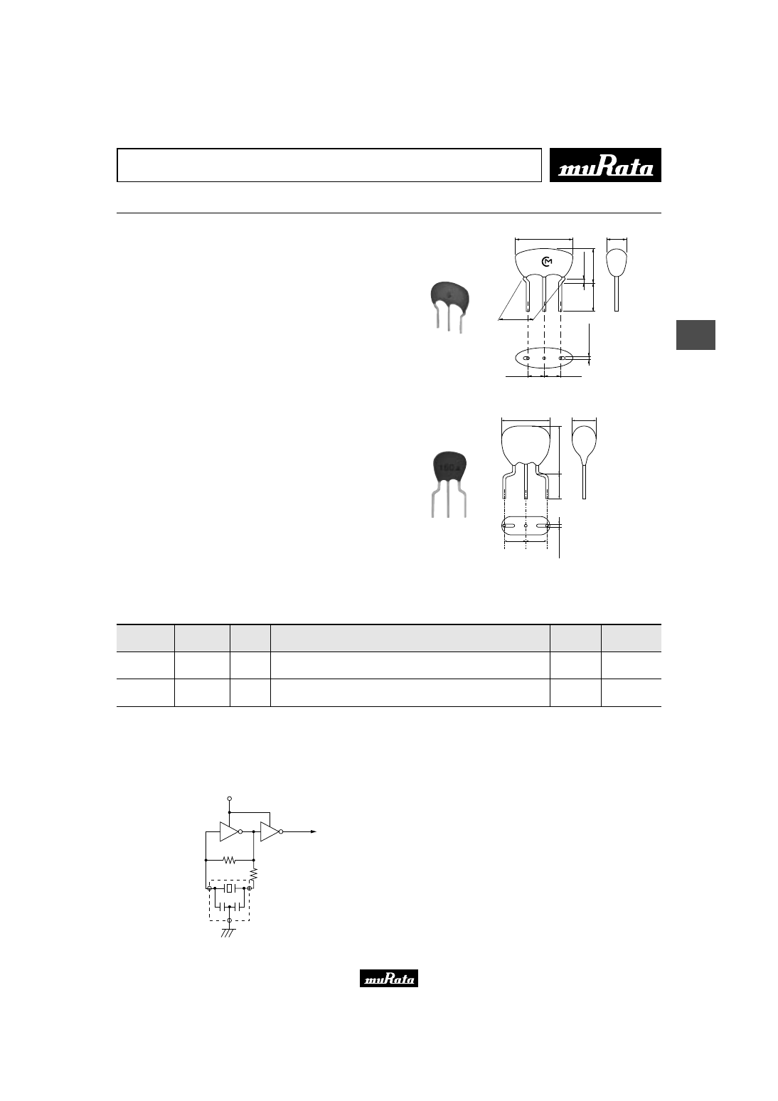
■ Oscillation Frequency Temperature Stability
CSTLS_G
O
s
c
ill
a
ti
n
g
F
re
q
u
e
n
c
y
S
h
if
t
(%
)
Temperature (
°
C)
Y
40
W
0.50
W
0.25
0
Y
0.25
Y
0.50
0
40
80
120
CSTLS_X
Temperature (˚C)
O
s
c
ill
a
ti
n
g
F
re
q
u
e
n
c
y
S
h
if
t
(%
)
0.3
0.2
0.1
0.0
−
0.1
−
0.2
−
0.3
−
50
−
30
−
10
10
30
50
70
90
110
130
Please read rating and
!
CAUTION (for storage, operating, rating, soldering, mounting and handling) in this PDF catalog to prevent smoking and/or burning, etc.
This catalog has only typical specifications. Therefore, you are requested to approve our product specifications or to transact the approval sheet for product specifications before ordering.
!
Note
P16E15.pdf 04.8.27
17
4
!
Note
• Please read rating and
!
CAUTION (for storage, operating, rating, soldering, mounting and handling) in this catalog to prevent smoking and/or burning, etc.
• This catalog has only typical specifications because there is no space for detailed specifications. Therefore, please approve our product specifications or transact the approval sheet for product specifications before ordering.
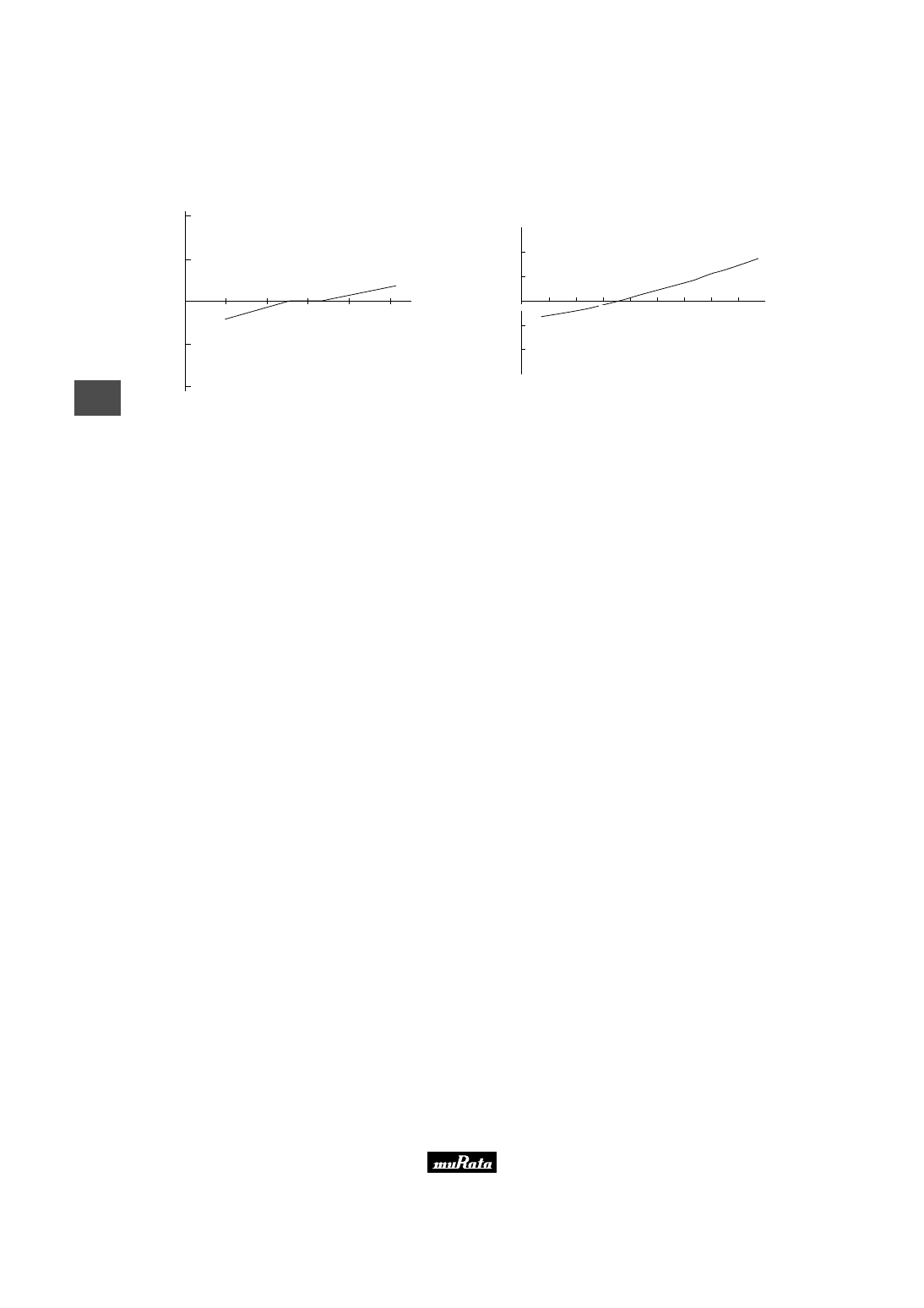
Ceramic Resonators (CERALOCKr)
Lead Type Two Terminals CSALS Series
"CERALOCK" with two leaded terminals.
The CSALS series ceramic resonators owe their
development to MURATA's innovative expert technologies
and the application of mass production techniques
typically utilized in the manufacture of piezoelectric
ceramic components. Because of their high mechanical Q
and consistent high quality, CSALS series are ideally
suited to microprocessor and remote control unit
applications.
In addition, MURATA offers a special "CERALOCK"
version suitable for automatic insertion utilizing
tape and reel and other packaging forms. For further
information, please contact your local MURATA
representative office or authorized distributor.
■ Features
1. The series is stable over a wide temperature range
and with respect to long-term aging.
2. The series comprises fixed, tuned, solid-state
devices.
3. The resonators are miniature and light weight.
4. They exhibit excellent shock resistance
performance.
5. Oscillating circuits requiring no adjustment can
be designed by utilizing these resonators in
conjunction with transistors or appropriate ICs.
■ Applications
1. Square-wave and sine-wave oscillator
2. Clock generator for microprocessors
3. Remote control systems
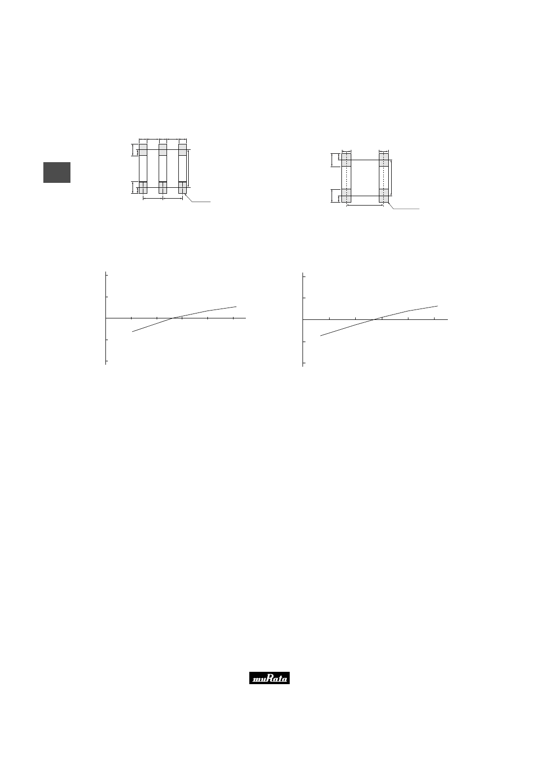
∗
5.5
±
1.0
T
∗
1
T
: 3.5
±
1.0 (16.00—32.99MHz)
3.0
±
1.0 (33.00—70.00MHz)
∗
1
5.0
±
0.3
6
.5
±
0
.5
3
.5
±
0
.3
φ
0
.4
8
±
0
.0
5
(in mm)
∗
: EIAJ Monthly Code
CSALS_X
16.00-70.00MHz
Part Number
Oscillating
Frequency
(MHz)
Initial
Tolerance
(%)
Temp. Stability
(%)
Temperature
Range
(
°
C)
Use
CSALS_X
16.00 to 70.00
±
0.5
±
0.2
-20 to +80
For consumer
electronics
Irregular or stop oscillation may occur under unmatched circuit conditions. Please check the actual conditions prior to use.
The order quantity should be an integral multiple of the "Minimum Quantity" shown in the packaging page.
Please read rating and
!
CAUTION (for storage, operating, rating, soldering, mounting and handling) in this PDF catalog to prevent smoking and/or burning, etc.
This catalog has only typical specifications. Therefore, you are requested to approve our product specifications or to transact the approval sheet for product specifications before ordering.
!
Note
P16E15.pdf 04.8.27
18
4
!
Note
• Please read rating and
!
CAUTION (for storage, operating, rating, soldering, mounting and handling) in this catalog to prevent smoking and/or burning, etc.
• This catalog has only typical specifications because there is no space for detailed specifications. Therefore, please approve our product specifications or transact the approval sheet for product specifications before ordering.
■ Oscillation Frequency Measuring Circuit
Rf
Rd
VDD
CL2
CL1
To Frequency counter
■ Oscillation Frequency Temperature Stability
CSALS_X
Temperature (˚C)
O
s
c
ill
a
ti
n
g
F
re
q
u
e
n
c
y
S
h
if
t
(%
)
0.3
0.2
0.1
0.0
−
0.1
−
0.2
−
0.3
−
50
−
30
−
10
10
30
50
70
90
110
130
Please read rating and
!
CAUTION (for storage, operating, rating, soldering, mounting and handling) in this PDF catalog to prevent smoking and/or burning, etc.
This catalog has only typical specifications. Therefore, you are requested to approve our product specifications or to transact the approval sheet for product specifications before ordering.
!
Note
P16E15.pdf 04.8.27

MHz Lead Type Notice
19
4
!
Note
• Please read rating and
!
CAUTION (for storage, operating, rating, soldering, mounting and handling) in this catalog to prevent smoking and/or burning, etc.
• This catalog has only typical specifications because there is no space for detailed specifications. Therefore, please approve our product specifications or transact the approval sheet for product specifications before ordering.
■ Notice (Soldering and Mounting)
The component cannot withstand washing.
■ Notice (Storage and Operating Conditions)
Please do not apply excess mechanical stress to the
component and lead terminals during soldering.
Conformal coating or washing of the component is not
acceptable because it is not hermetically sealed.
■ Notice (Rating)
The component may be damaged if excess mechanical
stress is applied.
■ Notice (Handling)
"CERALOCK" may stop oscillating or oscillate
irregularly under improper circuit conditions.
Please read rating and
!
CAUTION (for storage, operating, rating, soldering, mounting and handling) in this PDF catalog to prevent smoking and/or burning, etc.
This catalog has only typical specifications. Therefore, you are requested to approve our product specifications or to transact the approval sheet for product specifications before ordering.
!
Note
P16E15.pdf 04.8.27
MHz Lead Type CSTLS Series Packaging
20
4
!
Note
• Please read rating and
!
CAUTION (for storage, operating, rating, soldering, mounting and handling) in this catalog to prevent smoking and/or burning, etc.
• This catalog has only typical specifications because there is no space for detailed specifications. Therefore, please approve our product specifications or transact the approval sheet for product specifications before ordering.
■ Minimum Quantity
Part Number
Ammo Pack
(pcs.)
The order quantity should be an integral multiple of the "Minimum Quantity" shown above.
Bulk
500
500
CSTLS_G (3.40 to 10.0MHz)
2,000
CSTLS_X (16.00 to 70.00MHz)
2,000
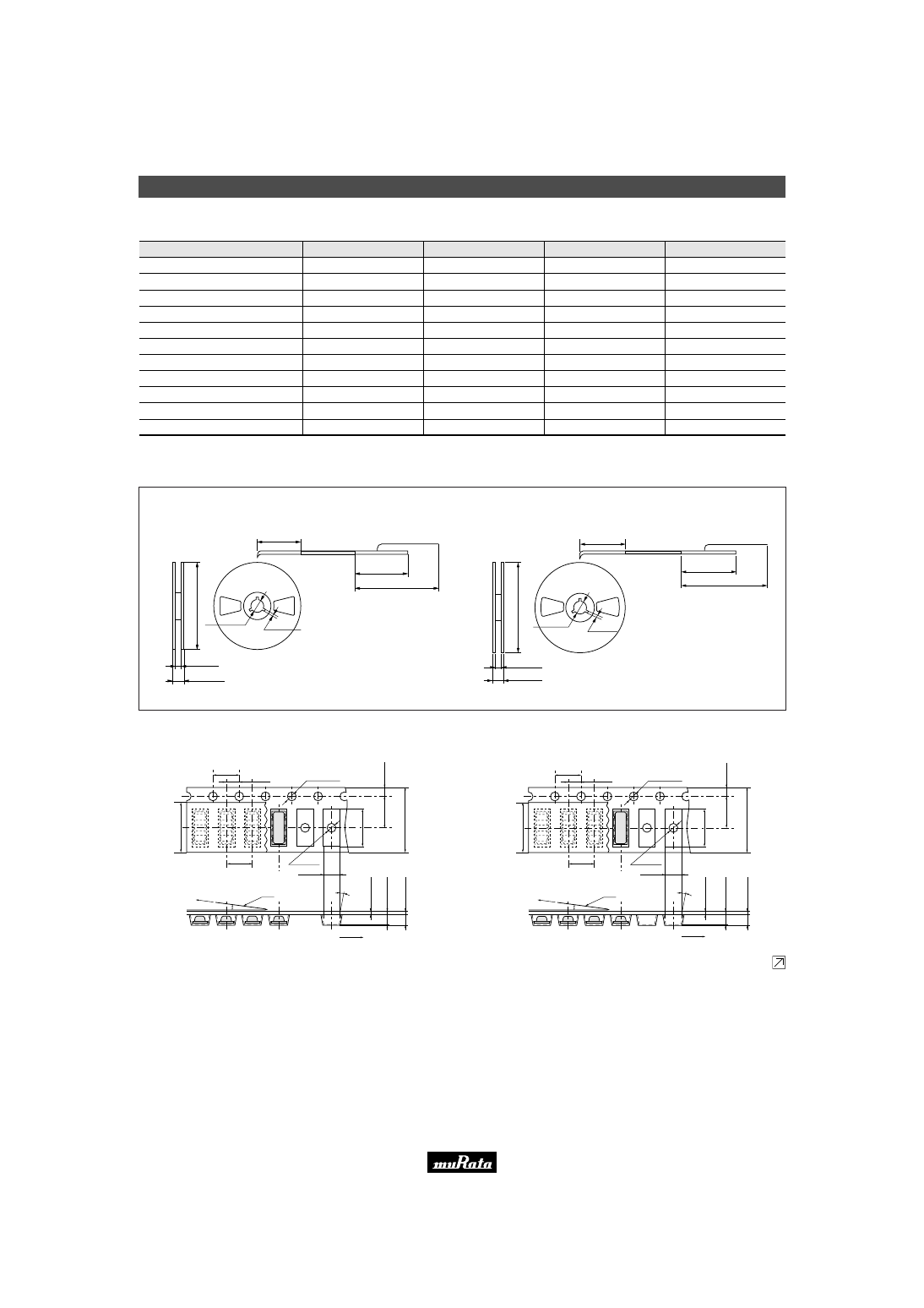
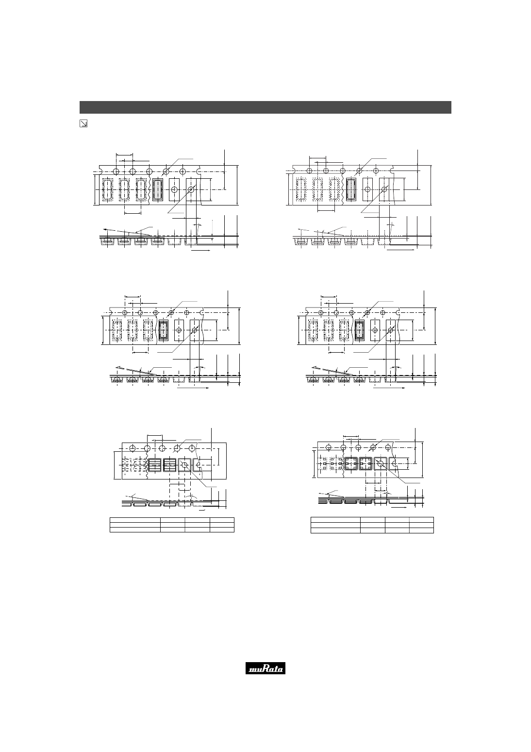
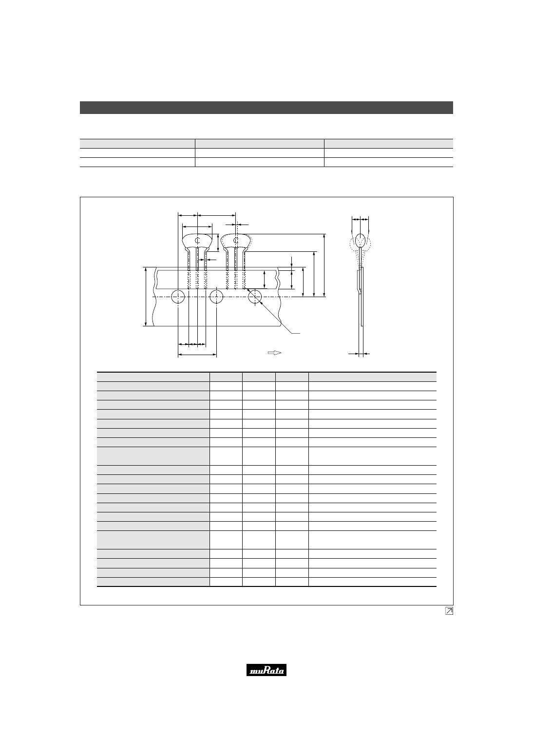
■ Tape Dimensions of CSTLS_G
(in mm)
Width of diameter
Height of resonator
Dimensions of terminal
Lead length under the hold down tape
Pitch of component
Pitch of sprocket hole
Length from sprocket hole center to lead
Length from sprocket hole center to
component center
Lead spacing (I)
Lead spacing (II)
Slant forward or backward
Width of carrier tape
Width of hold down tape
Position of sprocket hole
Gap of hold down tape and carrier tape
Distance between the center of
sprocket hole and lead stopper
Total height of resonator
Diameter of sprocket hole
Total tape thickness
Body tilt
Item
Code
Dimensions
Tolerance
Remarks
D
A
d
L
1
P
P
0
P
1
P
2
F
1
F
2
dh
W
W
0
W
1
W
2
H
0
H
1
D
0
t
dS
8.0
5.5
ø0.48
5.0 min.
12.7
12.7
3.85
6.35
2.5
2.5
0
18.0
6.0 min.
9.0
0
18.0
23.5
ø4.0
0.6
0
±
1.0
±
0.5
±
0.05
–
±
0.5
±
0.2
±
0.5
±
0.5
±
0.2
±
0.2
±
1.0
±
0.5
–
±
0.5
±
0.5
±
1.0
±
0.2
±
0.2
±
1.0
Tolerance for Pitches 10xP
0
=127
±
1
1mm max.
Hold down tape does not exceed the carrier tape.
W
0.5
Y
0
M
∗
M
∗
∗
∗
∗
∗
P
2
D
A
P
dS
W
H
0
H
1
W
1
W
0
L
1
W
2
D
0
t
P
0
P
1
F
1
F
2
Direction of Feed
dh dh
d
Continued on the following page.
Please read rating and
!
CAUTION (for storage, operating, rating, soldering, mounting and handling) in this PDF catalog to prevent smoking and/or burning, etc.
This catalog has only typical specifications. Therefore, you are requested to approve our product specifications or to transact the approval sheet for product specifications before ordering.
!
Note
P16E15.pdf 04.8.27
MHz Lead Type CSTLS Series Packaging
21
4
!
Note
• Please read rating and
!
CAUTION (for storage, operating, rating, soldering, mounting and handling) in this catalog to prevent smoking and/or burning, etc.
• This catalog has only typical specifications because there is no space for detailed specifications. Therefore, please approve our product specifications or transact the approval sheet for product specifications before ordering.
Continued from the preceding page.
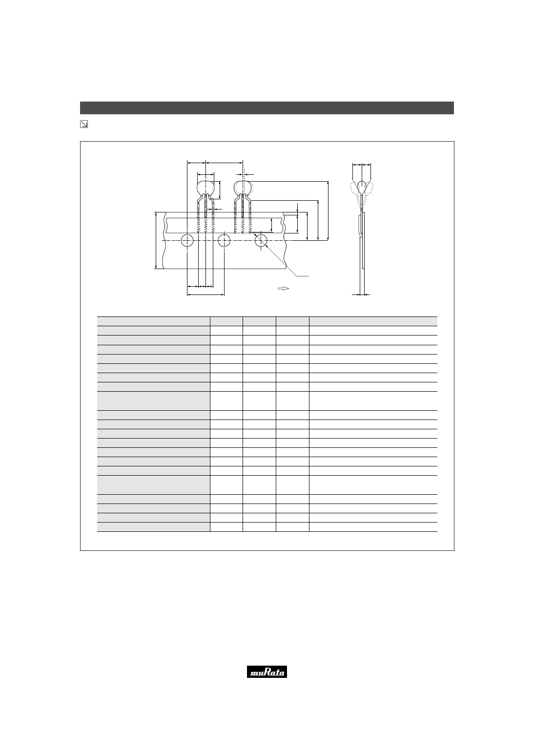
■ Tape Dimensions of CSTLS_X
(in mm)
Width of diameter
Height of resonator
Dimensions of terminal
Lead length under the hold down tape
Pitch of component
Pitch of sprocket hole
Length from sprocket hole center to lead
Length from sprocket hole center to
component center
Lead spacing (I)
Lead spacing (II)
Slant forward or backward
Width of carrier tape
Width of hold down tape
Position of sprocket hole
Gap of hold down tape and carrier tape
Distance between the center of
sprocket hole and lead stopper
Total height of resonator
Diameter of sprocket hole
Total tape thickness
Body tilt
Item
Code
Dimensions
Tolerance
Remarks
D
A
d
L
1
P
P
0
P
1
P
2
F
1
F
2
dh
W
W
0
W
1
W
2
H
0
H
1
D
0
t
dS
5.5
6.5
ø0.48
5.0 min.
12.7
12.7
3.85
6.35
2.5
2.5
0
18.0
6.0 min.
9.0
0
18.0
24.5
ø4.0
0.6
0
±
1.0
±
0.5
±
0.05
–
±
0.5
±
0.2
±
0.5
±
0.5
±
0.2
±
0.2
±
1.0
±
0.5
–
±
0.5
±
0.5
±
0.1
±
0.2
±
0.2
±
1.0
Tolerance for Pitches 10xP
0
=127
±
1
1mm max.
Hold down tape doesn't exceed the carrier tape.
W
0.5
Y
0.0
D
dS
d
P
2
P
A
W
0
L
1
W
1
W
2
H
0
H
1
P
1
P
0
t
F
1
F
2
W
D
0
dh dh
Direction of Feed
Please read rating and
!
CAUTION (for storage, operating, rating, soldering, mounting and handling) in this PDF catalog to prevent smoking and/or burning, etc.
This catalog has only typical specifications. Therefore, you are requested to approve our product specifications or to transact the approval sheet for product specifications before ordering.
!
Note
P16E15.pdf 04.8.27
MHz Lead Type CSALS Series Packaging
22
4
!
Note
• Please read rating and
!
CAUTION (for storage, operating, rating, soldering, mounting and handling) in this catalog to prevent smoking and/or burning, etc.
• This catalog has only typical specifications because there is no space for detailed specifications. Therefore, please approve our product specifications or transact the approval sheet for product specifications before ordering.
■ Minimum Quantity
CSALS_X (16.00 to 70.00MHz)
Part Number
Ammo Pack
2,000
Bulk
500
(pcs.)
The order quantity should be an integral multiple of the "Minimum Quantity" shown above.
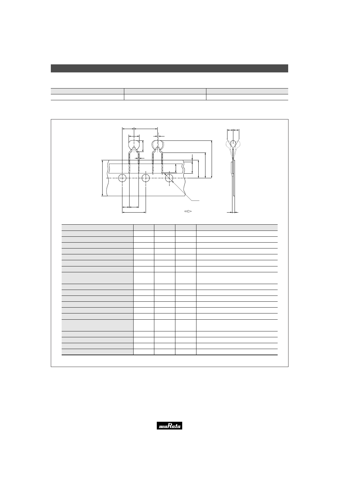
■ Tape Dimensions of CSALS
(in mm)
Width of diameter
Height of resonator
Dimensions of terminal
Lead length under the hold down tape
Pitch of component
Pitch of sprocket hole
Length from sprocket hole center to lead
Length from sprocket hole center to
component center
Lead spacing
Slant forward or backward
Width of carrier tape
Width of hold down tape
Position of sprocket hole
Gap of hold down tape and carrier tape
Distance between the center of
sprocket hole and lead stopper
Total height of resonator
Diameter of sprocket hole
Total tape thickness
Body tilt
Item
Code
Dimensions
Tolerance
Remarks
D
A
d
L
1
P
P
0
P
1
P
2
F
dh
W
W
0
W
1
W
2
H
0
H
1
D
0
t
dS
5.5
6.5
ø0.48
5.0 min.
12.7
12.7
3.85
6.35
5.0
0
18.0
6.0 min.
9.0
0
18.0
24.5
ø4.0
0.6
0
±
1.0
±
0.5
±
0.05
———
±
0.5
±
0.2
±
0.5
±
0.5
±
0.3
±
1.0
±
0.5
———
±
0.5
±
0.5
±
1.0
±
0.2
±
0.2
±
1.0
Tolerance for Pitches 10xP
0
=127
±
1
1mm max.
Hold down tape doesn't exceed the carrier tape.
+0.5
- 0
D
dS
d
P
2
P
A
W
0
L
1
W
1
W
2
H
0
H
1
P
1
P
0
t
F
W
D
0
dh dh
Direction of Feed
Please read rating and
!
CAUTION (for storage, operating, rating, soldering, mounting and handling) in this PDF catalog to prevent smoking and/or burning, etc.
This catalog has only typical specifications. Therefore, you are requested to approve our product specifications or to transact the approval sheet for product specifications before ordering.
!
Note
P16E15.pdf 04.8.27
23
5
!
Note
• Please read rating and
!
CAUTION (for storage, operating, rating, soldering, mounting and handling) in this catalog to prevent smoking and/or burning, etc.
• This catalog has only typical specifications because there is no space for detailed specifications. Therefore, please approve our product specifications or transact the approval sheet for product specifications before ordering.
Ceramic Resonators (CERALOCKr)
Chip Type Two Terminals CSBFB Series
Can be reflow soldered and mounted by automatic
placers. MURATA's original package technologies have
enabled the development of the kHz band "CERALOCK".
The series is perfect in miniature remote control
units and AV modules.
■ Features
1. The series withstands reflow soldering.
2. The series is mountable by automatic placers.
3. No adjustment is necessary for oscillation circuits.
■ Applications
1. Clock oscillators for microprocessors
2. OA equipment
3. AV modules
7.5
±
0.3
1.1
±
0.1
0.9
±
0.1
3.3
±
0.3
0.15
±
0.05
1
.0
m
a
x
.
0
.1
5
m
a
x
.
2
.0
±
0
.5
8
.5
±
0
.3
1
.0
±
0
.5
5.0
±
0.2
0
+0.1
-0.4
∗
: EIAJ code
(in mm)
CSBFB_J
430-519kHz
5.0
±
0.3
0.8
±
0.2
0.7
±
0.2
2.5
±
0.2
2.3
±
0.2
0.15
±
0.05
0.10
±
0.03
1
.0
m
a
x
.
6
.0
±
0
.3
2
.0
±
0
.5
1
.0
±
0
.3
0
.1
5
m
a
x
.
0
+
0.1
−
0.4
∗
: EIAJ code
(in mm)
CSBFB_J
700-1250kHz
Part Number
Oscillating Frequency
(kHz)
Initial Tolerance
Temp. Stability
(%)
Temperature Range
(
°
C)
CSBFB_J
430 to 519, 700 to 1250
±
0.5%
±
0.3
-20 to +80
Irregular or stop oscillation may occur under unmatched circuit conditions. Please check the actual conditions prior to use.
■ Oscillation Frequency Measuring Circuit
Rf
Rd
VDD
CL2
CL1
To Frequency counter
■ Oscillation Frequency Temperature Stability
Y
40
80
40
120
W
0.5
0
Y
0.5
Temperature (˚C)
0
O
s
c
ill
a
ti
n
g
F
re
q
u
e
n
c
y
S
h
if
t
(%
)
Continued on the following page.
Please read rating and
!
CAUTION (for storage, operating, rating, soldering, mounting and handling) in this PDF catalog to prevent smoking and/or burning, etc.
This catalog has only typical specifications. Therefore, you are requested to approve our product specifications or to transact the approval sheet for product specifications before ordering.
!
Note
P16E15.pdf 04.8.27
24
5
!
Note
• Please read rating and
!
CAUTION (for storage, operating, rating, soldering, mounting and handling) in this catalog to prevent smoking and/or burning, etc.
• This catalog has only typical specifications because there is no space for detailed specifications. Therefore, please approve our product specifications or transact the approval sheet for product specifications before ordering.
Continued from the preceding page.
■ Standard Land Pattern Dimensions
CSBFB_J (430-519kHz)
3.3
1.7
1.7
2
.0
0
.5
(in mm)
CSBFB_J (700-1250kHz)
1.0
1.5
1.5
3
.0
0
.5
(in mm)
Please read rating and
!
CAUTION (for storage, operating, rating, soldering, mounting and handling) in this PDF catalog to prevent smoking and/or burning, etc.
This catalog has only typical specifications. Therefore, you are requested to approve our product specifications or to transact the approval sheet for product specifications before ordering.
!
Note
P16E15.pdf 04.8.27
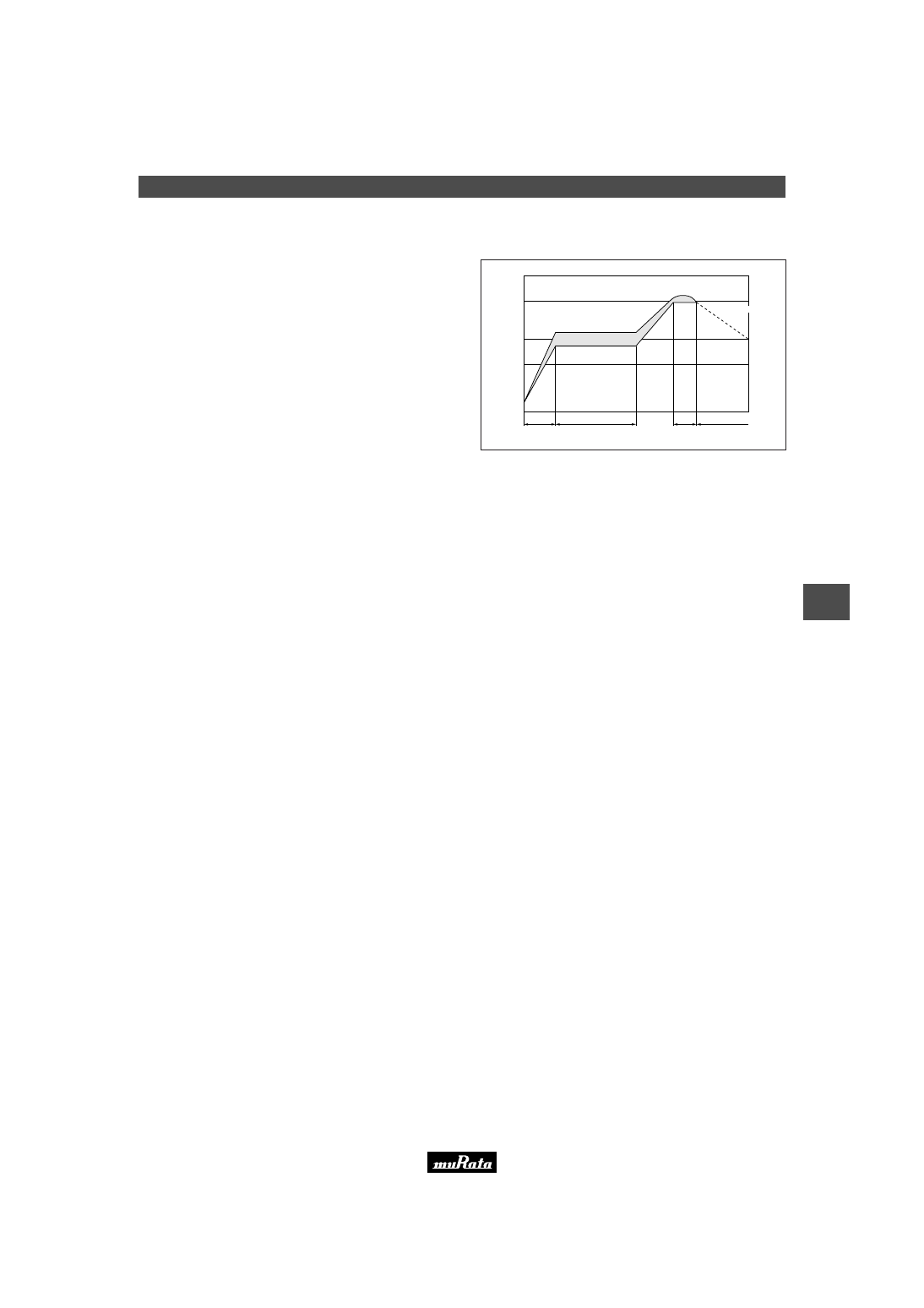
One heat stress, shown in the profile at right, is applied to
resonator; then, after being placed in natural conditions
for 1 hour, the resonator is measured.
1. Pre-heating conditions should be +140 to +160
°
C for
60 to 120 seconds. Ascending time up to +150
°
C
should be longer than 30 seconds.
2. Heating conditions should be within 20 seconds at
+225
°
C min., but peak temperature should be Iower
than +235
°
C.
1. Soldering Conditions
(1) Reflow
HCFC, Isopropanol, Tap water, Demineralized water,
Cleanthrough750H, Pine alpha 100S, Techno care FRW
2. Wash
(1) Cleaning Solvents
dT<=60
°
C (dT=Component-solvent)
*1 ex. In case the component at +90
°
C immerses into
cleaning solvent at +60
°
C, then dT=30
°
C.
(2) Temperature Difference : dT *1
5 minutes max. by air blow at +80
°
C max.
(4) Drying
1. Total washing time should be within 10 minutes.
2. Please insure the component is thoroughly evaluated
in your application circuit.
3. The component may be damaged if it is washed with
chlorine, petroleum, or alkali cleaning solvent.
(5) Others
1. Ultrasonic Wash
1 minute max. in above solvent at +60
°
C max.
(Frequency : 28kHz, Output : 20W/L)
2. Immersion Wash
5 minutes max. in above solvent at +60
°
C max.
3. Shower or Rinse Wash
5 minutes max. in above solvent at +60
°
C max.
(3) Conditions
Soldering iron of +270
±
5
°
C should be placed 0.5mm
above electrode of resonator. Melting solder through
soldering iron should be applied to electrode for 3
±
1
seconds; then, after being placed in natural conditions for
24 hours, the resonator should be measured.
(2) Soldering Iron
T
e
m
p
e
ra
tu
re
(
°
C
)
225
Pre-heating
(in air)
Soldering Peak Temperature 235
°
C max.
30 sec. min.
60 to 120 sec.
20 sec. max. 120 sec. min.
150
100
Gradual Cooling
(in air)
kHz Chip Type CSBFB_J 430-519kHz Notice (Soldering and Mounting)
25
5
!
Note
• Please read rating and
!
CAUTION (for storage, operating, rating, soldering, mounting and handling) in this catalog to prevent smoking and/or burning, etc.
• This catalog has only typical specifications because there is no space for detailed specifications. Therefore, please approve our product specifications or transact the approval sheet for product specifications before ordering.
Please read rating and
!
CAUTION (for storage, operating, rating, soldering, mounting and handling) in this PDF catalog to prevent smoking and/or burning, etc.
This catalog has only typical specifications. Therefore, you are requested to approve our product specifications or to transact the approval sheet for product specifications before ordering.
!
Note
P16E15.pdf 04.8.27
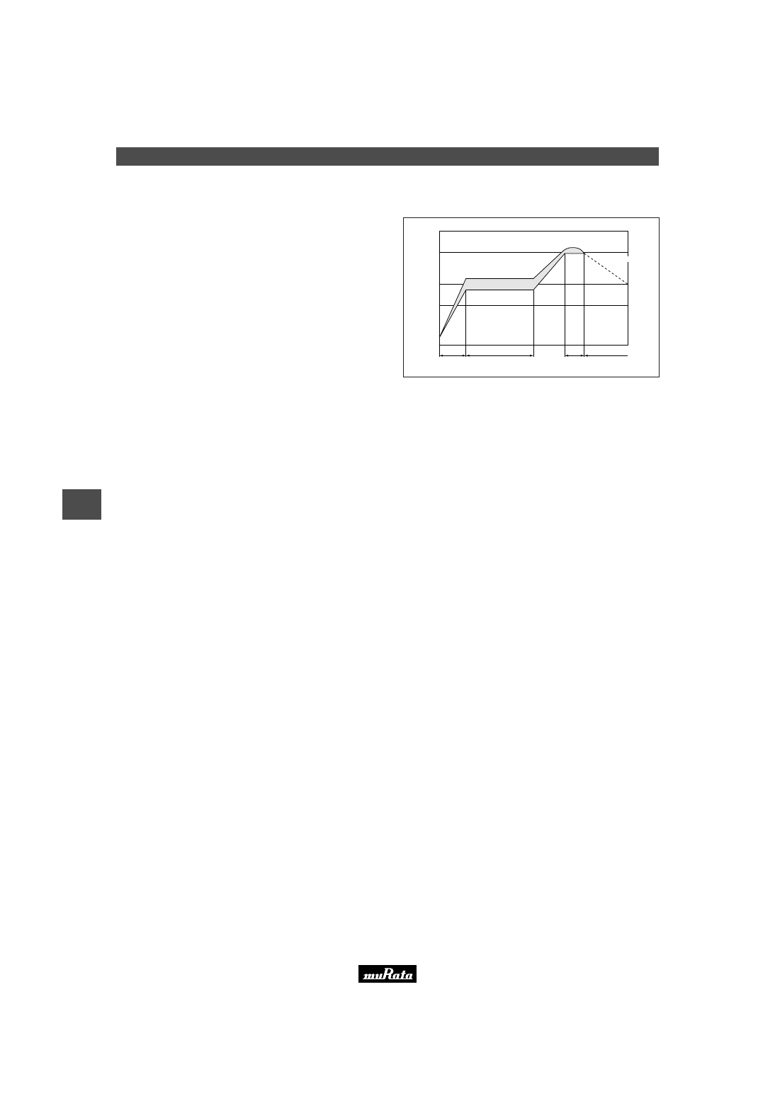
One heat stress, shown in the profile at right, is applied to
resonator; then, after being placed in natural conditions
for 1 hour, the resonator is measured.
1. Pre-heating conditions should be +140 to +160
°
C for
60 to 120 seconds. Ascending time up to +150
°
C
should be longer than 30 seconds.
2. Heating conditions should be within 20 seconds at
+215
°
C min., but peak temperature should be Iower
than +225
°
C.
1. Soldering Condition
(1) Reflow
HCFC, Isopropanol, Tap water, Demineralized water,
Cleanthrough750H, Pine alpha 100S, Techno care FRW
2. Wash
(1) Cleaning Solvents
dT<=60
°
C (dT=Component-solvent)
*1 ex. In case the component at +90
°
C immerses into
cleaning solvent at +60
°
C, then dT=30
°
C.
(2) Temperature Difference : dT *1
5 minutes max. by air blow at +80
°
C max.
(4) Drying
1. Total washing time should be within 10 minutes.
2. Please insure the component is thoroughly evaluated
in your application circuit.
3. The component may be damaged if it is washed with
chlorine, petroleum, or alkali cleaning solvent.
(5) Others
1. Ultrasonic Wash
1 minute max. in above solvent at +60
°
C max.
(Frequency : 28kHz, Output : 20W/L)
2. Immersion Wash
5 minutes max. in above solvent at +60
°
C max.
3. Shower or Rinse Wash
5 minutes max. in above solvent at +60
°
C max.
(3) Conditions
Soldering iron of +270
±
5
°
C should be placed 0.5mm
above electrode of resonator. Melting solder through
soldering iron should be applied to electrode for 3
±
1
seconds; then, after being placed in natural conditions for
24 hours, the resonator should be measured.
(2) Soldering Iron
T
e
m
p
e
ra
tu
re
(
°
C
)
215
Pre-heating
(in air)
Soldering Peak Temperature 225
°
C max.
30 sec. min.
60 to 120 sec.
20 sec. max. 120 sec. min.
150
100
Gradual Cooling
(in air)
kHz Chip Type CSBFB_J 700-1250kHz Notice (Soldering and Mounting)
26
5
!
Note
• Please read rating and
!
CAUTION (for storage, operating, rating, soldering, mounting and handling) in this catalog to prevent smoking and/or burning, etc.
• This catalog has only typical specifications because there is no space for detailed specifications. Therefore, please approve our product specifications or transact the approval sheet for product specifications before ordering.
Please read rating and
!
CAUTION (for storage, operating, rating, soldering, mounting and handling) in this PDF catalog to prevent smoking and/or burning, etc.
This catalog has only typical specifications. Therefore, you are requested to approve our product specifications or to transact the approval sheet for product specifications before ordering.
!
Note
P16E15.pdf 04.8.27
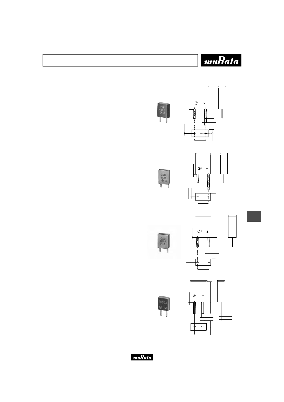
27
6
!
Note
• Please read rating and
!
CAUTION (for storage, operating, rating, soldering, mounting and handling) in this catalog to prevent smoking and/or burning, etc.
• This catalog has only typical specifications because there is no space for detailed specifications. Therefore, please approve our product specifications or transact the approval sheet for product specifications before ordering.
Ceramic Resonators (CERALOCKr)
Lead Type Two Terminals CSBLA Series
"CERALOCK" with two leaded terminals.
The CSBLA series ceramic resonators owe their
development to MURATA's innovative expert technologies
and the application of mass production techniques
typically utilized in the manufacture of piezoelectric
ceramic components. Because of their high mechanical Q
and consistent high quality, the CSBLA series are
ideally suited to microprocessor and remote control
unit applications.
■ Features
1. The series is stable over a wide temperature range
and with respect to long-term aging.
2. The series comprises fixed, tuned, solid-state
devices.
3. The resonators are miniature and light weight.
4. They exhibit excellent shock resistance performance.
5. Oscillating circuits requiring no adjustment can be
designed by utilizing these resonators in
conjunction with transistors or appropriate ICs.
■ Applications
1. Square-wave and sine-wave oscillators
2. Clock generator for microprocessors
3. Remote control systems
7.9
±
0.3
3.6
±
0.3
0.8
±
0.1
1.1
±
0.1
5.0
±
0.2
1
.8
±
0
.2
5
0
.1
±
0
.0
3
0
.2
5
±
0
.1
4
.3
±
0
.5
9
.3
±
0
.3
1
.5
m
a
x
.
∗
: EIAJ code
(in mm)
CSBLA_E
375-429kHz
7.0
±
0.3
3.5
±
0.3
0.8
±
0.1
1.1
±
0.1
5.0
±
0.2
1
.7
5
±
0
.5
3
.5
±
0
.5
9
.0
±
0
.3
0
.1
±
0
.0
3
0
.2
5
±
0
.1
1
.5
m
a
x
.
∗
: EIAJ code
(in mm)
CSBLA_E
430-509kHz
7.0
±
0.3
3.5
±
0.3
0.8
±
0.1
1.1
±
0.1
5.0
±
0.2
1
.7
5
±
0
.5
3
.5
±
0
.5
9
.0
±
0
.3
0
.1
±
0
.0
3
0
.2
5
±
0
.1
1
.5
m
a
x
.
∗
: EIAJ code
(in mm)
CSBLA_E
510-699kHz
1
.5
m
a
x
.
5.0
±
0.3
2.2
±
0.2
6
.0
±
0
.3
3
.5
±
.0
.5
0.8
±
0.2
2.5
±
0.2
1
.1
±
0
.2
0.6
±
0.2
0.15
±
0.05
0.1
±
0.03
∗
: EIAJ code
in mm
CSBLA_J
700-1250kHz
Please read rating and
!
CAUTION (for storage, operating, rating, soldering, mounting and handling) in this PDF catalog to prevent smoking and/or burning, etc.
This catalog has only typical specifications. Therefore, you are requested to approve our product specifications or to transact the approval sheet for product specifications before ordering.
!
Note
P16E15.pdf 04.8.27
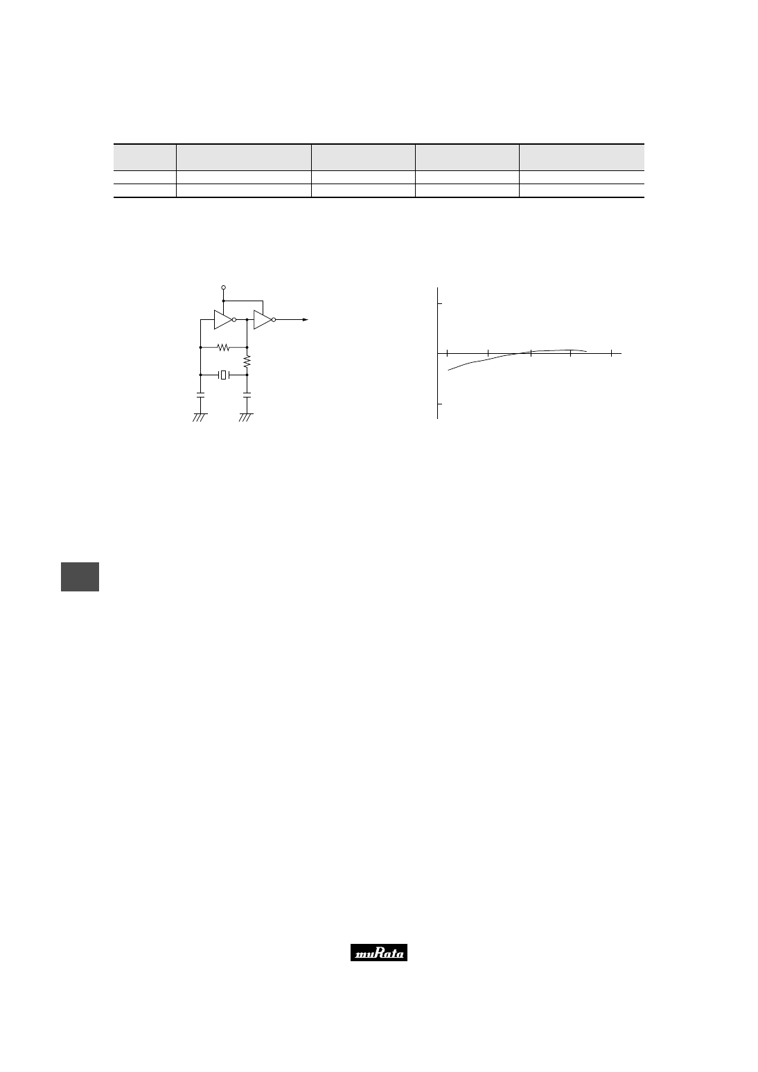
28
6
!
Note
• Please read rating and
!
CAUTION (for storage, operating, rating, soldering, mounting and handling) in this catalog to prevent smoking and/or burning, etc.
• This catalog has only typical specifications because there is no space for detailed specifications. Therefore, please approve our product specifications or transact the approval sheet for product specifications before ordering.
Part Number
Oscillating Frequency
(kHz)
Initial Tolerance
Temp. Stability
(%)
Temperature Range
(
°
C)
CSBLA_E
375 to 699
±
2kHz
±
0.3
-20 to +80
CSBLA_J
700 to 1250
±
0.5%
±
0.3
-20 to +80
Irregular or stop oscillation may occur under unmatched circuit conditions. Please check the actual conditions prior to use.
The order quantity should be an integral multiple of the "Minimum Quantity" shown in the packaging page.
■ Oscillation Frequency Measuring Circuit
Rf
Rd
VDD
CL2
CL1
To Frequency counter
■ Oscillation Frequency Temperature Stability
Y
40
80
40
120
W
0.5
0
Y
0.5
Temperature (˚C)
0
O
s
c
ill
a
ti
n
g
F
re
q
u
e
n
c
y
S
h
if
t
(%
)
Please read rating and
!
CAUTION (for storage, operating, rating, soldering, mounting and handling) in this PDF catalog to prevent smoking and/or burning, etc.
This catalog has only typical specifications. Therefore, you are requested to approve our product specifications or to transact the approval sheet for product specifications before ordering.
!
Note
P16E15.pdf 04.8.27

kHz Lead Type Notice
29
6
!
Note
• Please read rating and
!
CAUTION (for storage, operating, rating, soldering, mounting and handling) in this catalog to prevent smoking and/or burning, etc.
• This catalog has only typical specifications because there is no space for detailed specifications. Therefore, please approve our product specifications or transact the approval sheet for product specifications before ordering.
■ Notice (Soldering and Mounting)
CSBLA_E
The component cannot withstand washing.
■ Notice (Soldering and Mounting)
CSBLA_J
(1) Cleaning Solvents
HCFC, Isopropanol, Tap water, Demineralized water,
Cleanthrough750H, Pine alpha 100S, Techno care
FRW.
(2) Temperature Difference: dT *1
dT<=30 C. (dT=Component-solvent)
*1 ex. In case the component at +90 C. immerses
into cleaning solvent at +60 C., then
dT=30 C.
(3) Conditions
1. Ultrasonic Wash
1 minute max. in above solvent at +60 C. max.
(Frequency: 28kHz, Output: 20W/L)
2. Immersion Wash
5 minutes max. in above solvent at +60 C. max.
3. Shower or Rinse Wash
5 minutes max. in above solvent at +60 C. max.
(4) Drying
5 minutes max. by air blow at +80 C. max.
(5) Others
1. Total washing time should be within 10 minutes.
2. Please insure the component is thoroughly
evaluated in your application circuit.
3. The component may be damaged if it is washed
with alkali cleaning solvent.
Please read rating and
!
CAUTION (for storage, operating, rating, soldering, mounting and handling) in this PDF catalog to prevent smoking and/or burning, etc.
This catalog has only typical specifications. Therefore, you are requested to approve our product specifications or to transact the approval sheet for product specifications before ordering.
!
Note
P16E15.pdf 04.8.27

kHz Type Notice
30
6
!
Note
• Please read rating and
!
CAUTION (for storage, operating, rating, soldering, mounting and handling) in this catalog to prevent smoking and/or burning, etc.
• This catalog has only typical specifications because there is no space for detailed specifications. Therefore, please approve our product specifications or transact the approval sheet for product specifications before ordering.
■ Notice (Storage and Operating Condition)
CSBFB_J
Please do not apply excess mechanical stress to the
component and lead terminals during soldering.
Conformal coating of the component is acceptable.
However, the resin material, curing temperature, and
other process conditions should be evaluated to
confirm that stable electrical characteristics are
maintained.
Ultrasonic cleaning of the component is acceptable.
However, the size of bath, size and thickness of PBC
should be evaluated to confirm that stable electrical
characteristics are maintained.
In the case of the bulk component, dry heating
treatment (130 C. for 5 hours min.) is required before
reflow soldering. Then, the component should be
soldered within 48 hours after dry heating treatment.
■ Notice (Storage and Operating Condition)
CSBLA_E
Please do not apply excess mechanical stress to the
component and lead terminals during soldering.
Conformal coating or washing to the component is not
acceptable because it is not hermetically sealed.
■ Notice (Storage and Operating Condition)
CSBLA_J
Please do not apply excess mechanical stress to the
component and lead terminals during soldering.
Conformal coating of the component is acceptable.
However, the resin material, curing temperature, and
other process conditions should be evaluated to
confirm that stable electrical characteristics are
maintained.
Ultrasonic cleaning of the component is acceptable.
However, the size of bath, size and thickness of PBC
should be evaluated to confirm that stable electrical
characteristics are maintained.
■ Notice (Rating)
The component may be damaged if excess mechanical
stress is applied.
■ Notice (Handling)
"CERALOCK" may stop oscillating or oscillate
irregularly under improper circuit conditions.
Please read rating and
!
CAUTION (for storage, operating, rating, soldering, mounting and handling) in this PDF catalog to prevent smoking and/or burning, etc.
This catalog has only typical specifications. Therefore, you are requested to approve our product specifications or to transact the approval sheet for product specifications before ordering.
!
Note
P16E15.pdf 04.8.27
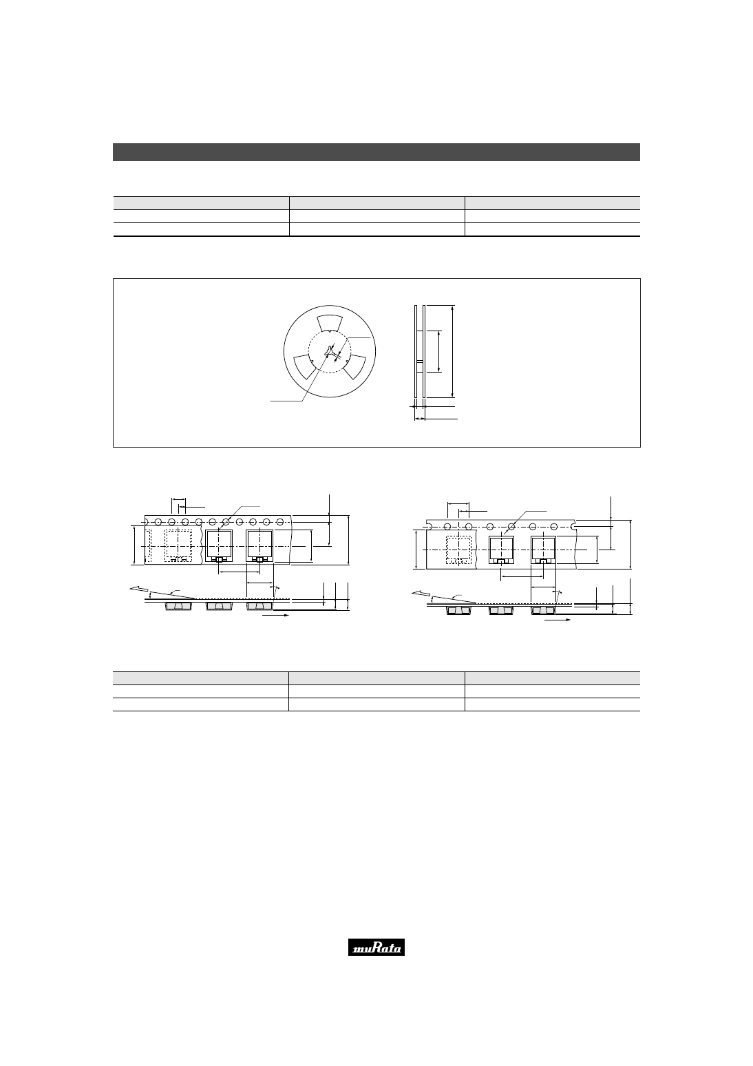
kHz Type Packaging
31
6
!
Note
• Please read rating and
!
CAUTION (for storage, operating, rating, soldering, mounting and handling) in this catalog to prevent smoking and/or burning, etc.
• This catalog has only typical specifications because there is no space for detailed specifications. Therefore, please approve our product specifications or transact the approval sheet for product specifications before ordering.
■ CSBFB Series Minimum Quantity
(in mm)
CSBFB_J (430 to 519kHz)
CSBFB_J (700 to 1250kHz)
Part Number
Bulk
Plastic Tape ø330mm
1,500
3,000
500
1,000
ø13.0
±
0.2
2.0
±
0.5
(ø
8
0
±
1
.0
)
(ø
3
3
0
)
17.5
±
0.5
21.5
±
1.0
(pcs.)
The order quantity should be an integral multiple of the "Minimum Quantity" shown above.
c Dimensions of Reel
■ Dimensions of Taping
CSBFB_J 430-519kHz
(in mm)
4.0
±
0.1
1
3
.3
±
0
.1
1
1
.4
±
0
.1
t0
.3
3
.5
±
0
.1
(4
.6
m
a
x
.)
7
.5
±
0
.1
1
6
.0
±
0
.3
1
.7
5
±
0
.1
2.0
±
0.1
12.0
±
0.1
8.05
±
0.1
Direction of Feed
Cover Film
3˚ max.
10˚
ø1.5
±
0.1
The cover film peel strength force 0.1 to 0.7N
The cover film peel speed 300mm/min.
CSBFB_J 700-1250kHz
(in mm)
4.0
±
0.1
1
3
.3
±
0
.1
8
.8
±
0
.1
t0
.3
2
.7
±
0
.1
(3
.0
7
m
a
x
.)
7
.5
±
0
.1
1
6
.0
±
0
.1
5
1
.7
5
±
0
.1
5
2.0
±
0.1
8.0
±
0.1
5.45
±
0.1
Direction of Feed
Cover Film
3˚ max.
10˚
ø1.5
±
0.1
The cover film peel strength force 0.1 to 0.7N
The cover film peel speed 300mm/min.
■ CSBLA Series Minimum Quantity
CSBLA_E
CSBLA_J
Part Number
Magazine
50
100
Bulk
500
1,000
(pcs.)
The order quantity should be an integral multiple of the "Minimum Quantity" shown above.
Please read rating and
!
CAUTION (for storage, operating, rating, soldering, mounting and handling) in this PDF catalog to prevent smoking and/or burning, etc.
This catalog has only typical specifications. Therefore, you are requested to approve our product specifications or to transact the approval sheet for product specifications before ordering.
!
Note
P16E15.pdf 04.8.27
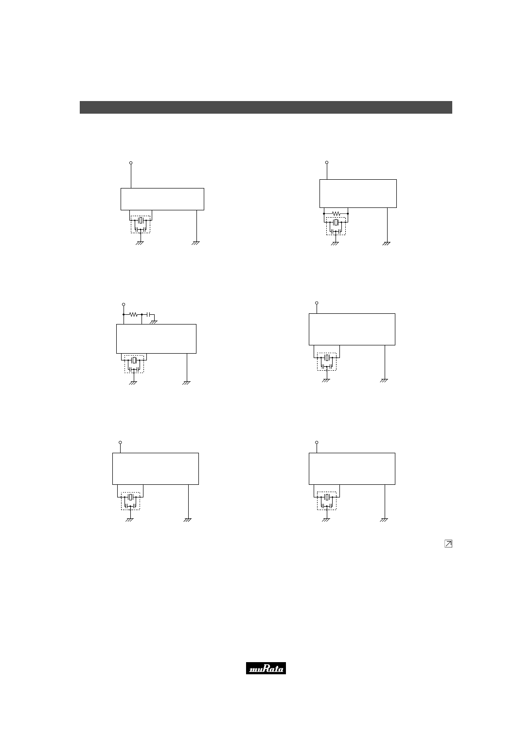
Utilizing Application Circuits
32
6
!
Note
• Please read rating and
!
CAUTION (for storage, operating, rating, soldering, mounting and handling) in this catalog to prevent smoking and/or burning, etc.
• This catalog has only typical specifications because there is no space for detailed specifications. Therefore, please approve our product specifications or transact the approval sheet for product specifications before ordering.
■ TMP87CM40AN (TOSHIBA)
8-bit Microcomputer
CSTLS8M00G53-B0
22,42
20
19
L
IC : TMP87C846N
V
DD
(+5V)
C
1
C
2
L : 17,18,21
C
1
=15pF
C
2
=15pF
■ MC68HC908JB8 (MOTOROLA)
8-bit Microcomputer
5
2
3
1
IC : MC68HC908JB8
V
DD
(+5V)
CSTCR6M00G55-R0
Rf
C
1
C
2
C
1
=39pF
C
2
=39pF
■ uPD78018F (NEC)
8-bit Microcomputer
H
43
50
49
L
IC :
µ
PD78018F
V
DD
(+5V)
100k
Ω
0.01
µ
F
H : 48,59,60,63,64
L : 1-8,17,32,51,
54-58,61,62
CSTLS8M00G53-B0
C
1
C
2
C
1
=15pF
C
2
=15pF
■ HD64F3337 (HITACHI)
8-bit Microcomputer
H
3
2
L
CSTLS8M00G56-B0
IC : HD64F3337
V
CC
(+5V)
H : 4,7,8,9,47,55
L : 1,12,38,56,73
C
1
C
2
C
1
=47pF
C
2
=47pF
■ ML66517 (OKI)
8-bit Microcomputer
H
37
36
L
CSTLS8M00G56-B0
IC : ML66517
V
DD
(+5V)
H : 9,65
L : 10,35,55,75,76
C
1
C
2
C
1
=47pF
C
2
=47pF
■ M38039MF (MITSUBISHI)
8-bit Microcomputer
1
30
31
3,26,32
CSTLS8M00G53-B0
IC : M38039MF
V
CC
(+5V)
C
1
C
2
C
1
=15pF
C
2
=15pF
Continued on the following page.
Please read rating and
!
CAUTION (for storage, operating, rating, soldering, mounting and handling) in this PDF catalog to prevent smoking and/or burning, etc.
This catalog has only typical specifications. Therefore, you are requested to approve our product specifications or to transact the approval sheet for product specifications before ordering.
!
Note
P16E15.pdf 04.8.27
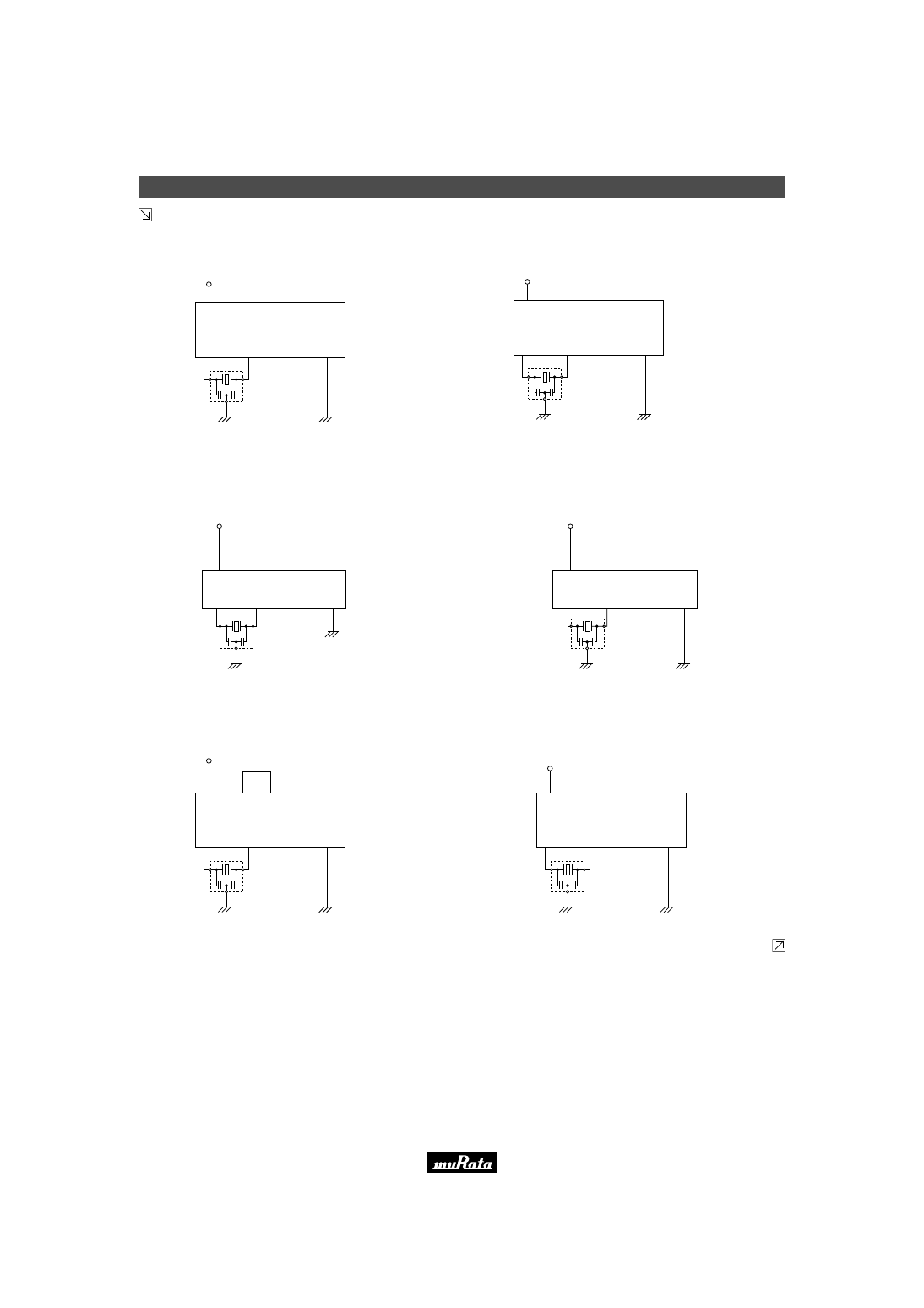
Utilizing Application Circuits
33
6
!
Note
• Please read rating and
!
CAUTION (for storage, operating, rating, soldering, mounting and handling) in this catalog to prevent smoking and/or burning, etc.
• This catalog has only typical specifications because there is no space for detailed specifications. Therefore, please approve our product specifications or transact the approval sheet for product specifications before ordering.
Continued from the preceding page.
■ M34280M1 (MITSUBISHI)
Remote Control Unit
20
4
5
1
CSTLS3M64G53-B0
IC : M34280M1
V
DD
(+3.0V)
C
1
=15pF
C
2
=15pF
C
1
C
2
■ uPD65 (NEC)
Speech Synthesizer
H
8
7
L
CERALOCK
®
: CSTLS3M64G53-B0
IC :
µ
PD65
V
DD
(+3V)
H : 6,10
L : 3,9,12,13,14
C
1
C
2
C
1
=15pF
C
2
=15pF
CERALOCK
®
■ uPD754304 (NEC)
4-bit Microcomputer
CSTLS4M00G53-B0
19,20
2
3
1,4
IC :
µ
PD754304
+5V
C
1
C
2
C
1
=15pF
C
2
=15pF
■ LC651154F (SANYO)
4-bit Microcomputer
CSTLS4M00G56-B0
10
L
IC : LC651154F
V
DD
(+5V)
C
1
8
C
2
9
C
1
=47pF
C
2
=47pF
L=1-7,16-20,25,26,29
■ LC7367JM (SANYO)
Tone/Pulse Dialer
H
9
10
L
CSTLS3M58GD6267-B0
IC : LC7367JM
V
DD
(+5V)
C
1
=47pF
C
2
=47pF
2
21
H=11
L=5,6,7,8,12
C
1
C
2
■ ML7005MB (OKI)
Tone/Pulse Dialer
9
11
12
23
CSTLS3M58GD3104-B0
IC : ML7005MB
V
DD
(+5.0V)
C
1
=15pF
C
2
=15pF
C
1
C
2
Continued on the following page.
Please read rating and
!
CAUTION (for storage, operating, rating, soldering, mounting and handling) in this PDF catalog to prevent smoking and/or burning, etc.
This catalog has only typical specifications. Therefore, you are requested to approve our product specifications or to transact the approval sheet for product specifications before ordering.
!
Note
P16E15.pdf 04.8.27
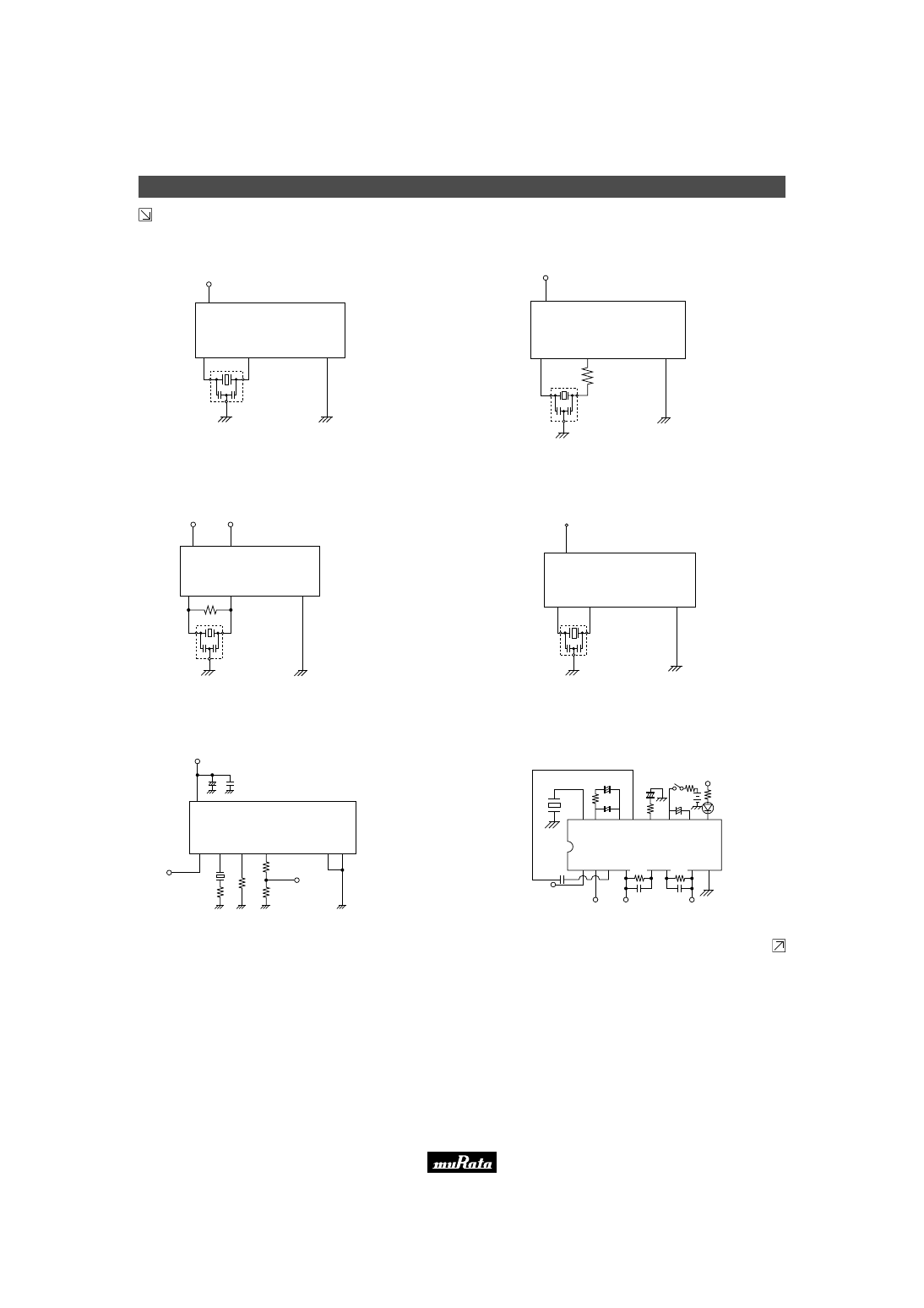
Utilizing Application Circuits
34
6
!
Note
• Please read rating and
!
CAUTION (for storage, operating, rating, soldering, mounting and handling) in this catalog to prevent smoking and/or burning, etc.
• This catalog has only typical specifications because there is no space for detailed specifications. Therefore, please approve our product specifications or transact the approval sheet for product specifications before ordering.
Continued from the preceding page.
■ uPD70F3102GJ (NEC)
32-bit Microcomputer
H
64
63
L
CSTCR6M60G55-R0
IC :
µ
PD70F3102
V
DD
(+3.3V)
H : 34,45,62,100,126,144
L : 9,35,65,71,83,117,135
C
1
C
2
C
1
=39pF
C
2
=39pF
■ CXD3068Q (SONY)
Digital Signal Processing IC for CD
H
V
DD
(+5V)
71
H : 1,28,47,56,61
L : 18,35,45,51,70
72
L
IC : CXD3068Q
CSTCE16M9V53-R0
C
1
C
2
C
1
=15pF
Rd
C
2
=15pF
Rd=220
Ω
■ LC895299 (SANYO)
Error Correction of CD-ROM LSI
H
1
H
2
V
DD1
(+5V)
V
DD2
(+3.3V)
93
Rf
CSTCW33M8X53-R0
H
1
: 21,39,52,65,86,88,94,112,
H
1
:
154,163,176
H
2
: 22,44,66,110,116,132,165
L : 1,23,24,40,45,51,58,67,73,89,
L :
91,109,111,125,133,139,155,164
92
L
IC : LC895299
C
1
C
2
■ TMP47C660AN (TOSHIBA)
4-bit Microcomputer
64
50
51
2,31,32
IC : TMP47C660AN
V
DD
(+5V)
CSTLS4M00G53-B0
C
1
=15pF
C
2
=15pF
C
1
C
2
■ TA8690AN (TOSHIBA)
TV Horizontal/Compatible with Synthesizer Circuit
V
CC
(+9.0V)
+
4
7
µ
F
0
.0
2
2
µ
F
25, 44
23
24
20
V
cont.
1
5
0
Ω
5
1
0
k
Ω
22
8
37
3
9
0
Ω
4
3
0
Ω
F
H
(1/32fosc.)
IC : TA8690AN
C
E
R
A
L
O
C
K
®
CERALOCK
®
: CSBLA503KEZZF46-B0
■ LA3410 (SANYO)
FM Stereo MPX
1
2
3
8
16 15
13
14
1
k
Ω
LA3410
4
5
C
S
B
L
A
4
5
6
K
E
2
Z
F
1
1
-B
0
0.047
µ
F
V
CC
(+12V)
INPUT
L
0.47
µ
F
3.3
µ
F
1
µ
F
V
CC
1
0
µ
F
11
10
9
12
3
5
0
k
Ω
+
−
750pF
62k
Ω
6
7
R
750pF
62k
Ω
VCO STOP
Continued on the following page.
Please read rating and
!
CAUTION (for storage, operating, rating, soldering, mounting and handling) in this PDF catalog to prevent smoking and/or burning, etc.
This catalog has only typical specifications. Therefore, you are requested to approve our product specifications or to transact the approval sheet for product specifications before ordering.
!
Note
P16E15.pdf 04.8.27
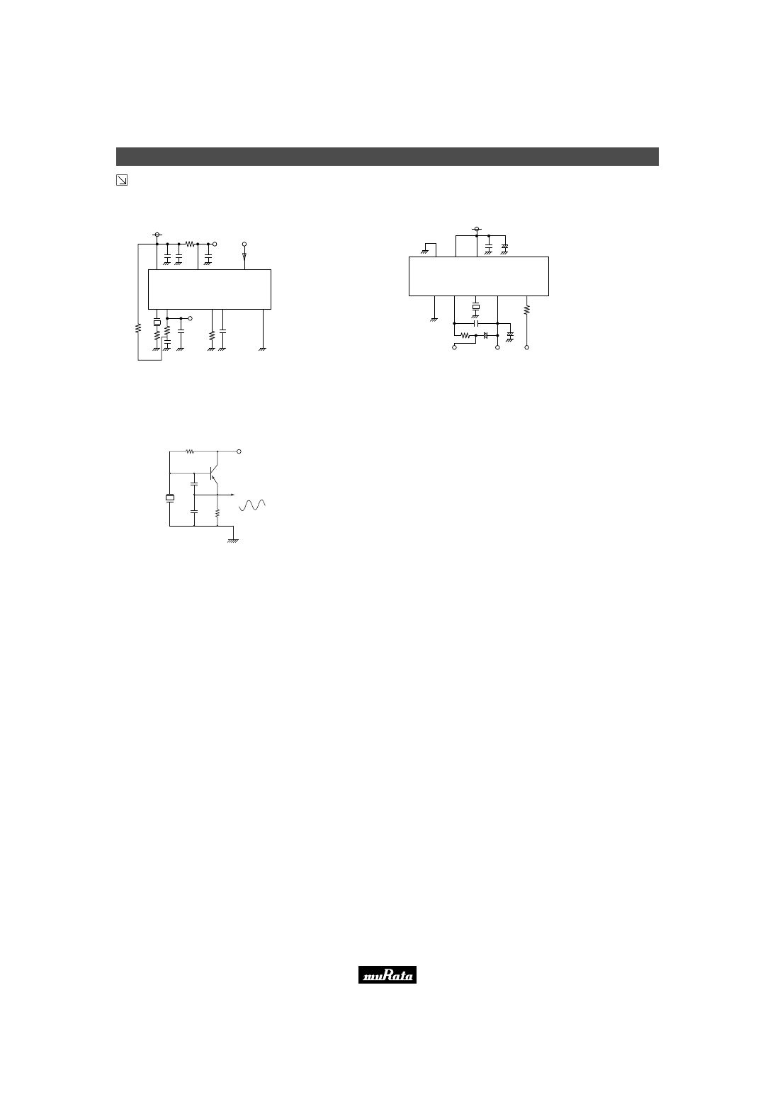
Utilizing Application Circuits
35
6
!
Note
• Please read rating and
!
CAUTION (for storage, operating, rating, soldering, mounting and handling) in this catalog to prevent smoking and/or burning, etc.
• This catalog has only typical specifications because there is no space for detailed specifications. Therefore, please approve our product specifications or transact the approval sheet for product specifications before ordering.
Continued from the preceding page.
■ TEA2130 (THOMSON)
TV Horizontal/Compatible with Synthesizer Circuit
Hout
CERALOCK
®
: CSBLA503KEZZF12-B0
Rs=470
Ω
Flyback In
5
11
13
17
9
18
3
V
CC
(+12.0V)
4
7
n
F
1k
Ω
1
0
0
µ
F
0
.0
1
µ
F
IC : TEA2130
C
E
R
A
L
O
C
K
®
R
s
2
.7
k
Ω
3
.9
k
Ω
3
3
n
F
1
0
0
n
F
3
.3
2
k
Ω
2
.2
µ
F
4
Vcont.
■ LA7687 (SANYO)
TV Horizontal/Compatible with Synthesizer Circuit
48
44
40
15
22
23
24
25
1.8k
Ω
3.3
µ
F
22
µ
F
0.033
µ
F
+
1
0
0
µ
F
0
.0
1
µ
F
V
CC
(+7.8V)
IC : LA7687
+
V
cont.
HVcc 13mA
Hout (fosc./32)
C
E
R
A
LO
C
K
®
+
3
3
0
k
Ω
CERALOCK
®
: CSBLA503KEZZF12-B0
■ Oscillation Circuit Incorporating Transistor
1
k
Ω
0
.0
0
1
µ
F
0
.0
0
5
µ
F
C
E
R
A
L
O
C
K
®
30k
Ω
-10V
Output
Recommendable Value
CERALOCK
®
: CSBLA455KEC8-B0
Please read rating and
!
CAUTION (for storage, operating, rating, soldering, mounting and handling) in this PDF catalog to prevent smoking and/or burning, etc.
This catalog has only typical specifications. Therefore, you are requested to approve our product specifications or to transact the approval sheet for product specifications before ordering.
!
Note
P16E15.pdf 04.8.27

Head Office
2-26-10, Tenjin Nagaokakyo-shi, Kyoto 617-8555, Japan Phone: 81-75-951-9111
As of October 12, 2004, Murata's contact information will be changed as follows
1-10-1, Higashi Kotari, Nagaokakyo-shi, Kyoto 617-8555, Japan
International Division
3-29-12, Shibuya, Shibuya-ku, Tokyo 150-0002, Japan
Phone: 81-3-5469-6123 Fax: 81-3-5469-6155 E-mail: intl@murata.co.jp
http://www.murata.com/
Please read rating and
!
CAUTION (for storage, operating, rating, soldering, mounting and handling) in this PDF catalog to prevent smoking and/or burning, etc.
This catalog has only typical specifications. Therefore, you are requested to approve our product specifications or to transact the approval sheet for product specifications before ordering.
!
Note
P16E15.pdf 04.8.27
Note:
1. Export Control
<
For customers outside Japan
>
Murata products should not be used or sold for use in the development, production, stockpiling or utilization of any conventional weapons or mass-destructive
weapons (nuclear weapons, chemical or biological weapons, or missiles), or any other weapons.
<
For customers in Japan
>
For products which are controlled items subject to the “Foreign Exchange and Foreign Trade Law” of Japan, the export license specified by the law is required
for export.
2. Please contact our sales representatives or product engineers before using the products in this catalog for the applications listed below, which require especially
high reliability for the prevention of defects which might directly damage to a third party's life, body or property, or when one of our products is intended for use
in applications other than those specified in this catalog.
q
Aircraft equipment
w
Aerospace equipment
e
Undersea equipment
r
Power plant equipment
t
Medical equipment
y
Transportation equipment (vehicles, trains, ships, etc.)
u
Traffic signal equipment
i
Disaster prevention / crime prevention equipment
o
Data-processing equipment
!0
Application of similar complexity and/or reliability requirements to the applications listed in the above
3. Product specifications in this catalog are as of July 2004. They are subject to change or our products in it may be discontinued without advance notice. Please
check with our sales representatives or product engineers before ordering. If there are any questions, please contact our sales representatives or product
engineers.
4. Please read rating and CAUTION (for storage, operating, rating, soldering, mounting and handling) in this catalog to prevent smoking and/or burning, etc.
5. This catalog has only typical specifications because there is no space for detailed specifications. Therefore, please approve our product specifications or
transact the approval sheet for product specifications before ordering.
6. Please note that unless otherwise specified, we shall assume no responsibility whatsoever for any conflict or dispute that may occur in connection with the effect
of our and/or a third party's intellectual property rights and other related rights in consideration of your use of our products and/or information described or
contained in our catalogs. In this connection, no representation shall be made to the effect that any third parties are authorized to use the rights mentioned
above under licenses without our consent.
7. No ozone depleting substances (ODS) under the Montreal Protocol are used in our manufacturing process.
Document Outline
- CONTENTS
- Part Numbering
- Chip Type Three Terminals CSTCC/R/E/G/V/W Series
- Chip Type Two Terminals CSACV/W Series
- MHz Chip Type Notice
- MHz Chip Type CSTC Series Packaging
- MHz Chip Type CSAC Series Packaging
- Lead Type Three Terminals CSTLS Series
- Lead Type Two Terminals CSALS Series
- MHz Lead Type Notice
- MHz Lead Type CSTLS Series Packaging
- MHz Lead Type CSALS Series Packaging
- Chip Type Two Terminals CSBFB Series
- Lead Type Two Terminals CSBLA Series
- kHz Lead Type Notice
- kHz Type Notice
- kHz Type Packaging
- Utilizing Application Circuits
Wyszukiwarka
Podobne podstrony:
01 OBRÓBKA GÓRNA OKNA UKŁAD POZIOMY MUR
02 OŚCIEŻE OKNA UKŁAD POZIOMY MUR
06 OŚCIEŻE OKNA UKŁAD PIONOWY MUR
08 NAROŻNIK ZEWNĘTRZNY UKŁAD PIONOWY MUR
mur 3
01 ATTYKA UKŁAD POZIOMY MUR
Chiński mur Big Cyc
mur ZB2NB5ZAE4BFD45KSD7MI55JCRKDPE66STMFNKY
Cegła mur
ot mur
Na mur beton komórkowy (2)
01 PARAPET OKNA UKŁAD POZIOMY MUR
04 ATTYKA UKŁAD PIONOWY MUR
mur 6
01 NAROŻNIK ZEWNĘTRZNY UKŁAD POZIOMY MUR
05 NAROŻNIK ZEWNĘTRZNY UKŁAD POZIOMY MUR
mur oporowy EC7(1)
więcej podobnych podstron