✂
✂
✂
✂
✂
✂
✂
✂
Campo di applicazione
Il presente cablaggio si utilizza, in abbinamento al connettore 6
poli di collegamento iniettori benzina presente sul cablaggio
Sequent 24, in alternativa ai cablaggi Sequent 24 di collegamento
iniettori benzina destro o sinistro.
Questo può avvenire principalmente in presenza di iniettori con
connettori di forma diversa da quelli utilizzati nei cablaggi destro o
sinistro o per mancanza di spazio.
Schema di installazione
Per una corretta installazione del presente cablaggio, è necessa-
rio attenersi alle seguenti istruzioni.
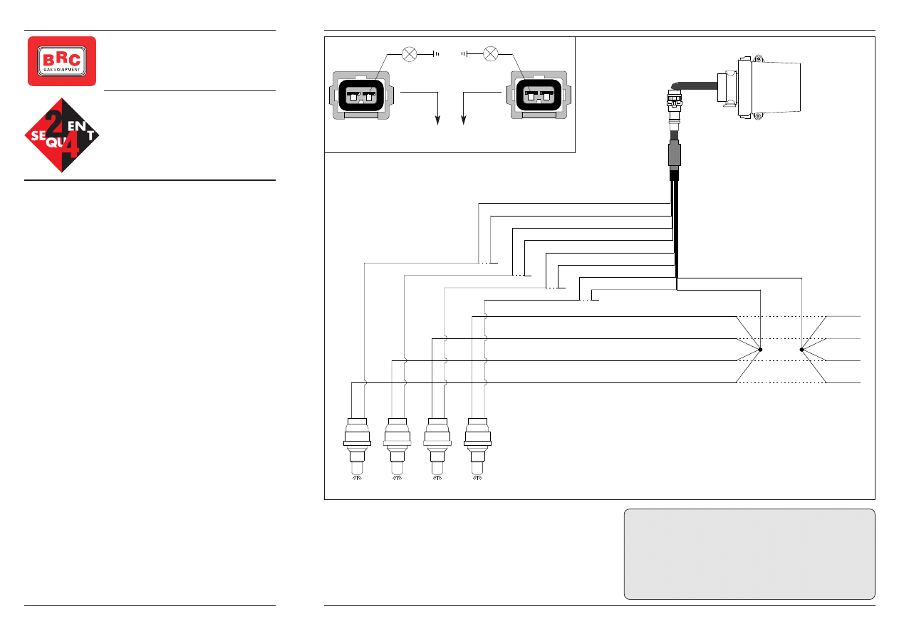
1 - Disinserire i connettori di TUTTI gli iniettori e se necessario
eventuali altri connettori situati a monte degli stessi (previo con-
tatto del servizio di assistenza BRC).
2 - Accendere il quadro.
3 - T entando l’avviamento individuare quale pin sui connettori
femmina appena smontati reca una tensione di + 12V (usare la
lampadina spia o, se possibile, l'apposito strumento POLAR cod.
06LB00001093) [Verificarli tutti!!]. Questo pin sarà il positivo iniet-
tori.
4 - Tagliare il filo positivo di ciascun iniettore. Collegare i capi
rivolti verso l’iniettore con il filo BIANCO/MARRONE del caglag-
gio Sequent 24 e gli altri capi rivolti verso la centralina iniezione
benzina con il filo BIANCO/VERDE del cablaggio Sequent 24
(vedi Fig. 1).
ATTENZIONE: questi collegamenti appena descritti devono esse-
re fatti il più vicino possibile alle connessioni con gli iniettori.
5 - Tagliare il filo negativo e collegare il capo del filo rivolto verso
l'iniettore al filo ARANCIO del cablaggio Sequent 24 e il capo del
filo rivolto verso la centralina iniezione benzina al filo VIOLA del
cablaggio Sequent 24.
Tagliare ed isolare eventuali fili Arancio e Viola non utilizzati (Es:
CABLAGGIO SEQUENT 24
COLLEGAMENTO
4 INIETTORI BENZINA
UNIVERSALE
codice 06LB50010121
AVVERTENZE:
- La M.T.M. S.r.l. declina ogni responsabilità per danni a cose e/o
persone derivanti da un utilizzo errato o da manomissione di
propri dispositivi da parte di personale non autorizzato.
M.T.M. s.r.l.
Via La Morra, 1
12062 CHERASCO (CN) - ITALY
Assistenza Tecnica: 0172 4860140
FI010104 del 14.06.04
Negativo
Positivo
Negativo
Positivo
Negativo
Positivo
Negativo
Positivo
V
iola
Arancio
V
iola
Arancio
V
iola
Arancio
V
iola
Arancio
Inj. 1 Benz
Inj. 1 Benz
Inj. 2 Benz
Inj. 2 Benz
Inj. 4 Benz
Inj. 4 Benz
Inj. 3 Benz
Inj. 3 Benz
Bianco/Verde
Bianco/Marrone
auto a 3 cilindri).
E’ importante mantenere durante il funzionamento a gas la stessa
sequenza di iniezione che si ha nel funzionamento a benzina. E’
quindi necessario interrompere i segnali negativi degli iniettori
benzina con lo stesso ordine con cui verranno collegati gli iniettori
gas. A tal proposito sui fili Arancio e Viola del cablaggio sono indi-
cati i relativi iniettori da tagliare.
SEQUENT 24
1° Iniettore 2° Iniettore 3° Iniettore 4° Iniettore
Lampadina spia
accesa oppure
LED “SX” Polar
Connettore
iniettore
originale
Lampadina spia
accesa oppure
LED “DX” Polar
Seguire indicazioni
di paragrafo 4
Seguire indicazioni
di paragrafo 4
Connettore
iniettore
originale
Fig. 1
✂
✂
✂
✂
✂
✂
✂
✂
Field of application
This harness is together with the Sequent 24 6-pole petrol injector
connector, as option to Sequent 24 right or left petrol injectors
connector harnesses. This could mainly occur when injectors
have a different shape compared to right or left harnesses or in
case of not available space.
Installation diagram
For a correct installation of this harness, it is necessary to follow
these instructions.
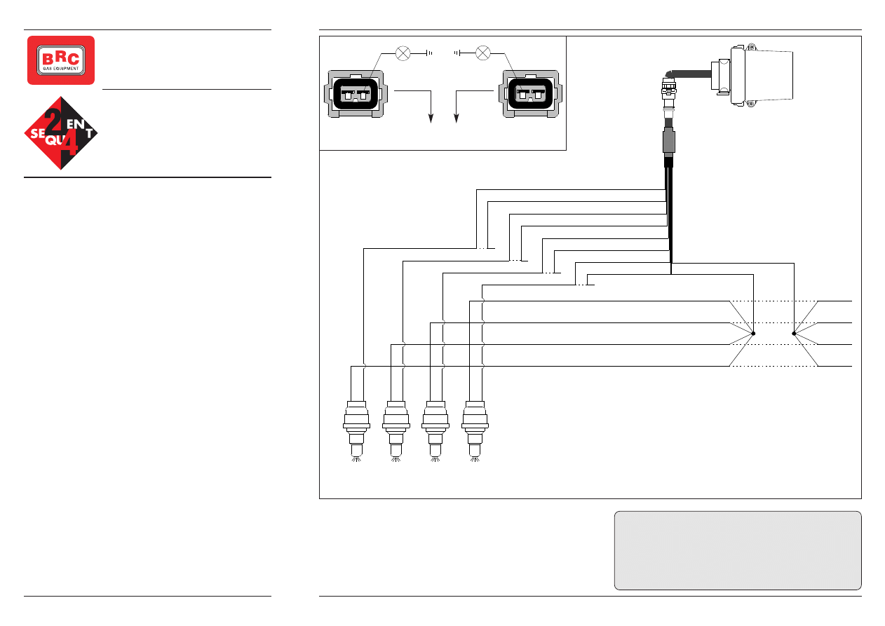
1 - Disconnect the connectors of ALL injectors and, if necessary,
also the other possible connectors placed upstream of the injec-
tors (by previous agreement with the BRC after-sales service).
2 - Switch the dashboard on.
3 - Find out which pin on the just disconnected female connectors
has a +12V voltage trying to start the vehicle (use the check lamp
or, if possible, the special "Polar" device code 06LB00001093).
[Verify all of them !!!] This pin is the injector positive.
4 – Cut the positive wire of each injector and connect the ends
towards the injectors to the White/Brown wire of the Sequent 24
harness and the other ends towards the petrol injection ECU to
the White/Green one (see picture 1)
CAUTION: the above connections has to be carried out as near-
est as possible to the injectors junctions.
5 – Cut the negative wire and connect the end going to the injec-
tor to the ORANGE wire of the Sequent 24 harness and the other
end going to the petrol injection ECU to the VIOLET wire.
Cut and isolate Orange and Violet wires if not used (i.e. for 3
cylinders vehicles)
During gas operation it is important to keep the same injection
sequence you have during petrol operation.
It is then necessary to stop negative signals of petrol injectors
with the same order followed to connect gas injectors. In this case
UNIVERSAL
4-PETROL INJECTOR
CONNECTION
SEQUENT 24 HARNESS
code 06LB50010121
WARNING:
- The M.T.M. S.r.l. Co. declines all responsibilities for damages
to things and/or people coming from an incorrect use or from a
tempering of the devices by unauthorised personnel.
M.T.M. s.r.l.
Via La Morra, 1
12062 CHERASCO (CN) - ITALY
After-Sales Service: 0172 4860140
FI010104 dd 14.06.04
Negative
Positive
Negative
Positive
Negative
Positive
Negative
Positive
V
iolet
Orange
V
iolet
Orange
V
iolet
Orange
V
iolet
Orange
Inj. 1 Petr
Inj. 1 Petr
Inj. 2 Petr
Inj. 2 Petr
Inj. 4 Petr
Inj. 4 Petr
Inj. 3 Petr
Inj. 3 Petr
White/Green
White/Brown
of Orange and Violet wire there is the indication for the injectors
that have to be cut.
SEQUENT 24
1° Injector 2° Injector 3° Injector 4° Injector
Warning light on
or
LED “SX” Polar
Follow the indi-
cation in the § 4.
Original
injector
Connector
Warning light on
or
LED “DX” Polar
Follow the indi-
cation in the § 4.
Original
injector
Connector
Pic. 1
Wyszukiwarka
Podobne podstrony:
SQ24 Cabl 4INJ FI010105 ml
ML 2551
ML Obliczenia konstrukcyjno sprawdzające
odpowiedzi ml, SGGW WIP ZIP 2009, różne
A4 ruba ML
ćw 6 JR MT ML
ml zaliczenie gotowce 2
test kompetencji dla klas 5 ml
Sprawozdanie ML
opisy ML
DZIENNIK POMIARU DŁUGOŚCI PROSTEJ M?ZP MŁ
normy mł 1 QTLEY3JNJLLYASNNVY62TTTE3BYFI7NNOGLSJBI
instrukcja bhp przy obsludze ml Nieznany (4)
ml uml
ML
ML sprawozdanie2
więcej podobnych podstron