Industrial Robots, Safety
With KR C4
KUKA Roboter GmbH
Issued: 21.06.2012
Version: Sicherheit KR C4 V7 en (PDF)

Industrial Robots, Safety
Issued: 21.06.2012 Version: Sicherheit KR C4 V7 en (PDF)
© Copyright 2012
KUKA Roboter GmbH
Zugspitzstraße 140
D-86165 Augsburg
Germany
This documentation or excerpts therefrom may not be reproduced or disclosed to third parties without
the express permission of KUKA Roboter GmbH.
Other functions not described in this documentation may be operable in the controller. The user has
no claims to these functions, however, in the case of a replacement or service work.
We have checked the content of this documentation for conformity with the hardware and software
described. Nevertheless, discrepancies cannot be precluded, for which reason we are not able to
guarantee total conformity. The information in this documentation is checked on a regular basis, how-
ever, and necessary corrections will be incorporated in the subsequent edition.
Subject to technical alterations without an effect on the function.
Translation of the original documentation
KIM-PS5-DOC
Publication:
Pub Sicherheit KR C4 en
Bookstructure:
Sicherheit KR C4 V3.1
Version:
Sicherheit KR C4 V7 en (PDF)

Issued: 21.06.2012 Version: Sicherheit KR C4 V7 en (PDF)
Contents
..................................................................................................
5
Representation of warnings and notes ......................................................................
5
............................................................................................................
7
General ......................................................................................................................
7
Liability ..................................................................................................................
7
Intended use of the industrial robot ......................................................................
7
EC declaration of conformity and declaration of incorporation .............................
8
Terms used ...........................................................................................................
8
Personnel ...................................................................................................................
10
Workspace, safety zone and danger zone .................................................................
11
Triggers for stop reactions .........................................................................................
12
Safety functions .........................................................................................................
13
Overview of the safety functions ...........................................................................
13
Safety controller ....................................................................................................
14
Mode selection ......................................................................................................
14
Operator safety .....................................................................................................
14
EMERGENCY STOP device ................................................................................
15
Logging off the higher-level safety controller ........................................................
15
External EMERGENCY STOP device ..................................................................
16
Enabling device ....................................................................................................
16
External enabling device .......................................................................................
17
External safe operational stop ..............................................................................
17
External safety stop 1 and external safety stop 2 .................................................
17
Velocity monitoring in T1 ......................................................................................
17
Additional protective equipment .................................................................................
17
Jog mode ..............................................................................................................
17
Software limit switches .........................................................................................
17
Mechanical end stops ...........................................................................................
18
Mechanical axis range limitation (optional) ...........................................................
18
Axis range monitoring (optional) ...........................................................................
18
Devices for moving the manipulator without the robot controller (options) ...........
18
Labeling on the industrial robot .............................................................................
20
External safeguards ..............................................................................................
20
Overview of operating modes and safety functions ...................................................
21
Safety measures ........................................................................................................
21
General safety measures ......................................................................................
21
Transportation .......................................................................................................
22
Start-up and recommissioning ..............................................................................
22
Start-up mode .......................................................................................................
24
Manual mode ........................................................................................................
25
Simulation .............................................................................................................
26
Automatic mode ....................................................................................................
26
Maintenance and repair ........................................................................................
26
Decommissioning, storage and disposal ..............................................................
28
Safety measures for “single point of control” ........................................................
28
Applied norms and regulations ..................................................................................
29
Contents

Issued: 21.06.2012 Version: Sicherheit KR C4 V7 en (PDF)
1 Introduction
1
Introduction
1.1
Representation of warnings and notes
Safety
These warnings are relevant to safety and must be observed.
Notes
These hints serve to make your work easier or contain references to further
information.
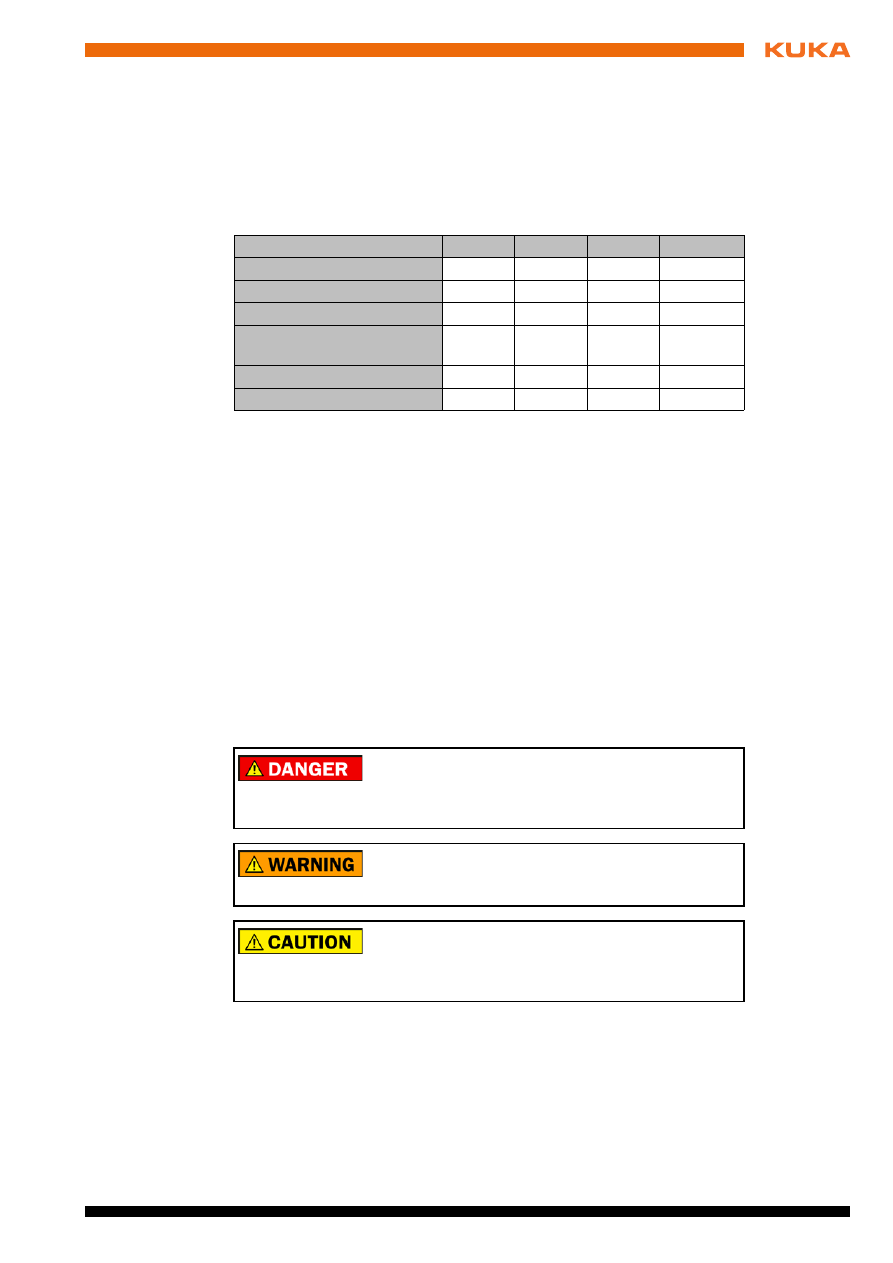
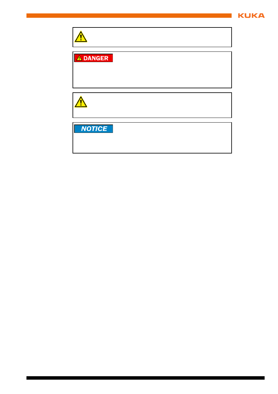
These warnings mean that it is certain or highly probable
that death or severe injuries will occur, if no precautions
are taken.
These warnings mean that death or severe injuries may
occur, if no precautions are taken.
These warnings mean that minor injuries may occur, if
no precautions are taken.
These warnings mean that damage to property may oc-
cur, if no precautions are taken.
These warnings contain references to safety-relevant information or
general safety measures. These warnings do not refer to individual
hazards or individual precautionary measures.
Tip to make your work easier or reference to further information.


Issued: 21.06.2012 Version: Sicherheit KR C4 V7 en (PDF)
2 Safety
2
Safety
2.1
General
2.1.1
Liability
The device described in this document is either an industrial robot or a com-
ponent thereof.
Components of the industrial robot:
Manipulator
Robot controller
Teach pendant
Connecting cables
External axes (optional)
e.g. linear unit, turn-tilt table, positioner
Software
Options, accessories
The industrial robot is built using state-of-the-art technology and in accor-
dance with the recognized safety rules. Nevertheless, misuse of the industrial
robot may constitute a risk to life and limb or cause damage to the industrial
robot and to other material property.
The industrial robot may only be used in perfect technical condition in accor-
dance with its intended use and only by safety-conscious persons who are ful-
ly aware of the risks involved in its operation. Use of the industrial robot is
subject to compliance with this document and with the declaration of incorpo-
ration supplied together with the industrial robot. Any functional disorders af-
fecting the safety of the industrial robot must be rectified immediately.
Safety infor-
mation
Safety information cannot be held against KUKA Roboter GmbH. Even if all
safety instructions are followed, this is not a guarantee that the industrial robot
will not cause personal injuries or material damage.
No modifications may be carried out to the industrial robot without the autho-
rization of KUKA Roboter GmbH. Additional components (tools, software,
etc.), not supplied by KUKA Roboter GmbH, may be integrated into the indus-
trial robot. The user is liable for any damage these components may cause to
the industrial robot or to other material property.
In addition to the Safety chapter, this document contains further safety instruc-
tions. These must also be observed.
2.1.2
Intended use of the industrial robot
The industrial robot is intended exclusively for the use designated in the “Pur-
pose” chapter of the operating instructions or assembly instructions.
Using the industrial robot for any other or additional purpose is considered im-
permissible misuse. The manufacturer cannot be held liable for any damage
resulting from such use. The risk lies entirely with the user.
Operating the industrial robot and its options within the limits of its intended
use also involves observance of the operating and assembly instructions for
Further information is contained in the “Purpose” chapter of the oper-
ating instructions or assembly instructions of the industrial robot.

Issued: 21.06.2012 Version: Sicherheit KR C4 V7 en (PDF)
the individual components, with particular reference to the maintenance spec-
ifications.
Misuse
Any use or application deviating from the intended use is deemed to be imper-
missible misuse. This includes e.g.:
Transportation of persons and animals
Use as a climbing aid
Operation outside the permissible operating parameters
Use in potentially explosive environments
Operation without additional safeguards
Outdoor operation
2.1.3
EC declaration of conformity and declaration of incorporation
This industrial robot constitutes partly completed machinery as defined by the
EC Machinery Directive. The industrial robot may only be put into operation if
the following preconditions are met:
The industrial robot is integrated into a complete system.
Or: The industrial robot, together with other machinery, constitutes a com-
plete system.
Or: All safety functions and safeguards required for operation in the com-
plete machine as defined by the EC Machinery Directive have been added
to the industrial robot.
The complete system complies with the EC Machinery Directive. This has
been confirmed by means of an assessment of conformity.
Declaration of
conformity
The system integrator must issue a declaration of conformity for the complete
system in accordance with the Machinery Directive. The declaration of confor-
mity forms the basis for the CE mark for the system. The industrial robot must
be operated in accordance with the applicable national laws, regulations and
standards.
The robot controller is CE certified under the EMC Directive and the Low Volt-
age Directive.
Declaration of
incorporation
The industrial robot as partly completed machinery is supplied with a declara-
tion of incorporation in accordance with Annex II B of the EC Machinery Direc-
tive 2006/42/EC. The assembly instructions and a list of essential
requirements complied with in accordance with Annex I are integral parts of
this declaration of incorporation.
The declaration of incorporation declares that the start-up of the partly com-
pleted machinery remains impermissible until the partly completed machinery
has been incorporated into machinery, or has been assembled with other parts
to form machinery, and this machinery complies with the terms of the EC Ma-
chinery Directive, and the EC declaration of conformity is present in accor-
dance with Annex II A.
The declaration of incorporation, together with its annexes, remains with the
system integrator as an integral part of the technical documentation of the
complete machinery.
2.1.4
Terms used
STOP 0, STOP 1 and STOP 2 are the stop definitions according to EN 60204-
1:2006.
Issued: 21.06.2012 Version: Sicherheit KR C4 V7 en (PDF)
2 Safety
Term
Description
Axis range
Range of each axis, in degrees or millimeters, within which it may move.
The axis range must be defined for each axis.
Stopping distance
Stopping distance = reaction distance + braking distance
The stopping distance is part of the danger zone.
Workspace
The manipulator is allowed to move within its workspace. The work-
space is derived from the individual axis ranges.
Operator
(User)
The user of the industrial robot can be the management, employer or
delegated person responsible for use of the industrial robot.
Danger zone
The danger zone consists of the workspace and the stopping distances.
Service life
The service life of a safety-relevant component begins at the time of
delivery of the component to the customer.
The service life is not affected by whether the component is used in a
robot controller or elsewhere or not, as safety-relevant components are
also subject to ageing during storage.
KCP
The KCP (KUKA Control Panel) teach pendant has all the operator con-
trol and display functions required for operating and programming the
industrial robot.
The KCP variant for the KR C4 is called KUKA smartPAD. The general
term “KCP”, however, is generally used in this documentation.
Manipulator
The robot arm and the associated electrical installations
Safety zone
The safety zone is situated outside the danger zone.
Safe operational stop
The safe operational stop is a standstill monitoring function. It does not
stop the robot motion, but monitors whether the robot axes are station-
ary. If these are moved during the safe operational stop, a safety stop
STOP 0 is triggered.
The safe operational stop can also be triggered externally.
When a safe operational stop is triggered, the robot controller sets an
output to the field bus. The output is set even if not all the axes were sta-
tionary at the time of triggering, thereby causing a safety stop STOP 0 to
be triggered.
Safety STOP 0
A stop that is triggered and executed by the safety controller. The safety
controller immediately switches off the drives and the power supply to
the brakes.
Note:
This stop is called safety STOP 0 in this document.
Safety STOP 1
A stop that is triggered and monitored by the safety controller. The brak-
ing process is performed by the non-safety-oriented part of the robot
controller and monitored by the safety controller. As soon as the manip-
ulator is at a standstill, the safety controller switches off the drives and
the power supply to the brakes.
When a safety STOP 1 is triggered, the robot controller sets an output to
the field bus.
The safety STOP 1 can also be triggered externally.
Note:
This stop is called safety STOP 1 in this document.
Issued: 21.06.2012 Version: Sicherheit KR C4 V7 en (PDF)
2.2
Personnel
The following persons or groups of persons are defined for the industrial robot:
User
Personnel
User
The user must observe the labor laws and regulations. This includes e.g.:
The user must comply with his monitoring obligations.
The user must carry out instructions at defined intervals.
Personnel
Personnel must be instructed, before any work is commenced, in the type of
work involved and what exactly it entails as well as any hazards which may ex-
ist. Instruction must be carried out regularly. Instruction is also required after
particular incidents or technical modifications.
Personnel includes:
System integrator
Operators, subdivided into:
Start-up, maintenance and service personnel
Operating personnel
Safety STOP 2
A stop that is triggered and monitored by the safety controller. The brak-
ing process is performed by the non-safety-oriented part of the robot
controller and monitored by the safety controller. The drives remain acti-
vated and the brakes released. As soon as the manipulator is at a stand-
still, a safe operational stop is triggered.
When a safety STOP 2 is triggered, the robot controller sets an output to
the field bus.
The safety STOP 2 can also be triggered externally.
Note:
This stop is called safety STOP 2 in this document.
Stop category 0
The drives are deactivated immediately and the brakes are applied. The
manipulator and any external axes (optional) perform path-oriented
braking.
Note:
This stop category is called STOP 0 in this document.
Stop category 1
The manipulator and any external axes (optional) perform path-main-
taining braking. The drives are deactivated after 1 s and the brakes are
applied.
Note:
This stop category is called STOP 1 in this document.
Stop category 2
The drives are not deactivated and the brakes are not applied. The
manipulator and any external axes (optional) are braked with a path-
maintaining braking ramp.
Note:
This stop category is called STOP 2 in this document.
System integrator
(plant integrator)
System integrators are people who safely integrate the industrial robot
into a complete system and commission it.
T1
Test mode, Manual Reduced Velocity (<= 250 mm/s)
T2
Test mode, Manual High Velocity (> 250 mm/s permissible)
External axis
Motion axis which is not part of the manipulator but which is controlled
using the robot controller, e.g. KUKA linear unit, turn-tilt table, Posiflex.
Term
Description
All persons working with the industrial robot must have read and un-
derstood the industrial robot documentation, including the safety
chapter.
Issued: 21.06.2012 Version: Sicherheit KR C4 V7 en (PDF)
2 Safety
Cleaning personnel
System integrator
The industrial robot is safely integrated into a complete system by the system
integrator.
The system integrator is responsible for the following tasks:
Installing the industrial robot
Connecting the industrial robot
Performing risk assessment
Implementing the required safety functions and safeguards
Issuing the declaration of conformity
Attaching the CE mark
Creating the operating instructions for the complete system
Operator
The operator must meet the following preconditions:
The operator must be trained for the work to be carried out.
Work on the industrial robot must only be carried out by qualified person-
nel. These are people who, due to their specialist training, knowledge and
experience, and their familiarization with the relevant standards, are able
to assess the work to be carried out and detect any potential hazards.
Example
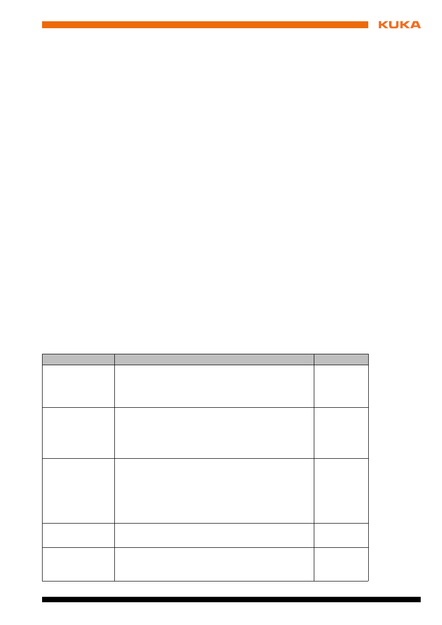
The tasks can be distributed as shown in the following table.
2.3
Workspace, safety zone and danger zone
Workspaces are to be restricted to the necessary minimum size. A workspace
must be safeguarded using appropriate safeguards.
Installation, exchange, adjustment, operation, maintenance and re-
pair must be performed only as specified in the operating or assembly
instructions for the relevant component of the industrial robot and only
by personnel specially trained for this purpose.
Tasks
Operator
Programmer
System inte-
grator
Switch robot controller
on/off
x
x
x
Start program
x
x
x
Select program
x
x
x
Select operating mode
x
x
x
Calibration
(tool, base)
x
x
Master the manipulator
x
x
Configuration
x
x
Programming
x
x
Start-up
x
Maintenance
x
Repair
x
Decommissioning
x
Transportation
x
Work on the electrical and mechanical equipment of the industrial ro-
bot may only be carried out by specially trained personnel.
12 / 33
Issued: 21.06.2012 Version: Sicherheit KR C4 V7 en (PDF)
The safeguards (e.g. safety gate) must be situated inside the safety zone. In
the case of a stop, the manipulator and external axes (optional) are braked
and come to a stop within the danger zone.
The danger zone consists of the workspace and the stopping distances of the
manipulator and external axes (optional). It must be safeguarded by means of
physical safeguards to prevent danger to persons or the risk of material dam-
age.
2.4
Triggers for stop reactions
Stop reactions of the industrial robot are triggered in response to operator ac-
tions or as a reaction to monitoring functions and error messages. The follow-
ing tables show the different stop reactions according to the operating mode
that has been set.
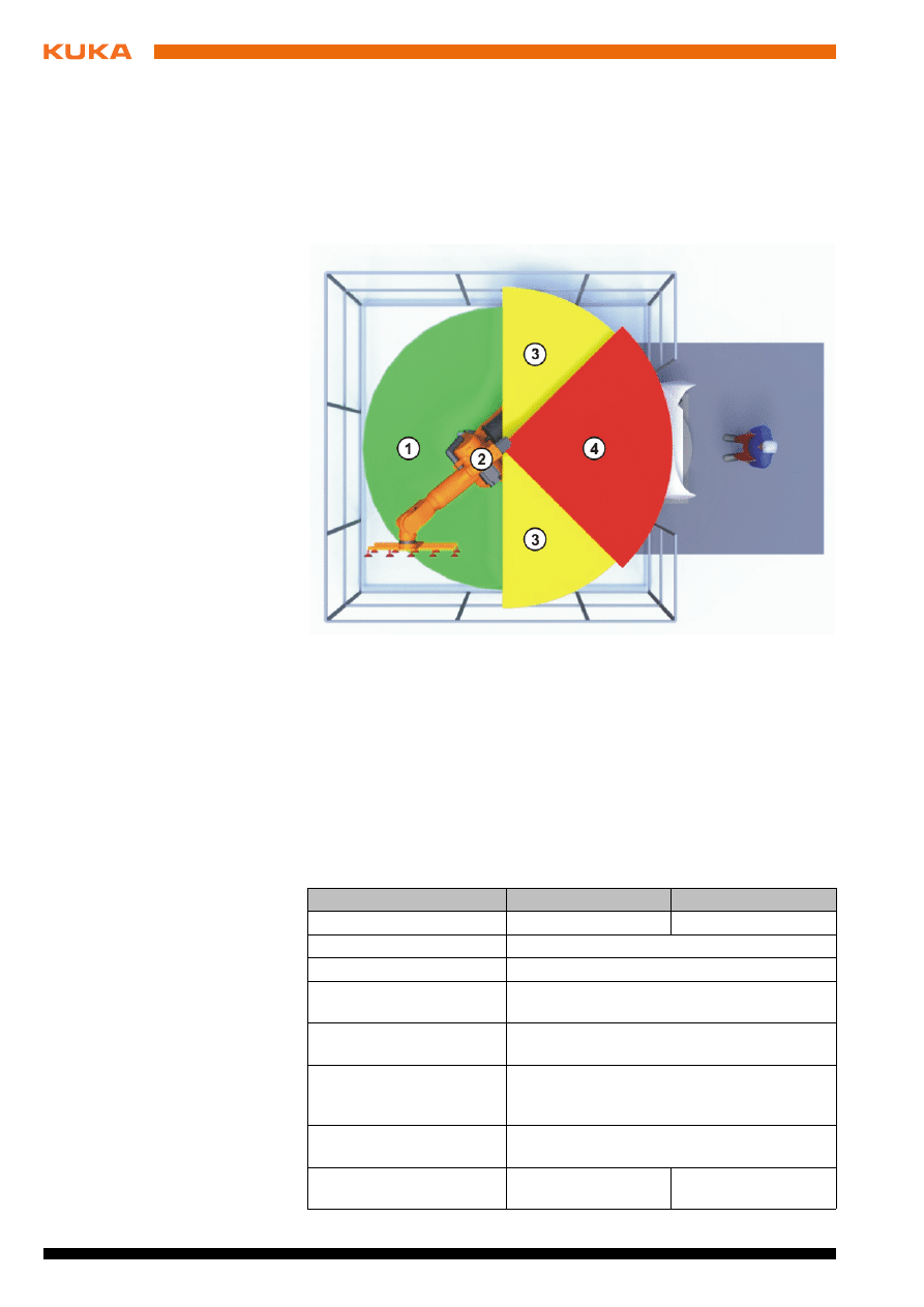
Fig. 2-1: Example of axis range A1
1
Workspace
3
Stopping distance
2
Manipulator
4
Safety zone
Trigger
T1, T2
AUT, AUT EXT
Start key released
STOP 2
-
STOP key pressed
STOP 2
Drives OFF
STOP 1
“Motion enable” input
drops out
STOP 2
Robot controller switched
off (power failure)
STOP 0
Internal error in non-
safety-oriented part of the
robot controller
STOP 0 or STOP 1
(dependent on the cause of the error)
Operating mode changed
during operation
Safety stop 2
Safety gate opened (oper-
ator safety)
-
Safety stop 1
Issued: 21.06.2012 Version: Sicherheit KR C4 V7 en (PDF)
2 Safety
2.5
Safety functions
2.5.1
Overview of the safety functions
The following safety functions are present in the industrial robot:
Mode selection
Operator safety (= connection for the guard interlock)
EMERGENCY STOP device
Enabling device
External safe operational stop
External safety stop 1 (not for the controller variant “KR C4 compact”)
External safety stop 2
Velocity monitoring in T1
The safety functions of the industrial robot meet the following requirements:
Category 3
and Performance Level d in accordance with EN ISO 13849-
1:2008
SIL 2
according to EN 62061
The requirements are only met on the following condition, however:
The EMERGENCY STOP device is pressed at least once every 6 months.
The following components are involved in the safety functions:
Safety controller in the control PC
KUKA Control Panel (KUKA smartPAD)
Cabinet Control Unit (CCU)
Resolver Digital Converter (RDC)
KUKA Power Pack (KPP)
KUKA Servo Pack (KSP)
Safety Interface Board (SIB) (if used)
There are also interfaces to components outside the industrial robot and to
other robot controllers.
Enabling switch released
Safety stop 2
-
Enabling switch pressed
fully down or error
Safety stop 1
-
E-STOP pressed
Safety stop 1
Error in safety controller
or periphery of the safety
controller
Safety stop 0
Trigger
T1, T2
AUT, AUT EXT
In the absence of operational safety functions and safe-
guards, the industrial robot can cause personal injury or
material damage. If safety functions or safeguards are dismantled or deacti-
vated, the industrial robot may not be operated.
During system planning, the safety functions of the overall system
must also be planned and designed. The industrial robot must be in-
tegrated into this safety system of the overall system.
14 / 33
Issued: 21.06.2012 Version: Sicherheit KR C4 V7 en (PDF)
2.5.2
Safety controller
The safety controller is a unit inside the control PC. It links safety-relevant sig-
nals and safety-relevant monitoring functions.
Safety controller tasks:
Switching off the drives; applying the brakes
Monitoring the braking ramp
Standstill monitoring (after the stop)
Velocity monitoring in T1
Evaluation of safety-relevant signals
Setting of safety-oriented outputs
2.5.3
Mode selection
The industrial robot can be operated in the following modes:
Manual Reduced Velocity (T1)
Manual High Velocity (T2)
Automatic (AUT)
Automatic External (AUT EXT)
2.5.4
Operator safety
The operator safety signal is used for interlocking physical safeguards, e.g.
safety gates. Automatic operation is not possible without this signal. In the
event of a loss of signal during automatic operation (e.g. safety gate is
opened), the manipulator stops with a safety stop 1.
Operator safety is not active in the test modes T1 (Manual Reduced Velocity)
and T2 (Manual High Velocity).
Do not change the operating mode while a program is running. If the
operating mode is changed during program execution, the industrial
robot is stopped with a safety stop 2.
Operat-
ing mode
Use
Velocities
T1
For test operation, pro-
gramming and teach-
ing
Program verification:
Programmed velocity, maxi-
mum 250 mm/s
Jog mode:
Jog velocity, maximum 250 mm/
s
T2
For test operation
Program verification:
Programmed velocity
Jog mode: Not possible
AUT
For industrial robots
without higher-level
controllers
Program mode:
Programmed velocity
Jog mode: Not possible
AUT EXT
For industrial robots
with higher-level con-
trollers, e.g. PLC
Program mode:
Programmed velocity
Jog mode: Not possible
Issued: 21.06.2012 Version: Sicherheit KR C4 V7 en (PDF)
2 Safety
2.5.5
EMERGENCY STOP device
The EMERGENCY STOP device for the industrial robot is the EMERGENCY
STOP device on the KCP. The device must be pressed in the event of a haz-
ardous situation or emergency.
Reactions of the industrial robot if the EMERGENCY STOP device is pressed:
The manipulator and any external axes (optional) are stopped with a safe-
ty stop 1.
Before operation can be resumed, the EMERGENCY STOP device must be
turned to release it.
There must always be at least one external EMERGENCY STOP device in-
stalled. This ensures that an EMERGENCY STOP device is available even
when the KCP is disconnected.
(
>>>
2.5.7 "External EMERGENCY STOP device" Page 16)
2.5.6
Logging off the higher-level safety controller
If the robot controller is connected to a higher-level safety controller, switching
off the robot controller inevitably terminates this connection.
If the X11 interface is used, this triggers an EMERGENCY STOP for the
overall system.
If the PROFIsafe interface is used, the KUKA safety controller generates
a signal that prevents the higher-level controller from triggering an EMER-
GENCY STOP for the overall system.
Following a loss of signal, automatic operation must not
be resumed merely by closing the safeguard; it must first
additionally be acknowledged. It is the responsibility of the system integrator
to ensure this. This is to prevent automatic operation from being resumed in-
advertently while there are still persons in the danger zone, e.g. due to the
safety gate closing accidentally.
The acknowledgement must be designed in such a way that an actual
check of the danger zone can be carried out first. Acknowledgement
functions that do not allow this (e.g. because they are automatically trig-
gered by closure of the safeguard) are not permissible.
Failure to observe this may result in death to persons, severe injuries or
considerable damage to property.
Tools and other equipment connected to the manipulator
must be integrated into the EMERGENCY STOP circuit
on the system side if they could constitute a potential hazard.
Failure to observe this precaution may result in death, severe injuries or con-
siderable damage to property.
If the PROFIsafe interface is used: In his risk assess-
ment, the system integrator must take into consideration
whether the fact that switching off the robot controller does not trigger an
EMERGENCY STOP of the overall system could constitute a hazard and, if
so, how this hazard can be countered.
Failure to take this into consideration may result in death to persons, severe
injuries or considerable damage to property.
16 / 33
Issued: 21.06.2012 Version: Sicherheit KR C4 V7 en (PDF)
2.5.7
External EMERGENCY STOP device
There must be EMERGENCY STOP devices available at every operator sta-
tion that can initiate a robot motion or other potentially hazardous situation.
The system integrator is responsible for ensuring this.
There must always be at least one external EMERGENCY STOP device in-
stalled. This ensures that an EMERGENCY STOP device is available even
when the KCP is disconnected.
External EMERGENCY STOP devices are connected via the customer inter-
face. External EMERGENCY STOP devices are not included in the scope of
supply of the industrial robot.
2.5.8
Enabling device
The enabling devices of the industrial robot are the enabling switches on the
KCP.
There are 3 enabling switches installed on the KCP. The enabling switches
have 3 positions:
Not pressed
Center position
Panic position
In the test modes, the manipulator can only be moved if one of the enabling
switches is held in the central position.
Releasing the enabling switch triggers a safety stop 2.
Pressing the enabling switch down fully (panic position) triggers a safety
stop 1.
It is possible, for a short time, to hold 2 enabling switches in the center po-
sition simultaneously. This makes it possible to adjust grip from one en-
abling switch to another one. If 2 enabling switches are held
simultaneously in the center position for a longer period of time, this trig-
gers a safety stop after several seconds.
If an enabling switch malfunctions (jams), the industrial robot can be stopped
using the following methods:
Press the enabling switch down fully
Actuate the EMERGENCY STOP system
Release the Start key
If a robot controller is switched off, the E-STOP device on
the KCP is no longer functional. The user is responsible
for ensuring that the KCP is either covered or removed from the system. This
serves to prevent operational and non-operational EMERGENCY STOP de-
vices from becoming interchanged.
Failure to observe this precaution may result in death to persons, severe in-
juries or considerable damage to property.
The enabling switches must not be held down by adhe-
sive tape or other means or manipulated in any other
way.
Death, serious injuries or major damage to property may result.
Issued: 21.06.2012 Version: Sicherheit KR C4 V7 en (PDF)
2 Safety
2.5.9
External enabling device
External enabling devices are required if it is necessary for more than one per-
son to be in the danger zone of the industrial robot. They are connected to the
robot controller via an interface or via PROFIsafe.
External enabling devices are not included in the scope of supply of the indus-
trial robot.
2.5.10
External safe operational stop
The safe operational stop can be triggered via an input on the customer inter-
face. The state is maintained as long as the external signal is FALSE. If the
external signal is TRUE, the manipulator can be moved again. No acknowl-
edgement is required.
2.5.11
External safety stop 1 and external safety stop 2
Safety stop 1 and safety stop 2 can be triggered via an input on the customer
interface. The state is maintained as long as the external signal is FALSE. If
the external signal is TRUE, the manipulator can be moved again. No ac-
knowledgement is required.
2.5.12
Velocity monitoring in T1
The velocity at the TCP is monitored in T1 mode. If, due to an error, the veloc-
ity exceeds 250 mm/s, a safety stop 0 is triggered.
2.6
Additional protective equipment
2.6.1
Jog mode
In the operating modes T1 (Manual Reduced Velocity) and T2 (Manual High
Velocity), the robot controller can only execute programs in jog mode. This
means that it is necessary to hold down an enabling switch and the Start key
in order to execute a program.
Releasing the enabling switch triggers a safety stop 2.
Pressing the enabling switch down fully (panic position) triggers a safety
stop 1.
Releasing the Start key triggers a STOP 2.
2.6.2
Software limit switches
The axis ranges of all manipulator and positioner axes are limited by means of
adjustable software limit switches. These software limit switches only serve as
machine protection and must be adjusted in such a way that the manipulator/
positioner cannot hit the mechanical end stops.
Which interface can be used for connecting external enabling devices
is described in the “Planning” chapter of the robot controller operating
instructions.
No external safety stop 1 is available for the controller variant “KR C4
compact”.
18 / 33
Issued: 21.06.2012 Version: Sicherheit KR C4 V7 en (PDF)
The software limit switches are set during commissioning of an industrial ro-
bot.
2.6.3
Mechanical end stops
Depending on the robot variant, the axis ranges of the main and wrist axes of
the manipulator are partially limited by mechanical end stops.
Additional mechanical end stops can be installed on the external axes.
2.6.4
Mechanical axis range limitation (optional)
Some manipulators can be fitted with mechanical axis range limitation in axes
A1 to A3. The adjustable axis range limitation systems restrict the working
range to the required minimum. This increases personal safety and protection
of the system.
In the case of manipulators that are not designed to be fitted with mechanical
axis range limitation, the workspace must be laid out in such a way that there
is no danger to persons or material property, even in the absence of mechan-
ical axis range limitation.
If this is not possible, the workspace must be limited by means of photoelectric
barriers, photoelectric curtains or obstacles on the system side. There must be
no shearing or crushing hazards at the loading and transfer areas.
2.6.5
Axis range monitoring (optional)
Some manipulators can be fitted with dual-channel axis range monitoring sys-
tems in main axes A1 to A3. The positioner axes may be fitted with additional
axis range monitoring systems. The safety zone for an axis can be adjusted
and monitored using an axis range monitoring system. This increases person-
al safety and protection of the system.
2.6.6
Devices for moving the manipulator without the robot controller (options)
Description
The following devices are available for moving the manipulator after an acci-
dent or malfunction:
Further information is contained in the operating and programming in-
structions.
If the manipulator or an external axis hits an obstruction
or a mechanical end stop or axis range limitation, this
can result in material damage to the industrial robot. The manipulator must
be taken out of operation and KUKA Roboter GmbH must be consulted be-
fore it is put back into operation .
This option is not available for all robot models. Information on spe-
cific robot models can be obtained from KUKA Roboter GmbH.
This option is not available for all robot models. Information on spe-
cific robot models can be obtained from KUKA Roboter GmbH.
Issued: 21.06.2012 Version: Sicherheit KR C4 V7 en (PDF)
2 Safety
Release device
The release device can be used for the main axis drive motors and, de-
pending on the robot variant, also for the wrist axis drive motors.
Brake release device
The brake release device is designed for robot variants whose motors are
not freely accessible.
The devices are only for use in exceptional circumstances and emergencies,
e.g. for freeing people.
Procedure
Moving the manipulator with the release device:
1. Switch off the robot controller and secure it (e.g. with a padlock) to prevent
unauthorized persons from switching it on again.
2. Remove the protective cap from the motor.
3. Push the release device onto the corresponding motor and move the axis
in the desired direction.
The directions are indicated with arrows on the motors. It is necessary to
overcome the resistance of the mechanical motor brake and any other
loads acting on the axis.
Procedure
Moving the manipulator with the brake release device:
1. Switch off the robot controller and secure it (e.g. with a padlock) to prevent
unauthorized persons from switching it on again.
2. Connect the brake release device to the base frame of the robot:
Unplug connector X30 from interface A1. Plug connector X20 of the brake
release device into interface A1.
3. Select the brakes to be released (main axes, wrist axes) via the selection
switch on the brake release device.
4. Press the button on the hand-held device.
The brakes of the main axes or wrist axes are released and the robot can
be moved manually.
These options are not available for all robot models. Information on
specific robot models can be obtained from KUKA Roboter GmbH.
The motors reach temperatures during operation which
can cause burns to the skin. Contact must be avoided.
Appropriate safety precautions must be taken, e.g. protective gloves must be
worn.
Moving an axis with the release device can damage the
motor brake. This can result in personal injury and mate-
rial damage. After using the release device, the motor must be exchanged.
If a robot axis has been moved by the release device, all
robot axes must be remastered. Serious infuries or dam-
age to property may otherwise result.
Use of the brake release device may result in unexpect-
ed robot motions, especially sagging of the axes. During
use of the brake release device, attention must be paid to motion of this kind
in order to be able to prevent physical injuries or damage to property. Stand-
ing under moving axes is not permitted.
20 / 33
Issued: 21.06.2012 Version: Sicherheit KR C4 V7 en (PDF)
2.6.7
Labeling on the industrial robot
All plates, labels, symbols and marks constitute safety-relevant parts of the in-
dustrial robot. They must not be modified or removed.
Labeling on the industrial robot consists of:
Identification plates
Warning labels
Safety symbols
Designation labels
Cable markings
Rating plates
2.6.8
External safeguards
The access of persons to the danger zone of the industrial robot must be pre-
vented by means of safeguards. It is the responsibility of the system integrator
to ensure this.
Physical safeguards must meet the following requirements:
They meet the requirements of EN 953.
They prevent access of persons to the danger zone and cannot be easily
circumvented.
They are sufficiently fastened and can withstand all forces that are likely
to occur in the course of operation, whether from inside or outside the en-
closure.
They do not, themselves, represent a hazard or potential hazard.
The prescribed minimum clearance from the danger zone is maintained.
Safety gates (maintenance gates) must meet the following requirements:
They are reduced to an absolute minimum.
The interlocks (e.g. safety gate switches) are linked to the operator safety
input of the robot controller via safety gate switching devices or safety
PLC.
Switching devices, switches and the type of switching conform to the re-
quirements of Performance Level d and category 3 according to EN ISO
13849-1.
Depending on the risk situation: the safety gate is additionally safeguarded
by means of a locking mechanism that only allows the gate to be opened
if the manipulator is safely at a standstill.
The button for acknowledging the safety gate is located outside the space
limited by the safeguards.
Further information about the brake release device can be found in
the documentation for the brake release device.
Further information is contained in the technical data of the operating
instructions or assembly instructions of the components of the indus-
trial robot.
Further information is contained in the corresponding standards and
regulations. These also include EN 953.
Issued: 21.06.2012 Version: Sicherheit KR C4 V7 en (PDF)
2 Safety
Other safety
equipment
Other safety equipment must be integrated into the system in accordance with
the corresponding standards and regulations.
2.7
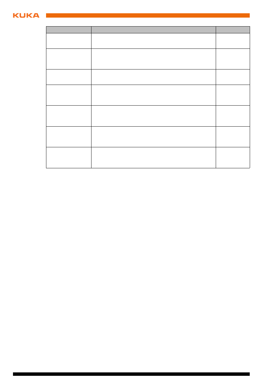
Overview of operating modes and safety functions
The following table indicates the operating modes in which the safety functions
are active.
2.8
Safety measures
2.8.1
General safety measures
The industrial robot may only be used in perfect technical condition in accor-
dance with its intended use and only by safety-conscious persons. Operator
errors can result in personal injury and damage to property.
It is important to be prepared for possible movements of the industrial robot
even after the robot controller has been switched off and locked. Incorrect in-
stallation (e.g. overload) or mechanical defects (e.g. brake defect) can cause
the manipulator or external axes to sag. If work is to be carried out on a
switched-off industrial robot, the manipulator and external axes must first be
moved into a position in which they are unable to move on their own, whether
the payload is mounted or not. If this is not possible, the manipulator and ex-
ternal axes must be secured by appropriate means.
KCP
The user must ensure that the industrial robot is only operated with the KCP
by authorized persons.
If more than one KCP is used in the overall system, it must be ensured that
each KCP is unambiguously assigned to the corresponding industrial robot.
They must not be interchanged.
Safety functions
T1
T2
AUT
AUT EXT
Operator safety
-
-
active
active
EMERGENCY STOP device
active
active
active
active
Enabling device
active
active
-
-
Reduced velocity during pro-
gram verification
active
-
-
-
Jog mode
active
active
-
-
Software limit switches
active
active
active
active
In the absence of operational safety functions and safe-
guards, the industrial robot can cause personal injury or
material damage. If safety functions or safeguards are dismantled or deacti-
vated, the industrial robot may not be operated.
Standing underneath the robot arm can cause death or
serious injuries. For this reason, standing underneath the
robot arm is prohibited!
The motors reach temperatures during operation which
can cause burns to the skin. Contact must be avoided.
Appropriate safety precautions must be taken, e.g. protective gloves must be
worn.

22 / 33
Issued: 21.06.2012 Version: Sicherheit KR C4 V7 en (PDF)
Faults
The following tasks must be carried out in the case of faults in the industrial
robot:
Switch off the robot controller and secure it (e.g. with a padlock) to prevent
unauthorized persons from switching it on again.
Indicate the fault by means of a label with a corresponding warning (tag-
out).
Keep a record of the faults.
Eliminate the fault and carry out a function test.
Modifications
After modifications to the industrial robot, checks must be carried out to ensure
the required safety level. The valid national or regional work safety regulations
must be observed for this check. The correct functioning of all safety circuits
must also be tested.
New or modified programs must always be tested first in Manual Reduced Ve-
locity mode (T1).
After modifications to the industrial robot, existing programs must always be
tested first in Manual Reduced Velocity mode (T1). This applies to all compo-
nents of the industrial robot and includes modifications to the software and
configuration settings.
2.8.2
Transportation
Manipulator
The prescribed transport position of the manipulator must be observed. Trans-
portation must be carried out in accordance with the operating instructions or
assembly instructions of the manipulator.
Robot controller
The robot controller must be transported and installed in an upright position.
Avoid vibrations and impacts during transportation in order to prevent damage
to the robot controller.
Transportation must be carried out in accordance with the operating instruc-
tions or assembly instructions of the robot controller.
External axis
(optional)
The prescribed transport position of the external axis (e.g. KUKA linear unit,
turn-tilt table, etc.) must be observed. Transportation must be carried out in ac-
cordance with the operating instructions or assembly instructions of the exter-
nal axis.
2.8.3
Start-up and recommissioning
Before starting up systems and devices for the first time, a check must be car-
ried out to ensure that the systems and devices are complete and operational,
that they can be operated safely and that any damage is detected.
The valid national or regional work safety regulations must be observed for this
check. The correct functioning of all safety circuits must also be tested.
The operator must ensure that decoupled KCPs are im-
mediately removed from the system and stored out of
sight and reach of personnel working on the industrial robot. This serves to
prevent operational and non-operational EMERGENCY STOP devices from
becoming interchanged.
Failure to observe this precaution may result in death, severe injuries or con-
siderable damage to property.
Issued: 21.06.2012 Version: Sicherheit KR C4 V7 en (PDF)
2 Safety
Function test
The following tests must be carried out before start-up and recommissioning:
General test:
It must be ensured that:
The industrial robot is correctly installed and fastened in accordance with
the specifications in the documentation.
There are no foreign bodies or loose parts on the industrial robot.
All required safety equipment is correctly installed and operational.
The power supply ratings of the industrial robot correspond to the local
supply voltage and mains type.
The ground conductor and the equipotential bonding cable are sufficiently
rated and correctly connected.
The connecting cables are correctly connected and the connectors are
locked.
Test of the safety functions:
A function test must be carried out for the following safety functions to ensure
that they are functioning correctly:
Local EMERGENCY STOP device
External EMERGENCY STOP device (input and output)
Enabling device (in the test modes)
Operator safety
All other safety-relevant inputs and outputs used
Other external safety functions
Test of reduced velocity control:
This test is to be carried out as follows:
1. Program a straight path with the maximum possible velocity.
2. Calculate the length of the path.
3. Execute the path in T1 mode with the override set to 100% and time the
motion with a stopwatch.
The passwords for logging onto the KUKA System Software as “Ex-
pert” and “Administrator” must be changed before start-up and must
only be communicated to authorized personnel.
The robot controller is preconfigured for the specific in-
dustrial robot. If cables are interchanged, the manipula-
tor and the external axes (optional) may receive incorrect data and can thus
cause personal injury or material damage. If a system consists of more than
one manipulator, always connect the connecting cables to the manipulators
and their corresponding robot controllers.
If additional components (e.g. cables), which are not part of the scope
of supply of KUKA Roboter GmbH, are integrated into the industrial
robot, the user is responsible for ensuring that these components do
not adversely affect or disable safety functions.
If the internal cabinet temperature of the robot controller
differs greatly from the ambient temperature, condensa-
tion can form, which may cause damage to the electrical components. Do not
put the robot controller into operation until the internal temperature of the
cabinet has adjusted to the ambient temperature.
24 / 33
Issued: 21.06.2012 Version: Sicherheit KR C4 V7 en (PDF)
4. Calculate the velocity from the length of the path and the time measured
for execution of the motion.
Control of reduced velocity is functioning correctly if the following results are
achieved:
The calculated velocity does not exceed 250 mm/s.
The manipulator executes the path as programmed (i.e. in a straight line,
without deviations).
Machine data
It must be ensured that the rating plate on the robot controller has the same
machine data as those entered in the declaration of incorporation. The ma-
chine data on the rating plate of the manipulator and the external axes (option-
al) must be entered during start-up.
Following modifications to the machine data, the safety configuration must be
checked.
Following modifications to the machine data, control of the reduced velocity
must be checked.
2.8.3.1
Start-up mode
Description
The industrial robot can be set to Start-up mode via the smartHMI user inter-
face. In this mode, the manipulator can be moved in T1 or CRR mode in the
absence of the safety periphery. (CRR is an operating mode specifically for
use with SafeOperation.)
If the X11 interface is used:
Start-up mode is always possible if all input signals have the state “logic
zero”. If this is not the case, the robot controller prevents or terminates
Start-up mode.
If the PROFIsafe interface is used:
If a connection to a higher-level safety system exists or is established, the
robot controller prevents or terminates Start-up mode.
Hazards
Possible hazards and risks involved in using Start-up mode:
A person walks into the manipulator’s danger zone.
An unauthorized person moves the manipulator.
In a hazardous situation, a disabled external EMERGENCY STOP device
is actuated and the manipulator is not shut down.
Additional measures for avoiding risks in Start-up mode:
Cover disabled EMERGENCY STOP devices or attach a warning sign in-
dicating that the EMERGENCY STOP device is out of operation.
It must be ensured that no persons are present within the
danger zone during path execution. Death or severe in-
juries may result.
The industrial robot must not be moved if incorrect ma-
chine data are loaded. Death, severe injuries or consid-
erable damage to property may otherwise result. The correct machine data
must be loaded.
Further information is contained in the Operating and Programming
Instructions for System Integrators.
Issued: 21.06.2012 Version: Sicherheit KR C4 V7 en (PDF)
2 Safety
If there is no safety fence, other measures must be taken to prevent per-
sons from entering the manipulator’s danger zone, e.g. use of warning
tape.
Use of Start-up mode must be minimized – and avoided where possible –
by means of organizational measures.
Use
Intended use of Start-up mode:
Only service personnel who have received safety instruction may use
Start-up mode.
Start-up in T1 mode or CRR mode when the external safeguards have not
yet been installed or put into operation. The danger zone must be delimit-
ed at least by means of warning tape.
Fault localization (periphery fault).
Misuse
Any use or application deviating from the designated use is deemed to be im-
permissible misuse. This includes, for example, use by any other personnel.
KUKA Roboter GmbH accepts no liability for damage or injury caused thereby.
The risk lies entirely with the user.
2.8.4
Manual mode
Manual mode is the mode for setup work. Setup work is all the tasks that have
to be carried out on the industrial robot to enable automatic operation. Setup
work includes:
Jog mode
Teach
Programming
Program verification
The following must be taken into consideration in manual mode:
If the drives are not required, they must be switched off to prevent the ma-
nipulator or the external axes (optional) from being moved unintentionally.
New or modified programs must always be tested first in Manual Reduced
Velocity mode (T1).
The manipulator, tooling or external axes (optional) must never touch or
project beyond the safety fence.
Workpieces, tooling and other objects must not become jammed as a re-
sult of the industrial robot motion, nor must they lead to short-circuits or be
liable to fall off.
All setup work must be carried out, where possible, from outside the safe-
guarded area.
If the setup work has to be carried out inside the safeguarded area, the follow-
ing must be taken into consideration:
Use of Start-up mode disables all external safeguards.
The service personnel are responsible for ensuring that
there is no-one in or near the danger zone of the manipulator as long as the
safeguards are disabled.
Failure to observe this may result in death to persons, injuries or damage to
property.

26 / 33
Issued: 21.06.2012 Version: Sicherheit KR C4 V7 en (PDF)
In Manual Reduced Velocity mode (T1):
If it can be avoided, there must be no other persons inside the safeguard-
ed area.
If it is necessary for there to be several persons inside the safeguarded ar-
ea, the following must be observed:
Each person must have an enabling device.
All persons must have an unimpeded view of the industrial robot.
Eye-contact between all persons must be possible at all times.
The operator must be so positioned that he can see into the danger area
and get out of harm’s way.
In Manual High Velocity mode (T2):
This mode may only be used if the application requires a test at a velocity
higher than Manual Reduced Velocity.
Teaching and programming are not permissible in this operating mode.
Before commencing the test, the operator must ensure that the enabling
devices are operational.
The operator must be positioned outside the danger zone.
There must be no other persons inside the safeguarded area. It is the re-
sponsibility of the operator to ensure this.
2.8.5
Simulation
Simulation programs do not correspond exactly to reality. Robot programs cre-
ated in simulation programs must be tested in the system in Manual Reduced
Velocity mode (T1)
. It may be necessary to modify the program.
2.8.6
Automatic mode
Automatic mode is only permissible in compliance with the following safety
measures:
All safety equipment and safeguards are present and operational.
There are no persons in the system.
The defined working procedures are adhered to.
If the manipulator or an external axis (optional) comes to a standstill for no ap-
parent reason, the danger zone must not be entered until an EMERGENCY
STOP has been triggered.
2.8.7
Maintenance and repair
After maintenance and repair work, checks must be carried out to ensure the
required safety level. The valid national or regional work safety regulations
must be observed for this check. The correct functioning of all safety circuits
must also be tested.
The purpose of maintenance and repair work is to ensure that the system is
kept operational or, in the event of a fault, to return the system to an operation-
al state. Repair work includes troubleshooting in addition to the actual repair
itself.
The following safety measures must be carried out when working on the indus-
trial robot:
Carry out work outside the danger zone. If work inside the danger zone is
necessary, the user must define additional safety measures to ensure the
safe protection of personnel.
Issued: 21.06.2012 Version: Sicherheit KR C4 V7 en (PDF)
2 Safety
Switch off the industrial robot and secure it (e.g. with a padlock) to prevent
it from being switched on again. If it is necessary to carry out work with the
robot controller switched on, the user must define additional safety mea-
sures to ensure the safe protection of personnel.
If it is necessary to carry out work with the robot controller switched on, this
may only be done in operating mode T1.
Label the system with a sign indicating that work is in progress. This sign
must remain in place, even during temporary interruptions to the work.
The EMERGENCY STOP systems must remain active. If safety functions
or safeguards are deactivated during maintenance or repair work, they
must be reactivated immediately after the work is completed.
Faulty components must be replaced using new components with the same
article numbers or equivalent components approved by KUKA Roboter GmbH
for this purpose.
Cleaning and preventive maintenance work is to be carried out in accordance
with the operating instructions.
Robot controller
Even when the robot controller is switched off, parts connected to peripheral
devices may still carry voltage. The external power sources must therefore be
switched off if work is to be carried out on the robot controller.
The ESD regulations must be adhered to when working on components in the
robot controller.
Voltages in excess of 50 V (up to 780 V) can be present in various components
for several minutes after the robot controller has been switched off! To prevent
life-threatening injuries, no work may be carried out on the industrial robot in
this time.
Water and dust must be prevented from entering the robot controller.
Counterbal-
ancing system
Some robot variants are equipped with a hydropneumatic, spring or gas cylin-
der counterbalancing system.
The hydropneumatic and gas cylinder counterbalancing systems are pressure
equipment and, as such, are subject to obligatory equipment monitoring. De-
pending on the robot variant, the counterbalancing systems correspond to cat-
egory 0, II or III, fluid group 2, of the Pressure Equipment Directive.
The user must comply with the applicable national laws, regulations and stan-
dards pertaining to pressure equipment.
Inspection intervals in Germany in accordance with Industrial Safety Order,
Sections 14 and 15. Inspection by the user before commissioning at the instal-
lation site.
The following safety measures must be carried out when working on the coun-
terbalancing system:
The manipulator assemblies supported by the counterbalancing systems
must be secured.
Work on the counterbalancing systems must only be carried out by quali-
fied personnel.
Before work is commenced on live parts of the robot sys-
tem, the main switch must be turned off and secured
against being switched on again. The system must then be checked to en-
sure that it is deenergized.
It is not sufficient, before commencing work on live parts, to execute an
EMERGENCY STOP or a safety stop, or to switch off the drives, as this does
not disconnect the robot system from the mains power supply in the case of
the drives of the new generation. Parts remain energized. Death or severe
injuries may result.
28 / 33
Issued: 21.06.2012 Version: Sicherheit KR C4 V7 en (PDF)
Hazardous
substances
The following safety measures must be carried out when handling hazardous
substances:
Avoid prolonged and repeated intensive contact with the skin.
Avoid breathing in oil spray or vapors.
Clean skin and apply skin cream.
2.8.8
Decommissioning, storage and disposal
The industrial robot must be decommissioned, stored and disposed of in ac-
cordance with the applicable national laws, regulations and standards.
2.8.9
Safety measures for “single point of control”
Overview
If certain components in the industrial robot are operated, safety measures
must be taken to ensure complete implementation of the principle of “single
point of control” (SPOC).
Components:
Submit interpreter
PLC
OPC Server
Remote control tools
Tools for configuration of bus systems with online functionality
KUKA.RobotSensorInterface
Since only the system integrator knows the safe states of actuators in the pe-
riphery of the robot controller, it is his task to set these actuators to a safe
state, e.g. in the event of an EMERGENCY STOP.
T1, T2
In the test modes, the components referred to above may only access the in-
dustrial robot if the following signals have the following states:
Submit inter-
preter, PLC
If motions, (e.g. drives or grippers) are controlled with the submit interpreter or
the PLC via the I/O system, and if they are not safeguarded by other means,
then this control will take effect even in T1 and T2 modes or while an EMER-
GENCY STOP is active.
If variables that affect the robot motion (e.g. override) are modified with the
submit interpreter or the PLC, this takes effect even in T1 and T2 modes or
while an EMERGENCY STOP is active.
Safety measures:
In the test modes, the system variable $OV_PRO must not be written to
by the submit interpreter or the PLC.
To ensure safe use of our products, we recommend that our custom-
ers regularly request up-to-date safety data sheets from the manufac-
turers of hazardous substances.
The implementation of additional safety measures may be required.
This must be clarified for each specific application; this is the respon-
sibility of the system integrator, programmer or user of the system.
Signal
State required for SPOC
$USER_SAF
TRUE
$SPOC_MOTION_ENABLE
TRUE
Issued: 21.06.2012 Version: Sicherheit KR C4 V7 en (PDF)
2 Safety
Do not modify safety-relevant signals and variables (e.g. operating mode,
EMERGENCY STOP, safety gate contact) via the submit interpreter or
PLC.
If modifications are nonetheless required, all safety-relevant signals and
variables must be linked in such a way that they cannot be set to a dan-
gerous state by the submit interpreter or PLC.
OPC server,
remote control
tools
These components can be used with write access to modify programs, outputs
or other parameters of the robot controller, without this being noticed by any
persons located inside the system.
Safety measures:
KUKA stipulates that these components are to be used exclusively for di-
agnosis and visualization.
Programs, outputs or other parameters of the robot controller must not be
modified using these components.
If these components are used, outputs that could cause a hazard must be
determined in a risk assessment. These outputs must be designed in such
a way that they cannot be set without being enabled. This can be done us-
ing an external enabling device, for example.
Tools for configu-
ration of bus
systems
If these components have an online functionality, they can be used with write
access to modify programs, outputs or other parameters of the robot control-
ler, without this being noticed by any persons located inside the system.
WorkVisual from KUKA
Tools from other manufacturers
Safety measures:
In the test modes, programs, outputs or other parameters of the robot con-
troller must not be modified using these components.
2.9
Applied norms and regulations
Name
Definition
Edition
2006/42/EC
Machinery Directive:
Directive 2006/42/EC of the European Parliament and of
the Council of 17 May 2006 on machinery, and amending
Directive 95/16/EC (recast)
2006
2004/108/EC
EMC Directive:
Directive 2004/108/EC of the European Parliament and of
the Council of 15 December 2004 on the approximation of
the laws of the Member States relating to electromagnetic
compatibility and repealing Directive 89/336/EEC
2004
97/23/EC
Pressure Equipment Directive:
Directive 97/23/EC of the European Parliament and of the
Council of 29 May 1997 on the approximation of the laws
of the Member States concerning pressure equipment
(Only applicable for robots with hydropneumatic counter-
balancing system.)
1997
EN ISO 13850
Safety of machinery:
Emergency stop - Principles for design
2008
EN ISO 13849-1
Safety of machinery:
Safety-related parts of control systems - Part 1: General
principles of design
2008
30 / 33
Issued: 21.06.2012 Version: Sicherheit KR C4 V7 en (PDF)
EN ISO 13849-2
Safety of machinery:
Safety-related parts of control systems - Part 2: Validation
2008
EN ISO 12100
Safety of machinery:
General principles of design, risk assessment and risk
reduction
2010
EN ISO 10218-1
Industrial robots:
Safety
2011
EN 614-1
Safety of machinery:
Ergonomic design principles - Part 1: Terms and general
principles
2006
EN 61000-6-2
Electromagnetic compatibility (EMC):
Part 6-2: Generic standards; Immunity for industrial envi-
ronments
2005
EN 61000-6-4
Electromagnetic compatibility (EMC):
Part 6-4: Generic standards; Emission standard for indus-
trial environments
2007
EN 60204-1
Safety of machinery:
Electrical equipment of machines - Part 1: General
requirements
2006
Name
Definition
Edition

31 / 33
Issued: 21.06.2012 Version: Sicherheit KR C4 V7 en (PDF)
Index
Index
Numbers
2004/108/EC 29
2006/42/EC 29
89/336/EEC 29
95/16/EC 29
97/23/EC 29
A
Accessories 7
Applied norms and regulations 29
Automatic mode 26
Axis range 9
Axis range limitation 18
Axis range monitoring 18
B
Brake defect 21
Brake release device 19
Braking distance 9
C
CE mark 8
Cleaning work 27
Connecting cables 7
Counterbalancing system 27
D
Danger zone 9
Declaration of conformity 8
Declaration of incorporation 7, 8
Decommissioning 28
Disposal 28
E
EC declaration of conformity 8
EMC Directive 8, 29
EMERGENCY STOP device 15, 16, 21
EMERGENCY STOP, external 16, 23
EMERGENCY STOP, local 23
EN 60204-1 30
EN 61000-6-2 30
EN 61000-6-4 30
EN 614-1 30
EN ISO 10218-1 30
EN ISO 12100 30
EN ISO 13849-1 29
EN ISO 13849-2 30
EN ISO 13850 29
Enabling device 16, 21
Enabling device, external 17
Enabling switches 16
External axes 7, 10
G
General safety measures 21
Guard interlock 14
I
Industrial robot 7
Intended use 7
Introduction 5
L
Labeling 20
Liability 7
Linear unit 7
Low Voltage Directive 8
M
Machine data 24
Machinery Directive 8, 29
Maintenance 26
Manipulator 7, 9, 12
Manual mode 25
Mechanical axis range limitation 18
Mechanical end stops 18
Mode selection 13, 14
Monitoring, velocity 17
O
Operator 9, 11
Operator safety 13, 14, 21
Options 7
Overload 21
P
Panic position 16
Performance Level 13
Personnel 10
Plant integrator 10
Positioner 7
Pressure Equipment Directive 27, 29
Preventive maintenance work 27
Protective equipment 17
R
Reaction distance 9
Recommissioning 22
Release device 19
Repair 26
Robot controller 7

32 / 33
Issued: 21.06.2012 Version: Sicherheit KR C4 V7 en (PDF)
S
Safe operational stop 9, 17
Safeguards, external 20
Safety 7
Safety controller 14
Safety functions 21
Safety functions, overview 13
Safety instructions 5
Safety STOP 0 9
Safety STOP 1 9
Safety STOP 2 10
Safety STOP 0 9
Safety STOP 1 9
Safety STOP 2 10
Safety stop, external 17
Safety zone 9, 11, 12
Safety, general 7
Service life 9
Simulation 26
Single point of control 28
smartPAD 9
Software 7
Software limit switches 17, 21
SPOC 28
Start-up 22
Start-up mode 24
STOP 0 8, 10
STOP 1 8, 10
STOP 2 8, 10
Stop category 0 10
Stop category 1 10
Stop category 2 10
Stop reactions 12
Stopping distance 9, 12
Storage 28
System integrator 8, 10, 11
T
T1 10
T2 10
Teach pendant 7
Terms used, safety 8
Transport position 22
Transportation 22
Turn-tilt table 7

Document Outline
- Industrial Robots, Safety
- 1 Introduction
- 2 Safety
- 2.1 General
- 2.2 Personnel
- 2.3 Workspace, safety zone and danger zone
- 2.4 Triggers for stop reactions
- 2.5 Safety functions
- 2.5.1 Overview of the safety functions
- 2.5.2 Safety controller
- 2.5.3 Mode selection
- 2.5.4 Operator safety
- 2.5.5 EMERGENCY STOP device
- 2.5.6 Logging off the higher-level safety controller
- 2.5.7 External EMERGENCY STOP device
- 2.5.8 Enabling device
- 2.5.9 External enabling device
- 2.5.10 External safe operational stop
- 2.5.11 External safety stop 1 and external safety stop 2
- 2.5.12 Velocity monitoring in T1
- 2.6 Additional protective equipment
- 2.6.1 Jog mode
- 2.6.2 Software limit switches
- 2.6.3 Mechanical end stops
- 2.6.4 Mechanical axis range limitation (optional)
- 2.6.5 Axis range monitoring (optional)
- 2.6.6 Devices for moving the manipulator without the robot controller (options)
- 2.6.7 Labeling on the industrial robot
- 2.6.8 External safeguards
- 2.7 Overview of operating modes and safety functions
- 2.8 Safety measures
- 2.9 Applied norms and regulations
- Index
Wyszukiwarka
Podobne podstrony:
KR C4 PROFIBUS KSS VSS 83 en
KR C4 Quick Start Pierwsze kroki v4
kb safety en
KR C2 ed05 Battery Monitoring en
krc2 ed05 safetybus en
BA KR C2 ed05 Main Switch with Cover en
so c4
new employee safety orientation 1201643571904060 5
Kręgowce
Przedmiot dzialy i zadania kryminologii oraz metody badan kr
Safety net
Fizyka j c4 85drowa
Budzik Versa wielkość karty kredytowej instrukcja EN
G2 4 PW EN wn Rys 01
Kr 029 Zieby Darwina umozliwiaja stestowanie rywalizujacych koncepcji pochodzenia
Laboratorium jezyk c4 2013
Manual Acer TravelMate 2430 US EN
więcej podobnych podstron