KRC2ed05 SafetyBus mit E/A 11.05.00 en
CONTROL CABINET
KR C2 edition2005
Interface, SafetyBUS with I/Os
Option 00--137--610
Customer Documentation
Issued: 09 Jan 2006
Version: 00

KRC2ed05 SafetyBus mit E/A 11.05.00 en
e
Copyright
2005
KUKA Roboter GmbH
Zugspitzstrasse 140
D--86165 Augsburg
This documentation or excerpts therefrom may not be reproduced or disclosed to third parties without the express permission of the
publishers.
Other functions not described in this documentation may be operable in the controller. The user has no claims to these functions,
however, in the case of a replacement or service work.
We have checked the content of this documentation for conformity with the hardware and software described. Nevertheless,
discrepancies cannot be precluded, for which reason we are not able to guarantee total conformity. The information in this
documentation is checked on a regular basis, however, and necessary corrections will be incorporated in subsequent editions.
Subject to technical alterations without an effect on the function.

3 of 26
KRC2ed05 SafetyBus mit E/A 11.05.00 en
Contents
1
Introduction
5
. . . . . . . . . . . . . . . . . . . . . . . . . . . . . . . . . . . . . . . . . . . . . . . . .
1.1
Use
5
. . . . . . . . . . . . . . . . . . . . . . . . . . . . . . . . . . . . . . . . . . . . . . . . . . . . . . . . . . . . . . . . . . . . . . . . . .
1.2
Configuration
6
. . . . . . . . . . . . . . . . . . . . . . . . . . . . . . . . . . . . . . . . . . . . . . . . . . . . . . . . . . . . . . . . . .
2
Safety
7
. . . . . . . . . . . . . . . . . . . . . . . . . . . . . . . . . . . . . . . . . . . . . . . . . . . . . .
2.1
Fundamentals
7
. . . . . . . . . . . . . . . . . . . . . . . . . . . . . . . . . . . . . . . . . . . . . . . . . . . . . . . . . . . . . . . . .
2.2
Additional safety instructions, “SafetyBUS with I/Os”
7
. . . . . . . . . . . . . . . . . . . . . . . . . . . . . . . .
2.3
Liability
8
. . . . . . . . . . . . . . . . . . . . . . . . . . . . . . . . . . . . . . . . . . . . . . . . . . . . . . . . . . . . . . . . . . . . . . .
2.4
Designated use
8
. . . . . . . . . . . . . . . . . . . . . . . . . . . . . . . . . . . . . . . . . . . . . . . . . . . . . . . . . . . . . . . .
3
Product description
9
. . . . . . . . . . . . . . . . . . . . . . . . . . . . . . . . . . . . . . . . .
3.1
Control cabinet, overview
9
. . . . . . . . . . . . . . . . . . . . . . . . . . . . . . . . . . . . . . . . . . . . . . . . . . . . . . .
3.2
Connection panel
10
. . . . . . . . . . . . . . . . . . . . . . . . . . . . . . . . . . . . . . . . . . . . . . . . . . . . . . . . . . . . . .
3.2.1
Safety
10
. . . . . . . . . . . . . . . . . . . . . . . . . . . . . . . . . . . . . . . . . . . . . . . . . . . . . . . . . . . . . . . . . . . . . . . .
3.2.2
Overview
10
. . . . . . . . . . . . . . . . . . . . . . . . . . . . . . . . . . . . . . . . . . . . . . . . . . . . . . . . . . . . . . . . . . . . .
3.3
SafetyBUS Gateway A
11
. . . . . . . . . . . . . . . . . . . . . . . . . . . . . . . . . . . . . . . . . . . . . . . . . . . . . . . . .
4
Power supply for ESC and SafetyBUS Gateway A
12
. . . . . . . . . . . . . .
4.1
Internal power supply via X111
12
. . . . . . . . . . . . . . . . . . . . . . . . . . . . . . . . . . . . . . . . . . . . . . . . . . .
4.2
External power supply via X111
13
. . . . . . . . . . . . . . . . . . . . . . . . . . . . . . . . . . . . . . . . . . . . . . . . . .
4.3
External power supply via X111a in interlinked systems
14
. . . . . . . . . . . . . . . . . . . . . . . . . . . . .
5
Start--up function
16
. . . . . . . . . . . . . . . . . . . . . . . . . . . . . . . . . . . . . . . . . . . .
6
Safeguard in system operation
17
. . . . . . . . . . . . . . . . . . . . . . . . . . . . . . .
6.1
Error message via SafetyBUS
17
. . . . . . . . . . . . . . . . . . . . . . . . . . . . . . . . . . . . . . . . . . . . . . . . . . .
6.2
Error message via ESC
18
. . . . . . . . . . . . . . . . . . . . . . . . . . . . . . . . . . . . . . . . . . . . . . . . . . . . . . . . .
7
Connector pin allocation
19
. . . . . . . . . . . . . . . . . . . . . . . . . . . . . . . . . . . . .
7.1
Peripheral connector X111
19
. . . . . . . . . . . . . . . . . . . . . . . . . . . . . . . . . . . . . . . . . . . . . . . . . . . . . .
7.2
SafetyBUS X111a IN and X111b OUT
22
. . . . . . . . . . . . . . . . . . . . . . . . . . . . . . . . . . . . . . . . . . . . .
7.3
Service jumper plug for X111 -- KR C2 edition2005
23
. . . . . . . . . . . . . . . . . . . . . . . . . . . . . . . . .
8
Interface signals
24
. . . . . . . . . . . . . . . . . . . . . . . . . . . . . . . . . . . . . . . . . . . .
8.1
Interface X111
24
. . . . . . . . . . . . . . . . . . . . . . . . . . . . . . . . . . . . . . . . . . . . . . . . . . . . . . . . . . . . . . . . .
8.2
Interface X111a IN
26
. . . . . . . . . . . . . . . . . . . . . . . . . . . . . . . . . . . . . . . . . . . . . . . . . . . . . . . . . . . . .
8.3
Interface X111b OUT
26
. . . . . . . . . . . . . . . . . . . . . . . . . . . . . . . . . . . . . . . . . . . . . . . . . . . . . . . . . . .

Interface, SafetyBUS with I/Os
4 of 26
KRC2ed05 SafetyBus mit E/A 11.05.00 en

1
Introduction
5 of 26
KRC2ed05 SafetyBus mit E/A 11.05.00 en
1
Introduction
The option “KR C2 edition2005 Interface, SafetyBUS with I/Os” makes it possible
to connect user--specific input and output signals to the KR C2 edition2005 control
cabinet.
The CI3 bus board is used. On this board an additional bus coupler SafetyBUS
Gateway A is mounted. Depending on the interface design, a CI3 Tech board can
also be used.
1.1
Use
The bus coupler SafetyBUS Gateway A makes 8 safe inputs and 2 safe outputs
available at the interface connector X111. 2 further safe outputs each control 2
contactors, K11/K12 and K13/K14, from which each has 1 floating contact routed
to the interface. This bus coupler is connected to the ESC. The external 24 V DC
power supply for the ESC and the SafetyBUS connection is supplied via connector
X111a, and the outgoing connection is made at connector X111b. Thus additional
ESC and SafetyBUS connections of subsequent control cabinets can be supplied
with this voltage. It is also possible to supply this external voltage via connector
X111.
The option “KR C2 edition2005 Interface, SafetyBUS with I/Os” provides the
following functions:
G
SafetyBUS Gateway connection
G
8 safe inputs via SafetyBUS Gateway
G
2 safe outputs via SafetyBUS Gateway
G
2 safe outputs for contactor control
G
ESC and SafetyBUS power supply
S
External power supply
S
Internal power supply
S
Linking of several control cabinets

Interface, SafetyBUS with I/Os
6 of 26
KRC2ed05 SafetyBus mit E/A 11.05.00 en
1.2
Configuration
The basic cabinet is the KR C2 edition2005. Therefore this documentation only
describes the differences from the standard cabinet.
The following hardware components are included in the option “KR C2 edition2005
Interface, SafetyBUS with I/Os”:
G
C13 bus board or C13 Tech board
G
SafetyBUS Gateway A
G
Peripheral connector X111
G
SafetyBUS connectors X111a and X111b
G
Contactors K11 -- K14
G
Terminal block X2.2

2
Safety
7 of 26
KRC2ed05 SafetyBus mit E/A 11.05.00 en
2
Safety
2.1
Fundamentals
Warning!
Failure to observe these safety instructions could result in injury or a fatal
accident and/or damage to the robot system or other property!
G
All pertinent safety regulations as well as the booklet [Safety and Installation
Instructions] are to be observed when working on the system.
G
The KUKA safety chapter [KRC Safety, General] is supplied with the robot
system and must be read and understood before commencing work.
G
The safety instructions in the KR C2 edition2005 Operating Handbook must
be observed.
G
Before connection, testing and installation work, always refer to the
accompanying circuit diagram.
2.2
Additional safety instructions, “SafetyBUS with I/Os”
G
Installation, exchange and service work on this option or individual
components thereof may be performed only by qualified personnel specially
trained for this purpose and acquainted with the risks involved.
G
The max. current load of connectors X111a and X111b is 10 A. Exceeding this
current limit results in overloading and destruction of the connectors.
G
When the start--up function is used, the robot may only be operated in
AUTOMATIC mode if a functioning safeguard is connected!

Interface, SafetyBUS with I/Os
8 of 26
KRC2ed05 SafetyBus mit E/A 11.05.00 en
2.3
Liability
This option is designed and built using state--of--the--art technology and in
accordance with the recognized safety rules. Nevertheless, improper installation
of this option or its employment for a purpose other than the intended one may
constitute a risk to life and limb of operating personnel or of third parties, or cause
damage to or failure of the control cabinet, resulting in damage to or failure of the
entire robot system and other material property.
The option “Interface, SafetyBUS with I/Os” may only be used in technically perfect
condition in accordance with its designated use and only by safety--conscious
persons who are fully aware of the risks involved in its operation. Connection and
use must be carried out in compliance with this documentation.
2.4
Designated use
Using this option for any purpose other than or additional to that described in
Section 1.1 is considered contrary to its designated use. The manufacturer cannot
be held liable for any damage resulting from such use.
The risk lies entirely with the user.
No liability can be accepted if these directions are disregarded.
3
Product description
9 of 26
KRC2ed05 SafetyBus mit E/A 11.05.00 en
3
Product description
3.1
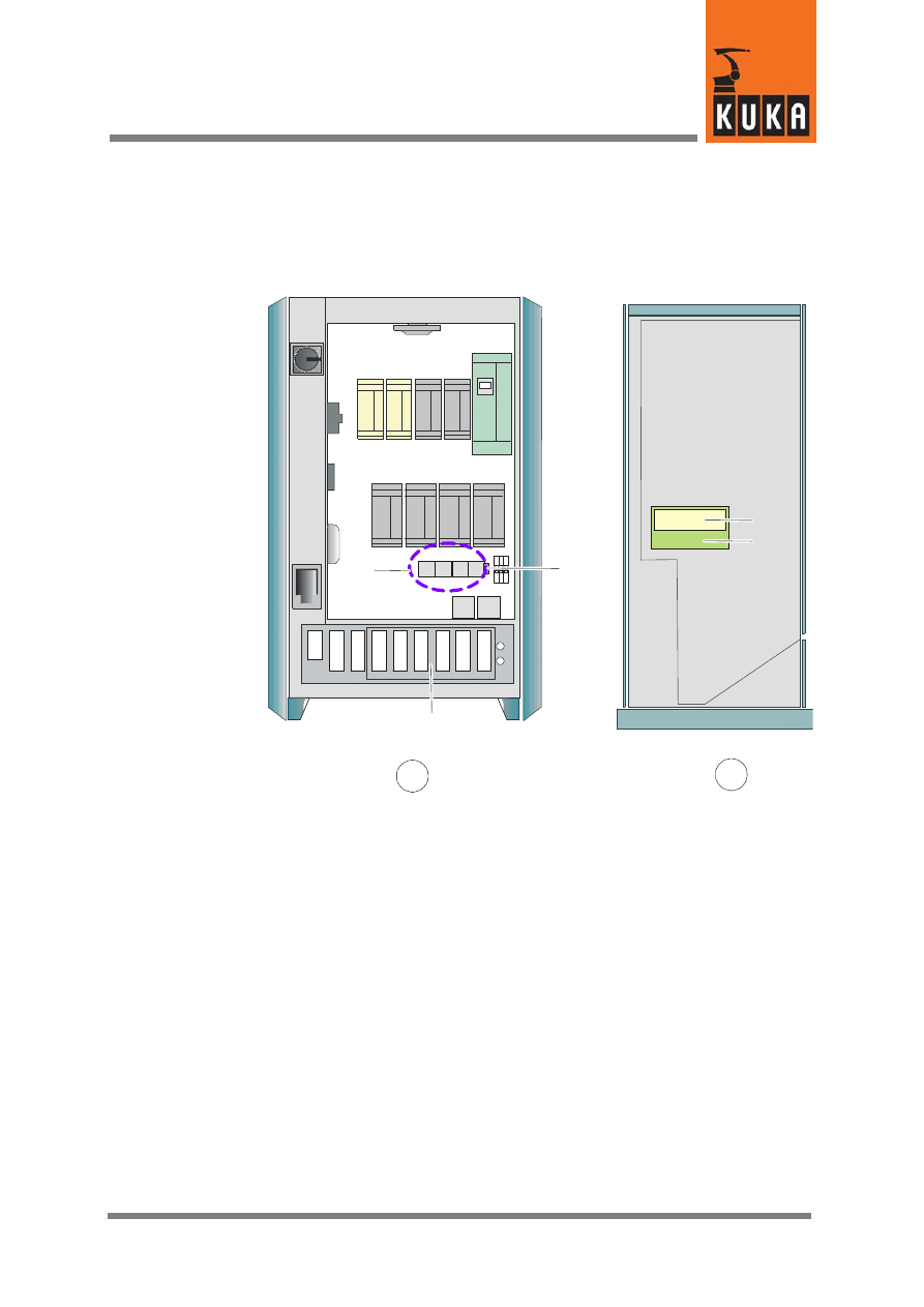
Control cabinet, overview
1
4
A
B
5
2
3
A
Front view
B
Side view, right
1
Connection panel
2
Contactors K11 -- K14
3
Terminal block 2.2
4
Bus coupler SafetyBUS Gateway A
5
Safety module CI3 Bus board
Fig. 1 Control cabinet, overview
Interface, SafetyBUS with I/Os
10 of 26
KRC2ed05 SafetyBus mit E/A 11.05.00 en
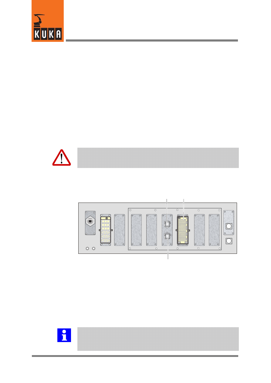
3.2
Connection panel
All the connectors on the connection panel are plug--and--socket connections as
defined by VDE 0627.
Plug--and--socket connections must not be plugged or unplugged while the
controller is operational (i.e. energized).
Requirements:
G
Qualified technical personnel (skilled workers) trained in the handling of
systems and machines.
3.2.1
Safety
Warning!
Before the plug--and--socket connections are plugged or unplugged, the con-
troller and the cables concerned must be deenergized.
3.2.2
Overview
1
2
3
1
X111a SafetyBUS interface IN
2
X111 Peripheral interface
3
X111b SafetyBUS interface OUT
Fig. 2 Connection panel
The installation positions of the connectors may vary from those illustrated here
depending on the cabinet equipment.
Further information
All contactor, relay and valve coils that are connected to the robot controller
by the user must be equipped with suitable suppressor diodes. (RC elements
and VCR resistors are not suitable.)

3
Product description (continued)
11 of 26
KRC2ed05 SafetyBus mit E/A 11.05.00 en
3.3
SafetyBUS Gateway A
Further information
The SafetyBUS Gateway A is described in detail in the documentation “ESC
Safety System with Gateway”.
Interface, SafetyBUS with I/Os
12 of 26
KRC2ed05 SafetyBus mit E/A 11.05.00 en
4
Power supply for ESC and SafetyBUS Gateway A
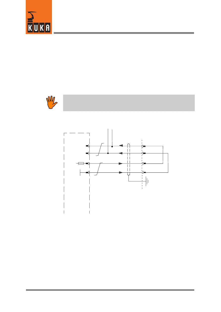
4.1
Internal power supply via X111
The ESC and the SafetyBUS can be supplied with 24 V DC internally via
connector X111, pins 88/89. For this, the jumpers at the interface X111 must be set
in accordance with Fig. 3.
Caution!
In this case, no external power supply may be connected to connector X111a
and no power supply may be routed to other control cabinets via X111b.
X111
88
89
S
afe
ty
modul
e
C
I3
bus
A1
X6
106
107
+24 V internal
0 V internal
7
8
3
4
PE
Via X2.2 to the interfaces
X111a and X111b
4 A
Fig. 3 Internal ESC and SafetyBUS power supply
4
Power supply for ESC and SafetyBUS Gateway A (continued)
13 of 26
KRC2ed05 SafetyBus mit E/A 11.05.00 en
4.2
External power supply via X111
The ESC and the SafetyBUS can be supplied with 24 V DC externally via connector
X111, pins 88/89.
Caution!
In this case, no external power supply may be connected to connector X111a
and no power supply may be routed to other control cabinets via X111b.
X111
24 V external
0 V external
88
89
S
afe
ty
modul
e
C
I3
bus
A1
X6
106
107
+24 V internal
0 V internal
7
8
3
4
PE
Via X2.2 to the interfaces
X111a and X111b
4 A
Fig. 4 External ESC and SafetyBUS power supply

Interface, SafetyBUS with I/Os
14 of 26
KRC2ed05 SafetyBus mit E/A 11.05.00 en
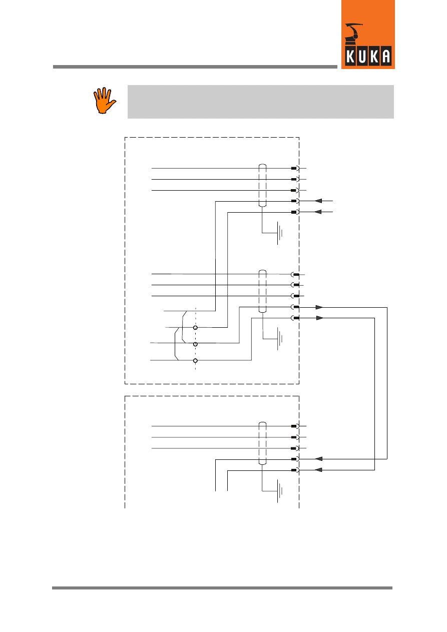
4.3
External power supply via X111a in interlinked systems
The ESC and the SafetyBUS power supply can be applied externally via the
interface connector X111a (Fig. 5). The external power supply then continues in
the control cabinet to the connectors X111b and X111. At connector X111b the
external power supply connection and the SafetyBUS connection to the next
control cabinet can be made.
The number of control cabinets that can be connected in series depends on the
load on the SafetyBUS Gateway A (4 outputs, max. 1 A) and the power consump-
tion of the ESC circuit (max. 1.5 A depending on the number of inputs activated).
Calculation example
Load on output A0:
1.00 A
Load on outputs A1/A2:
0.60 A
(relays K11 -- K14)
Load on output A3:
1.00 A
ESC circuit:
1.50 A
Total current:
4.10 A
In this example, 2 control cabinets can be connected in series.
4
Power supply for ESC and SafetyBUS Gateway A (continued)
15 of 26
KRC2ed05 SafetyBus mit E/A 11.05.00 en
Caution!
The max. current load of connectors X111a and X111b is 10 A. Exceeding this
current limit results in overloading and destruction of the connectors.
X111a IN
1
2
3
1.
CAN GND
CAN L
CAN H
24 V DC external
X111b OUT
1
2
3
1.
CAN GND
CAN L
CAN H
2.
0 V external
2.
X2.2
In
te
rf
ac
e
connec
to
r
X
11
1
X111a IN
1
2
3
1.
CAN GND
CAN L
CAN H
24
V
D
C
ex
ter
nal
2.
0
V
ex
te
rnal
Control cabinet 1
Control cabinet 2
Fig. 5 External power supply in interlinked systems
Interface, SafetyBUS with I/Os
16 of 26
KRC2ed05 SafetyBus mit E/A 11.05.00 en
5
Start--up function
The start--up function makes it possible to activate the safety circuit of the robot
when it is not connected to the SafetyBUS. If a HIGH level (test output A/B) is
detected on the two inputs INB(A) and INB(B) (connector X111, pins 31 und 32),
then the start--up function is activated and the SafetyBUS is ignored. While the
start--up function is activated the digital inputs and outputs of the SafetyBUS
Gateway A will not take effect.
Caution!
When the start--up function is used, the robot may only be operated in AUTO-
MATIC mode if a functioning safeguard is connected!
Further information
In order to be able to operate the robot also in AUTOMATIC mode, two
additional inputs of safeguard channel A (connector X111, pin 13) and of
safeguard channel B (connector X111, pin 14) must detect a HIGH level.
6
Safeguard in system operation
17 of 26
KRC2ed05 SafetyBus mit E/A 11.05.00 en
6
Safeguard in system operation
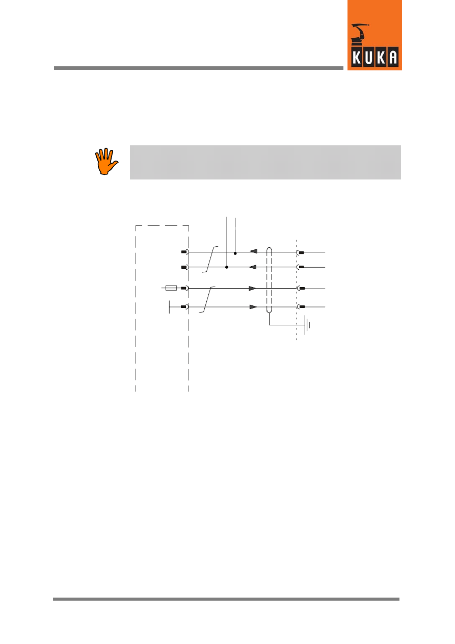
6.1
Error message via SafetyBUS
If the SafetyBUS connection of the KR C2 edition2005 control cabinet signals
operator safety or safeguard via the SafetyBUS, jumpers (pins 13/15 and 14/16)
for the safeguard are required on the X111 interface. If these jumpers are not set,
an operator safety error message is generated via the ESC circuit.
X111
13
Safeguard
Channel A
88
89
S
afe
ty
modul
e
C
I3
bus
A1
X6
X22
106
107
7
8
3
4
9
14
28
15
1
Safeguard
Channel B
Test output A
16
Test output B
20
X 2.2
Interface, SafetyBUS with I/Os
18 of 26
KRC2ed05 SafetyBus mit E/A 11.05.00 en
6.2
Error message via ESC
If operator safety is not signaled via the SafetyBUS, an effective safeguard must
be connected at the terminals X111, pins 13 and 15 and X111, pins 14 and 16.
X111
13
88
89
S
afe
ty
modul
e
C
I3
bus
A1
X6
X22
106
107
7
8
3
4
9
14
28
15
1
S
af
eguar
d
16
20
X 2.2
7
Connector pin allocation
19 of 26
KRC2ed05 SafetyBus mit E/A 11.05.00 en
7
Connector pin allocation
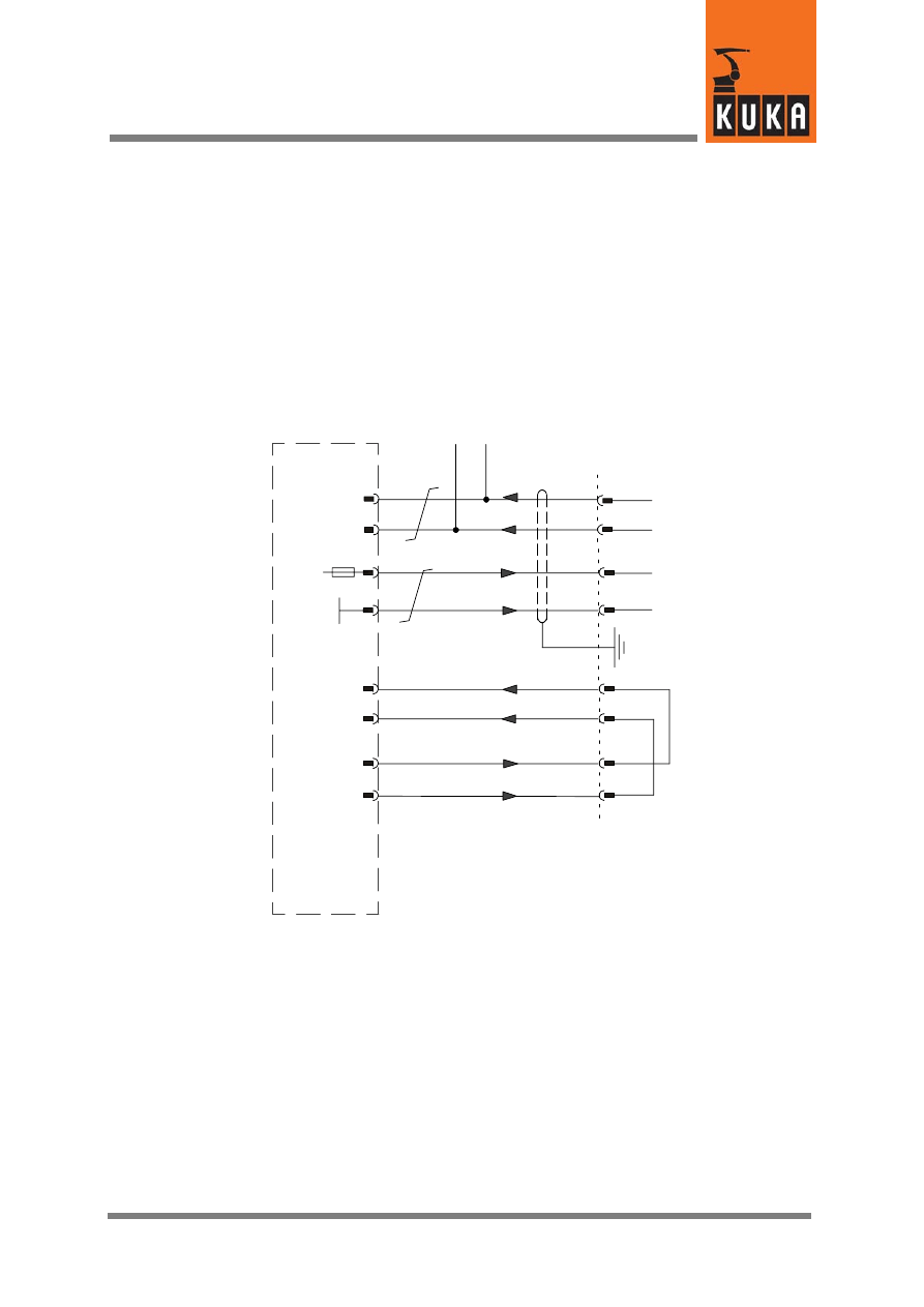
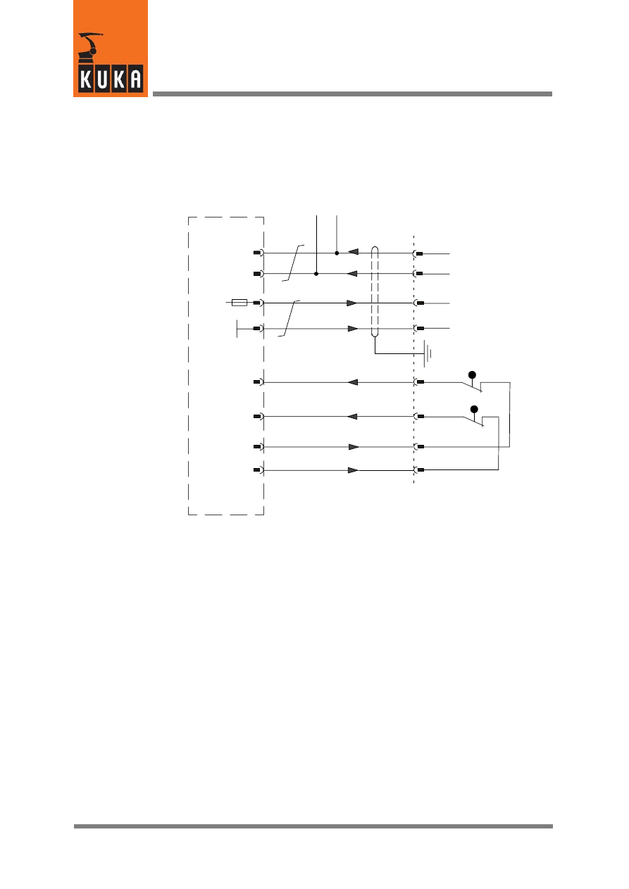
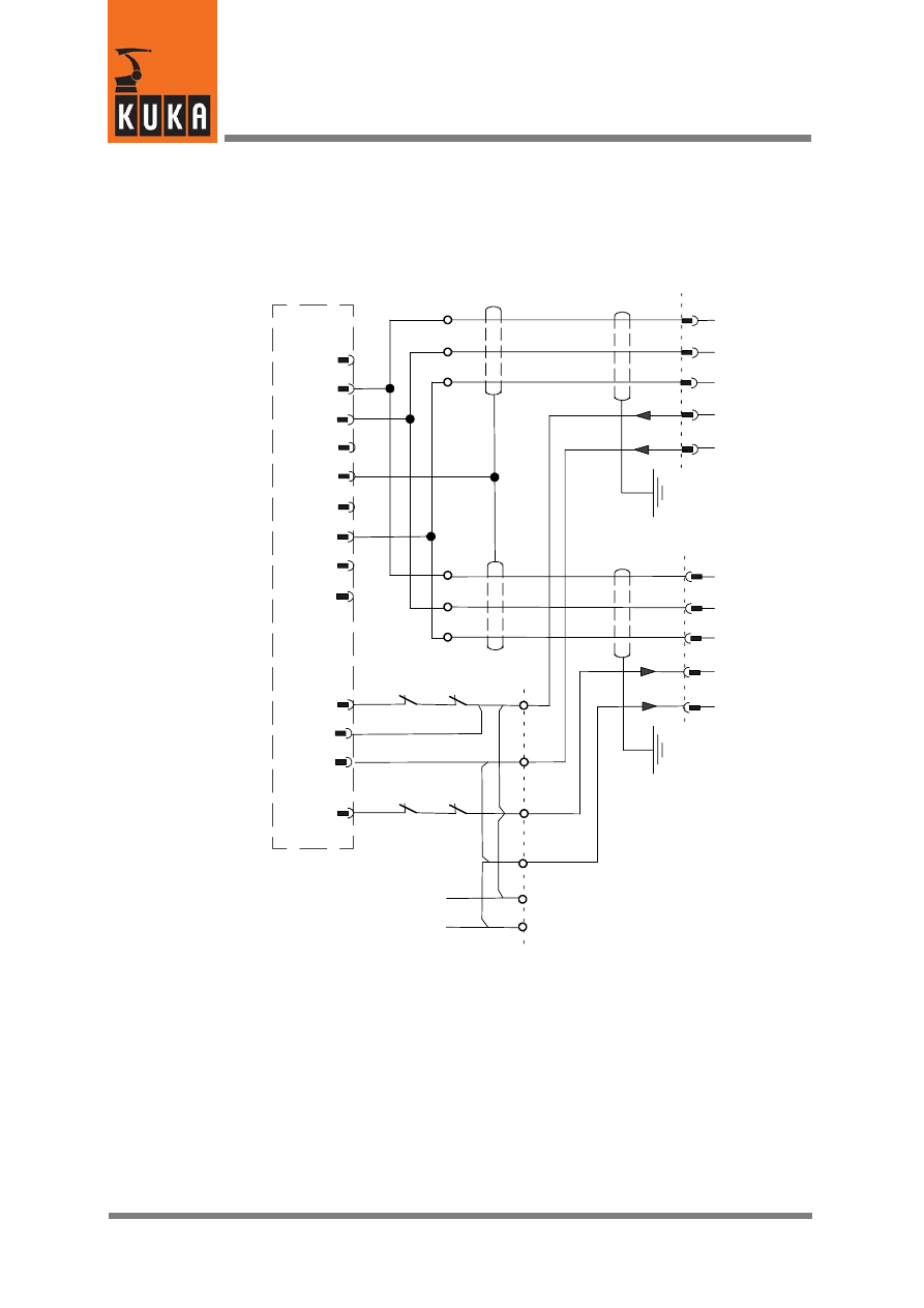
7.1
Peripheral connector X111
X111
24 V external
0 V external
13
Safeguard channel A
88
89
S
afe
ty
modul
e
C
I3
bus
A1
X6
X22
106
107
+24 V internal
0 V internal
7
8
3
4
9
14
28
15
1
Safeguard channel B
Test output A
16
Test output B
20
PE
X 2.2
90
24 V DC control voltage, 6 A
36
24 V DC control voltage, 4 A
72
0 V control voltage
18
0 V control voltage
1
2
3
4
X12
Option
X1
INB (B)
17
32
18
/TA24V (A)
20
34
21
31
33
INB (A)
/TA24V (A)
S
afe
ty
BUS
G
ate
w
ay
A
A1
.1
/TA24V (B)
53
22
/TA24V (B)
54
23
Interface, SafetyBUS with I/Os
20 of 26
KRC2ed05 SafetyBus mit E/A 11.05.00 en
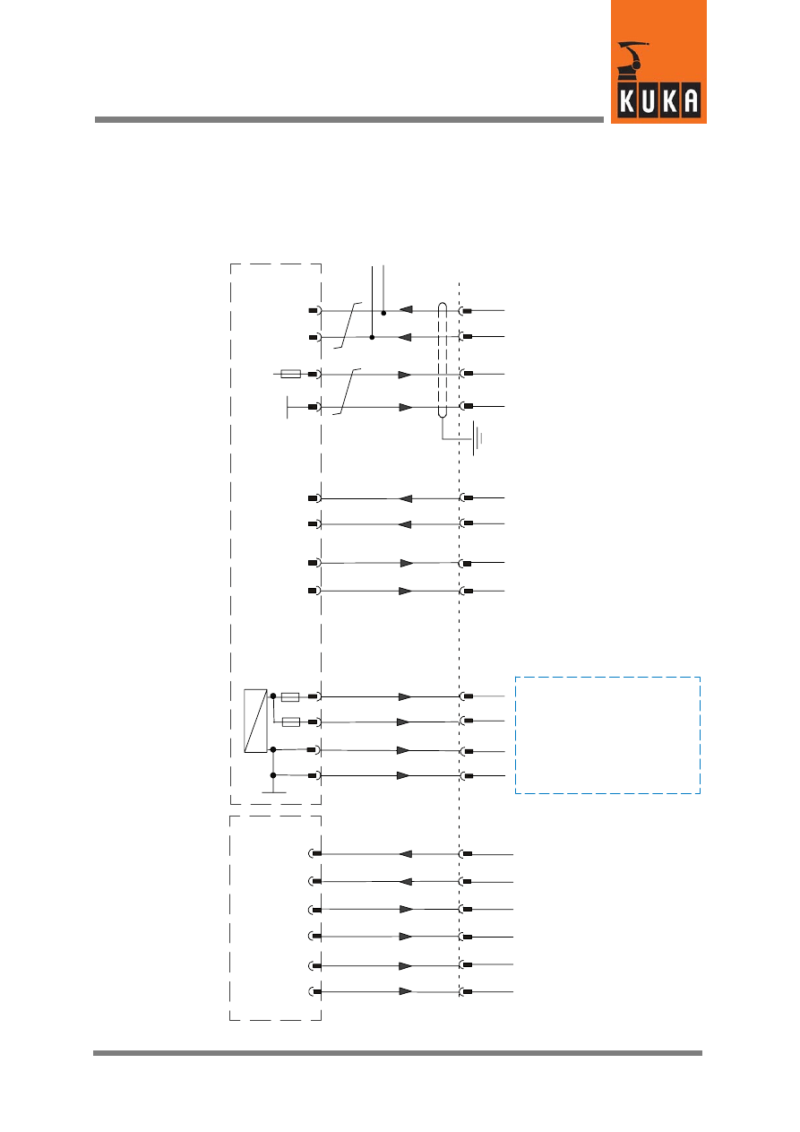
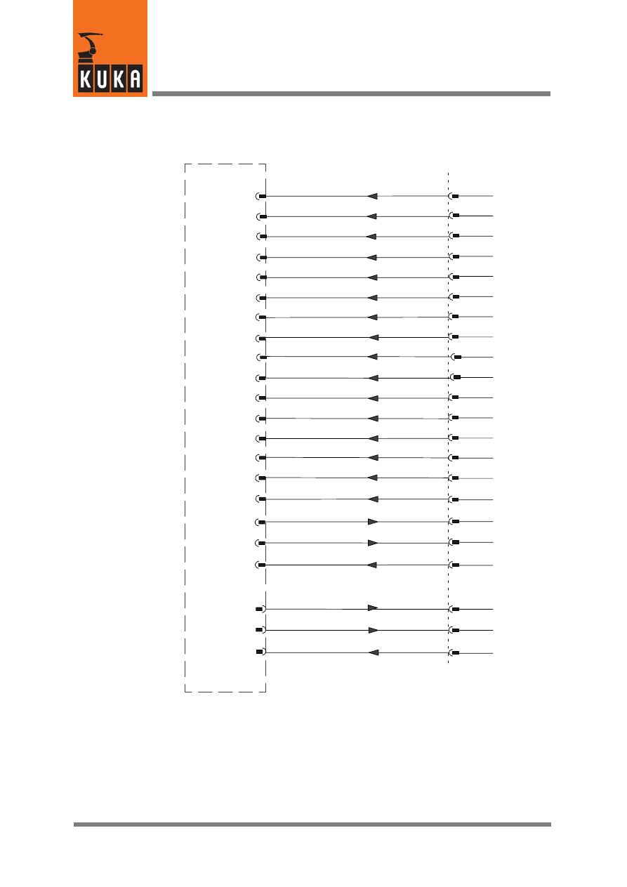
S
afe
ty
modul
e
S
af
et
yBUS
G
ate
w
ay
A
A1
.1
X1
X111
D0 (A)
D3 (B)
38
2
39
3
D0 (B)
D1 (A)
40
D1 (B)
4
41
5
42
6
D2 (A)
D2 (B)
7
44
8
D4 (B)
9
46
10
1
D5 (A)
48
12
49
13
D5 (B)
D6 (A)
50
D6 (B)
14
51
15
52
16
D7 (A)
D7 (B)
11
A0 (B)
28
61
30
RAE2--A0
32
37
43
47
45
60
D3 (A)
D4 (A)
A0 (A)
Peripheral connector X111 (continued)
A3 (B)
1
64
3
RAE2--A3
65
5
63
A3 (A)
X8
62
7
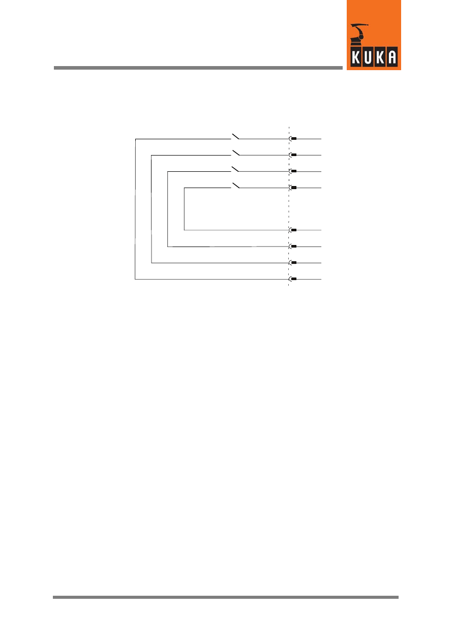
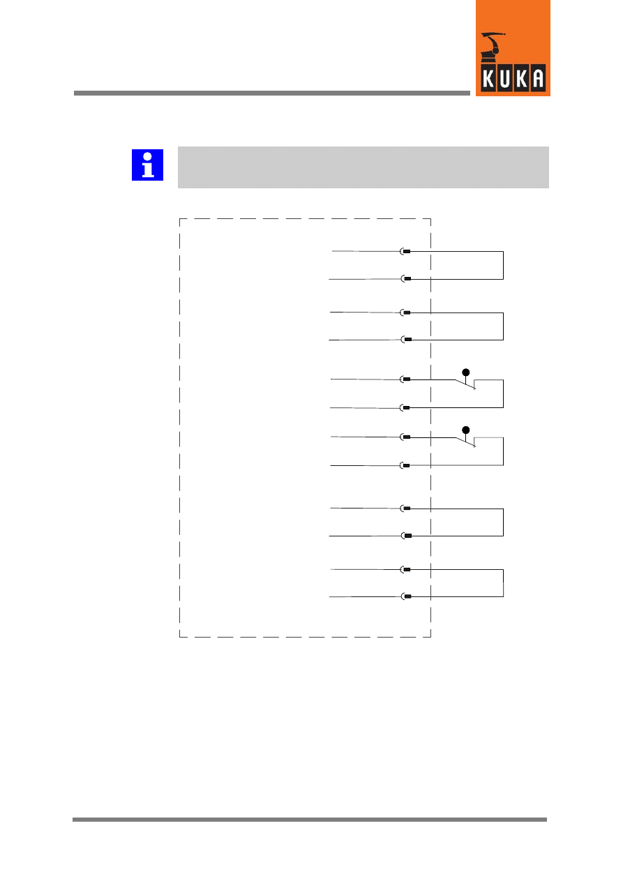
Connector pin allocation (continued)
21 of 26
KRC2ed05 SafetyBus mit E/A 11.05.00 en
X111
Relay contact K14
Relay contact K14
78
76
Relay contact K13
Relay contact K12
74
Relay contact K11
73
75
Relay contact K11
Relay contact K12
79
80
77
Relay contact K13
Peripheral connector X111 (continued)
K14
K13
K12
K11
Interface, SafetyBUS with I/Os
22 of 26
KRC2ed05 SafetyBus mit E/A 11.05.00 en
7.2
SafetyBUS X111a IN and X111b OUT
The max. current value for the X111a or X111b 24 V DC external connection is 10 A.
X111a IN
1
2
3
1.
CAN GND
CAN L
CAN H
24 V DC ext.
Shield
X111b OUT
1
2
3
1.
CAN GND
CAN L
CAN H
24 V DC ext.
Shield
1
X2
2
3
4
5
6
7
S
afe
ty
modul
e
S
af
et
yBUS
G
ate
w
ay
A
A1
.1
8
9
CAN
CAN
LOW
GND
LOW
HIGH
GND
HIGH
2.
0 V external
2.
0 V external
X6
6
7
X2.2
1
2
4
int
er
fac
e
connec
to
r
X
11
1
5
K11
K12
X7
5
K13
K14
5
3
6
CI
3
bus
and
7
Connector pin allocation (continued)
23 of 26
KRC2ed05 SafetyBus mit E/A 11.05.00 en
7.3
Service jumper plug for X111 -- KR C2 edition2005
Further information
The jumper plug is only to be used during commissioning and trouble-
shooting.
15
13
S
af
eguar
d
31
33
Test output A
Safeguard channel A
INB (A)
TA24V (A)
32
34
INB (A)
TA24V (A)
16
14
Test output B
Safeguard channel B
88
106
Safety 24 V
24 V
89
107
Safety GND
GND

Interface, SafetyBUS with I/Os
24 of 26
KRC2ed05 SafetyBus mit E/A 11.05.00 en
8
Interface signals
8.1
Interface X111
Caution!
Jumpering or cross--connection of dual--channel inputs is not permitted and
causes immediate disconnection of the drives!
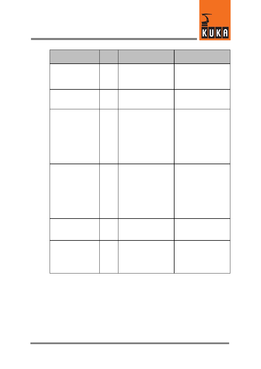
Interface signal
CI bus B board
Pin
Description
Remarks
24 V control voltage
+24 V internal
0 V internal
106
107
ESC power supply
max. 2 A
24 V control voltage
+VCC external
0 V external
88
89
In the absence of an ex-
ternal power supply, 24 V /
0 V must be jumpered in-
ternally (pins 88/106 and
89/107)
An external power supply
is recommended for inter-
linked systems.
24 V control voltage
+24 V
0 V
36
18
24 V control voltage
for supply to external
devices
max. 4 A
Optional. This control volt-
age is available to the cus-
tomer.
Caution: max. 4 A
24 V control voltage
+24 V
0 V
90
72
24 V control voltage
for supply to external
devices
max. 6 A
Optional. This control volt-
age is available to the cus-
tomer.
Caution: max. 6 A
Test output
Channel A
Channel B
15
16
Provides the pulsed volt-
age for the individual inter-
face inputs of both chan-
nels.
Connection example:
safety gate locking mech-
anism is connected under
channel B to pin 16
(TA_B) and pin 14 (B).
Safeguard
Channel A
Channel B
13
14
For dual--channel connec-
tion of a safety gate lock-
ing mechanism
max. 24 V, 10 mA
Only effective in AUTO-
MATIC mode
8
Interface signals (continued)
25 of 26
KRC2ed05 SafetyBus mit E/A 11.05.00 en
Interface signal
SafetyBUS Gateway
Pin
Description
Remarks
Test output
Channel A
Channel B
33
34
Provides the pulsed volt-
age for the individual inter-
face inputs of both chan-
nels.
Test outputs for the
start--up function
Start--up
Channel A
Channel B
31
32
Input, start--up
Input A
D0
D1
D2
D3
D4
D5
D6
D7
37
39
41
43
45
47
49
51
Digital safe inputs
Pulsed test output A
(TA24VA)
Input B
D0
D1
D2
D3
D4
D5
D6
D7
38
40
42
44
46
48
50
52
Digital safe inputs
Pulsed test output B
(TA24VB)
Test output
Channel A
Channel B
53
54
Provides the pulsed volt-
age for the individual inter-
face inputs of both chan-
nels.
Output
A0 (A)
A0 (B)
A3 (A)
A3 (B)
60
61
63
64
Digital safe outputs
switches 24 V of output
switches 0 V of output
switches 24 V of output
switches 0 V of output
24 V, resistive/inductive
load, max. 1 A
Interface, SafetyBUS with I/Os
26 of 26
KRC2ed05 SafetyBus mit E/A 11.05.00 en
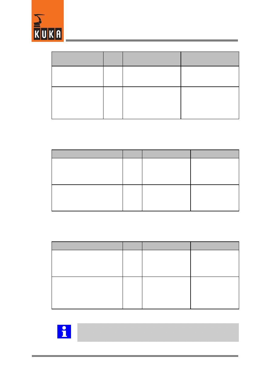
Interface signal
SafetyBUS Gateway
Pin
Description
Remarks
Return
RAE2--A0
RAE2--A1
62
65
24 V DC unpulsed
Relay contacts
Relay K11
Relay K12
Relay K13
Relay K14
73/74
75/76
77/78
79/80
Floating relay contacts
max. 8 A
8.2
Interface X111a IN
Interface signal
Pin
Description
Remarks
SafetyBUS
CAN L
CAN GND
CAN H
1
2
3
Bus signals
SafetyBUS input
24 V supply voltage
+24 V DC external
0 V external
1.
2.
ESC and SafetyBUS
Gateway power
supply.
Current max. 10 A
8.3
Interface X111b OUT
Interface signal
Pin
Description
Remarks
SafetyBUS
CAN L
CAN GND
CAN H
1
2
3
Bus signals
SafetyBUS output to
further control cabi-
nets.
24 V supply voltage
+24 V DC external
0 V external
1.
2.
Provision of the
24 V DC external
power supply for the
following control cabi-
net.
Further information
When establishing connections, observe the technical data in your specifica-
tions!
1

Index
Index -- i
C
CI3 bus board, 9
Commissioning, 23
Connectors, 10
E
ESC Safety System, 11
I
INB (A), 16
INB (B), 16
Installation positions of the connectors, 10
interlinked systems, 24
K
K11 -- K14, 9
S
Safety instructions, 7
SafetyBUS Gateway A, 9
T
Terminal block 2.2, 9
Troubleshooting, 23
U
Use, 5
X
X111, 10
X111a, 10
X111b, 10
Document Outline
- 1 Introduction
- 2 Safety
- 3 Product description
- 4 Power supply for ESC and SafetyBUS Gateway A
- 5 Start-- up function
- 6 Safeguard in system operation
- 7 Connector pin allocation
- 8 Interface signals
Wyszukiwarka
Podobne podstrony:
krc2 ed05 profibus en
krc2 ed05 pci en
krc2 ed05 interbus en
krc2 ed05 devicenet en
krc2 ed05 external axis 7,8 en
krc2 ed05 kcp holder en
krc2 ed05 20 A Han6 Power Infeed usa en
kb safety en
KRC2 ed05 Profibus
krc2 peri en
KR C2 ed05 Battery Monitoring en
BA KR C2 ed05 Main Switch with Cover en
Safety KR C4 en
new employee safety orientation 1201643571904060 5
Safety net
Budzik Versa wielkość karty kredytowej instrukcja EN
G2 4 PW EN wn Rys 01
więcej podobnych podstron