42
Home Power #63 • February / March 1998
Homebrew
G. Forrest Cook
©1998 G. Forrest Cook
T
his article is the companion for the
low voltage disconnect circuit in
HP #60. This circuit regulates the
charging of the battery in a solar system
by monitoring battery voltage and
switching the solar or other power
source off when the battery reaches a
preset voltage. A charge controller
circuit can increase battery life by
preventing over-charging which can
cause loss of electrolyte. The absence
of a relay and its associated coil current
makes this circuit efficient for small
systems as well as for systems using
larger current components.
This charge controller was designed for high efficiency,
use of common parts, and operation with common
ground circuitry. Some ideas used were inspired by an
article in
QST magazine, but this is a much simplified
circuit. A circuit board is available with both the charge
controller and low voltage disconnect circuits on one
board. The charge controller circuit has been used with
solar power input. It also functions well as a battery
charger when used with any current limited DC power
supply such as small “wall wart” transformers or a high
current supply with a series resistor.
Specifications
Night time current drain: 0.6 mA
Operational current drain: 19 mA (less without LEDs)
Maximum solar panel current: 3-10 Amps (see text)
Voltage drop during charging: 0.5 Volts at 1 Amp
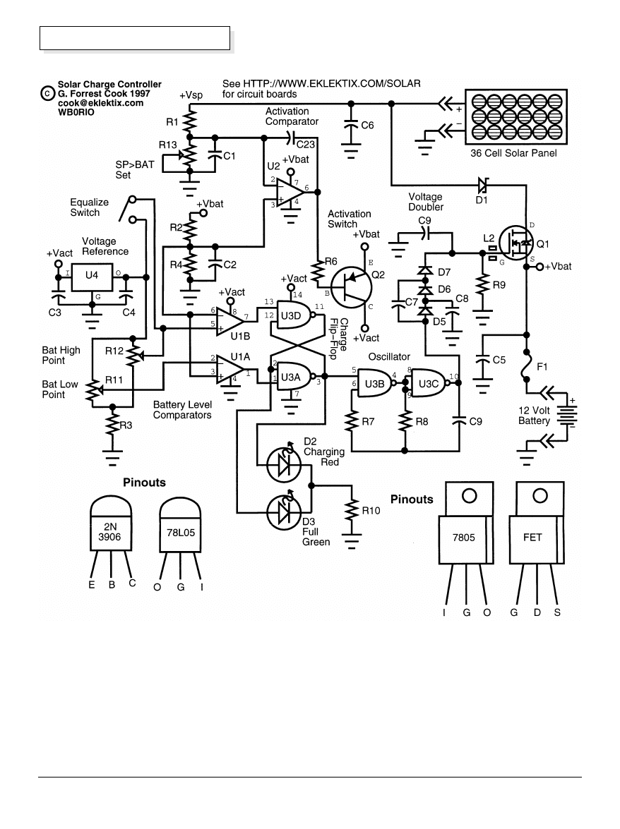
Theory
During charging, current flows from the solar panel
through diode D1, MOSFET transistor Q1, fuse F1, and
into the battery. Power MOSFET transistor Q1 is the
main switching device in the charge controller circuit. It
connects the solar panel to the battery when it is in
need of charging and power is available from the solar
panel. As with the LVD circuit, Q1 is set up in a “high
side” switch arrangement which allows for a common
ground circuit. This is helpful in automotive and other
applications. Switching efficiency is very high due to the
low “on” resistance of modern power MOSFETS,
usually under 0.1
Ω
. Diode D1 is a Schottky device
preventing back currents from flowing from the battery
to the solar panel. A regular silicon diode may be used
but a Schottky will have a lower forward voltage drop
and resulting higher efficiency. Fuse F1 provides a
safety limit on the current available from the battery in
the event of a short.
Comparator U2 is used to control power to the rest of
the charge controller circuit. When the solar panel
voltage is lower than the battery voltage, the rest of the
circuitry is disabled, reducing night time idle current to
the few milliamps consumed by U2 and its associated
input circuitry. When the solar panel voltage rises above
the battery voltage, the output of U2 goes negative,
switching on transistor Q2 which provides power to the
rest of the circuit. Resistor networks R1/R13 and R2/R4
scale the battery and solar panel voltages to a range
that is useful to U2. Capacitor C23 prevents oscillation
in the comparator at start up. Voltage regulator U4 is
used as a reference for the battery set points, the
reference points are adjusted via resistor network R11,
R12, and R3. Comparators U1A and U1B monitor the
battery voltage and switch states when the battery is
fully charged (U1B) or has dropped to a voltage where
charging should resume (U1A). The comparators drive
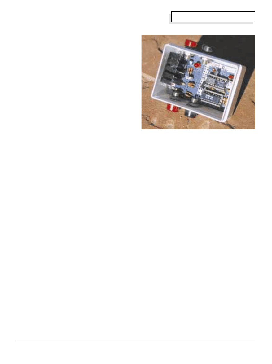
Above: Charge controller circuit board in action.
Homebrew
for Medium Power Applications
43
Home Power #63 • February / March 1998
Homebrew
a set-reset flip-flop circuit consisting of U3A and U3D.
The comparator outputs are inverted logic, on is low
and off is high. The output of the flip-flop is used to turn
the oscillator consisting of U3B and U3C on and off.
The flip-flop also drives the two LEDs used to indicate
charging or battery full states. The oscillator generates
a 10 kHz square wave that is stepped up to around 25
Volts DC by the voltage doubler circuit of D5, D6, D7,
and C7, C8, C21. The gate voltage is higher than the
battery’s 13 Volts, and is used to turn Q1 on fully.
Ferrite bead L2 is used to prevent oscillation in Q1.
Resistor R9 discharges the voltage doubler when the
oscillator is shut off. The technically picky may note that
all of the ICs comparators are really common op-amps,
not special purpose comparators. The op-amps are
wired in a comparator configuration. The circuit is fairly
dependent on the use of 741 and 1458 op-amp parts.
Other op-amps may require changing the values of R1
and R2. An equalize switch is included to allow for
occasional over-charging of the battery by raising the
threshold of the high voltage sensing comparator,
forcing the charge current on. Equalizing helps bring
lower voltage cells in the battery up to a full charge.
Alignment
Alignment equipment consists of a multi-meter, a
charged 12 Volt lead acid battery, and a 0-16 Volts DC
variable voltage power supply with a 10
Ω
25 watt
resistor in series with the positive lead to limit the
current. A word of caution is in order when dealing with
circuits involving potentially high battery currents: the
circuit should be placed on an insulating surface for
testing and all wiring should be insulated to lessen the
chance of creating a short circuit. Be sure not to
reverse the polarity of the battery wires, doing so may
damage the circuit. The voltages in this circuit present
no shock hazard but the currents present a potential
burn hazard.
The first step of the alignment is to set the charge
controller turn-on voltage with R13. Start by turning R12
fully clockwise (toward positive) and turn R11 and R13
fully counter-clockwise (towards ground). Connect the
charged 12 Volt battery to the battery terminals and
connect the current limited variable power supply to the
solar panel input on the charge controller. Connect the
volt meter across the Schottky Diode D1 with the
negative volt meter lead on the cathode (bar end) of the
diode. Adjust the variable supply from zero up to around
13 Volts until the meter reads about 0.3 Volts across the
diode. Slowly turn R13 clockwise until the red LED just
turns off, now turn R13 counter-clockwise again until
the red LED just turns on.
The second and third alignment steps involve setting
the low and high points that the battery will alternate
between when it is fully charged. Connect the volt
meter across the battery for this step. Turn the variable
voltage supply to 15 Volts. Adjust R12 counter-
clockwise until the green LED turns on. Adjust R11
clockwise until the red LED turns on. At this point, the
charge controller should be functioning and the LEDs
should alternate. Adjust R12 until the battery voltage
peaks at the desired high charge point. Richard Perez
recommends setting the high charge point to 13.8 Volts
for sealed gel-cells and to 14.5 Volts for flooded cell
(wet) lead-acid batteries. Richard also notes that these
values are for solar applications where the sun only
shines for part of the day, the values should be lower for
applications with continuous power sources. The
battery low set point should be set to 0.5 to 1 Volts
lower than the high set point, adjust R11 until the
battery drops to the desired voltage before the charging
cycle begins again. In a properly adjusted circuit, the
two LEDs should alternate several times per minute.
This varies with battery and solar panel capacities. If
the battery voltage drops too slowly during the test, it
may be helpful to connect a small 12 Volt lamp across
the battery, this will cause the battery to discharge
faster. It may also help to adjust the voltage of the
variable supply, this will vary the charging current and
duty cycle of the flip-flop.
Current Capacity
The current handling capacity of this circuit is
determined by the MOSFET transistor Q1, diode D1,
fuse F1, and the current carrying wires in the path
between the solar panel and the battery. An IRFZ34
MOSFET is rated at 30 Amps max and should easily
handle 10 Amp charging currents. A heat sink should be
used on the MOSFET and diode D1 if you are running
Above: Prototype charge controller on perf board.
44
Home Power #63 • February / March 1998
Homebrew
currents higher than 2 or 3 Amps through the circuit.
The peak current may be determined from the solar
panel specs. Diode D1 can be an IR 80SQ045 when
the max current is less than 8 Amps. higher current
diodes such as the GI MBR1045GI rated at 10 Amps
may also be used with a heat sink. For efficiency, it is
important to use a Schottky barrier diode since it has a
voltage drop of around 0.4 Volts under load while a
regular silicon diode has a voltage drop of around 0.8
Volts under load. At 5 Amps, the silicon diode would
waste 4 Watts while the Schottky diode wastes only 2
Watts. The circuit board version of this circuit can
handle about 8 Amps maximum if the proper
semiconductors are used. The fuse should be rated the
same as the maximum current of the FET or diode D1,
whichever is lower.
Construction
I built the prototype circuit on perforated circuit board
using point to point wiring. Teflon insulation over tinned
bare wire works well and does not melt under a
soldering iron. Be careful not to overheat any of the
45
Home Power #63 • February / March 1998
Homebrew
semiconductors, especially the LEDs. IC sockets may
save a lot of time and grief in circuit debugging. Wires
between the solar panel, D1, Q1, F1, and the battery
should be heavy gauge to handle the charging current.
Be sure to use thick wires for the current carrying part
of the circuit. In the prototype I built the circuit into a
small plastic box and used banana plugs as connectors
for the input and output terminals.
Use
Connect the solar panel to the solar panel terminals
and the battery to the battery terminals and watch the
battery charge up. When the LEDs alternately blink, the
battery is charged. A load may be connected between
ground and the fused C5-Q1 source junction if the load
current is lower than the fuse rating. The circuit board
has the companion LVD circuit connected in at this
point. Be sure to use battery cables that can handle the
load current. If the circuit is to be connected to a high
current source such as an automobile cigarette plug or
a high current capable power supply instead of a solar
panel, it will be necessary to use a high wattage series
resistor between the positive power source and the
charge controller solar panel input. A 10
Ω
, 25 watt
resistor would be a good value to start with.
Access
Author: G. Forrest Cook • WB0RIO •
2910 Carnegie Dr., Boulder, CO 80303 •
E-Mail: cook@eklektix.com • Web:
www.eklektix.com/gfc/elect/solar
Circuit Board: A blank 3 by 4.5 inch
circuit board with this charge controller
and the low voltage disconnect circuit
shown in HP #60 is available from
Eklektix, Inc. for $20. An 8 Amp circuit
board and parts kit is available for $45.
An 8 Amp assembled and tested circuit
board is available for $60. US Postage
is included, we are not set up to do
foreign orders yet. Assembly
instructions are included with bare
boards and kits. Make a postal money
order or check out to Eklektix, Inc.
Parts
Digi-Key • 1-800-DIGIKEY
Newark Electronics • 1-800-4NEWARK
Mouser Electronics • 1-800-346-6873
Article
The FET Charge Controller, by Michael
Bryce • WB8VGE,
QST, January 1992
Parts List
U1
1458 dual op-amp
U2
741 op-amp
U3
4011 CMOS quad nand gate IC
U4
78L05 or 7805 voltage regulator IC
Q1
IRFZ34 power MOSFET, see text
Q2
2N3906 PNP silicon transistor
D1
80SQ045, or MBR1045GI Schottky diode, see text
D2
Red LED
D3
Green LED
D5-D7
1N4148 silicon switching diode
C1-C8,C21,C23 0.1
µ
F ceramic disc capacitor
C9
0.001
µ
F ceramic disc capacitor
C20
100
µ
F 16V electrolytic capacitor
R1-R3,R7
100K
Ω
1/4w resistor
R4
39K
Ω
1/4w resistor
R6,R10
2.2K
Ω
1/4w resistor
R8
47K
Ω
1/4w resistor
R9
1M
Ω
1/4w resistor
R11-R13
100K
Ω
10 or 15 turn trimmer potentiometer
F1
DC fast blow fuse, see text
L2
ferrite bead or 3 turns #24 wire on a 22
Ω
1/4w resistor
Heat Sink
TO-220 finned heat sink on Q1
for greater than 3A capacity (don't ground the Q1 tab, it's hot)
Battery
12 Volt lead acid flooded or gel cell battery
Solar Panel
36 cell photovoltaic panel, see text about maximum current
Tired of high utility bills?
Let the SUN “COOL” your home!
SOLAR
EVAPORATIVE COOLER
• No batteries needed
• Distributes 1,000 to 4,500 CFM
• Great for city use - don’t pay local utility
• Operates on direct current from solar panel(s)
• For use in desert or arid climates
FREE CATALOG
A Premier Manufacturer of Quality Solar Products
SUNAMP POWER COMPANY
7825 E. Evans Rd., Ste. 400
Scottsdale, Arizona 85260
1-800-677-6527
Wyszukiwarka
Podobne podstrony:
Home Power Magazine Issue 072 Extract p34 Solar Hot Air Collectors
Home Power Magazine Issue 095 Extract p22 Solar Electric Grid Tie
Home Power Magazine Issue 037 Extract p22 Solar Cooker Contest
Home Power Magazine Issue 109 Extract pg22 Making Sense of Solar Electricity Costs
Home Power Magazine Issue 057 Extract p62 Food Dehydrator
Home Power Magazine Issue 032 Extract p22 Whats An Inverter
Home Power Magazine Issue 021 Extract p78 Electric Fence Charger And Time Machine
Home Power Magazine Issue 032 Extract p78 Me And My Panel
Home Power Magazine Issue 109 Extract p12 Off Grid Living In The City
Home Power Magazine Issue 055 Extract p72 Surge Arresters For Lightning And EMP Protection
Home Power Magazine Issue 039 Extract p74 Exceltechs 1000 Watt Sine Wave Inverter
Experimental Study On Stirling Engine Generator And Solar Receiver System For Future Space Applicati
Home Power Magazine 024 Extract p26 p30 All Solar Panels Ever Tested
Home Power Magazine Extract Installation Basics For Solar Domestic Water Heating Systems Part 2
Home Power Magazine Extract Installation Basics For Solar Domestic Water Heating Systems Part 1
[ebook renewable energy] Home Power Magazine 'Correct Solar Panel Tilt Angle to Sun'
[ebook renewable energy] Home Power Magazine 'Correct Solar Panel Tilt Angle to Sun'
Home Power Magazine 012 Aug Sep 1989 Renewable Solar Wind Energy
Home Power Magazine 007 Oct Nov 1988 Renewable Solar Wind Energy
więcej podobnych podstron