
Closed loop antifreeze
is one of the most
common solar domes-
tic hot water (SDHW)
systems for cold
climates. This article
concentrates on the as-
sembly and installation
of closed loop anti-
freeze SDHW systems,
hereinafter referred to
as closed loop sys-
tems. “Installation
Basics for SDHW
Systems” in HP94
covered aspects of
installation common to
most solar water
heating installations,
such as collector
location and mounting,
pipe runs, soldering
and insulation, and the
control system.
42
home power 95
SDHW Installation Basics
Part 2: Closed Loop Antifreeze
Chuck Marken & Ken Olson
©2003 Chuck Marken & Ken Olson
Nancy Cochrell of AAA Solar puts the
finishing touches on a SDHW system.
43
www.homepower.com
hot water
how to
The operation of the closed loop
system, the function of each of its
components, and some guidelines for
sizing were covered extensively in
HP85. In brief, freeze protection is
accomplished by circulating a nontoxic
antifreeze fluid to remove heat from
the solar collectors and transfer it to
the domestic water via a heat
exchanger. The antifreeze remains
contained within a closed loop, so it
never mixes with the domestic water.
The collector loop setup is nearly
identical to conventional closed loop
hydronic home heating systems,
which circulate water heated in a
boiler through baseboard radiators or
a radiant floor. Most plumbing and
heating contractors recognize the
closed loop system as a common
design and are familiar with all the
components on the parts list in this
article.
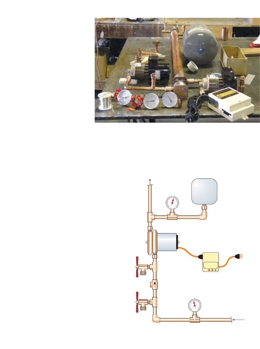
Modular Assembly Rules!
The major components, other than solar collectors and
storage tanks, are easier to deal with if you have the space to
assemble the parts into a component module before
installation. Many modules in earlier systems had cosmetic
covers, but this has been shown to cause excessive heat
buildup, which can cause premature failure of certain
pumps. The components can be placed anywhere consistent
with good access and straightforward pipe runs, but they
are usually installed near the storage tank.
A
3
/
4
inch (19 mm) plywood board, approximately 2 or 3
feet (0.6 or 0.9 m) by 4 feet (1.2 m), is an excellent mounting
surface for the component module. You can also use a
square channel product called UniStrut for wall-hung
equipment. If you have the space on a wall for a module of
this size, the installation will be much cleaner, with less
chance of piping errors. Placement of the components is
based on convenience and access, and a few good rules as
provided below and illustrated in the drawings.
When your module is completed, you will have either
two or four connections to the rest of the system. For
systems using an external heat exchanger, you will have
four connections, including collector supply, collector
return, heat exchanger supply, and heat exchanger return.
For systems with a heat exchanger integrated within the
storage tank, you will have only two module connections—
one that goes to the collector and one to the tank heat
exchanger.
Rule #1
The pumps should be placed so that they are pumping
the coldest fluid in the system. The coldest collector loop
fluid is found after it has been circulated through the heat
exchanger where it has lost most of its heat. The coldest
DHW is at the bottom of the storage tank.
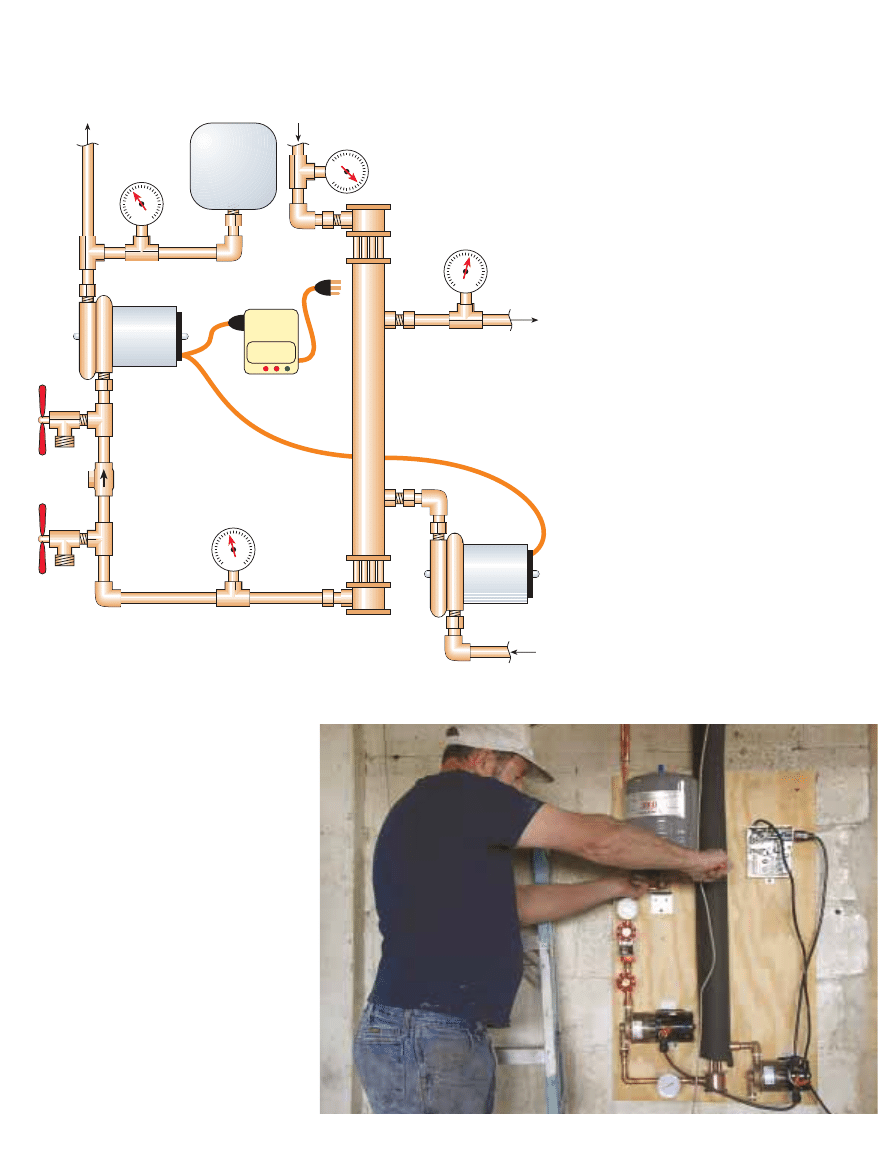
Pressure Gauge:
0 to 100 psi
Valve:
Fill
Valve:
Drain
Temperature Gauge:
30
°
to 250
°
F scale
Expansion
Tank
Pump:
Glycol solution
Check
Valve
Differential
Controller
From
Heat Exchanger
in Tank
To Solar Collector
To Power
Supply
SDHW Module
for Use with In-Tank
Heat Exchanger
Laying out the components and plumbing parts in advance
prevents headaches after the soldering begins.
home power 95 / june & july 2003
hot water
how to
44
Rule #2
Pumps should always be mounted
so that the impeller shaft is horizontal.
Mounting a pump with the shaft
vertical will put too much pressure on
the shaft bearings and cause
premature failure. If possible, the
pump(s) should pump upwards; this
prevents trapped air from collecting in
the pump chamber, which is possible
with some pump models.
Rule #3
The check valve should be placed
between the two boiler drain valves
that are used for purging and filling
the system. These boiler drains are also
used for any future maintenance of the
collector loop fluid.
Rule #4
The expansion tank, pressure
gauge, and the boiler drain and check
Pressure Gauge:
0 to 100 psi scale
Valve:
Fill
Valve:
Drain
Temperature Gauge:
30
°
to 250
°
F scale
Expansion
Tank
Check
Valve
Differential
Controller
From Tank
To Solar
Collector
To Power
Supply
Pump:
Potable water
From Solar
Collector
Heat
Exchanger
Pump:
Glycol solution
To Tank
Temperature Gauge:
30
°
to 250
°
F scale
Temperature Gauge:
30
°
to 250
°
F scale
valve assembly are usually placed
downstream from the heat exchanger,
near the collector fluid pump.
Therefore, they are on the cold side of
the loop as well.
Rule #5
If you place the expansion tank
with the pipe fitting down (tank
upside down), the tank will continue
to function if the internal bladder fails.
An expansion tank placed with the
fitting horizontal will still hold air with
a bladder failure, and may continue to
function. A tank placed with the fitting
up, upon failure, will introduce all the
air in the tank to the collector loop
piping. This is a common cause of
failure in older systems.
Rule #6
A coin vent may be located
anywhere that an air pocket is likely to
form within the piping. Air pockets are
most likely to form where the fluid is
at its hottest, or where the piping
makes a downward turn. A coin vent is
usually placed at the collector outlet
where the piping turns downward.
Another may be located at a similar
location in the collector loop at the
closed loop module assembly.
Don Keefe mounts the expansion tank upside down—on purpose.
SDHW Module with
External Heat Exchanger
45
www.homepower.com
hot water
how to
Putting It All Together
The parts should be laid out dry before putting them
together. You will need to cut pipe to the sizes needed, and
fit the pipe into the various fittings and adapters. All of the
piping, fittings, adapters, and components should be
soldered before attaching them to the module backing.
Gaskets should be removed from valves and other
components, and set aside before soldering. Reassemble
them once the fittings have cooled down.
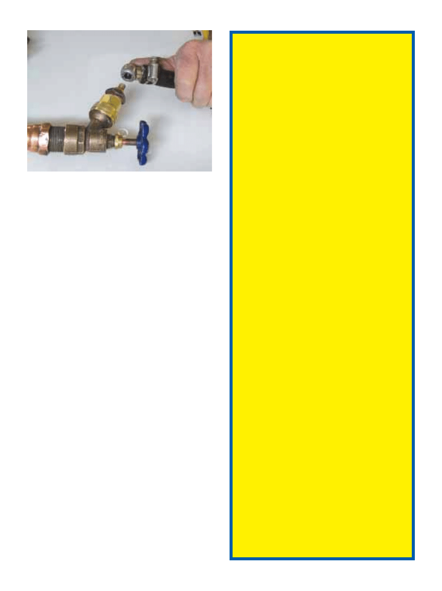
The assembly can be pressure tested with a small air
compressor if you are unsure of any joints in the system. You
can make a small attachment for the pressure test with a
hose connector and Schrader valve (tire valve) as shown.
This can be screwed onto one of the boiler drain valves in
the open position. Cap the inlets and outlets, and the
pressure gauge will indicate the assembly pressure.
If the system holds a pressure of about 50 psi for 30 to 60
minutes, you can be assured of its integrity. If the pressure
gauge falls during this time and the leak is not apparent, a
solution of soap and water can be applied with a spray
bottle to detect very small leaks. Soap bubbles will appear at
the leaking joint(s).
When you feel that the module is leak-free, the entire
assembly should be fastened to the module backing and the
backing fastened to the wall with screws or lag bolts. Four
screws or lag bolts, one at each corner, should be enough
since the whole apparatus only weighs 30 to 40 pounds
(17–18 kg).
The piping to and from the collectors and storage tank
can be soldered with the module in place. Some installers
prefer to use unions at connections to major system
components, such as the closed loop module or the heat
exchanger. Unions are merely a convenience for
maintenance and repair if removal or replacement is
anticipated.
At a minimum, a SDHW closed loop installation
with collectors placed on a roof, will require the
parts listed below.
Solar Collector(s)
Solar collectors capture the heat from the sun
and are the main components of the system. In
addition to your collectors, you will need mounts
and hardware, roof jacks, silicone caulking, and
roof sealant. (See “Installation Basics” HP94.)
Pump(s)
A closed loop system uses a low head,
centrifugal circulating pump with a cast iron,
stainless steel, or bronze body and is able to
pump at least 0.5 to 1 gpm (2–4 lpm) for each 4
by 8 foot (1.2 x 2.4 m) collector. If your system
has an external heat exchanger, you will need an
additional circulating pump on the water side of
the heat exchanger. This pump should have a
bronze, stainless steel, or high-temperature
plastic body. Be sure you have pump-to-pipe
flanges if you use flanged pumps. (See
“Installation Basics” HP94
.)
Differential Control
A differential control activates the system
whenever useful solar heat can be collected. It
senses the difference in temperature between
the solar collectors and the storage tank and
turns the pump on or off accordingly.
You will also need two sensors and a 120 VAC
receptacle and cord set, unless the control
includes a cord set. Thermostat wire for the
control sensor wiring should be #20 or #22 (0.5 or
0.3 mm
2
), two-conductor jacketed cable. Use
stainless steel hose clamps for fastening the
sensors to the pipes. Connect the sensor wires to
the sensors with electronic solder, coat with
silicone sealant, and cover the connections with
small wire nuts. (See “Installation Basics” HP94.)
Heat Exchanger
The heat exchanger, which transfers the heat
from the solar heated antifreeze to the domestic
water in the storage tank, can be either external
or inside the tank. (See "Heat Exchangers" HP92.)
Storage Tank
Solar hot water is typically stored in a tank that is
separate from the backup water heating system.
Your storage tank may come with or without an
integral heat exchanger.
SDHW Closed Loop
Parts List
A pressure test fitting made from a Schrader valve
and a female hose fitting.
Continued on page 46
46
home power 95 / june & july 2003
hot water
how to
Connecting to the Heat Exchanger
Connecting the preassembled module to a tank with an
integrated heat exchanger is rather straightforward. The
heat exchanger outlet (cold) feeds the pump inlet, and the
collector outlet connects to the heat exchanger inlet (hot).
The tank’s standard water inlet and outlet connections
should be fitted with dielectric unions where copper pipe
connects to the steel tank. This prevents galvanic corrosion
between dissimilar metals.
A temperature/pressure relief (TPR) valve must be
installed on the storage tank if there are any valves between
the storage tank and the conventional water heater. The
outlet of the TPR valve should either discharge at a floor
drain, connect with a tee to the TPR discharge of the
conventional water heater, or be piped outside. If you pipe
it outside, make sure the open end faces downward and is
at least 6 inches (15 cm) and not more than 24 inches (61 cm)
above ground level.
One and Two-Tank Storage Systems
Most SDHW systems use a separate tank to store solar
heated water. This is in addition to the backup auxiliary
water heater. Cold water supply from the house will feed
the cold inlet of the solar tank. The hot outlet of the solar
tank will feed the cold inlet of the auxiliary gas or electric
water heater. You can install a bypass valve assembly as
shown in the diagram to bypass the auxiliary tank during
months when the sun heats 100 percent of your hot water.
You may consider installing a single tempering valve
downstream from the tanks to avoid sending exceedingly
hot solar heated water to the tap during those bountiful
sunny and warm months. But tempering valves can be a
problem in areas with hard water. The spring in the valve
that mixes the water can become clogged in a few years, and
the valve interior may need to be cleaned or replaced.
For smaller systems with an external heat exchanger and
electric backup, you can save space by modifying a single,
oversized, standard electric water heater to function as both
backup and solar hot water storage. See the “One-Tank”
how-to article in next issue for directions on making these
modifications.
Expansion Tank
A #15 bladder-type expansion tank is sufficient
for fluid volumes up to 4.7 gallons (18 l). For
greater volumes, you may use multiple tanks, or
a #30 is sufficient up to 12.5 gallons (47 l).
Pressure Relief Valve
A pressure relief valve rated at 50 to 75 psi is
usually adequate to protect the closed loop piping.
Pressure Gauge
A pressure gauge that registers in the range of 0
to 100 psi will work.
Coin Vent or Automatic Air Vent
Coin vents are preferred. Automatic air vents
may be problematic outdoors in freezing
climates. Manual coin vents are adequate for
closed loop systems where no makeup fluid is
automatically introduced into the system.
(Makeup water is a common feature in large
hydronic heating systems where water is
automatically introduced into the system to
make up for losses or leaks over time. This is not
common in solar water heating systems.)
Boiler Drain Valves
You will need two boiler drain valves for purging
and filling the system.
Check Valve
Spring-type check valves are recommended to
prevent forward or reverse flow at night.
However, swing-type check valves are recom-
mended for use with PV powered DC pumps,
which may not generate enough force to open a
spring-loaded check valve.
Miscellaneous Plumbing Parts
You will need some
3
/
4
or 1 inch Type M copper
tubing and various copper elbows, tees,
adapters, and unions as required. You will also
need solid wire solder (type 95/5; don’t use rosin
core solder intended for electronics) and flux,
high temperature pipe insulation, insulation
covering, and propylene glycol—approximately
1 gallon (4 l) per collector.
Options to Think About
Consider adding dial thermometers or choosing
the option of digital temperature readouts on the
control if available. Another nice option is the
addition of three ball valves for the hot water
bypass assembly. Ball valves are preferable to
gate valves because the position of the handles
indicates whether the valves are open or closed.
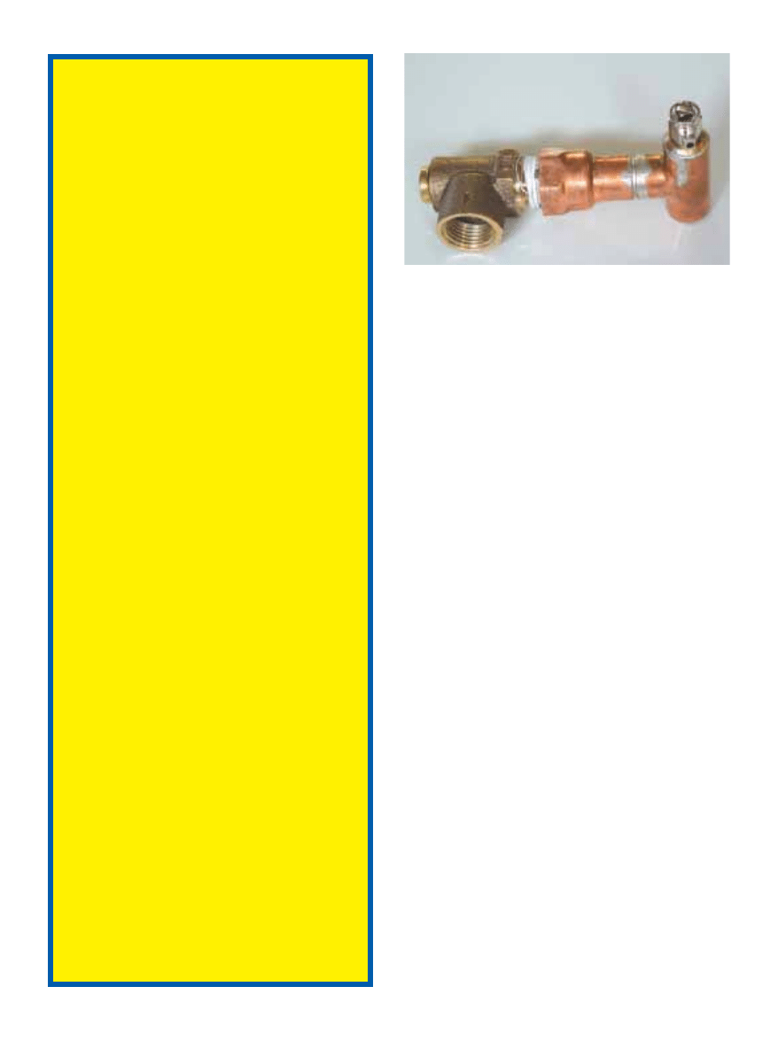
Parts List, Continued
A pressure relief valve and air vent is installed at the highest
piping point in the system—the outlet of the solar collector(s).
47
www.homepower.com
hot water
how to
For situations with limited space, you also might
consider using a tankless or on-demand heater for auxiliary
backup. In this case, the hot outlet of the solar storage tank
feeds the inlet of the on-demand heater. For this
configuration to work, you must be sure that the on-demand
heater is able to sense the incoming water temperature and
regulate the outlet temperature. This way it will only
operate to the extent that the solar preheated water needs to
be boosted in temperature. The AquaStar “S” model
functions in this way and is therefore compatible with solar
water heating systems. (See “Solar Hot Water, Homebrew
Style,” HP88).
Tankless water heaters may need cleaning after a few
years in locations with hard water. If you need to clean
automatic coffee makers with vinegar frequently, this same
type of periodic maintenance may be required with a
tankless water heater.
Collector Loop Fluids
When the collectors are securely mounted and all
components are assembled and wired as shown in these
drawings and according to the manufacturers’ instructions,
you are ready to test the whole system for leaks, purge it,
and fill it with an antifreeze solution or synthetic oil.
The most common fluid used in closed loop systems is a
50-50 solution of propylene glycol and water. This will give
freeze protection down to approximately –30°F (–34°C).
Propylene glycol is similar to car antifreeze (ethylene
glycol), but is nontoxic. Ethylene glycol is not
recommended, but may be used in systems with double-
walled heat exchangers. You should be aware of its toxicity
and the potential danger from possible future leaks.
Most propylene glycol is distributed with inhibitors or
buffers that prevent it from turning acidic over long periods
of time. These inhibitors (aluminum hydroxide is a common
one) can break down at high temperatures (above 280°F;
138°C). When the buffers are gone, the glycol solution can
turn acidic. A higher temperature (325°F; 163°C) propylene
glycol is available, but the boiling points of both of these
glycols are the same—approximately 225 to 250°F
(107–121°C), depending on system pressure.
Synthetic oils have an advantage over glycol solutions
because they will not boil under any temperatures produced
by flat plate solar collectors. They make a system
maintenance-free in this respect. The disadvantages of
silicone oil are reduced efficiency due to its lower specific
heat, limited availability, and high cost. A gallon of 50-50
glycol solution costs an average of US$7 to US$10. Silicone
oil can cost US$75 a gallon or more.
Two other synthetic oils have been used in closed loop
systems, bray oil and dyala oil, but the use of these requires
a heavy caution. Neither of these oils is compatible with the
butyl rubber used in O-rings, gaskets, and the bladder in
expansion tanks. These oils need special O-rings and
gaskets made from Viton, a material manufactured by
Dupont. Expansion tanks are no longer made with bladders
of this material, and that poses a significant installation
problem when considering these synthetic oils as an option.
Purging & Checking for Leaks
Other options are available for purging and filling the
system, but the method employed most often uses a charge
pump capable of creating more than 15 psi pressure in the
closed loop. It must also be capable of lifting the charge fluid
as high as the collectors. A charge pump can be as simple as
a drill-operated pump found in many catalogs and home
centers. This type of pump has hose fittings on either end,
and connects easily to the system’s boiler drain valves.
Three washing machine hoses, two common garden hoses,
and a five-gallon bucket or other suitable container
completes a minimum setup for purging and filling the
system.
A closed loop SDHW system will have many solder
joints, and it is a good idea to clean the system out before
charging it with an antifreeze solution. To do this, you will
need a garden hose or two to drain the system if the
component module is located where you don’t want water
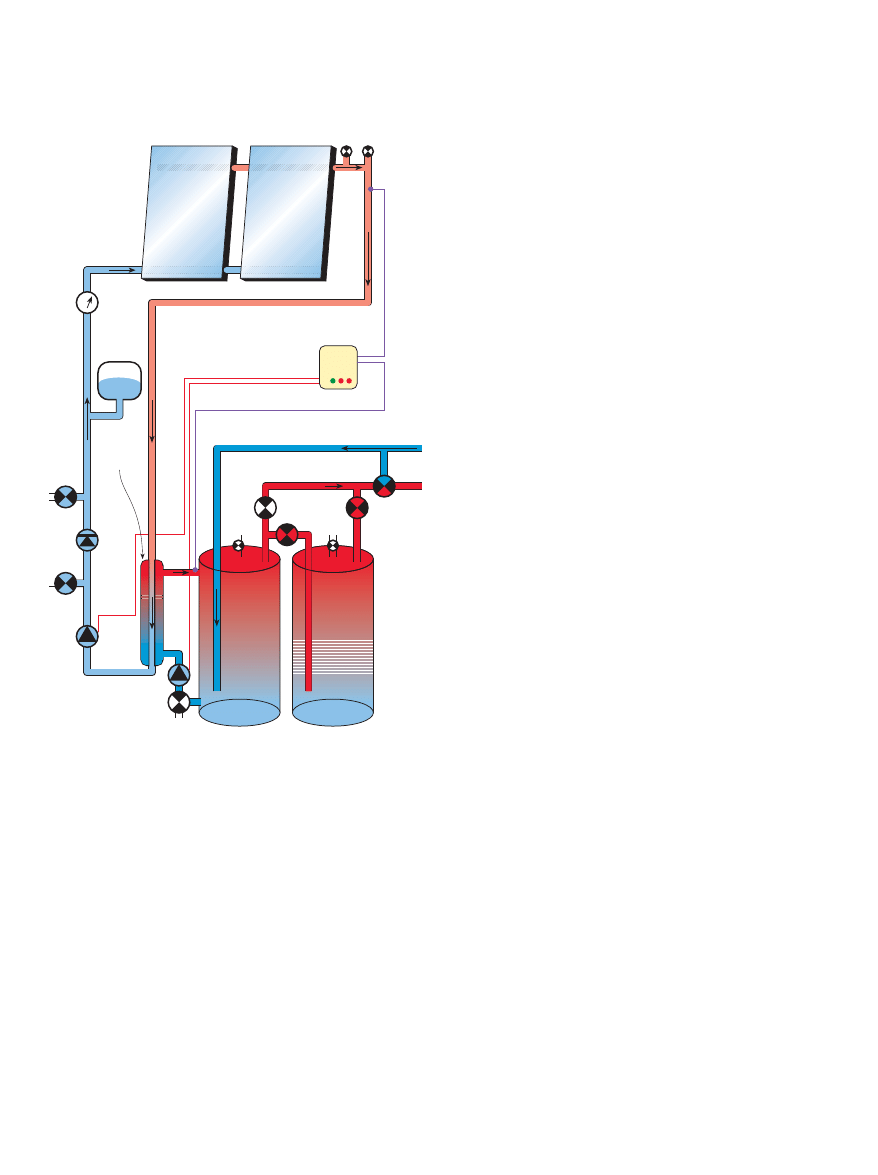
Flat Plate
Solar
Collectors
Heat
Exchanger
Expansion
Tank
Check
Valve
Drain
Conventional
Water Heater
Air Vent
Glycol
Pump
Pressure
Gauge
DHW Pump
Pressure
Relief
Valve
Glycol
Drain
Mixing
Valve
Cold in
from House
Hot out
to
House
Glycol Solution in Loop
T & P
Valve
Solar Storage
Tank
Sensor
Glycol
Fill
T & P
Valve
Sensor
Differential
Controller
Complete SDHW System
with Tank Storage
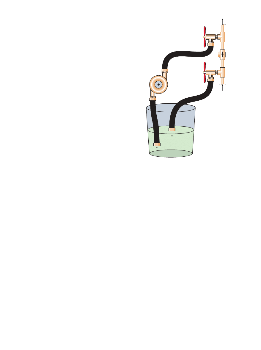
Valve: Fill
Valve: Drain
Check Valve
To Solar
Collector
From Heat
Exchanger
Charge Pump
Washer
Hoses
Bucket
Antifreeze Solution
on the floor. Washing machine hoses have female thread
hose connections on both ends. Using two of these hoses,
connect one end of each hose to the two boiler drain valves.
Connect the other end of each washing machine hose to
each of the boiler drain valves. The other end of each
washing machine hose is connected to one of the garden
hoses. One garden hose is connected to a hose bibb to
supply water, and the other is used to direct the discharge
water outdoors or to a drain after it has been circulated
through the system.
The supply water from the hose bibb is circulated
through the boiler drain fill valve located downstream from
the check valve. The arrow of the check valve should point
to the fill valve. The water can only go one way, and will
eventually return through the other boiler drain (discharge)
valve located upstream from the check valve. If the sun is
shining when you purge the system, the collector will heat
the water a bit and help clean out the flux, in addition to
purging any other debris that might be in the system.
When the water appears at the discharge hose, let it run
at full flow for a few minutes to get the air out of the system.
You may then shut off the upstream (discharge) boiler drain
and slowly close the downstream (fill) boiler drain where
the water is being introduced. Watch the pressure gauge and
let the house pressure bring the system up to about 25 to 40
psi. Then shut the valve completely.
Turn the differential control to the “on” position and
make sure it is plugged in. If the system is wired correctly,
the pumps should start up, even without sunshine. If the
sun is shining, you will be able to feel a difference in
temperature between the pipes to and from the collectors.
This assumes that most of the air was forced out of the
system by the garden hose water. You can then let the
system run for a few minutes or longer if you wish—the
hotter it becomes, the better it will clean out any flux left in
the system. While the system is circulating the water, you
can disconnect the downstream supply (fill) garden hose
from the hose bibb, after tuning it off.
This is also a good time to visually inspect all joints in
the system for leaks. When the water has circulated for at
least thirty minutes, turn the control to “off” and
immediately open both boiler drain valves to allow the
water to drain from the system. To drain all the water out,
you may need to open the air vent at the collectors to
introduce air at the top of the system.
Charging the System with Antifreeze
Fill the bucket with a 50-50 solution of water and
propylene glycol. You will almost always need about 2
gallons (7.6 l) of solution per collector (1 gallon of glycol) but
the quantity will vary with the collector manufacturer, size
of the collector, and size of piping in the system. Make sure
to have a little extra if in doubt.
You will now only use the washing machine hoses. One
hose is connected to the supply boiler drain valve,
downstream of the check valve, with its other end connected
to the charge pump output. Another hose goes from the
pump to the bottom of the bucket, and the third hose goes
from the discharge boiler drain valve, upstream from the
48
home power 95 / june & july 2003
hot water
how to
Charging
the System
with Glycol
check valve, to anywhere in the bucket. You may need to
elevate the bucket so that both hoses can reach it. The hose
attached to the pump will need to reach the bottom of the
bucket.
Open both valves all the way. Start the pump. Solution in
the bucket will be sucked up into the closed loop. You will
know that the system is full when the solution returns to the
bucket from the other hose. The return hose will contain a
good deal of air that is being forced out of the system. Let
the fluid circulate until the return hose is flowing smoothly
with no air bubbles. Close the upstream (discharge) valve at
this time. The flow in the return hose will stop and the
pressure will increase.
Keep the pump on until the system pressure is about 15
to 25 psi and then shut the fill valve downstream of the
check valve. Shut the pump off. Turn the control switch to
the “auto” position, and if the sun is shining, the pump(s)
should turn on. Leave the hoses connected. The system will
normally still have a small amount of air at the top. This air
can be released if you have installed a coin vent or automatic
air vent at the top of the system. Unscrew the coin vent or
push on the stem in the Schraeder valve of the automatic
vent until only liquid appears. Be careful—it might be very
hot, depending on the amount of sunlight.
Follow-up & Maintenance
Installation follow-up starts with casual observation
during the first couple of weeks after starting the system up.
The system should turn on shortly after the sun comes up,
but exact times are hard to gauge. The turn-on time changes

49
www.homepower.com
hot water
how to
with the seasons and the temperature of the cold water. The
system should also turn off before sundown. Micro-bubbles
of air are usually present in the water used in the antifreeze
solution, and these will tend to gather at the very top of the
piping. A couple of weeks after the system is started up, the
coin vent should be opened slightly to release any
accumulated air. If you used an automatic air vent, this
should have purged the air automatically.
A good, quick check of your system operation may be
made at the pipes coming to and from the collectors. When
the sun is shining and the water in the storage tank is cold
or cool, there should be a very noticeable difference in the
temperature of the two pipes. If not, there is something
wrong with the system. We’ll discuss what might be wrong
in a future article in this series.
We have covered the practical installation considerations
of a closed loop type of solar domestic hot water system.
This is one of the most common types of systems with
reliable freeze protection. In subsequent issues of Home
Power, we will follow up with installation of the drainback-
type SDHW system and the troubleshooting, maintenance,
and repair of both these types of systems.
Access
Chuck Marken, AAA Solar Supply Inc., 2021 Zearing NW,
Albuquerque, NM 87104 • 800-245-0311 or 505-243-4900 •
info@aaasolar.com • www.aaasolar.com
Ken Olson, SõL Energy, PO Box 217, Carbondale, CO 81623 •
720-489-3798 • sol@solenergy.org • www.solenergy.org
Controlled Energy Corp., 340 Mad River Park, Waitsfield,
VT 05673 • 800-642-3199 or 802-496-4357 •
sales@controlledenergy.com • www.controlledenergy.com •
AquaStar on-demand tankless water heaters
Wyszukiwarka
Podobne podstrony:
Home Power Magazine Extract Installation Basics For Solar Domestic Water Heating Systems Part 1
Home Power Magazine Extract Low Voltage Battery Disconnect
Home Power Magazine Extract ThermoElectric Generators
Home Power Magazine 003 Feb 1988 Renewable Solar Wind Energy
Home Power Magazine 001 Nov 1987 Renewable Solar Wind Energy
Home Power Magazine Extract Inverter Safety
Home Power Magazine Issue 063 Extract p42 Solar charge controller for Medium Power Applications
Home Power Magazine Issue 072 Extract p34 Solar Hot Air Collectors
Home Power Magazine 024 Extract p26 p30 All Solar Panels Ever Tested
Home Power Magazine Issue 109 Extract pg22 Making Sense of Solar Electricity Costs
Home Power Magazine Issue 095 Extract p22 Solar Electric Grid Tie
Home Power Magazine Issue 055 Extract p72 Surge Arresters For Lightning And EMP Protection
Home Power Magazine Issue 037 Extract p22 Solar Cooker Contest
[ebook renewable energy] Home Power Magazine 'Correct Solar Panel Tilt Angle to Sun'
[ebook renewable energy] Home Power Magazine 'Correct Solar Panel Tilt Angle to Sun'
Home Power Magazine 012 Aug Sep 1989 Renewable Solar Wind Energy
Home Power Magazine Issue 057 Extract p62 Food Dehydrator
Home Power Magazine Issue 032 Extract p22 Whats An Inverter
Home Power Magazine 007 Oct Nov 1988 Renewable Solar Wind Energy
więcej podobnych podstron