EMISSION CONTROL SYSTEMS
CONTENTS
page
page
COMPONENT REMOVAL/INSTALLATION
. . . . . 13
EVAPORATIVE EMISSION CONTROLS
. . . . . . . . 4
EXHAUST EMISSION CONTROLS . . . . . . . . . . . . 9
GENERAL INFORMATION
. . . . . . . . . . . . . . . . . . 1
GENERAL INFORMATION
VEHICLE EMISSION CONTROL INFORMATION
(VECI) LABEL
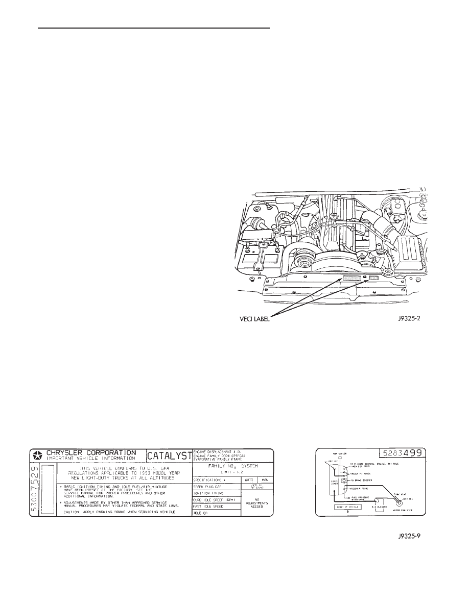
All vehicles are equipped with a combined VECI
label. The label is located in the engine compartment
(Fig. 1). The label contains the following:
• Engine family and displacement
• Evaporative family
• Emission control system schematic
• Certification application
• Engine timing specifications (if adjustable)
• Idle speeds (if adjustable)
• Spark plug and plug gap
The label also contains an engine vacuum sche-
matic. There are unique labels for vehicles built for
sale in the state of California and the country of
Canada. Canadian labels are written in both the En-
glish and French languages. These labels are perma-
nently attached and cannot be removed without de-
facing information and destroying it.
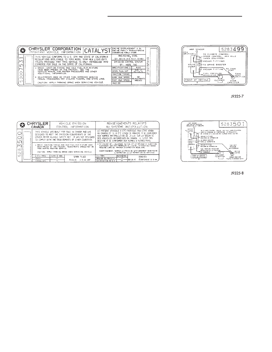
The following label illustrations are used as
examples only. If there are any differences between
these illustrations and the VECI label, those shown
on the VECI label should be used.
Fig. 1 VECI Label Location
FEDERAL VECI LABEL—TYPICAL
Z
EMISSION CONTROL SYSTEMS
25 - 1
VACUUM HOSE ROUTING SCHEMATICS
The following vacuum hose routing schemat-
ics are used as examples only. If there are any
differences between these schematics and the Vehicle
Emission Control Information (VECI) label schemat-
ics, those shown on the VECI label should be used.
CALIFORNIA VECI LABEL—TYPICAL
CANADIAN VECI LABEL—TYPICAL
25 - 2
EMISSION CONTROL SYSTEMS
Z
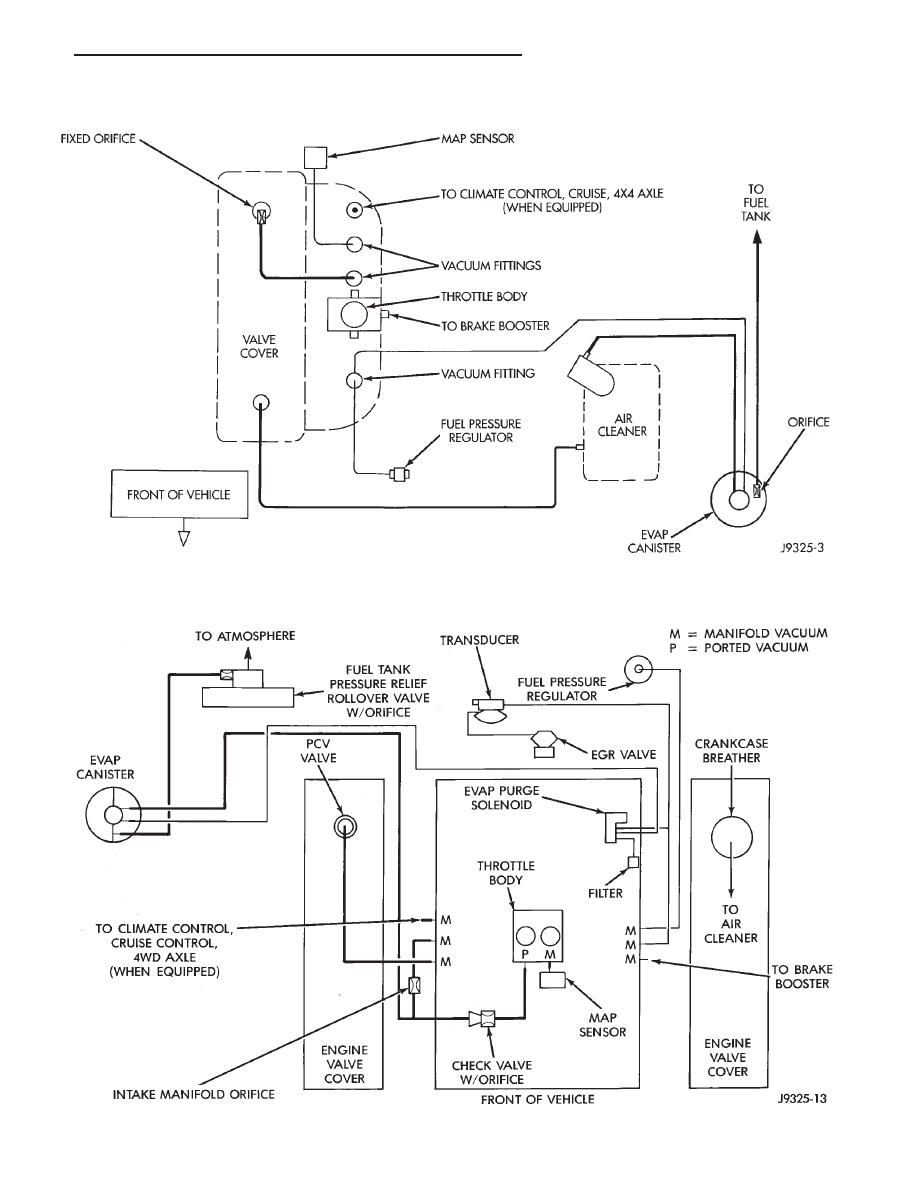
VACUUM ROUTING SCHEMATIC—4.0L ENGINE
VACUUM ROUTING SCHEMATIC—5.2L ENGINE—TYPICAL
Z
EMISSION CONTROL SYSTEMS
25 - 3
EVAPORATIVE EMISSION CONTROLS
INDEX
page
page
Crankcase Breather/Filter—5.2L Engines
. . . . . . . . 8
Crankcase Ventilation System—4.0L Engine
. . . . . . 5
EVAP (Evaporation) Control System
. . . . . . . . . . . . 4
EVAP Canister
. . . . . . . . . . . . . . . . . . . . . . . . . . . . 4
Evap Canister Purge Solenoid—5.2L Engine . . . . . . 5
Fuel Tank Filler Tube Cap
. . . . . . . . . . . . . . . . . . . 5
Positive Crankcase Ventilation System
. . . . . . . . . . 5
Pressure Relief/Rollover Valve
. . . . . . . . . . . . . . . . 8
EVAP (EVAPORATION) CONTROL SYSTEM
GENERAL INFORMATION
The function of the EVAP control system is to pre-
vent the emissions of gasoline vapors from the fuel
tank into the atmosphere. When fuel evaporates in
the fuel tank, the vapors pass through vent hoses or
tubes to a carbon filled EVAP canister. They are tem-
porarily held in the canister until they can be drawn
into the intake manifold when the engine is running.
The EVAP canister is a feature on all models for the
storage of fuel vapors from the fuel tank.
The hoses used in this system are specially
manufactured. If replacement becomes necessary,
it is important to use only fuel resistant hose.
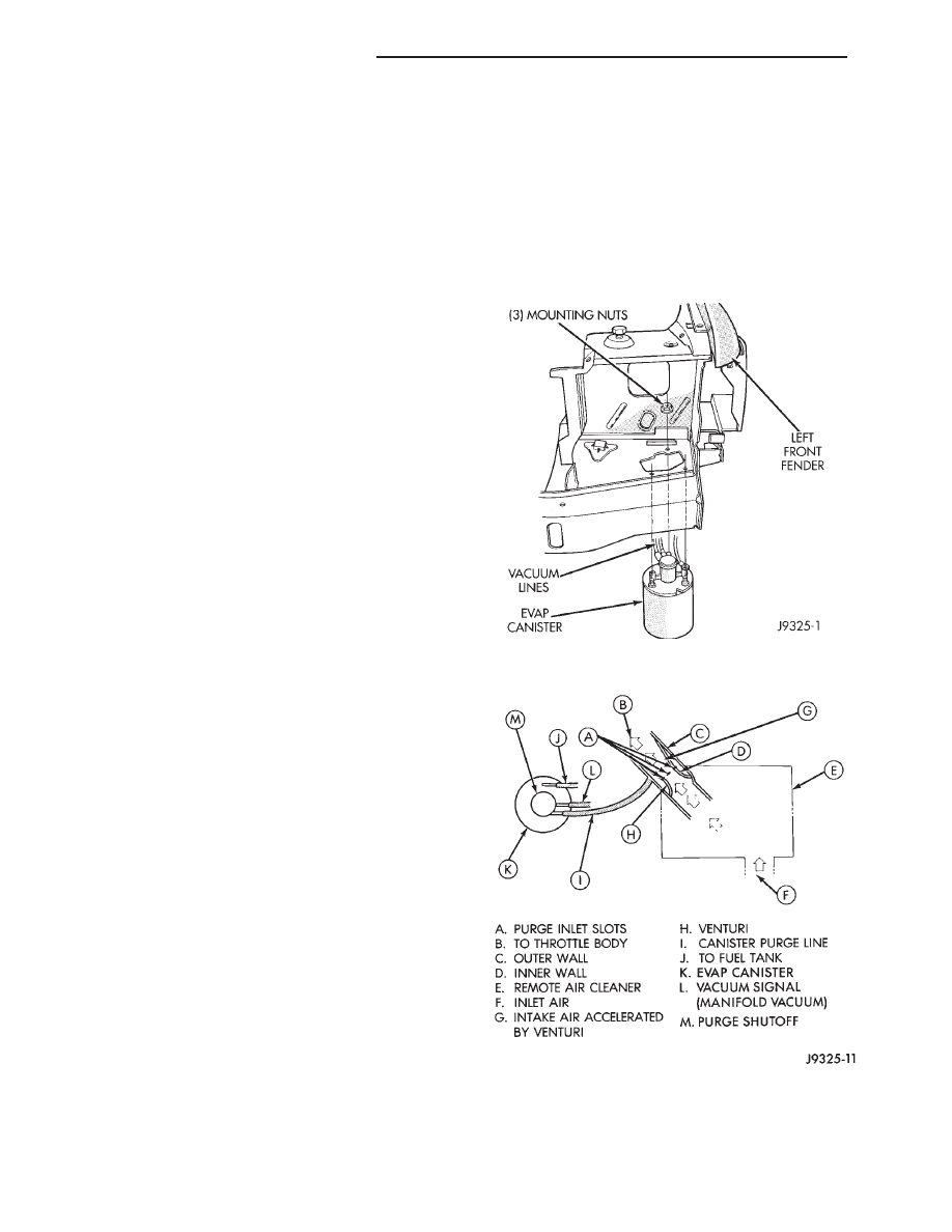
EVAP CANISTER
A sealed, maintenance free, EVAP canister is used
on all vehicles. The EVAP canister is located in the
left front corner of vehicle below the left front head-
lamp (Fig. 1). The EVAP canister is filled with gran-
ules of an activated carbon mixture. Fuel vapors en-
tering the EVAP canister are absorbed by the
charcoal granules.
Operation of the EVAP canister is different between
the 4.0L six-cylinder engine and the 5.2L V-8 engine.
Refer to the following Canister Operation.
CANISTER OPERATION—4.0L ENGINE
The EVAP canister is equipped with a vacuum con-
trolled purge shutoff switch (orifice) (Fig. 2) that con-
trols canister purge operation. The switch is open
when manifold vacuum is applied to it. When the
engine is operating, the EVAP canister purge function
draws fresh air through the top of the canister. This
causes the stored vapors to be drawn out of the
canister and into the airstream in the air cleaner
snorkel (Fig. 2).
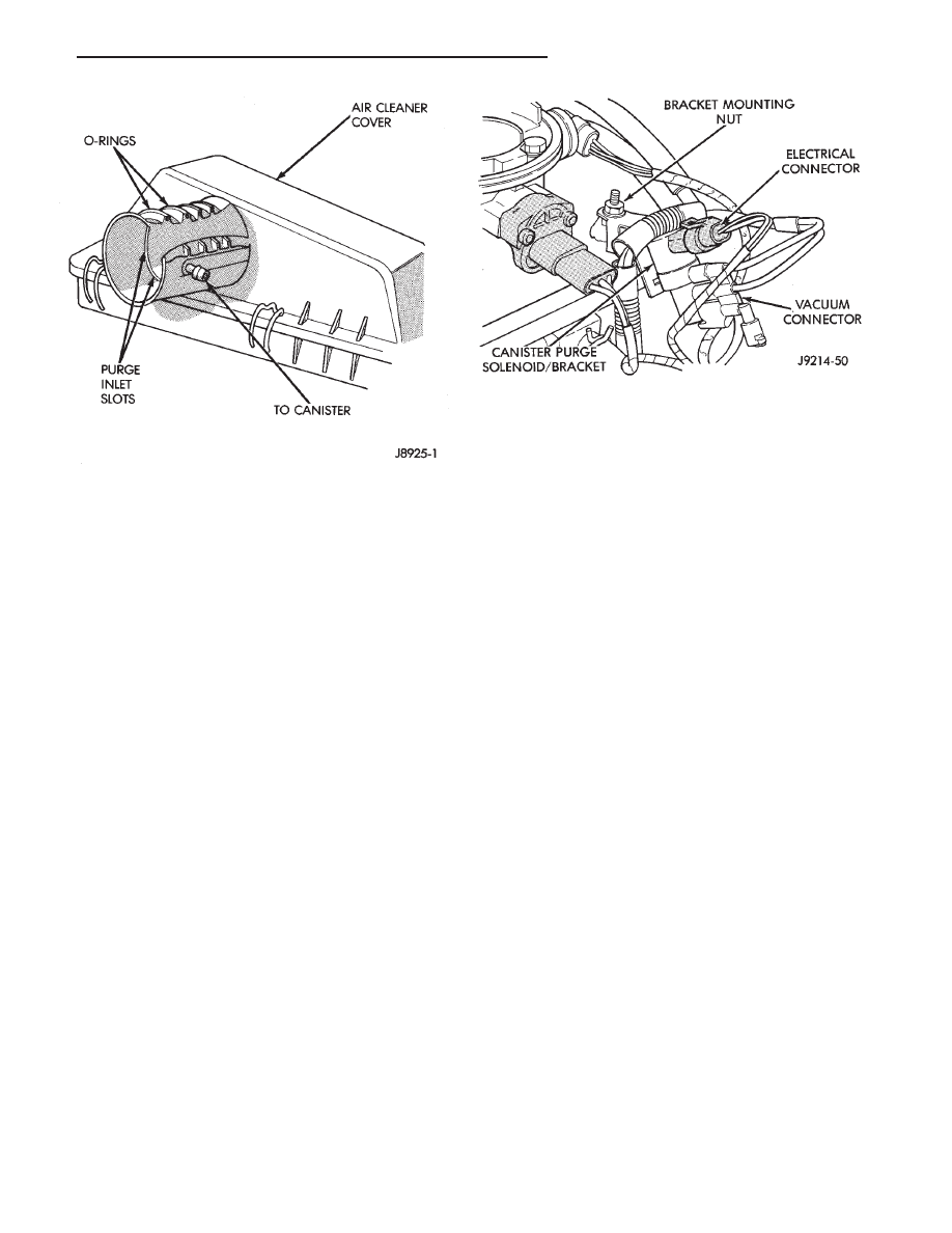
The air cleaner contains a venturi in the air cleaner
cover used as a purge line vacuum source (Fig. 3).
The venturi effect increases the speed of the intake
air flowing by the slots in the venturi wall. This
creates a low pressure area around the slots. When
the purge shutoff switch is open, vapors from the
canister are drawn through slots and into the air-
stream flowing through the venturi (Fig. 3). The va-
pors pass through the intake manifold into the engine
combustion chambers where they are consumed dur-
ing engine combustion.
Fig. 1 EVAP Canister Location
Fig. 2 EVAP System—4.0L Engine—Typical
25 - 4
EMISSION CONTROL SYSTEMS
Z
CANISTER OPERATION—5.2L ENGINE
Fuel tank pressure vents into the EVAP canister.
Fuel vapors are temporarily held in the canister until
they can be drawn into the intake manifold. The
EVAP canister purge solenoid allows the EVAP canis-
ter to be purged at predetermined times and at cer-
tain engine operating conditions. For more informa-
tion, refer to the following EVAP Canister Purge
Solenoid—5.2L Engine.
EVAP CANISTER PURGE SOLENOID—5.2L ENGINE
The EVAP canister purge solenoid is used with the
5.2L (V-8) engine only.
Vacuum for the EVAP canister is controlled by the
EVAP Canister Purge Solenoid (Fig. 4). The solenoid
is operated by the powertrain control module (PCM).
The PCM regulates the solenoid by switching the
ground circuit on and off based on engine operating
conditions. When energized, the solenoid prevents
vacuum from reaching the EVAP canister. When not
energized,
the
solenoid
allows
vacuum
to
flow
through to the EVAP canister.
During warm-up and for a specified time period
after hot starts, the PCM grounds the EVAP canister
purge solenoid causing it to energize. This will pre-
vent vacuum from reaching the EVAP canister valve.
When the engine reaches an operating temperature of
approximately 27°C (80°F) and a time delay interval
of about 100 seconds has occurred, the PCM removes
the ground to solenoid. The de-energized solenoid al-
lows vacuum to flow to the EVAP canister and purge
fuel vapors through the intake manifold.
The EVAP canister purge solenoid will also be ener-
gized during certain idle conditions in order to update
the fuel delivery calibration.
FUEL TANK FILLER TUBE CAP
The fuel tank filler tube cap incorporates a two-way
relief valve that is closed to atmosphere during nor-
mal operating conditions. The relief valve used in fuel
filler caps of all models is calibrated at a pressure of
10 kPa (1.5 psi) or a vacuum of 6 kPa (1.8 in. Hg).
When the pressure or vacuum is relieved, the valve
returns to the normally closed position.
CAUTION: The fuel filler cap must be removed prior
to disconnecting any fuel system component.
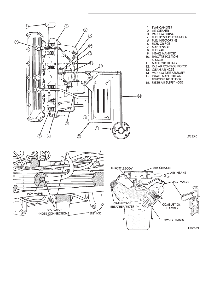
CRANKCASE VENTILATION SYSTEM—4.0L ENGINE
The 4.0L engine is equipped with a Crankcase Ven-
tilation (CCV) system (Fig. 5). The CCV system per-
forms the same function as a conventional PCV sys-
tem, but does not use a vacuum controlled valve.
A molded vacuum tube connects manifold vacuum
to top of cylinder head cover at dash panel end. The
vacuum tube contains a fixed orifice (Fig. 5) of a
calibrated size. It meters the amount of crankcase
vapors drawn out of the engine.
A fresh air supply hose from the air cleaner (Fig. 5)
is connected to front of cylinder head (valve) cover.
When the engine is operating, fresh air enters the
engine and mixes with crankcase vapors. Manifold
vacuum draws the vapor/air mixture through the
fixed orifice and into the intake manifold. The vapors
are then consumed during engine combustion.
POSITIVE CRANKCASE VENTILATION SYSTEM
DESCRIPTION/OPERATION
The 5.2L V-8 engine is equipped with a closed posi-
tive crankcase ventilation (PCV) system (Fig. 6).
This system consists of a crankcase PCV valve
mounted on the cylinder head cover with a hose ex-
tending from the valve to the intake manifold.
Fig. 3 Air Cleaner Venturi—4.0L Engine—Typical
Fig. 4 Purge Solenoid—5.2L Engine—Typical
Z
EMISSION CONTROL SYSTEMS
25 - 5
A closed engine crankcase breather/filter, with a
hose connecting it to the air cleaner housing, pro-
vides the source of air for system.
The positive crankcase ventilation (PCV) system oper-
ates by engine intake manifold vacuum (Fig. 7). Fil-
tered air is routed into the crankcase through the air
cleaner hose and crankcase breather/filter. This forces
crankcase vapors through the PCV valve. It is then
drawn into the intake manifold. Here it becomes part of
the calibrated air/fuel mixture to be consumed in the
combustion chamber. The PCV system constantly venti-
lates the crankcase to help prevent sludge formation
and vapors from entering the atmosphere.
POSITIVE CRANKCASE VENTILATION (PCV)
VALVE
The PCV valve contains a spring loaded plunger.
This plunger meters the amount of crankcase vapors
routed into the combustion chamber based on intake
manifold vacuum.
Fig. 5 CCV System—4.0L Engine—Typical
Fig. 6 PCV Valve/Hose—5.2L Engines
Fig. 7 Typical Closed Crankcase Ventilation System
25 - 6
EMISSION CONTROL SYSTEMS
Z
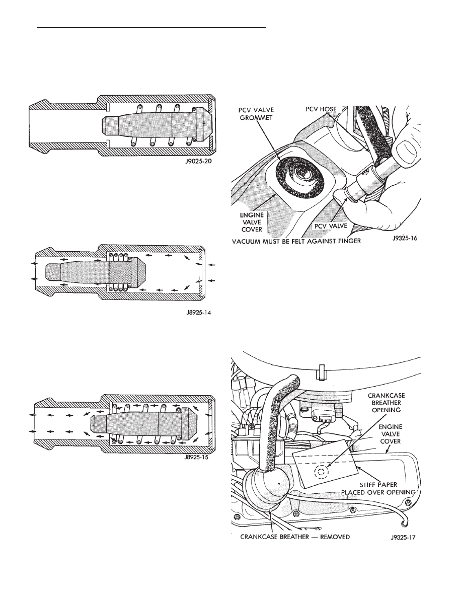
When the engine is not operating, or during an
engine popback, the spring forces the plunger back
against the seat. This will prevent vapors from flow-
ing through the valve (Fig. 8).
During periods of high manifold vacuum, such as
idle or cruising speeds, vacuum is sufficient to com-
pletely compress spring. It will then pull the plunger
to the top of the valve (Fig. 9). In this position there is
minimal vapor flow through the valve.
During periods of moderate manifold vacuum, the
plunger is only pulled part way back from inlet. This
results in maximum vapor flow through the valve
(Fig. 10).
INSPECTION AND SERVICE PROCEDURE
(1) With engine idling, remove the PCV valve from
cylinder head cover. If the valve is not plugged, a
hissing noise will be heard as air passes through the
valve. Also, a strong vacuum should be felt at the
valve inlet (Fig. 11).
(2) Install the PCV valve. Remove the crankcase
breather/filter. Hold a piece of stiff paper, such as a
parts tag, loosely over the opening of crankcase
breather/filter at the cylinder head (valve) cover (Fig.
12).
(3) The paper should be drawn against the opening
in the cylinder head (valve) cover with noticeable
force. This will be after allowing approximately one
minute for crankcase pressure to reduce.
Fig. 8 Engine Off or Engine PopBack—No Vapor
Flow
Fig. 9 High Intake Manifold Vacuum—Minimal Vapor
Flow
Fig. 10 Moderate Intake Manifold
Vacuum—Maximum Vapor Flow
Fig. 11 Check Vacuum at PCV Valve—Typical
Fig. 12 Check Vacuum at Crankcase Breather
Opening—Typical
Z
EMISSION CONTROL SYSTEMS
25 - 7
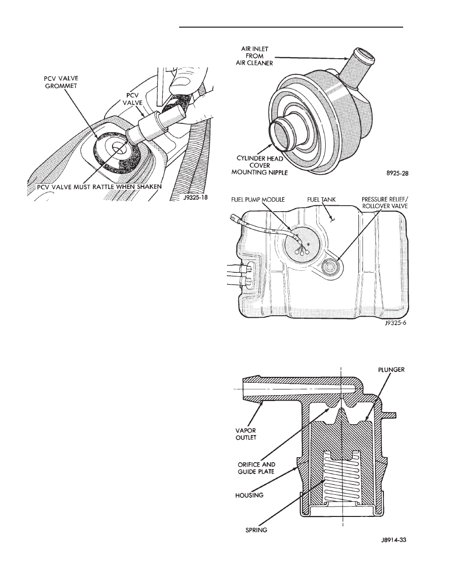
cylinder head (valve) cover. The valve should rattle
when shaken (Fig. 13).
Replace the PCV valve and retest the system if it
does not operate as described in the preceding tests.
Do not attempt to clean the old PCV valve.
(5) If the paper is not held against the opening in
cylinder head (valve) cover after new valve is in-
stalled, the PCV valve hose may be restricted and
must be replaced. The passage in the intake manifold
must also be checked and cleaned.
(6) To clean the intake manifold fitting, turn a 1/4
inch drill (by hand) through the fitting to dislodge
any solid particles. Blow out the fitting with shop air.
If necessary, use a smaller drill to avoid removing any
metal from the fitting.
CRANKCASE BREATHER/FILTER—5.2L ENGINES
The crankcase breather/filter is used with the 5.2L
V-8 engine only.
The crankcase breather/filter (Fig. 14) is located on
the engine valve cover. It must be kept clean and
lubricated. At the recommended interval, remove the
filter and wash it thoroughly in kerosene, or similar
solvent. Lubricate or wet the filter by inverting it and
filling with SAE 30 engine oil. Filter must then be
thoroughly drained. More frequent service may be
necessary for vehicles operated extensively on short
run, stop and go, or extended engine idle service.
The filter must be replaced at correct intervals.
Refer to Lubrication and Maintenance, Group 0.
PRESSURE RELIEF/ROLLOVER VALVE
These vehicles are equipped with a combination fuel
tank pressure relief and rollover valve (Fig. 15). This
dual function valve will relieve fuel tank pressure and
also prevent fuel flow through the fuel tank vent hoses
in the event of an accidental vehicle rollover.
The valve incorporates a pressure relief mechanism
(Fig. 16) that releases fuel tank pressure when the pres-
sure increases above the calibrated sealing value. Refer
to the Fuel Tank section of Group 14, Fuel Systems for
removal and installation procedures.
Fig. 13 Shake PCV Valve—Typical
Fig. 14 Crankcase Breather/Filter—5.2L Engine
Fig. 15 Pressure Relief/Rollover Valve Location
Fig. 16 Pressure Relief/Rollover Valve Operation
25 - 8
EMISSION CONTROL SYSTEMS
Z
EXHAUST EMISSION CONTROLS
INDEX
page
page
Air Cleaner
. . . . . . . . . . . . . . . . . . . . . . . . . . . . . . 9
Exhaust Gas Recirculation System—5.2L Engine
. . 9
Oxygen (O
2
) Sensor
. . . . . . . . . . . . . . . . . . . . . . . 11
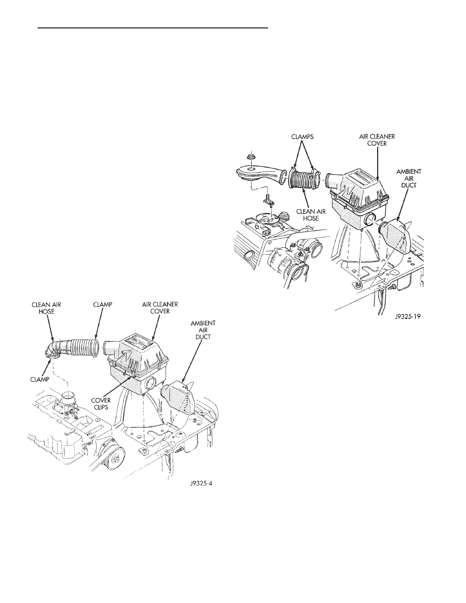
AIR CLEANER
The air cleaner used on all models (Figs. 1 or 2) is
open to ambient air. The blend air door and vacuum
motor that was used on 4.0L engines of previous
model years to supply heated air, is no longer used.
The air cleaner housing assembly contains the engine
air filter.
The Powertrain Control Module (PCM) monitors air
temperature in the intake manifold through the In-
take Manifold Air Temperature sensor. The PCM ad-
justs injector pulse width and ignition timing to com-
pensate
for
intake
air
temperature.
Refer
to
Powertrain Control Module (PCM) in Group 14, Fuel
System for more information.
Refer to the Component Removal/Installation sec-
tion of this group for removal and installation proce-
dures.
EXHAUST GAS RECIRCULATION SYSTEM—5.2L
ENGINE
GENERAL INFORMATION
The Exhaust Gas Recirculation (EGR) System is
used with the 5.2L engine only.
The EGR system reduces oxides of nitrogen (NOx)
in the engine exhaust and helps prevent spark knock.
This is accomplished by allowing a predetermined
amount of hot exhaust gas to recirculate and dilute
the incoming fuel/air mixture. This dilution reduces
peak flame temperature during combustion.
The system consists of an intake manifold mounted
EGR valve (Fig. 3) and connecting hoses. The vacuum
to the EGR is controlled by the Electric EGR Trans-
ducer (EET) (Figs. 3 and 4). The EET is a dual
electric/vacuum function switch. It is controlled by
the powertrain control module (PCM).
EGR OPERATION—5.2L ENGINE
The Electric Exhaust Gas Recirculation Transducer
(EET) is a back pressure transducer and an electric
vacuum solenoid combined into a single unit (Figs. 3
and 4). The vacuum solenoid portion of the EET
receives its electrical signal from the powertrain con-
trol module (PCM). Using this signal, the solenoid
regulates the vacuum flowing through to the trans-
ducer portion of the EET. The back pressure trans-
ducer measures the amount of exhaust gas back pres-
sure on the exhaust side of the EGR valve. It then
varies
the
strength
of
the
vacuum
signal
ap-
Fig. 1 Air Cleaner—4.0L Engine
Fig. 2 Air Cleaner—5.2L Engine
Z
EMISSION CONTROL SYSTEMS
25 - 9
plied to the EGR valve. The transducer uses this back
pressure signal to provide the correct amount of ex-
haust gas recirculation under all conditions.
The vacuum supply for the EGR valve is controlled
by the EET. The electrical solenoid portion of the EET
is controlled by the powertrain control module (PCM).
The PCM monitors engine coolant temperature and
other operating conditions to determine when EGR
operation is desired. Refer to Open Loop/Closed Loop
Modes of Operation in Group 14, Fuel Systems for a
description of EGR solenoid operation based on en-
gine operating conditions.
If the electrical connector to the EET is dis-
connected, or the electrical signal is lost, the
EGR valve will operate at all times. This results
in poor engine performance and reduced driveability
during certain operating conditions.
Vacuum flows between the solenoid portion of the
EET and the transducer portion of the EET. This
happens only when the solenoid is not electrically
energized. The transducer is connected to the EGR
valve by a vacuum hose and a back pressure hose.
The transducer is controlled by exhaust back pressure
and is ported to the exhaust manifold through a hose
connecting it to the bottom of the EGR valve.
Vacuum will be supplied to the EGR valve and EGR
operation will begin when:
• The electrical solenoid portion of the EET is not
energized.
• The engine back pressure entering the EGR valve
inlet is strong enough to close the transducer bleed
valve.
If back pressure is not strong enough to close the
transducer bleed valve, the transducer will bleed off
the vacuum preventing EGR operation.
When the electrical solenoid portion of the EET is
de-energized by the powertrain control module (PCM),
vacuum flows to the transducer. The transducer is con-
nected to the engine exhaust system by a small hose
that connects to the base of the EGR valve.
The vacuum section of the transducer is controlled
by exhaust system back pressure. When back pres-
sure is high enough it will close a bleed valve in the
transducer allowing vacuum to actuate the EGR
valve. If back pressure does not close the bleed valve,
vacuum will be bled off.
For more information, refer to the Multi-Port Fuel
Injection section of Group 14, Fuel Systems for 5.2L
engines.
EGR SYSTEM ON-BOARD DIAGNOSTICS
(CALIFORNIA VEHICLES ONLY)
The powertrain control module (PCM) performs an
On-Board Diagnostic (OBD) check of the EGR system
on all California vehicles. The diagnostic system uses
the Electric EGR Transducer (EET) for the system
tests.
The OBD check activates only during selected
engine/driving conditions. When the conditions are
met, the PCM energizes the EET solenoid to disable
the EGR. The PCM checks for a change in the oxygen
sensor signal. If the air-fuel mixture goes lean, the
PCM will attempt to enrichen the mixture. The PCM
registers a Diagnostic Trouble Code (DTC) if the EGR
system has failed or degraded. After registering a
DTC, the PCM turns the Malfunction Indicator
Lamp (MIL) on. (The Malfunction Indicator Lamp
was formerly referred to as the Check Engine Lamp).
The Malfunction Indicator Lamp indicates the need
for immediate service.
If a malfunction is indicated by the Malfunction
Indicator Lamp and a DTC for the EGR system was
set, check for proper operation of EGR system. Use
the following: System Test, EGR Gas Flow Test and
EGR Diagnosis Chart.
If the EGR system tests properly, check the system
using the DRB II scan tool. For use of the DRB II,
refer to the appropriate Powertrain Diagnostics Pro-
cedure service manual.
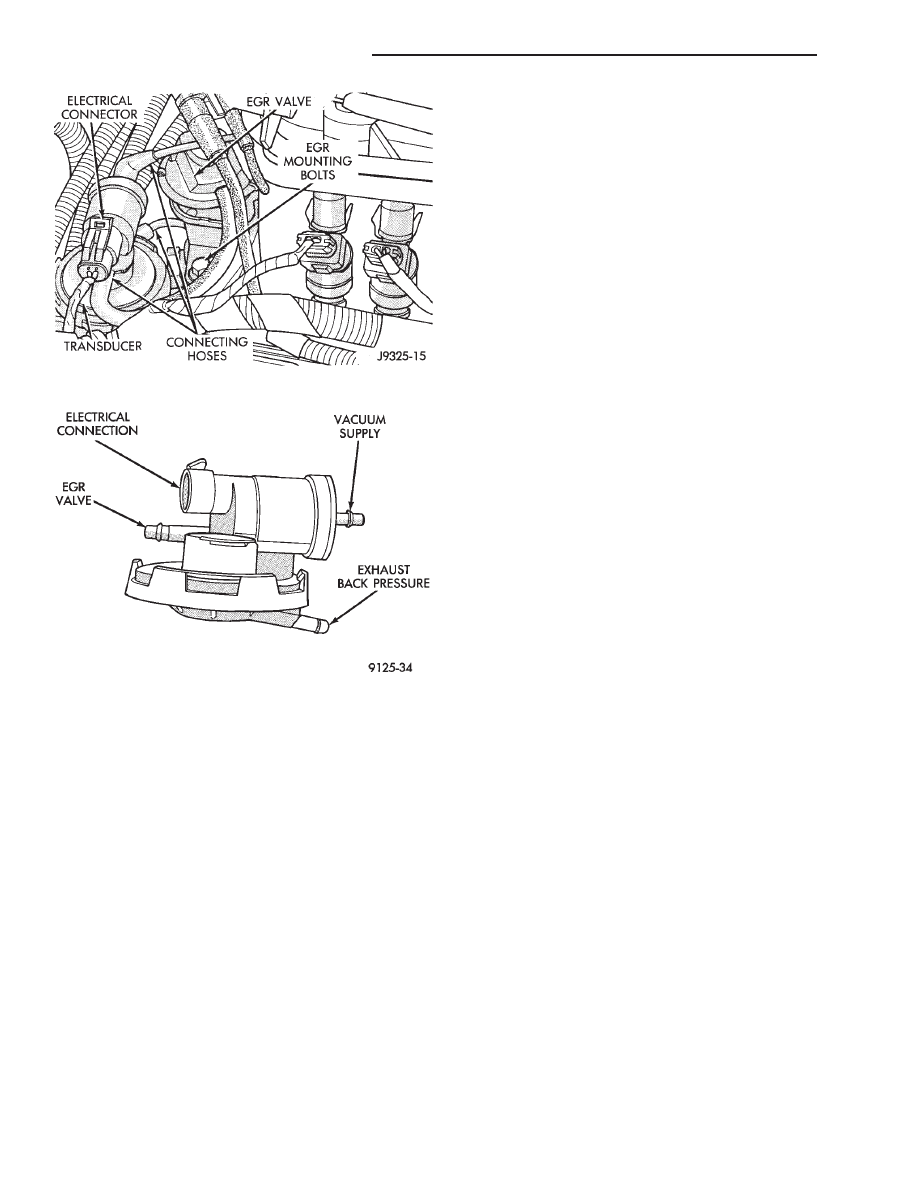
Fig. 3 EGR System—5.2L Engine
Fig. 4 Electric EGR Transducer (EET)—5.2L Engine
25 - 10
EMISSION CONTROL SYSTEMS
Z

EGR SYSTEM SERVICE—5.2L ENGINE
A malfunctioning EGR system can cause engine
spark knock, sags or hesitation, rough idle, engine
stalling and poor driveability. To be sure of proper
operation of the EGR system, inspect all passages for
blockage. Check moving parts for binding. Inspect the
complete system for leaks. Replace system compo-
nents or hoses that are leaking.
Inspect all hose connections between throttle body,
intake manifold, EGR valve and EGR purge solenoid.
Replace any vacuum harness components that are
leaking or damaged.
Refer to EGR Control System Test and EGR Gas
Flow Test to check EGR System operation.
EGR GAS FLOW TEST—5.2L ENGINE
(1) Disconnect hose from EGR valve and connect a
hand vacuum pump to EGR valve nipple. Apply a
minimum of 12 inches vacuum the valve.
(2) The engine should now idle roughly or stall. If
this occurs, the valve is performing correctly. Proceed
to Electric EGR Transducer Test.
(3) If the engine idle speed did not change, remove the
EGR valve and inspect the valve and the exhaust pas-
sage in the manifold for blockage. Repair as necessary. If
blockage is not present, replace the EGR valve.
ELECTRIC EGR TRANSDUCER (EET)—5.2L EN-
GINE
TESTING ELECTRIC SOLENOID PORTION OF TRANSDUCER
(1) Bring the engine to normal operating tempera-
ture. Operate at idle speed. Test the EET as follows:
(2) Check vacuum at EET vacuum source. Discon-
nect the hose and attach a vacuum gauge to it.
(3) Vacuum should be a minimum of 15 inches:
• If vacuum is low, check the line for kinks, twists, or
a loose connection at vacuum connector or intake
manifold.
• If vacuum is correct, remove gauge. Connect the
vacuum line and proceed to next step.
(4) Check EET operation using the appropriate
Powertrain Diagnostic Procedures service manual.
Refer to this manual for use of the DRB II scan tool
and repair EET as necessary.
TESTING VACUUM PORTION OF TRANSDUCER
(1) Disconnect the EET vacuum lines, back pres-
sure line and electrical connector. Remove transducer.
(2) Plug the EET EGR valve port.
(3) Apply 1-2 pounds air pressure to exhaust back
pressure port. Air pressure can be supplied with a
hand operated air pump or compressed air (regulated
to correct psi).
(4) Apply a minimum of 12 inches of vacuum to
vacuum supply port.
Replace the EET if it will not hold vacuum.
For electrical tests of the EET and its circuitry,
refer to the appropriate Powertrain Diagnostic Proce-
dures service manual and use the DRB II scan tool.
OXYGEN (O
2
) SENSOR
For
description,
operation,
diagnosis
and
removal/installation procedures of the O
2
sensor, refer
to Group 14, Fuel Systems.
Z
EMISSION CONTROL SYSTEMS
25 - 11
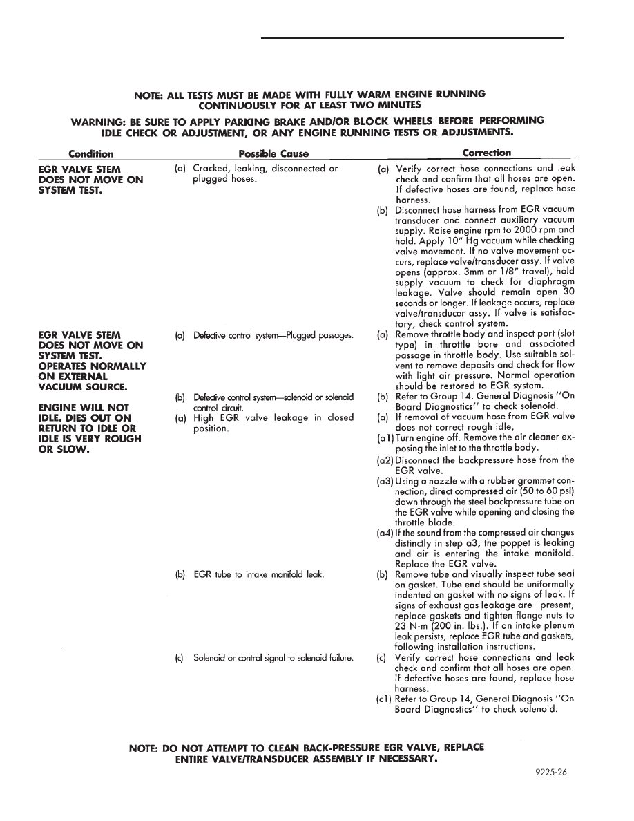
EGR DIAGNOSIS CHART—5.2L ENGINE
25 - 12
EMISSION CONTROL SYSTEMS
Z
COMPONENT REMOVAL/INSTALLATION
INDEX
page
page
Air Cleaner Housing
. . . . . . . . . . . . . . . . . . . . . . . 13
Air Filter
. . . . . . . . . . . . . . . . . . . . . . . . . . . . . . . 14
Coolant Temperature Sensor
. . . . . . . . . . . . . . . . 14
EGR Tube—5.2L Engine
. . . . . . . . . . . . . . . . . . . 15
EGR Valve—5.2L Engine
. . . . . . . . . . . . . . . . . . . 14
Electric EGR Transducer (EET)—5.2L Engine
. . . . 16
Evap Canister
. . . . . . . . . . . . . . . . . . . . . . . . . . . 16
EVAP Canister Purge Solenoid
. . . . . . . . . . . . . . . 16
Fuel Tank Filler Tube Cap
. . . . . . . . . . . . . . . . . . 17
Oxygen (O
2
) Sensor . . . . . . . . . . . . . . . . . . . . . . . 17
Powertrain Control Module (PCM) . . . . . . . . . . . . . 17
Pressure Relief/Rollover Valve
. . . . . . . . . . . . . . . 17
AIR CLEANER HOUSING
REMOVAL
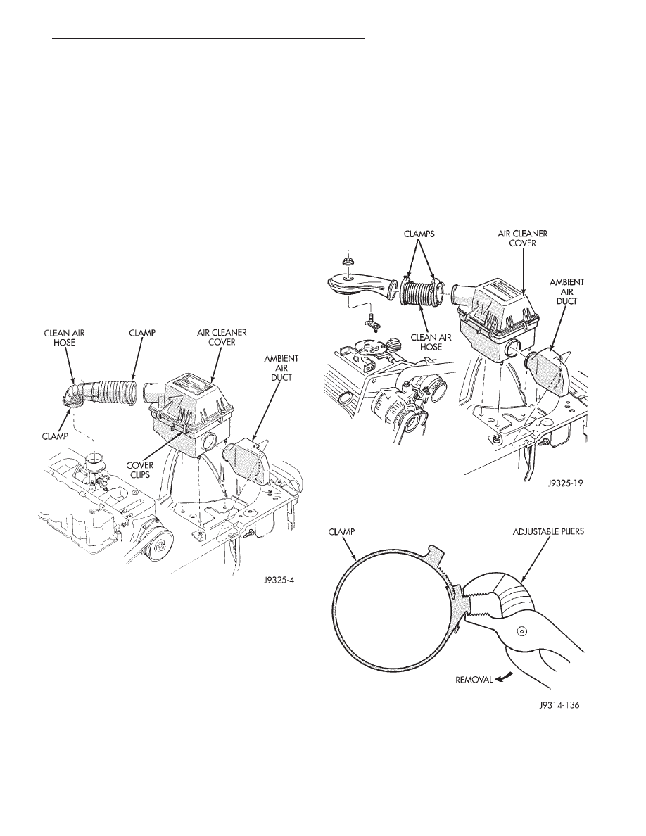
(1) Unlock clean air hose clamp (Figs. 1 or 2) at air
cleaner cover. To unlock the clamp, attach adjustable
pliers to clamp and rotate pliers as shown in figure 3.
Remove clean air hose at cover.
(2) Remove crankcase breather/filter hose at air
cleaner cover.
(3) From under vehicle, remove three housing nuts
(Figs. 1 or 2).
(4) Release the air cleaner housing from the ambi-
ent air duct and remove housing from vehicle.
INSTALLATION
(1) Position air cleaner housing to body and ambi-
ent air duct (Figs. 1 or 2).
(2) Install three nuts and tighten to 10 N
Im (93 in.
lbs.) torque.
(3) Install crankcase breather/filter hose to cover.
(4) Install clamp to cover. Compress the clamp
snugly with adjustable pliers as shown in figure 4.
Fig. 1 Air Cleaner—4.0L Engine
Fig. 2 Air Cleaner—5.2L Engine
Fig. 3 Clamp Removal
Z
EMISSION CONTROL SYSTEMS
25 - 13
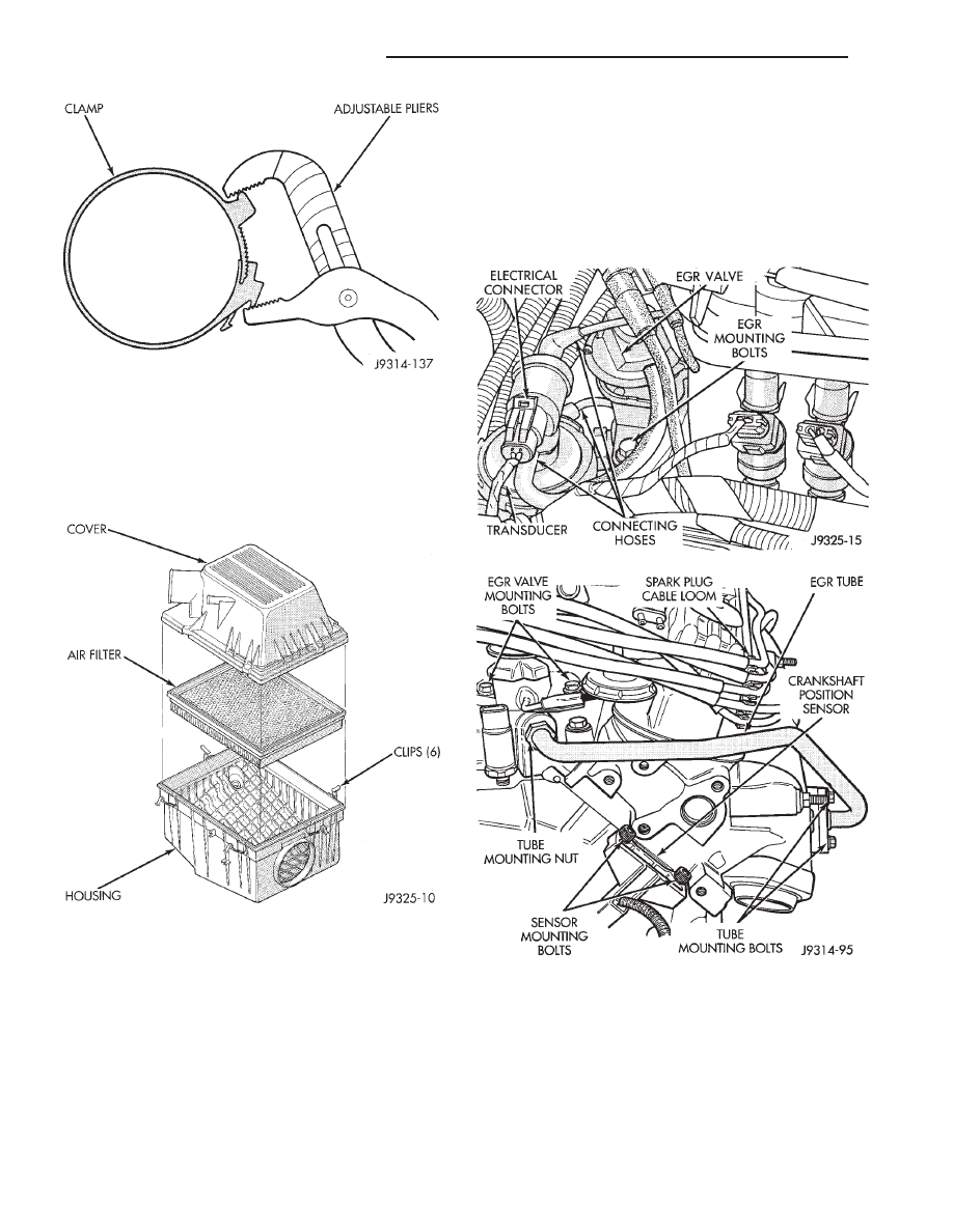
AIR FILTER
REMOVAL/INSTALLATION
(1) Pry back the six clips retaining the air cleaner
cover to the air cleaner housing (Fig. 5).
(2) Lift the cover up and position to the side.
(3) Remove air filter.
(4) Clean the inside of air cleaner housing before
installing new filter.
(5) Reverse the preceding operation for installation.
Be sure the air cleaner cover is properly seated to air
cleaner housing.
COOLANT TEMPERATURE SENSOR
For
description,
operation,
diagnosis
and
removal/installation procedures of the engine coolant
temperature sensor, refer to Group 14, Fuel Systems.
EGR VALVE—5.2L ENGINE
REMOVAL
The EGR valve and the Electric EGR Transducer
(EET) are serviced as one unit on the 5.2L engine.
(1) Disconnect
vacuum
hose
to
EGR
valve/transducer assembly. Note position of hoses
(Fig. 6) on the EGR valve and transducer for easier
installation.
(2) Remove EGR mounting bolts (Figs. 6 or 7).
(3) Remove EGR valve and gasket. Discard old gas-
ket. Clean intake manifold mating surface and check
for cracks.
INSTALLATION
(1) Place new EGR gasket on intake manifold.
(2) Install EGR valve. Tighten mounting bolts to 23
N
Im (200 in. lbs.) torque.
Fig. 4 Clamp Installation
Fig. 5 Air Filter Removal/Installation
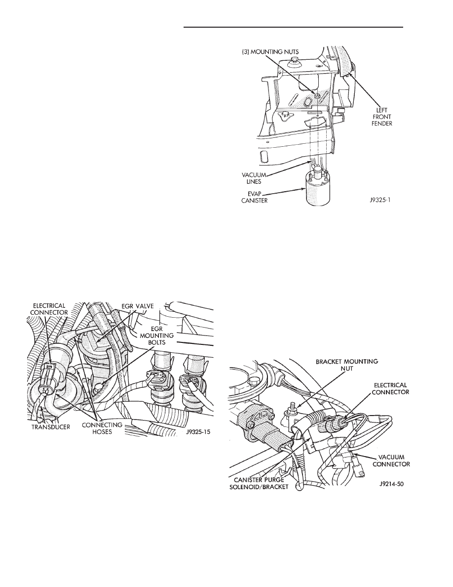
Fig. 6 EGR Valve Hoses—5.2L Engines
Fig. 7 EGR Valve Mounting Bolts—5.2L Engines
25 - 14
EMISSION CONTROL SYSTEMS
Z
(3) Connect vacuum hose to valve/transducer as-
sembly.
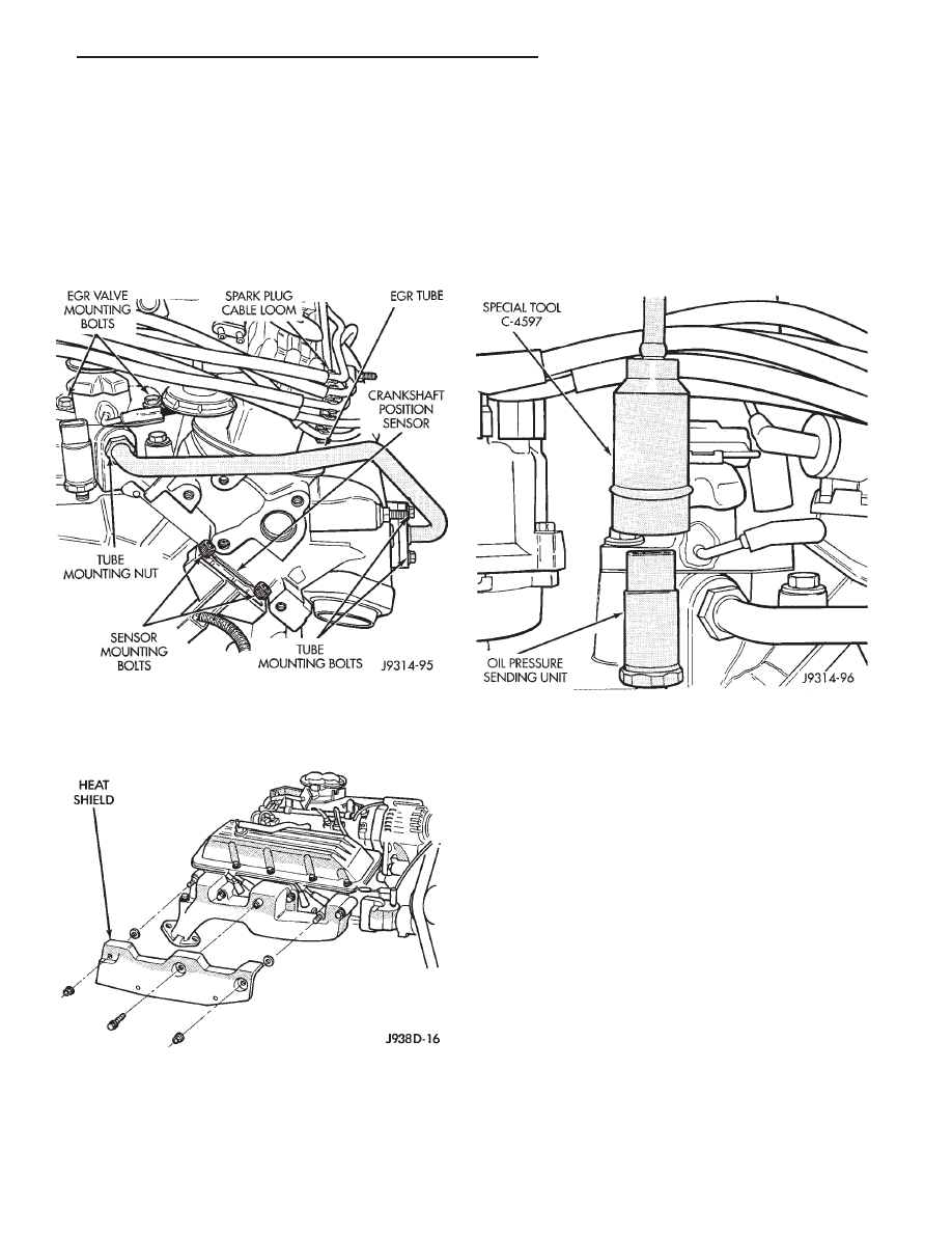
EGR TUBE—5.2L ENGINE
REMOVAL
(1) Remove the spark plug cable loom and spark
plug cables from valve cover mounting stud at rear of
right valve cover (Fig. 8). Position spark plug cables
to top of valve cover.
(2) Remove the right exhaust manifold heat shield
nuts/bolts and remove heat shield (Fig. 9).
(3) Disconnect 2 hoses at Exhaust Gas Recircula-
tion (EGR) valve. Note position of hoses at EGR valve
before removal.
(4) Disconnect electrical connector and hoses at
electric EGR transducer (EET). Note position of hoses
at EET before removal.
(5) Remove 2 EGR valve mounting bolts (Fig. 8)
and remove EGR valve. Discard old EGR gasket.
(6) Disconnect electrical connector at engine oil
pressure sending unit.
(7) To prevent damage to oil pressure sending unit,
a special tool, such as number C-4597 must be used
(Fig. 10). Remove sending unit from engine.
(8) Loosen EGR tube mounting nut at intake mani-
fold (Fig. 8).
(9) Remove 2 EGR tube mounting bolts at exhaust
manifold (Fig. 8) and remove EGR tube. Discard old
gasket at exhaust manifold.
(10) Remove EGR tube from vehicle.
INSTALLATION
(1) Clean the EGR tube and exhaust manifold (at
EGR tube mounting point) of any old gasket material.
(2) Install a new gasket to exhaust manifold end of
EGR tube and install EGR tube to both manifolds.
Tighten tube mounting nut at intake manifold.
Tighten 2 mounting bolts at exhaust manifold to 23
N
Im (204 in. lbs.) torque.
(3) Coat the threads of the oil pressure sending
unit with thread sealant. Do not allow any of the
thread sealant to get into the sending unit opening, or
the opening at the engine. Install sending unit to
engine and tighten to 14 N
Im (130 in. lbs.) torque.
Install electrical connector to sending unit.
Fig. 8 EGR Tube—5.2L Engine
Fig. 9 Exhaust Manifold Heat Shield—5.2L Engine
Fig. 10 Oil Pressure Sending Unit—Removal/
Installation
Z
EMISSION CONTROL SYSTEMS
25 - 15
(4) Clean the intake manifold and EGR valve of
any old gasket material.
(5) Install a new EGR valve gasket at intake mani-
fold.
(6) Install EGR valve to intake manifold. Tighten 2
EGR bolts to 23 N
Im (200 in. lbs.) torque.
(7) Position EET and install its electrical connector.
Connect hoses between EGR valve and EET. Connect
hose between main vacuum harness and EET.
(8) Install spark plug cable loom and spark plug
cables to valve cover mounting stud.
(9) Install heat shield at right exhaust manifold.
ELECTRIC EGR TRANSDUCER (EET)—5.2L ENGINE
The EGR valve and the EET are serviced as one
unit on the 5.2L engine. Also refer to EGR valve
removal/installation.
REMOVAL
(1) Disconnect wiring connector at EET (Fig. 11).
(2) Disconnect hoses at EET. Note position of hoses
for easier installation.
(3) Remove EET from engine.
INSTALLATION
(1) Position EET to engine and connect hoses.
(2) Connect wiring connector.
EVAP CANISTER
REMOVAL
(1) Remove the grill. Refer to group 23, Body.
(2) Remove the front bumper/fascia assembly. Refer
to group 23, Body.
(3) Disconnect vacuum lines at canister.
(4) Remove the three canister mounting nuts (Fig.
12).
(5) Lower the canister through bottom of vehicle.
INSTALLATION
(1) Position canister to body.
(2) Install canister mounting nuts. Tighten nuts to
6 N
Im (55 in. lbs.) torque.
(3) Connect vacuum lines.
(4) Install the front bumper/fascia assembly and
grill. Refer to Group 23, Body.
EVAP CANISTER PURGE SOLENOID
REMOVAL—5.2L ENGINE
(1) Remove air duct at throttle body.
(2) Disconnect wiring connector at solenoid (Fig.
13).
(3) Disconnect vacuum harness at solenoid (Fig.
13).
(4) Remove solenoid and its support bracket from
intake manifold.
Fig. 11 Electric EGR Transducer—5.2L Engine
Fig. 12 EVAP Canister Location
Fig. 13 EVAP Canister Purge Solenoid—5.2L Engine
25 - 16
EMISSION CONTROL SYSTEMS
Z

(5) Remove EVAP canister purge solenoid from en-
gine.
INSTALLATION
(1) Install EVAP canister purge solenoid and its
mounting bracket to intake manifold.
(2) Connect vacuum harness and wiring connector.
(3) Install air duct to throttle body.
FUEL TANK FILLER TUBE CAP
If replacement of the fuel filler tube cap is neces-
sary, it must be replaced with an identical cap to be
sure of correct system operation.
OXYGEN (O
2
) SENSOR
For
description,
operation,
diagnosis
and
removal/installation procedures of the O
2
sensor, refer
to Group 14, Fuel Systems.
POWERTRAIN CONTROL MODULE (PCM)
For removal and installation procedures, refer to
Group 14, Fuel Systems.
PRESSURE RELIEF/ROLLOVER VALVE
For removal and installation procedures, refer to
the Fuel Tank section of Group 14, Fuel Systems.
Z
EMISSION CONTROL SYSTEMS
25 - 17

Document Outline
- EMISSION CONTROL SYSTEMS
- GENERAL INFORMATION
- EVAPORATIVE EMISSION CONTROLS
- EXHAUST EMISSION CONTROLS
- COMPONENT REMOVAL/ INSTALLATION
Wyszukiwarka
Podobne podstrony:
96ZJ 25 EMISSION CONTROL SYSTEMS
10 Emission control system
07 emission control system
10 Emission control system
07 emission control system
10 Emission control system
Group 025 Emission Control Systems
93ZJ Secc 8H Vehicle Speed Control System
93ZJ Secc 11 Exhaust System and Intake Manifold
93ZJ Secc 8F Audio Systems
93ZJ Secc 8A Electrical Systems
93ZJ Secc 8M Restraint Systems
93ZJ Secc 8Q Vehicle Theft Security System
93ZJ Secc 8K Windshield Wiper and Washer Systems
93ZJ Secc 8U Chime Buzzer Warning Systems
Control System Toolbox
10 Engine Control System
6J Emissions Controls
więcej podobnych podstron