INSTRUCTIONS AND PARTS LIST AB-10/2007
Supersedes Instructions & Parts List AB-5/2006
WARNING: Spray materials may be harmful if inhaled or
allowed to come into contact with the skin or eyes. Consult
the product label and Material Safety Data Sheet supplied
for the spray material. Follow all safety precautions.
CAUTION: Well Ventilated Area Required to remove
fumes, dust or overspray. Secure airhose to Airbrush
with V-62 Wrench for safety and to prevent air leaks.
M a x i m u m A i r P r e s s u r e 5 0 P . S . I .
AB
(Fine Art) Airbrush
Customer Note: New “AB” Airbrushes are factory inspected for
immediate use.
The “AB” Airbrush maintenance and replacement parts
instructions are for Airbrushes that have been used extensively
and require refurbishing.
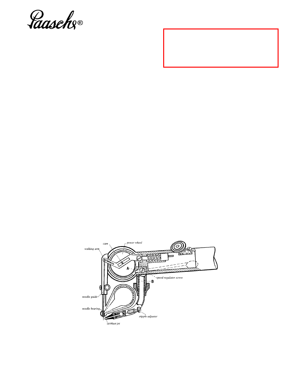
HOW THE AB WORKS:
The illustration below gives you an idea what is going
on inside your AB. As the finger lever is pressed down, air
from your compressor is channeled from the air valve
through the body of the airbrush. The airstream then
splits, and part of the air is pushed across the edge of the
power wheel ( A ) while the rest goes through the airblast
tube ( B ). The edge of the power wheel is serrated, so
that the air pushing against it causes the power wheel to
spin. You will notice that the shaft on which the power
wheel rotates passes through a slot in the walking arm.
Actually, the portion of the shaft which rides in the slot is
offset from center, so that with a cam like action the
spinning of the power wheel causes the walking arm (and
thus the needle) to oscillate back and forth. The speed
regulator screw controls the speed of the power wheel
(and thus the walking arm and needle) by regulating the
volume of air pushing against the power wheel.
When you press down on the finger lever, you let air
into the airbrush and start the needle moving back and
forth. Then as you pull back on the finger lever, the
walking arm is pushed forward, and in turn the oscillating
needle is pushed into the stream of air coming from the
airblast tube. Thousands of times per minute, the needle
retracts into the needle bearing, picks up a coating of color
and then moves forward, drawing the color out of the
bearing and into the airstream, where the color is blown off
the needle and onto the surface you are painting. The
needle is tapered, so that as you pull back farther on the
finger lever, a thicker portion of the needle is exposed to
the airstream and a wider band of color is formed.
A line is thus formed by the action of the needle passing
back and forth in front of the stream of air coming from the
airblast jet, and you control the thickness of that line with
the finger lever. But the quality of that line and the ease
with which you can control it are affected by three other
controls, all of which regulate the volume or the pressure
of the air passing through the airbrush.
METHODS OF CONTROL:
As mentioned before, the speed regulator screw
controls the volume of air hitting the power wheel, and so
controls the speed of the needle. The faster the needle
moves, the more color is being blown onto the surface you
are painting during a given length of time. If you want to
form a thin line, you can do so by having the needle
moving at a high speed and sweeping the airbrush very
quickly over your work, or by having the needle oscillating
much slower and moving the airbrush more slowly.
Obviously the second method offers the most control and
is a major advantage of using the Paasche AB.
There is another method of controlling the speed of the
needle, however, and that is by adjusting the pressure of
the air coming into the airbrush. In this case, if you have
the speed regulator screw turned wide open (counter-
clockwise) with low air pressure (8-15 P.S.I.) from your air
source, the power wheel and needle will move slowly. But
the needle will also move slowly using a high air pressure
(25-35 P.S.I.) with the speed screw turned almost closed
(clockwise).
A comparable situation exists for the flow of air through
the airblast tube. The stipple adjuster screw restricts the
airflow through the airblast jet and across the needle.
When the air is almost closed off, a grainy or stippling
effect is created. But the same effect happens with the
stipple adjuster wide open using a very low air pressure.
As you can see, there are many different combinations
of settings for these three controls (the speed regulator,
the stipple adjuster, and the air pressure) each
combination producing a characteristic effect, both in spray
pattern and handling of the airbrush.
Printed in the U.S.A.
Paasche Airbrush Company
4311 North Normandy Avenue
Chicago, IL 60634-1395
Phone: 773-867-9191 • Fax: 773-867-9198
Website: paascheairbrush.com
E-Mail: info@paascheairbrush.com
All AB needles should have a bow in them in
order to be held securely by the needle
guide and enter the needle bearing properly.
Page 2
Paasche AB (Fine Art) Airbrush Instructions and Parts List
BASIC PRECAUTIONS:
Before starting any adjustments or parts replacements,
a couple of precautions should be observed. The fine tip of
the needle is very delicate, and once damaged it is difficult
to straighten again. Remove the needle before beginning a
repair, or if necessary use an old needle. Secondly, most
of the threaded parts are made of brass, and the threads
are easily stripped. Do not force the parts to do what they
don’t want to do.
(See section “Speed Regulator Screw” for specific
example of this problem.)
ADJUSTING STIPPLE ADJUSTER & AIRBLAST JET:
The stipple adjuster is the screw at the elbow of the
airblast tube. It controls the airflow through the airblast
tube. By turning this screw in (clockwise), you restrict the
volume of air blown out the airblast jet and across the
needle. When the air is almost shut off you create a grainy,
stippling effect.
The threads of the stipple screw can become so loose
that it will not hold its position in the airblast tube and will
gradually turn out as you use the airbrush. As a preventive
measure, we suggest you avoid excessive turning in and
out of this screw. From the fully closed position, you only
need to turn the screw two full turns to fully open this little
valve.
If the screw is too loose, you can tighten the threads’ fit
by pressing a dab of beeswax onto the threads and rolling
the screw between your thumb and forefinger to work the
beeswax into the threads. Only a thin coating is needed.
Then pass the screw very briefly over a match flame,
melting the beeswax into the threads. The wax will adhere
better as you insert the screw back into the airblast tube.
SPEED REGULATOR SCREW:
This screw works much the same as the stipple
adjuster. It controls airflow and thus the speed of the
power wheel and the needle. Again, all the adjustments
happen within a range of two turns of the screw. As noted
before, do not try to force the screw tighter than it wants to
go. You can shear the head of the screw right off, leaving
the screw firmly embedded in the body of the airbrush,
impossible to remove.
POWER WHEEL TOP SHAFT BEARING ADJUSTING:
Adjusting shaft bearings is a procedure that should be
done only if the power wheel is sluggish, is intermittently
binding, or is completely stuck. To check this, remove the
needle, then try to operate the power wheel and walking
arm, pressing down the finger lever and moving it back
and forth. If the power wheel runs smoothly now, the
problem is with your needle, not with the bearing
adjustments. If the problem continues, however, you will
need to adjust the bearings. If the power wheel is sluggish
or will not move at all, it could be that you simply need to
loosen the top bearing a little. Remove the top grease cap,
exposing the top shaft bearing. You will find the bearing
covered with grease, which you may want to remove in
order to see the slot in the top of the bearing better. To
adjust the bearing, use a screwdriver with a blade as wide
as the opening into which the bearing fits. A larger
screwdriver can be filed down to fit exactly the slot in the
bearing. While pressing down on the finger lever for air,
slowly loosen the top bearing (turn counter-clockwise). If
the power wheel frees itself and begins to run smoothly,
you have found the problem. To adjust the bearing
accurately, tighten it again until the power wheel stops,
then loosen it just until the power wheel runs smoothly.
This is a matter of 1/16 to 1/8 turn, never more than 1/4
turn. Do not loosen the bearing beyond the point where the
power wheel frees itself and runs smoothly. Beyond this
point the power wheel will begin to vibrate in the bearing. It
will appear to be running smoothly but then will suddenly
bog down. If this happens, tighten the bearing a little. You
will find the power wheel returns to normal speed.
If you find that the power wheel runs smoothly for a
while then freezes up again, the problem is that the
threads in the power wheel cover have become too worn
to hold the bearing snugly in place. The power wheel
happens to spin in the same direction needed to tighten
the top shaft bearing. If the bearing does not fit snugly in
the power wheel cover, the power wheel will actually drag
the bearing until it stops the power wheel! The remedy for
this situation is the same as for the loose stipple adjuster
or speed control—work beeswax into the threads of the
bearing. Over a long time period, the beeswax will wear
out and this repair will have to be done again.
FINGER LEVER ADJUSTING SCREW:
This screw is located at the back of the finger lever, in
the lever fork, and adjusts the “rest position” of the finger
lever. When you turn the adjusting screw in, the walking
arm is pushed farther into the stream of air from the
airblast jet. By adjusting this screw you set the width of the
line created when the finger lever is simply depressed, but
not pulled back (the “rest position” spray width.) Note: In
the “farthest forward rest position” you get no spray if the
color cup is properly positioned.
Be careful with the two extremes of this adjustment. If
you turn the adjusting screw too far out (counter-
clockwise), the needle moves to the very end of the slot in
the walking arm, and the needle binds between this slot
and the slot in the color cup support. Always check that the
needle is at least a “hair’s breadth” from the very end of
the walking arm slot.
On some ABs, if you turn the adjusting screw too far in
(clockwise), the walking arm will be pushed too far forward
and will hit the front of the opening in the power wheel
cover through which it extends.
SHAPING THE NEEDLE:
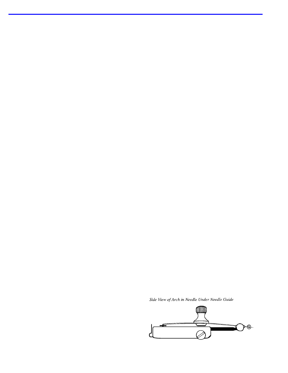
In general an AB needle should be curved in two
directions. Viewed from the side the needle should have a
slight arch, so that the needle guide can hold it firmly in the
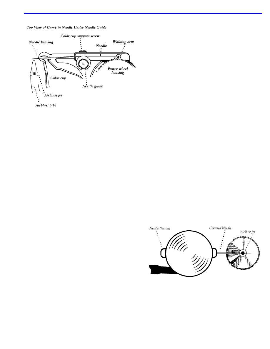
slot in the needle bearing. Viewed from the top, the needle
should curve underneath the lip of the needle guide screw.
Both arch and curve should be gradual bends along the
length of the needle, with no sudden bends or angles.
About 3/8 inch at the tip of the needle—that portion which
rides in and out of the needle bearing—should be left
straight. In fact, try not to touch the tip at all as you are
arching and curving the needle, for fear of distorting the
needle. Remember that you are shaping the needle to fit
your particular airbrush.
The arch (side view) of the needle does not need to be
too great—just enough to give a little tension when the
needle guide is screwed all the way down. With a more
extreme arch the tip of the needle rides in the bearing at
too great an angle. In addition, the motion of the needle is
not as smooth, because the crest of the arch is passing in
and out from under the needle guide.
Continued on page 3
Paasche AB (Fine Art) Airbrush Instructions and Parts List
Page 3
SHAPING THE NEEDLE (Continued from page 2):
The other curve of the needle (top view) is the one that
varies most from airbrush to airbrush. Again, there should
be a gradual curve, with a straight section at the tip of the
needle. The idea is to curve the needle completely under
the lip of the needle guide (if the needle rides at the edge
of the lip, the needle will not stay in place as it oscillates),
and at the same time for the tip of the needle to ride
nearly parallel with the edges of the slot in the needle
bearing. It is normal for the tip of the needle to sit at a
slight angle in the needle bearing—with the curve in the
needle, you can’t help it. But this angle should be
minimized, to keep the needle from binding in the needle
bearing.
ADJUSTING THE COLOR CUP:
The color cup is clamped into the color cup support by
tightening the screw on the front side of the support. To
determine how far the color cup should project from the
support, first run the Finger Lever Adjusting Screw out
(counter-clockwise) until there is just a “hair’s breadth”
remaining between the butt end of the needle and the end
of the slot in the walking arm. This finger lever position is
called the “farthest forward rest position.”
Now slide the color cup in or out of the support until the
tip of the needle comes to the end of the slot in the
needle bearing but does not project from it. Attach the AB
to your air compressor and start the needle moving with
the finger lever in the “farthest forward rest position”
(push down the lever but do not pull back). Slide the color
cup out until the needle does not project from the
bearing—you now have the correct color cup position for
the “farthest forward rest position.” Note: The rapidly
moving tip is easier to see against a white background.
The color cup can also be partially rotated to allow you
to spray onto a surface more or less horizontally. You will
notice as you rotate the color cup, the position of the
needle bearing changes, necessitating a readjustment of
the airblast tube and in a few instances even a
recurvature of the needle. For this reason you will
probably want to find one position for the color cup which
is comfortable for you and then stick with it. The amount
of tilt is limited, from a position in line with the power
wheel housing to about 30 degrees below this line.
AIR VALVE PARTS REPLACEMENT:
This is rarely necessary, but these parts can be
replaced fairly simply. Unscrew the valve nut and remove
the spring plunger, and washer in that order. Use a small
stiff wire with a slight hook bent into the end of it to fish
out the washer. Then place a new washer on the plunger
and insert the plunger and washer together. To avoid
compressing the springs too far, screw the valve nut in
only until it is slightly below the level of the air valve
casing.
ADJUSTING THE AIRBLAST TUBE:
Check that the color cup is properly positioned as
described above. With pliers loosen the locknut where the
airblast tube attaches to the body of the airbrush. Now
rotate the airblast tube, screwing it in (counter-clockwise)
or out (clockwise) until the airblast jet is about 1/64 inch
from the end of the needle bearing. Now with the air
turned off pull back the finger lever so that the needle is
pushed out in front of the airblast jet. The distance from
the needle to the tip of the jet should be about 1/64 inch.
Very carefully you may bend, if necessary, the airblast
tube where it enters the locknut and arches to the body of
the airbrush to accomplish this second adjustment. Do
not bend at the elbow of the airbrush tube or in front of
the elbow for two reasons: (1) curved tubing such as the
elbow in the airblast tube is inherently more brittle and
tends to crack if leverage is applied to it, and (2) there is a
soldered joint where the stipple adjuster is attached to the
elbow, which may break if pressure is applied.
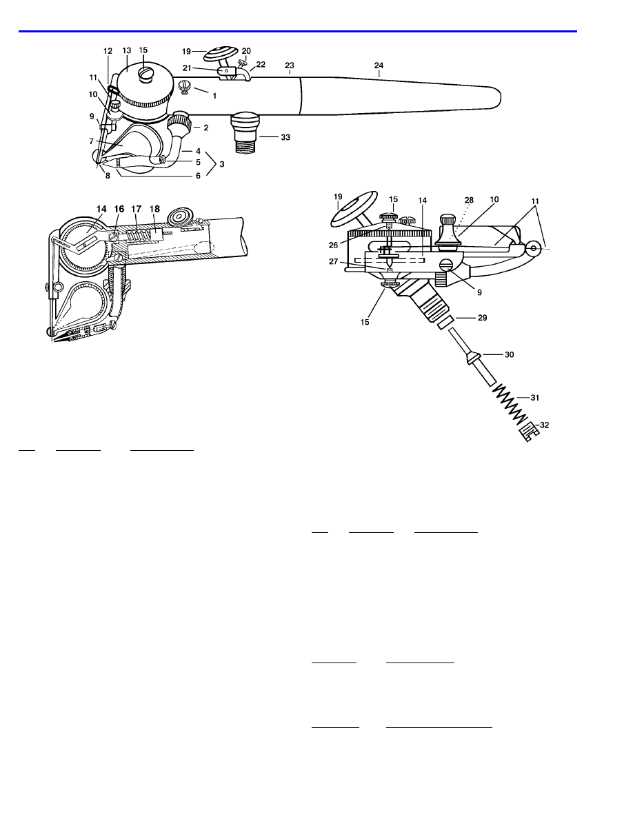
Finally set the airblast tube so that the needle, when
extended, passes through the center of the airstream
from the airblast jet—that is, as you sight down the hole in
the airblast jet, the needle should cross the center of that
hole. If the needle is off center, you will get a stippling
effect, and for some applications you may wish to set the
airblast tube in this way purposely.
The “AB” Airbrush is not suitable for use with alcohol or
lacquer colors. Any water color, opaque or oil can be used with
brilliant results.
See Page 4 for AB Replacement Parts and Parts Numbers.
Page 4
Paasche AB (Fine Art) Airbrush Instructions and Parts List
If Parts are worn and aforementioned repairs are not
proving helpful, Paasche suggests the purchase of
replacement parts listed below. Any Parts not listed MUST
be replaced at the Factory.
* Denotes Part to be Fitted at the Factory.
For further information contact Paasche Service
Department.
NO.
PART NO.
DESCRIPTION
1.
A-140
Speed Regulator Screw
2.
A-139
Air Blast Tube Locknut
3.
A-173
Right Hand Air Blast Tube Assembly
A-173LH
Left Hand Air Blast Tube Assembly
4.
*A-138
Right Hand Air Blast Tube
*A-138LH
Left Hand Air Blast Tube
5.
A-146
Stipple Adjuster
6.
A-101
Air Blast Jet
7.
A-179
Right Hand Color Cup Assembly
A-179LH
Left Hand Color Cup Assembly
8.
A-177
Right Hand Needle Bearing
A-177LH
Left Hand Needle Bearing
9.
A-160
Color Cup Screw
10.
A-142
Needle Guide
11.
A-116
Needles (Dozen)
A-116LH
Left Hand Needles (Dozen)
12.
A-107
Walking Arm
13.
*A-131
Right Hand Wheel Housing
*A-131LH
Left Hand Wheel Housing
14.
*A-172
Power Wheel & Shaft Assembly
15.
A-114
Grease Cup
16.
A-106
Walking Arm Shaft (Screw)
17.
A-105
Walking Arm Spring
18.
A-104
Walking Arm Plunger
19.
A-121
Finger Lever and Button
20.
A-146
Lever Adjusting Screw (Old# A-60)
21.
A-58
Lever Pivot
22.
A-14
Lever Fork
23.
A-122
Right Hand Shell (Includes A-128)
A-122LH
Left Hand Shell (Includes A-128)
SPECIAL NOTE: Periodically the
Grease Cup (Item 15) should be
removed and the Bearing checked
for Grease - Apply if necessary.
NO.
PART NO.
DESCRIPTION
24.
F-143
Handle (Old Style A-161)
VL-118
Protecting Cap (Not Supplied on F-143)
26.
A-133
Top Shaft Bearing
27.
A-154
Bottom Shaft Bearing
28.
A-143
Needle Guide Spring
29.
A-52
Valve Washer (Dozen)
30.
H-21A
Valve Plunger
31.
A-22
Valve Spring
32.
A-23A
Air Valve Nut
33.
A-128
Valve Casing
PART NO.
ACCESSORIES
A-34
Airbrush Hanger
A-64
Screw Driver
A-117
Tweezers
AB-CASE
Case
PART NO.
HOSE & ACCESSORIES
A-1/8-6
Air Hose W/ Couplings
A-1/8-6MT
Air Hose W/ MT Moisture Trap
AC-1/8
-1/4” Coupling
AC-20
1/8”-1/4”-40 Coupling
MT
Moisture Trap
HF-1/4
Valve Assembly
Wyszukiwarka
Podobne podstrony:
TG TALON Paasche Lista Części
VL i VLS Aerografy Paasche Lista Części
VSR90 Paasche Lista Części
Millennium Paasche Lista Części
Aerograf F#1 Paasche Lista Części
Aerograf SA Paasche Lista Części
Lista czesci
lista części KUCHNIA
Lista czesci Arkusz
lista czesci
Lista czesci, IMIR, II stopień, Semestr 1, Logistyka
lista czesci oryginalnych
786931 Lista czesci V
Karty Gotowe Lista czesci id 72 Nieznany
783210 Lista czesci V
Lista czesci
Lista części(1)
więcej podobnych podstron