INSTRUCTIONS AND PARTS LIST MIL-8/21/2008
Supersedes Instructions & Parts List MIL-1/2008
WARNING: Spray materials may be harmful if inhaled or
allowed to come into contact with the skin or eyes. Consult
the product label and Material Safety Data Sheet supplied
for the spray material. Follow all safety precautions.
CAUTION: Well Ventilated Area Required to remove
fumes, dust or overspray. Secure airhose to Airbrush
with V-62 Wrench for safety and to prevent air leaks.
M a x i m u m A i r P r e s s u r e 7 5 P . S . I .
M
M
M
M II
I
I L
L
L
L L
L
L
L E
E
E
E N
N
N
N N
N
N
N II
I
I U
U
U
U M
M
M
M
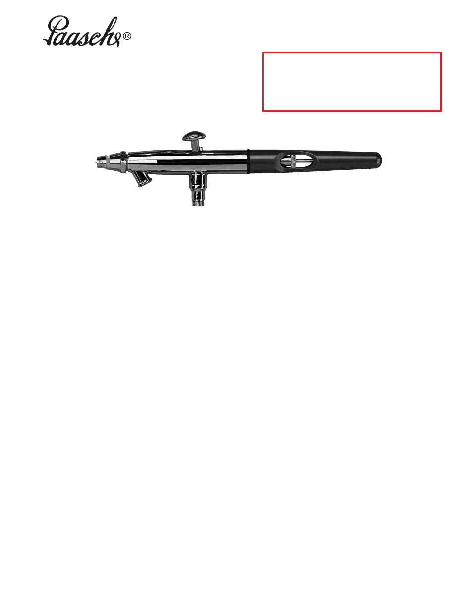
DOUBLE ACTION–INTERNAL MIX
AIRBRUSH for the 21ST CENTURY
INTRODUCTION:
The
M
M II L
L L
L E
E N
N N
N II U
U M
M
features a polished chrome plated
brass body with a red anodized aluminum Cut-Away
Handle – thinner barreled body for easy grip – round trigger
button that rolls under your finger for greater comfort and
better control and the same great airbrushing results
achievable with your Paasche “VL”.
OPERATING INSTRUCTIONS:
The
M
M II L
L L
L E
E N
N N
N II U
U M
M
is held in the same manner as a pen,
with the index finger resting comfortably over the finger
button.
1.
Attach airhose to air supply and hold loose end away
from eyes then allow air to blow a few seconds. Shut
off air supply before attaching airhose to airbrush
wrench tight. This procedure will remove dirt from air
supply line and hose.
2.
Attach airhose coupling to airbrush with V-62
Wrench.
3.
For
M
M II L
L L
L E
E N
N N
N II U
U M
M
attach the color cup or bottle
assembly to color socket using a firm twisting motion.
4.
Remove Head Protecting Cap Before Spraying-#1.
5.
Press down on Finger Lever Assembly-#8 to release
air and pull back on button to control quantity of color.
6.
To spray a fine line without heavy ends, start moving
the airbrush without release of color then start the color
at the beginning of the line and stop the color at the
end, but continue the motion of the airbrush after the
color has stopped.
7. Practice this movement until you can spray a fine line
or a broad pattern without heavy build up at the
beginning or end of your strokes.
8. Speed of movement controls density of color and
fading effects at beginning and end of strokes.
9. For detail, hold the airbrush close to the surface then
push down for air and pull back very slowly on the
Finger Lever Assembly-#8 for color.
10. For background work and broad effects, hold the
airbrush away from work and pull back on Finger Lever
Assembly-#8 to release required amount of color.
11. For more instruction see the “22 Airbrush Lessons for
Beginners” booklet enclosed with your airbrush.
CLEANING PROCEDURE:
1. Pour remaining color back into its container.
2. Rinse and wipe color cup or bottle assembly clean.
3. Spray a small amount of water/solvent through the
airbrush until it comes out clear.
4. To back-flush color from the airbrush into the color
bottle keep bottle assembly attached. Place one finger
over the Aircap-#2 of the airbrush and release some
air by depressing the Finger Lever Assembly-#8. This
causes back pressure which induces a bubble action
inside the airbrush and container. This helps clean the
fluid passages.
5. See Page 2 for a complete list of all
M
M II L
L L
L E
E N
N N
N II U
U M
M
components. See Pages 2 & 3 for more instructions on
cleaning and adjusting the
M
M II L
L L
L E
E N
N N
N II U
U M
M
.
Printed in the U.S.A.
Paasche Airbrush Company
4311 North Normandy Avenue
Chicago, IL 60634-1395
Phone: 773-867-9191 • Fax: 773-867-9198
Website: paascheairbrush.com
E-Mail: info@paascheairbrush.com
Paasche
M
M II L
L L
L E
E N
N N
N II U
U M
M
Double Action Airbrush – Internal Mix
Page 2
M
MIIL
LL
LE
EN
NN
NIIU
UM
M
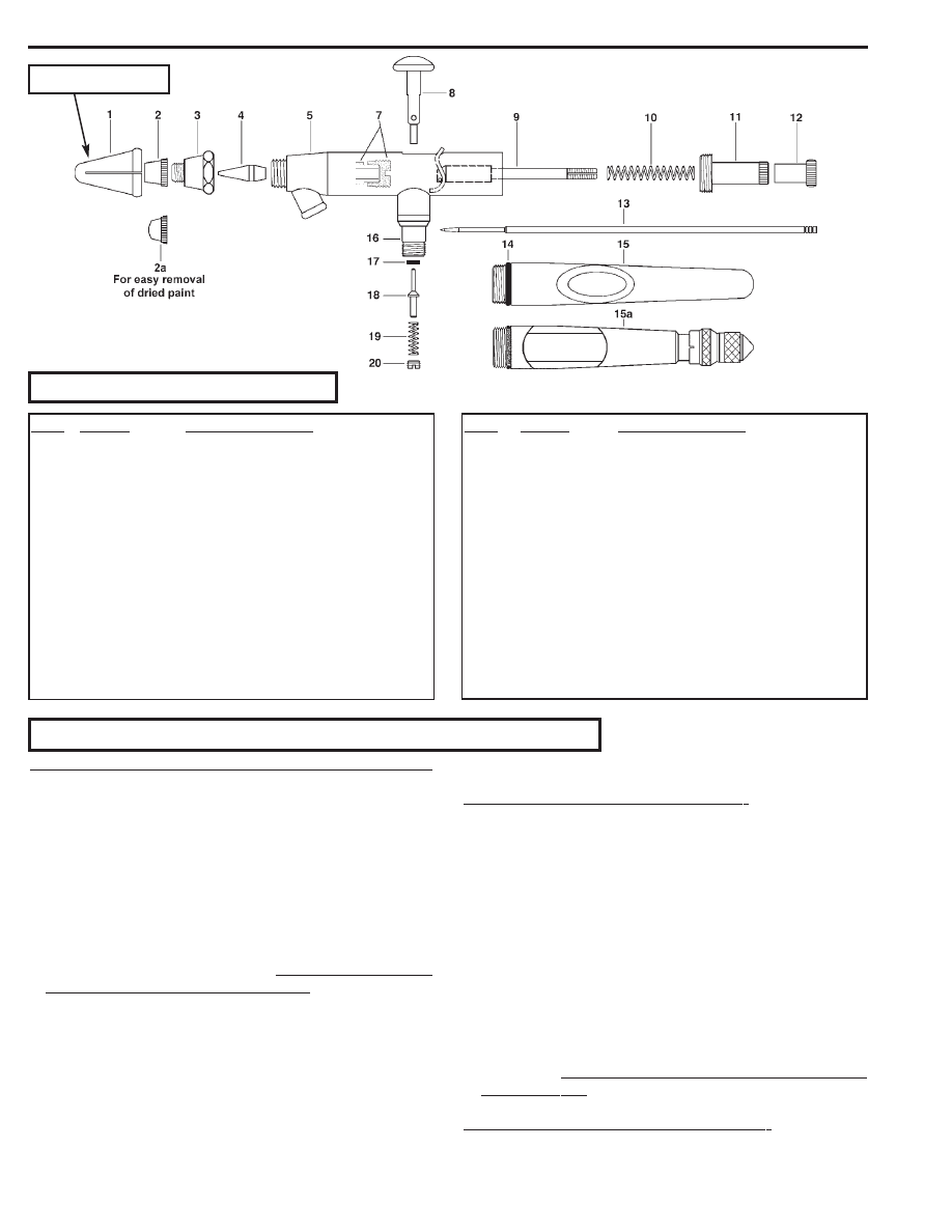
Components
NO. PART
DESCRIPTION
1.
MIL-8
Head Protecting Cap
2.
VLA-3
Aircap
2a.
PP-1, 3 or 5
Paint Picker Aircap (Optional) for easy
removal of dried paint - match to Tip.
3.
VLB
Aircap Body
4.
VLT-3
Tip
5.
MIL-2
Shell Assembly
7.
MU-612
Teflon® Packing & Packing Nut
(sold as set) ® DuPont
8.
MIL-3
Finger Lever Assembly
9.
MIL-4
Rocker Assembly
10.
V-140
Spring
NO.
PART
DESCRIPTION
11.
V-136A
Needle Adjusting Sleeve
12.
VL-141
Locknut
13.
VLN-3
Needle
14.
MIL-12
“O” Ring
15.
MIL-10
Cut-Away Aluminum Handle
15a.
TAL-34
Handle & Stop Assembly - allows for
preset paint flow (Optional)
16.
MIL-9
Valve Casing
17.
A-52
Valve Washer (Dozen)
18.
H-21A
Valve Plunger
19.
A-22
Valve Spring
20.
A-23A
Air Valve Nut
A. REMOVING/REPLAClNG THE NEEDLE AND HANDLE:
1. Unscrew the handle and loosen the Locknut-#12 by turning
counterclockwise. Depress the Finger Lever Assembly-#8
and hold in Down position while removing or inserting the
needle. This assures the needle moves freely through the
finger lever. Gently remove the needle, rotating if
necessary, DO NOT force out!
2. A loose needle can cause sputtering if there is any air
leakage around the needle and Packing-#6. If there is no
noticeable drag on the needle by the packing then tighten
Nut-#7.
3. Inspect the condition of the needle. If it is bent or misshapen
in any way, replace it with a new needle. A bent needle can
damage or split the Tip-#4 causing bubbles or a rough
spray pattern.
4. Hold Lever Assembly-#8 in DOWN position, insert the
new needle into the Rocker Assembly-#9. Gently push
needle through, rotating if necessary, until the needle’s
point is visible through the Tip-#4 of the airbrush.
5. Release Finger Lever Assembly-#8 and tighten Locknut-
#12 by turning clockwise.
6. Replace the handle. Slowly screw the handle into the
airbrush shell (1) counter-clockwise until you feel or hear
a slight “click.’’ Then rotate the handle (2) clockwise a
slight turn to meet the threads. Continue to screw handle
into the airbrush shell until the threads are no longer visible.
B. REMOVING THE ROCKER ASSEMBLY:
1. Unscrew handle from the end of airbrush shell.
2. Remove Locknut-#12 and needle (see above-removing
and replacing the needle and handle.)
3. Depress Finger Lever Assembly-#8 and Pull BACK. Keep
in DOWN and BACK position, this secures Rocker
Assembly-#9, while removing balance of parts.
4. Unscrew and remove Needle Adjusting Sleeve-#11 and
Spring-#10.
5. Keep Finger Lever Assembly-#8 in DOWN position, allow
finger lever to go FORWARD to release the Rocker Assembly-
#9 for removal.
6. The Rocker Assembly-#9 should now be loose. Tilt the
threaded end of the Rocker Assembly-#9 UPWARDS and
gently remove from the back of the airbrush shell (see
Illustration. DO NOT FORCE REMOVAL OF ROCKER
ASSEMBLY-#9!
C. REPLACING THE ROCKER ASSEMBLY:
1. Depress Finger Lever Assembly-#8 and hold in DOWN
position.
2. Insert Rocker Assembly-#9 into airbrush shell with
M
MIIL
LL
LE
EN
NN
NIIU
UM
M
Adjusting & Cleaning Procedures
Remove MIL-8 Head Protecting
Cap before spraying (Item #1)

Rocker-portion in FORWARD Position.
3. When the top of the Rocker is visible through the opening
in the top of the airbrush shell (by finger lever), pull BACK
on Finger Lever Assembly-#8 until it touches the Rocker.
Hold it there firmly, this secures the Rocker Assembly-#9
in place while re-assembling parts!
4. The Needle Support (part of the Rocker Assembly-#9) is visible
through the end of the airbrush shell and will be loose.
5. Keep Finger Lever Assembly #8 with Rocker secured, in
DOWN and BACK position, while replacing the Spring-
#10 and Needle Adjusting Sleeve-#11.
6. Screw-in Needle Adjusting Sleeve-#11 until desired
tension on the Finger Lever Assembly-#8 is achieved.
7. Replace the needle, with the Finger Lever Assembly-#8 in
the DOWN position, then replace the Locknut-#12.
8. Release Finger Lever Assembly-#8. You should feel
tension on the lever and it should spring-up if you depress
and release it. If not, remove parts as above and repeat
process.
D. REPLACING THE FINGER LEVER ASSEMBLY:
If the Finger Lever Assembly-#8 is removed or dislodged, it
must be replaced inside the airbrush shell, before the
Rocker Assembly-#9 and needle are re-inserted.
1. Hold Finger Lever Assembly-#8 so the opening in the lever is
in-line with the opening in the end of the airbrush shell.
2. The Piston, which pivots on the end of the Finger Lever-
#8, must be kept in DOWN position.
3. Insert Finger Lever Assembly-#8 with Piston straight
DOWN through the opening in the top of the airbrush shell.
View your progress through the end of the airbrush shell.
Make sure the Piston goes STRAIGHT DOWN into the
base opening of the Valve Casing-#16 (inside shell).
Sometimes this takes several tries. Take your time.
4. Once the Piston of the Finger Lever Assembly-#8, has
been inserted into the Valve Casing-#16, you will be able
to press down on the Finger Lever Assembly-#8 and it will
not fall out. Proceed to replace Rocker Assembly-#9 and
balance of parts as above.
E. REPLACING THE TIP:
1. Remove handle, loosen Locknut-#12 and withdraw
needle about one inch.
2. Un-screw the Aircap Body-#3 and remove. The Tip-#4 is
now exposed and should be easily removed by hand.
3. Place a new Tip-#4 into position and tighten Aircap Body-
#3 to airbrush shell using V-62 Wrench. Re-insert needle
to forward position and tighten Locknut-#12.
F. ADJUSTING OR REPLACING WORN PACKING WASHER:
1. If Teflon
®
Packing-#7 becomes worn or loose it must be
tightened or replaced.
2. You will need a small screwdriver to remove or tighten the
Packing Nut.
3. When replacing your Teflon
®
Packing press Packing onto
the Packing Nut-#7. Use a small screwdriver to tighten
packing nut into shell until it is tight then back out one-half
turn, may vary.
4. Now insert needle - you should feel a slight resistance. If
too loose or too tight adjust the Packing Nut with
screwdriver until you feel some slight resistance.
5. Now completely re-assemble guts of Airbrush.
G. USING A REAMER:
1. The Reamer- is Optional Equipment for use in removing
hardened color from inside tapered surface of the Tip-#4.
It should be used only if color has become too hard for
water or solvent to dissolve.
2. If it does become necessary to ream the Tip-#4, remove
tip first. Insert Reamer- into the large opening of tip and
with slight pressure turn reamer slowly to remove
hardened particles.
3. Remove reamer and flush water or solvent through the tip
to thoroughly clean away any loose particles.
H. CLEANING THE AIRBRUSH:
1. If Aircap-#2 is clogged with color, remove it from the Aircap
Body-#3 and clean Aircap using a toothpick covered with
cotton and saturated in water or solvent. Never use a sharp
instrument or Reamer- to clean the Aircap.
2. It is not recommended to soak the entire airbrush shell in
water or solvent. The Valve Washer-#17 can absorb the
liquid, causing it to swell or dry out, resulting in air leakage
inside the airbrush. Disassemble all parts before
immersing in water or solvent.
I. TROUBLE SHOOTING:
1. If paint bubbles appear in the color cup, try tightening the
Aircap Body-#3 and the Aircap-#2 with the V-62 Wrench-
provided.
2. If paint is not spraying from the Aircap-#2 check the color
cup and color inlet of the airbrush shell. Make sure they
are free from any dried color, dirt or foreign matter.
3. An uneven or sputtering emission of color from the Aircap-
#2 indicates that either the material being sprayed is to
thick or the air pressure is to low.
4. An air leak, after the Finger Lever Assembly-#8 has been
released, indicates that foreign matter has worked into the
Air Valve-#16 or Valve Washer-#17 and damaged them.
J. TO RESOLVE THIS PROBLEM:
1. Remove Airhose from Airbrush and blow out any accumu-
lation in the Valve Casing-#16.
2. Using a small screwdriver, remove Valve Nut-#20, Valve
Spring-#19 and Valve Plunger-#18.
3. The old Valve Washer-#17 can be removed by inserting
the blunt end of an airbrush needle through the top of the
Valve Casing-#16 and pushing DOWN. To expose the top
of the Valve Casing-#16, the Finger Lever Assembly-#8,
Rocker Assembly-#9 and Needle-#13 must be removed.
NOTE: Cover sharp point of needle to avoid Injury.
4. Blow out dirt from the Valve Casing-#16 and check valve
seat for dirt and nicks. Valve seat is located inside the
Valve Casing where the Valve Washer-#17 rests. If
damaged, replace Valve Casing-#16.
5. Install a new Valve Washer-#17 onto the long thin side of
the Valve Plunger-#18.
6. Re-assemble Valve Plunger-#18 followed By Valve
Spring-#19 and Valve Nut-#20.
7. The Valve Nut-#20 must be screwed to a depth below the
surface of the Valve Casing-#16.
8. It is not necessary for the Air Valve Casing-#16 to be
removed except to replace if damaged.
Paasche
M
M II L
L L
L E
E N
N N
N II U
U M
M
Double Action Airbrush – Internal Mix
Page 3
Paasche
M
M II L
L L
L E
E N
N N
N II U
U M
M
Double Action Airbrush – Internal Mix
Page 4
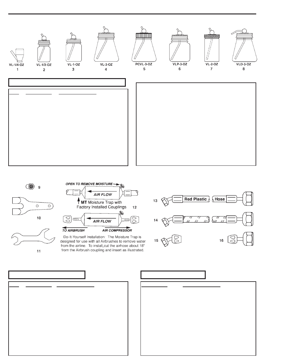
NO.
PART NO.
DESCRIPTION
1.
VL-1/4-OZ
Metal Color Cup (7cc)
2.
VL-1/2-OZ
Color Bottle Assembly (14.5cc)
VL1/2
1/2 oz. Cover Assembly
VF-17
Color Tube
3.
VL-1-OZ
Color Bottle Assembly (29cc)
VL1
1 oz. Cover Assembly
VF-17
Color Tube
5-G
Gasket
4.
VL-3-OZ
Color Bottle Assembly (88cc)
VL3
3 oz. Cover Assembly
VF-14
Color Tube
3-JG
Gasket
5.
PCVL-3-OZ
Nylon Cover/Metal Tube Bottle
Assembly (88cc)
PCVL3
Nylon Cover Assembly
VF-14M
Metal Color Tube
3-JG
Gasket
6.
VLP-3-OZ
Plastic Bottle Assembly (88cc)
VL3
3 oz. Cover Assembly
VF-14
Color Tube
3-JG
Gasket
7.
VL-2-OZ
Aluminum Cup Assembly (60cc)
VF-2-5/8
Color Tube
3-JG
Gasket
8.
VLD-3-OZ
Decorator Bottle Assembly (88cc)
VLD3
3 oz. Cover Assembly
VF-14
Color Tube
3-JG
Gasket
M
MIIL
LL
LE
EN
NN
NIIU
UM
M
ACCESSORIES
M
MIIL
LL
LE
EN
NN
NIIU
UM
M
CUP AND BOTTLE ASSEMBLIES
NO.
PART NO. DESCRIPTION
9.
VL-127
Strainer for Teflon®White
Color Tubes Only
10.
A-34
Hanger
11.
V-62
Wrench
12.
MT
Moisture Trap (Do-It-Yourself
Installation)
13.
HP-1/8
PVC Red Plastic Airhose w/cplgs.
14.
A-1/8
Braided Airhose w/Couplings
15.
AC-20
1/8"-1/4"-40 Coupling (To Airbrush)
16.
AC-1/8
-1/4" Coupling (To Compressor)
PART NO.
DESCRIPTION
F-143
Red Plastic Handle
R-75AR
Reg. & Filter w/Gauge
VL-54
Reamer
D500
Air Compressor (115v.,60cyl.)
HSSB-22-16
Hobby-Shop Spray Booth
PP
Paint Picker Aircap
A-194
Deluxe Airbrush Hanger
Accessories not shown
Wyszukiwarka
Podobne podstrony:
TG TALON Paasche Lista Części
VL i VLS Aerografy Paasche Lista Części
VSR90 Paasche Lista Części
AB Turbina Paasche Lista Części
Aerograf F#1 Paasche Lista Części
Aerograf SA Paasche Lista Części
Lista czesci
lista części KUCHNIA
Lista czesci Arkusz
lista czesci
Lista czesci, IMIR, II stopień, Semestr 1, Logistyka
lista czesci oryginalnych
786931 Lista czesci V
Karty Gotowe Lista czesci id 72 Nieznany
783210 Lista czesci V
Lista czesci
Lista części(1)
więcej podobnych podstron