THE STRUCTURE AND HEAT TREATMENT
OF LOW CARBON STEEL
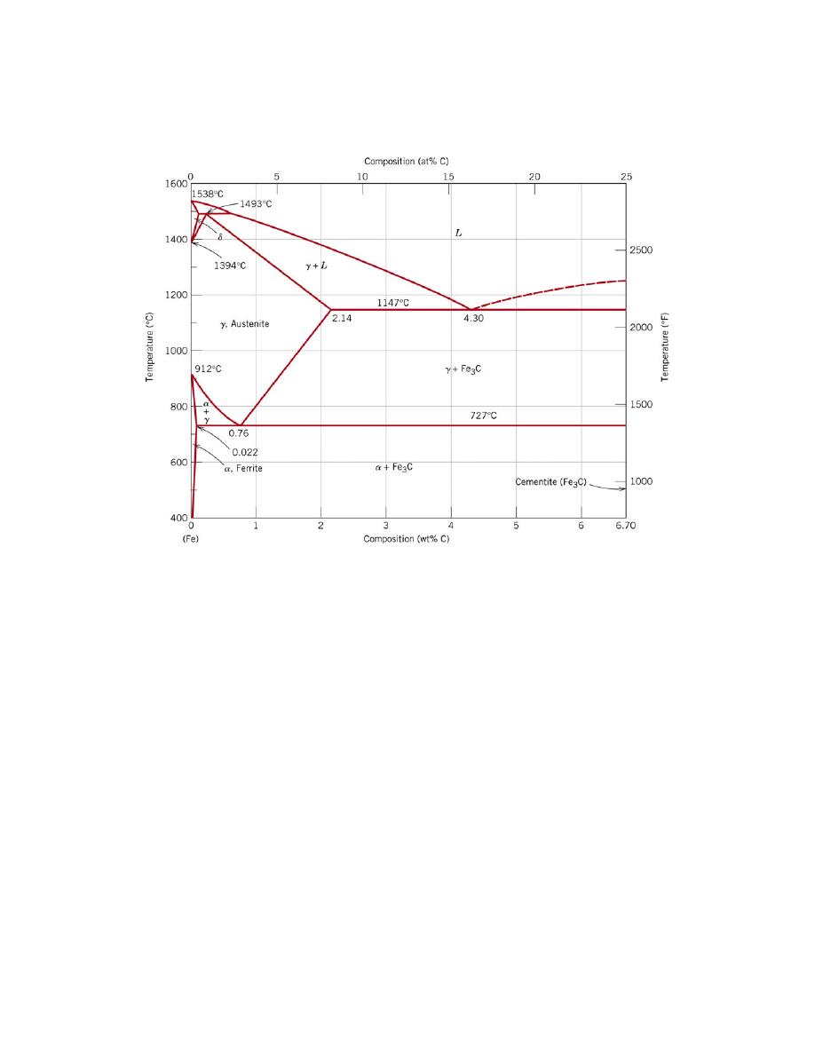
Figure 1. The iron-iron carbide phase diagram [1]
If a sample of this steel is heated in a furnace, at a high enough temperature, it
will enter the austenite region of the phase diagram. In austenite, or
γ, the iron atoms in
the steel are arranged in a face centered cubic (FCC) structure.
When cooled from this region, the steel will enter a region where both ferrite and
austenite co-exist. Ferrite, or
α, is body centered cubic (BCC) and cannot dissolve as
much of the interstitial carbon as the austenite. Therefore, carbon in the regions that are
transforming to ferrite must diffuse to the still existing austenite regions, "enriching"
these regions. The phase diagram allows the prediction of how much ferrite and austenite
exist, as well as the carbon composition of each, when the phases are in equilibrium at
any temperature and composition (see Ref. 1 for a discussion of the lever rule).
Below
727
°C, the remaining austenite phase (which is of the eutectoid
composition, 0.76 weight percent (wt %) carbon) is unstable and transforms into ferrite
and Fe
3
C. This new arrangement of ferrite and carbide is known as pearlite and the Fe
3
C
phase is termed carbide or cementite. Again, the ferrite cannot dissolve 0.76 wt %
carbon, so the carbon atoms in the ferrite regions must diffuse to the newly forming
regions of carbide. Figure 2 shows a sketch of the carbon atoms diffusing. Pearlite is
usually a lamellar (layered) structure, and is shown in Figure 3.
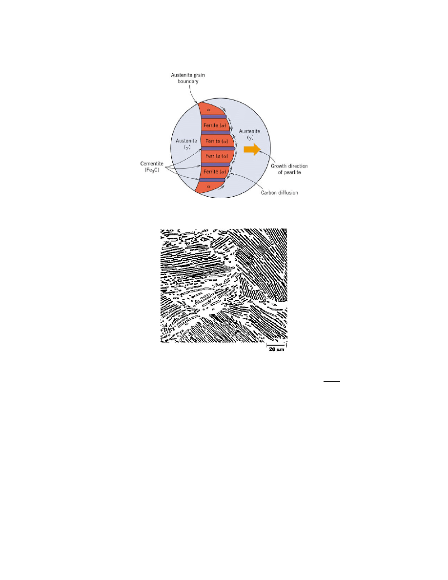
Figure 2. Decomposition of austenite into pearlite. [1]
Figure 3. Photograph of eutectoid steel showing the pearlite microstructure 500X. [1]
Figure 4 shows the formation of these different phases during the slow cooling of
austenite, in a hypothetical steel alloy. In Figure 4A, the steel has just entered the
ferrite+austenite region of the phase diagram, and ferrite grains have started to nucleate at
the austenite grain boundaries. In 4B, the steel is just above the eutectoid temperature.
(Again, the amount (volume or percent weight) of both the austenite and ferrite regions
can be calculated using the lever rule.) In 4C, the sample has cooled to just below the
eutectoid temperature and the remaining austenite is transformed into pearlite and has the
typical lamellar structure, as in Figure 3.
Because the formation of ferrite and pearlite depend on the diffusion of carbon, it
is possible to cool austenite so quickly that the carbon atoms do not have sufficient
mobility to arrange themselves into the thermodynamically preferred state predicted by
the phase diagram. When steel is supercooled by, for example, water quenching, the iron
attempts to transform into its preferred BCC lattice structure (ferrite), but the carbon
remains in solution and distorts the iron matrix into a body centered tetragonal (BCT)
configuration. This BCT steel is known as martensite (M).
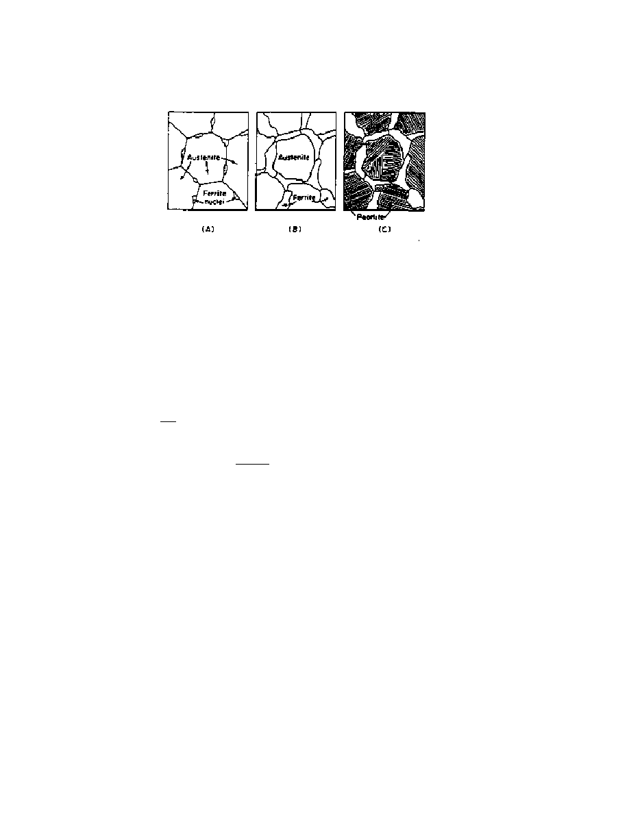
Figure 4. Austenite transforming into ferrite and pearlite under slow cooling [2]
This transformation to martensite requires the Fe + C atoms to move very little
(less than 1A) and is completed almost instantaneously. It does not rely on carbon
diffusion. Martensite is a metastable phase. It is not the thermodynamically preferred
condition, but there isn't enough thermal energy to allow the carbon atoms to diffuse and
allow the more stable ferrite and carbide arrangement to form. Therefore, the iron
transforms to the BCC-like phase (BCT) and reduces the free energy from the FCC
phase, but not as much as if it could form the preferred phase. Note that martensite can
only be formed by the fast cooling of austenite. Quickly cooling ferrite, or other phases
of steel, does not produce martensite.
If the cooling of the austenite is too fast for the carbon atoms to diffuse into a
pearlite lamellae structure, but is still slow enough for the carbon atoms to diffuse short
distances and form carbides, bainite is formed. Instead of forming a layered structure, the
carbide forms as small particles.
All of these transformations are shown in the TTT (Time Temperature
Transformation) curve. See Figures 5 and 6. The shape of this curve is dependent on the
particular type of steel used. Figure 6 shows several arbitrary cooling paths and the
resulting structure.
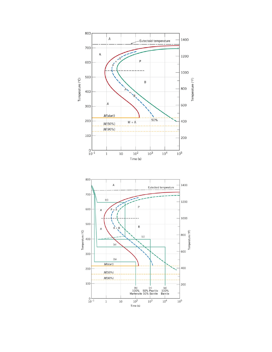
Figure 5. Isothermal transformation diagram for a Fe-C alloy of eutectoid composition:
A, austenite; B, bainite; M, martensite; P, pearlite. [1]
Figure 6. Isothermal transformation diagram for a Fe-C alloy of eutectoid composition
and arbitrary isothermal heat treatments. [1]

Path (a) shows a rapidly cooled sample to 350 °C, hold for 10
4
s, and quench to
room temperature. At 350 °C austenite transforms isothermally to bainite. By 10
4
s,
100% of the specimen is bainite, and no further transformation is possible, even though
the final quenching line passes through the martensite region of the diagram.
Path (b) shows a rapidly quenched sample to 250 °C, hold for 100 s, and quench
to room temperature. After 100 s at 250 °C, the sample is 100% austenite. As the
specimen is cooled through the martensite region, more and more of the austenite
transforms to martensite until the microstruture is finally 100% martensite at room
temperature.
Path (c) 2 shows a rapidly cooled sample to 650 °C, hold for 20 s, rapidly cooled
to 400 °C, hold for 10
3
s, and quench to room temperature. At 650 °C, pearlite begins to
form; by the time 20 s has elapsed, approximately 50% of the specimen has transformed
to pearlite. The rapid cool to 400 °C is indicated by the vertical line; during this cooling,
very little, if any, remaining austenite will transform to either pearlite or bainite, even
though the cooling line passes through pearlite and bainite regions of the diagram. At 400
°C after 10
3
s have elapsed, all the remaining austenite will have completely transformed
to bainite. Upon quenching to room temperature, any further transformations is not
possible inasmuch as no austenite remains; and so the final microstructure at roon
temperature consists of 50% pearlite and 50% bainite
As mentioned earlier, the martensite structure is metastable and will transform
into a more thermodynamically stable structure under certain conditions. For example,
by tempering martensite (heating it), a transformation occurs. The carbon atoms that are
trapped in the iron lattice are now more mobile and diffuse to form carbide (as they do
when pearlite or bainite are formed.) This time however, they do not form the typical
pearlite lamellar structure but a spheroidal morphology. The size, structure, and quantity
of the carbides are dependent on the temperature and on the time the transformation takes
place. A higher temperature or a longer tempering time results in larger carbide spheres.
As would be expected, the physical properties of the steel are very dependent on
the type of microstructure that exists (pearlite, bainite, martensite, tempered martensite,
etc.) Martensite is a very hard microstructure. It has a fine grain size and the interstitial
carbon atoms strain the Fe lattice. Both of these inhibit the dislocation movements that
allow plastic deformation.
Tempered martensite is softer and more ductile. It is still relatively hard, though,
since the carbide spheres are obstacles which inhibit dislocation movement. If the
spheres are allowed to grow too large, the number of obstacles decreases and the material
becomes softer. This condition is known as overtempering.
Pearlite is relatively soft. Dislocations can move freely through the ferrite and
therefore the material can easily plastically deform. The carbide phase is very strong but
very brittle, while the ferrite phase is more ductile.
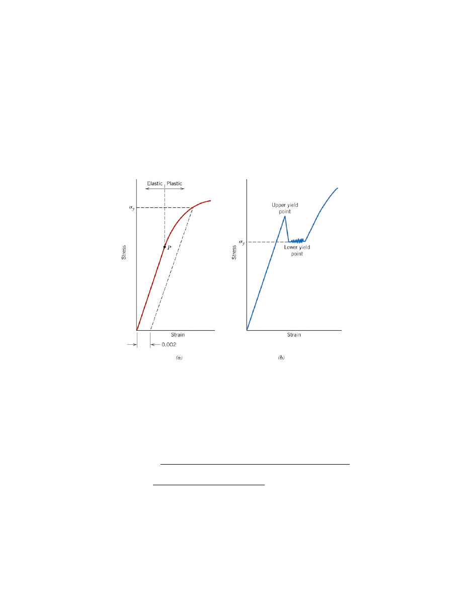
When low carbon steel is tensile tested, a "yield drop," as shown in Figure 7, is
occasionally seen. As the figure shows, the sample elastically deforms normally until it
reaches an (upper) yield point. However, unlike other materials in which the stress
continues to rise as plastic yielding occurs, low-carbon steels often exhibit a drop in
stress with increasing strain. Eventually, the material starts to harden and the stress
increases normally.
The explanation for this lies in dislocation theory. The overall lattice strain
energy is decreased when the carbon atom is placed into the already distorted lattice in
the vicinity of both edge and screw dislocations. In other words, from a thermodynamic
standpoint the carbon atoms and the dislocations prefer to be next to each other. The
effect of the interstitial atom, then, is to "pin" the dislocations, making it difficult for
them to move. Therefore, large stresses are required to move the dislocations.
At the upper yield point, the stress is large enough to move the pinned
dislocations. This dramatically increases the density of the moving dislocations and the
sample because easier to yield (thus the decrease in stress.) Eventually, "normal" strain
hardening occurs. When reporting the yield stress for steels that display this
phenomenon, the lower yield point (point "b" in Figure 7a) is used.
Figure 7. (a) Typical stress-strain curve for a metal showing elastic and plastic
deformations, the proportional limit P, and the yield strength
σ
y
, as determined using the
0.002 strain offset method. (b) Example of stress-strain curve found for some steels
demonstrating the yield point phenomenon. [1]
References
[1] W.D. Jr Callister, Materials Science and Engineering: An Introduction, Wiley,
New York, N.Y., 2006.
[2] R.E. Reed-Hill, Physical Metallurgy Principles, PWS-Kent, Boston Mass., (1973)
Wyszukiwarka
Podobne podstrony:
71 1021 1029 Effect of Electron Beam Treatment on the Structure and the Properties of Hard
7 77 93 Heat and Surface Treatment of Hot Works for Optimum Performance
The Structure and the Unity of Beowulf Arthur G Brodeur
SCHAFER, Christian The Philosophy of Dionysius the Areopagite an introduction to the structure and
(IV)A Preliminary Report on the Use of the McKenzie Protocol versus Williams Protocol in the Treatme
Syntheses, structural and antimicrobial studies of a new N allylamide
Fibrillar Structure and Mechanical Properties of Collagen
The proliferation and phenotypic expression of human osteobl
Jack London The Son of the Wolf and Other Tales of the North
Measurements of the temperature dependent changes of the photometrical and electrical parameters of
The electrochemical and mechanical behavior of passivated an
A comparative study on conventional and orbital drilling of woven carbon
Mencej The christian and prechristian concept of the master of the wolves
The Luftwaffe And Its War Of Attrition
The Past and Present Ends of History (Hegel, Fukuyama, Kojeve) Krasnodebski
The Ancient and Primitive Rite of Memphis Misraim by Frater Bogomilius 33° 90° 97° IX° XII°
więcej podobnych podstron