
HEAT AND SURFACE TREATMENT OF HOT-
WORK TOOL STEELS FOR OPTIMUM IN-SERVICE
PERFORMANCE
B.Taljat
STEEL Group
Via Lazio 1
31045 Motta di Livenza (TV)
Italy
J.Tusek, D.Klobcar
University of Ljubljana, Faculty of Mechanical Engineering
Askerceva 6
1000 Ljubljana
Slovenia
P.Boscarol
Welding Institute
Ptujska 19
1000 Ljubljana
Slovenia
G.Scavino
Politecnico di Torino, Dip. Scienza dei Materiali ed Ing. Chimica
C.So Duca degli Abruzzi 24
10129 Torino
Italy
77

78
6TH INTERNATIONAL TOOLING CONFERENCE
Abstract
The aim of this work is to study the influence of mechanical and metallurgical
properties of hot- work tool steels determined by heat treatment and thermal-
chemical surface treatment on in-service life of pressure die-casting tooling.
The study is performed on Uddeholm hot-work tool steels; Dievar, Orvar
Supreme, QRO 90 Supreme, and Vidar Supreme. A number of heat treat-
ment parameters, such as austenitizing temperature, quenching speed, heat
treatment system, and different tempering approaches is studied. Thermal-
chemical surface treatments such as nitriding and oxidation are also studied.
To characterize the material, the hardness and toughness are measured and
metallographic examination is performed. A test apparatus is developed for
assessment of thermal fatigue resistance of the materials, which is estimated
by the surface area of cracks developed on the surface of test specimens sub-
jected to cyclic thermal loading. Material characterization is performed at
different stages of the thermal fatigue test to study the evolution of mechan-
ical and metallurgical properties throughout the service life. Temperature
transients at different locations of test specimens are measured and used in
computation of transient stresses performed by finite elements. A relation-
ship between the thermal fatigue resistance and surface stresses is developed.
It is also expressed as a function of the initial material properties and the ma-
terial type. The results are applied at STEEL Group heat-treatment facility
to optimize the heat treatment and thermal-chemical surface treatment pa-
rameters in order to provide best performance and in-service life of pressure
die-casting tooling.
Keywords:
High-pressure die casting, hot-work tool steel, heat treatment, thermal fatigue,
toughness, hardness, microstructure, finite element modeling.
INTRODUCTION
Both metallurgical and mechanical properties of hot-work tool steels criti-
cally depend on heat treatment. Different standard procedures have been de-
veloped specifying minimum heat treatment requirements [1, 2]. Although
most hot-work tool steels possess high hardenability and can be hardened in
air, it is wellknown that significant improvement in mechanical properties
can be achieved by increasing the quenching speed. In addition to hardness,
these processes define the material toughness and tempering resistance. In
die-casting industry, for example, where extreme temperature cycling at the
tool working surface is one of the most frequent causes of the material fail-
ure, the optimization of these material properties is crucial. To lessen the
detrimental effects of gross cracking, material toughness is maximized. This
material property may vary significantly for a given hardness dependent on

Heat and Surface Treatment of Hot-Work Tool Steels for Optimum In-Service Performance
79
the heat treatment performed. In addition, it is shown that material resistance
to tempering significantly depends on heat treatment performed [3]. Higher
tempering resistance prevents a rapid hardness loss, which is a contributing
factor to thermal fatigue cracking at the die working surface [4].
In the last decade, significant advancements in development of the heat-
treating equipment have been achieved. Heat treatment systems that allow
for high quenching velocities are available on the market. These range from
relatively simple salt-bath quenching systems, modern vacuum systems with
high-pressure nitrogen or helium quenching, and up to most sophisticated
dual chamber vacuum systems [5].
Rapid quenching causes high thermal gradients resulting in high transient
stresses as well as residual stresses and distortion of the treated part. There-
fore, a part of given geometry should be quenched at an optimal speed, high
enough to provide the benefit of rapid quenching to material properties, but
not too high to prevent the risk of excessive distortion or cracking. Differ-
ent approaches can be chosen to determine this optimum quenching speed
for a given part. These range from empirical approaches, [2], to more so-
phisticated finite element modeling approaches developed to optimize heat
treatment processes of certain materials [6, 7, 8]. An advanced optimization
software-tool for heat treatment of tool steels based on a pre-calculated data
using finite elements is also presented [9].
This paper is reporting the status of an ongoing research of the effect of
heat treatment on the mechanical and metallurgical properties of different
hot-work steels. The main idea is to establish a correlation between the
basic mechanical properties, hardness and toughness, and the thermal fatigue
resistance. In order to accomplish this, a special apparatus is designed to
perform thermal fatigue testing in conditions that are similar to those at the
working surface of a die in operation. The apparatus and the thermal fatigue
specimens are described in detail. Furthermore, for appropriate evaluation
of the thermal fatigue resistance, the temperatures at different locations of
the thermal fatigue specimen is measured and the finite element computation
of stresses is performed. To evaluate the severity of the thermal fatigue test
in comparison to the conditions at the die surface, a modeling study of a
critical die at in-service conditions is performed.
80
6TH INTERNATIONAL TOOLING CONFERENCE
EXPERIMENTAL
The main idea of this research is a critical examination of different steels
subjected to different heat and surface treatments utilized for pressure die-
casting tooling in terms of mechanical and metallurgical properties. It is
also the objective to perform thermal fatigue testing on these materials and
establish a correlation between the basic mechanical properties, hardness and
toughness, and thermal fatigue resistance. The effect of surface treatment
on thermal fatigue resistance is evaluated separately.
A thermal fatigue testing apparatus is developed and the tests are per-
formed on specially designed test specimens, see Figs. 1, 2, and [10]. Spe-
cially designed specimens are prepared to allow temperature measurement at
different axial and through-thickness locations. The measured temperature
cycles in the specimens are used for: (1) comparison with the intensity of
thermal gradients measured at critical points in a pressure die-casting die,
and (2) to compute the thermal stresses in the specimen during a test cycle.
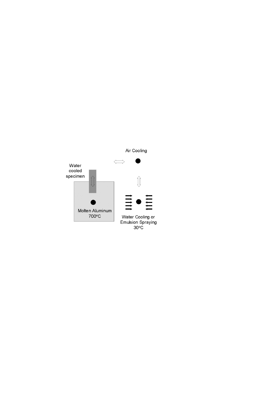
Figure 1.
Thermal fatigue testing apparatus
Heat and Surface Treatment of Hot-Work Tool Steels for Optimum In-Service Performance
81
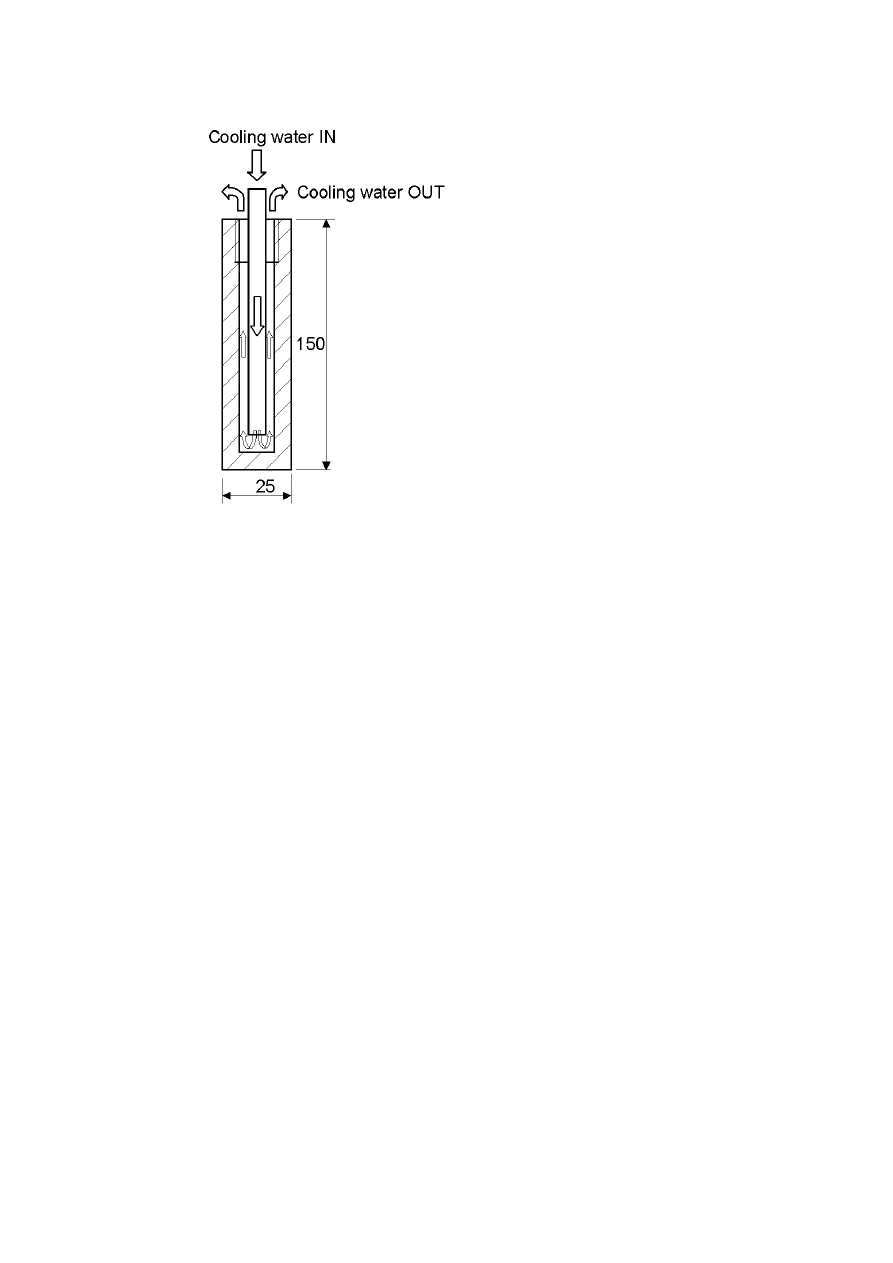
Figure 2.
Thermal fatigue sample
EXPERIMENTAL PROGRAM
A comprehensive test program is designed to study the material proper-
ties and resistance to thermal fatigue of Uddeholm Dievar, Orvar, QRO 90,
and Vidar subjected to different heat treatments and thermochemical surface
treatments. The austenitizing temperature and some particular quenching
and tempering parameters are studied for different heat treatment systems.
The surface nitriding and oxidation treatments are applied to some speci-
mens. Three test specimens are prepared for each heat and surface treat-
ment performed; a block of 15×55×60 mm is used to machine three Charpy
V-notch specimens and specimens for hardness and microstructure testing;
two 25×25×150 mm specimens for thermal fatigue testing are machined.

82
6TH INTERNATIONAL TOOLING CONFERENCE
After the heat treatment, the Charpy V-notch specimens are machined and
the impact testing performed. The hardness is measured and the microstruc-
tural characteristics are evaluated at the same specimens.
The thermal fatigue specimens are subjected to 16000 thermal cycles.
A program of inspection and evaluation is developed that defines the tests
performed every 4000 cycles. At 4000 cycles the specimens are inspected
for number of cracks and edge rounding at a pre-determined edge section.
At 8000 cycles, in addition to parameters evaluated at 4000 cycles, one of the
specimens is sectioned to inspect the average crack length, the microhardness
profile, and the microstructural characteristics of the material. At 12000
cycles, the same inspection as at 4000 cycles is performed. At 16000 cycles,
the second specimen is used for complete examination.
Temperature measurement is performed by thermocouples (TC) inserted
to 1.6 mm diameter holes drilled next to the inner and outer surface of the
specimen. The outer TC is positioned at the specimen edge with the center-
line at 1.2 mm from both outer surfaces, whereas the inner TC’s centerline
is also placed 1.2 mm from the inner specimen surface. Three specimens
were prepared with sets of holes to the depth of 70 mm, 90 mm, and 110
mm from the top specimen surface. The edge section between 70 and 110
mm, measured from the top of the specimen is the evaluation region for the
thermal fatigue cracking, edge rounding, and the microhardness profile.
THERMAL FATIGUE TESTING APPARATUS
Figure 1 shows the testing apparatus developed to simulate thermal cy-
cling conditions that occur at the surface of a high-pressure die-casting
(HPDC) die. The test specimen is immersed into molten aluminum at 700
◦
C ,
then cooled at air, and finally immersed into a water solution of graphite or
sprayed with an emulsion to prevent aluminum from attacking to the speci-
men surface. The duration of a typical cycle is between 30 and 40s; 8-12s of
immersion in aluminum, 2-4s of immersion in water or spraying, and 20-24
of air cooling. Four specimens are mounted simultaneously on a specially
designed fixtures connected to cooling system, providing a continuous in-
ternal cooling of the specimens. The specimen fixtures are fastened on a
plate driven by the pneumatic cylinders in vertical and horizontal direction,
so the furnace with molten aluminum and the basin with coolant/lubricant is
reached. The pneumatic system is controlled by a personal computer hav-

Heat and Surface Treatment of Hot-Work Tool Steels for Optimum In-Service Performance
83
ing the possibility to define the speed of each movement and the time of
permanence in the aluminum and the cooling bath.
Despite the lubrication of the test specimens, there is a tendency of the alu-
minum to attach to the specimen surface. This represented a serious problem
for the testing: (1) the aluminum attached on the surface sometimes formed
a relatively thick, pot-shaped attachment, that brought a certain amount of
water into the molten aluminum causing dangerous explosions, and (2) al-
though the aluminum attached remelted in each cycle, it significantly affects
the temperature gradient in test specimen. This is because the heat from
the aluminum bath is not transmitted to heat the specimen, but to melt the
aluminum attached on the surface. Such test is inefficient and can not be
evaluated using the established thermal fatigue criteria. To prevent this be-
havior, a system was developed to clean the aluminum from the specimen
surface at the time it leaves the aluminum bath.
Figure 2 shows the specimen, which is a 25×25 mm square section, 150
mm long with a 10 mm diameter axial hole to the depth of 140 mm. Inside
the hole is inserted a tube connected to the cooling circuit that brings the
cooling water of 20oC to the bottom of the test specimen. The water then
flows upward between the tube and the specimen inner wall and continuously
cools the inner specimen surface. This cooling assures the high temperature
gradient between the inner and the outer surface of the specimen while
in contact with molten aluminum. The high thermal gradient causes high
axial stresses that peak at the specimen edge. Finite elements are used to
calculate the temperature distribution in the specimen and the corresponding
axial stresses throughout the heating and cooling transient.
COMPUTATIONAL
THERMAL STRESS ANALYSIS OF THE SPECIMEN
A typical thermal cycle measured in the thermal fatigue test specimen
is modeled using the ABAQUS finite element code [11]. The objective of
modeling study is to determine the axial stresses in the specimen throughout
the heating and cooling transient. The stress transient represents a basis for
evaluation of thermal fatigue resistance of the material.
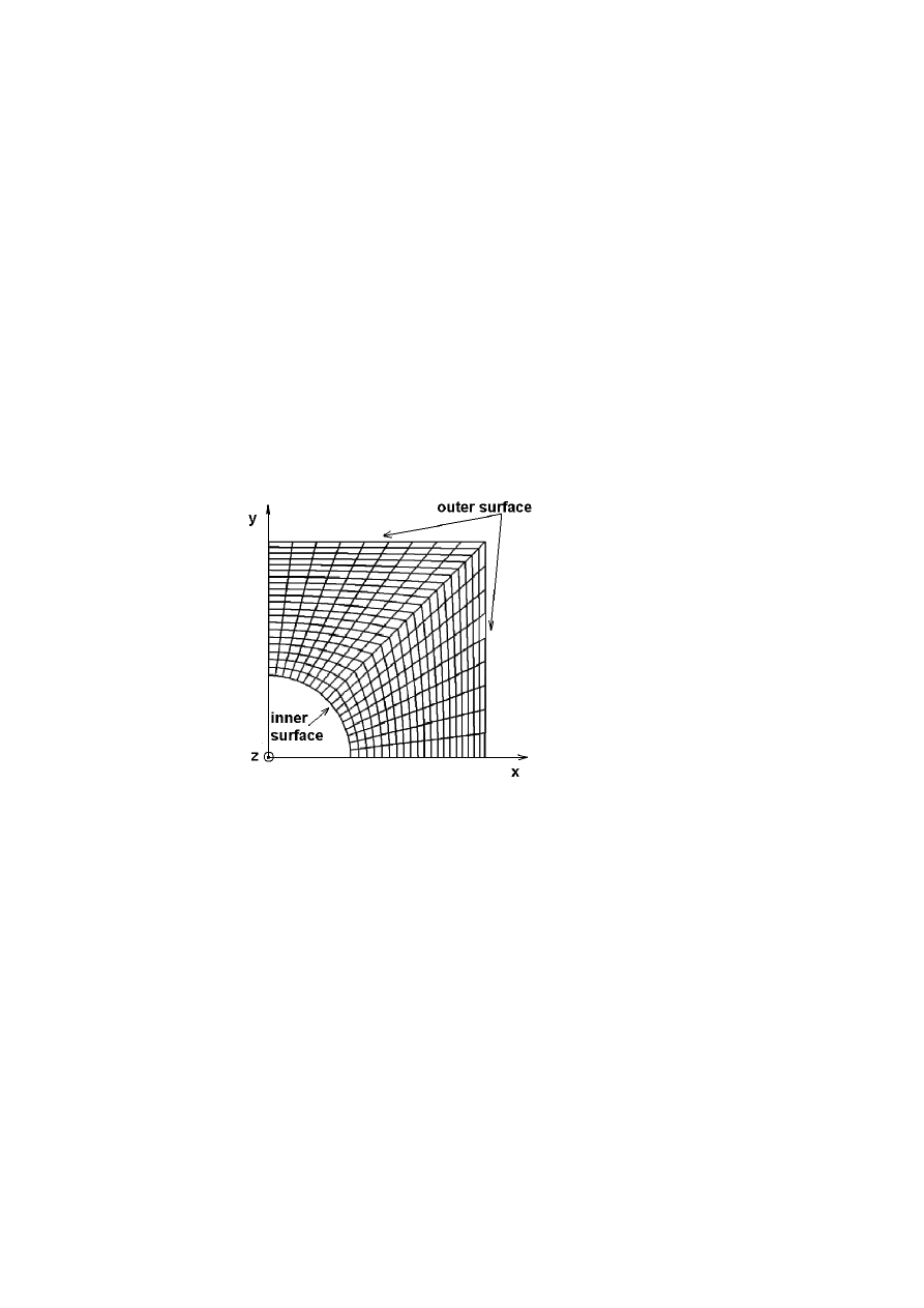
A 2D finite element model is developed of the specimen cross-section.
The model and the applied boundary conditions are shown in Fig. 3. The
Cartesian coordinate system is used with the origin in the center of the inner
84
6TH INTERNATIONAL TOOLING CONFERENCE
hole, and the geometric symmetry in both axes is considered. The section
is modeled with 360 linear eight-node elements. In mechanical analysis,
which is performed separately from the thermal, the corresponding plane-
strain elements were used.
The heat transfer coefficient between the specimen and the aluminum
bath, the air, and the emulsion fluid is computed based on the comparison
between the experimental and computational results. The computed heat
transfer coefficients are then used to calculate temperature distribution in
the specimen throughout the transient.
The mechanical analysis was performed in a separate run, uncoupled with
the thermal analysis. The elastic-plastic constitutive model was used and
the stress-strain curve was characterized by elastic modulus, the yield stress,
the ultimate stress and the elongation, thus defining the work hardening
properties of the material. A strain rate independent model with the Von
Mises yield criterion, isotropic hardening, and a Poisson’s ratio of 0.3 was
used in all analyses. Temperature dependent mechanical properties were
used in computations.
Figure 3.
The finite element mesh

Heat and Surface Treatment of Hot-Work Tool Steels for Optimum In-Service Performance
85
ANALYSIS OF THE TEMPERATURE CYCLES AT A
CRITICAL HPDC TOOL
In a separate study a thermal analysis of a critical HPDC die is performed
for the first 15 cycles of filling, solidification, die cooling and emulsion spray-
ing. Two different cases are studied: (1) the die is preheat to 200
◦
C before
the first cycle start, and (2) the first cycle starts without preheat, i.e. cold
start is performed. The temperatures are recorded at 16 different positions
in the die. At each position, the temperature is recorded at the surface, at 3
mm and at 6 mm below the surface. The surface temperature is recorded at
0.1 to 0.3 mm beneath the surface depending on the discretization density
of the finite-difference model established by the MAGMA Soft computer
code used in computations. The results are used to determine the severity of
temperature gradients at different locations in the die and to compare them
with the temperature gradients measured in thermal fatigue testing speci-
mens. This way the results of thermal fatigue testing can be used to make
predictions of in-service life of actual HPDC tooling.
RESULTS AND DISCUSSION
TEMPERATURES IN THE THERMAL FATIGUE
SPECIMEN
Temperature measurement in the thermal fatigue specimen is performed
at two different cooling regimes. In the first regime both the continuous cool-
ing with the cooling water inside the specimen and the intermediate cooling
achieved by 2-4s immersion of the specimen into the cooling basin are ap-
plied. In the second regime, only the continuous cooling inside the specimen
is applied. Figure 4(a) shows temperatures of a few cycles measured using
the two TCs at the outer and inner surface. The peak temperature measured
at the outer surface is 460
◦
C , whereas the maximum at the inner surface is
about 330
◦
C , giving a maximum through-thickness gradient of 130
◦
C (the
distance between the TCs is about 8 mm). The minimum cycle tempera-
ture is about 85
◦
C for both surfaces. The maximum temperature transient is
375
◦
C and 245
◦
C for outer and inner surface respectively. Figure 4(b) shows
the temperature measured for the case of inside cooling only. The tempera-
tures are higher: 500
◦
C at the outer surface, 370
◦
C at the inner surface, with
the minimum cycle temperature of 145
◦
C . The through-thickness gradient

86
6TH INTERNATIONAL TOOLING CONFERENCE
(a) both continuous inner and intermediate
outer water cooling
(b) only continuous inner water cooling
Figure 4.
Temperature transient in the test sample measured by two TCs positioned next
to the outer and inner surface
is about the same as in the first case, whereas the maximum temperature
difference is lower for both surfaces. Note that the TC’s centerline is po-
sitioned at about 1.2 mm beneath the surface, which means that the peak
temperature for the outer surface is higher, and lower for the inner surface.
The exact surface temperatures are to be calculated using the finite element
model developed.
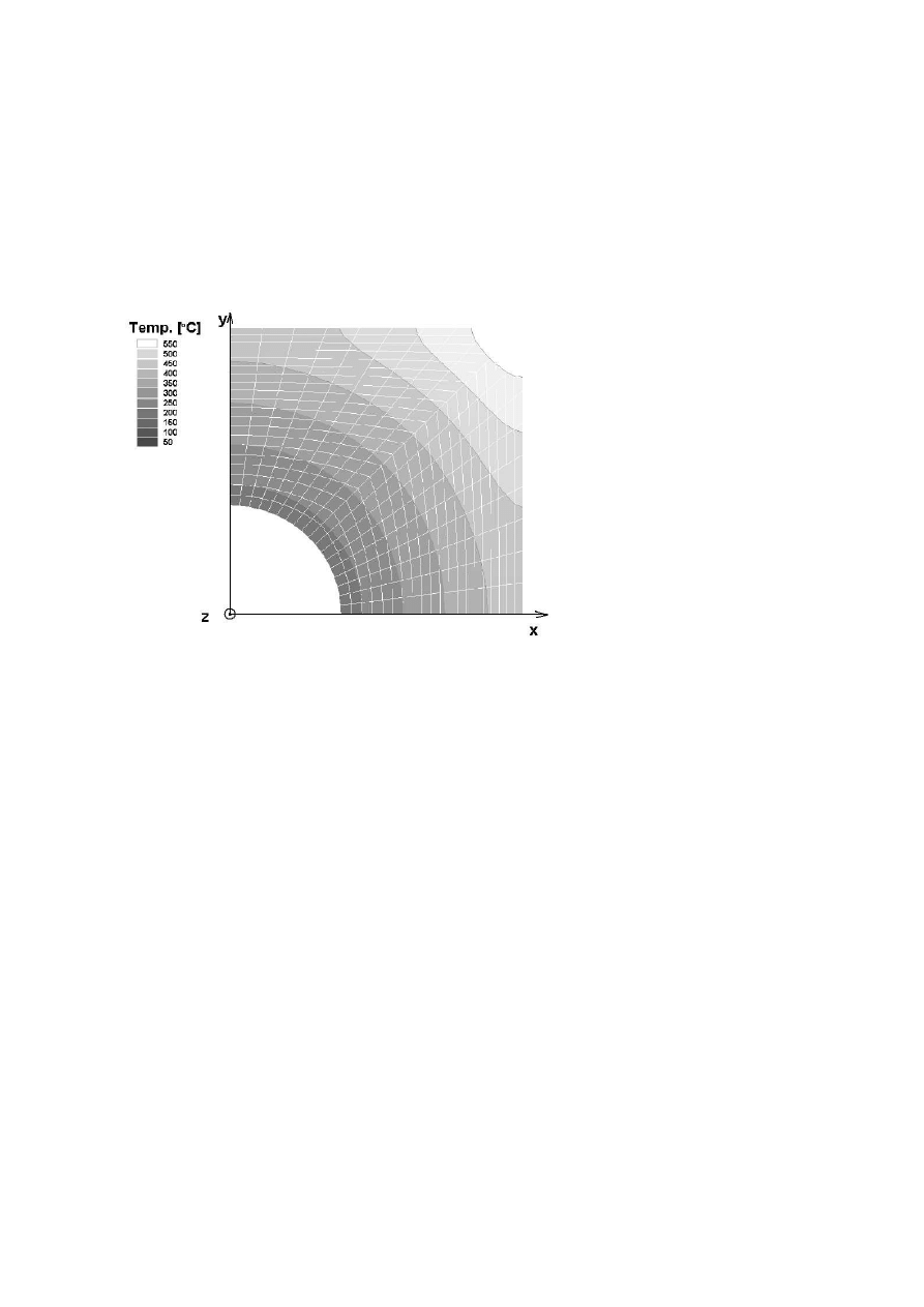
Figure 5 shows the temperature distribution in the cross-section of the
thermal fatigue specimen before exiting from molten aluminum. The high
temperature gradient between the outer surface and the inner surface causes
high axial stresses. The temperature at the outer surface edge is consid-
erably higher than in the rest of the outer surface. Therefore, the highest
axial stresses are expected at the outer surface edge (compressive when in
aluminum bath and tensile when in cooling bath), which is also the location
of the first cracking expected.
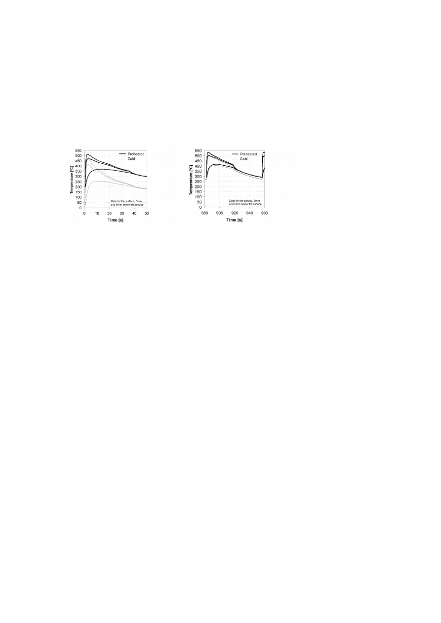
TEMPERATURES AT A HPDC DIE SURFACE
Figure 6(a) shows the temperatures at a critical location of a HPDC die
at the first temperature cycle. The temperatures are computed for cold-start,
which means the die is not preheated before stamping, and hot-start, where
the die is preheated to 200
◦
C . The temperatures are recorded at the surface,
3 mm and 6 mm below the surface at the exit from the feeding channel.
The maximum surface temperature is 470
◦
C and 515
◦
C for cold-start and
Heat and Surface Treatment of Hot-Work Tool Steels for Optimum In-Service Performance
87
Figure 5.
Temperature distribution in the thermal fatigue test sample before exiting from
the molten aluminum
88
6TH INTERNATIONAL TOOLING CONFERENCE
preheated die respectively. Figure. 6(b) shows the same temperatures for
the cycle number 14, where the die is already at in-service regime. This is
confirmed by the minimum effect of initial die preheat on the peak surface
temperature, which are for some 20
◦
C higher from the peak temperatures of
the first cycle.
(a) the first cycle for preheated and cold start
(b) cycle no. 14 for preheated and cold start
Figure 6.
Temperature transient in a HPDC die measured at the exit from feeding channel
at the surface, 3 mm and 6 mm below the surface
The detrimental effects of the cold-start are shown in Fig. 7(a), which
shows the temperature difference between the surface TC and the TC po-
sitioned 6 mm below the surface. The temperature gradient in the first 6
mm underneath the surface reaches 350
◦
C , which is 100
◦
C higher than the
temperature gradient of the first cycle made with the preheated die. Figure
7(b) shows that temperature gradient lowers to 200
◦
C when the die reaches
the stable in-service regime, regardless of the preheat temperature.
The conditions at this critical location compare very well to the condi-
tions at thermal fatigue test, bearing in mind that the temperature at the test
specimen is measured at 1.2 mm beneath the surface. The temperature cycle
computed at the exit from the feeding channel is extremely severe. Both
the peak temperature and the temperature gradient of all other locations
examined at the die are considerably less severe.

Heat and Surface Treatment of Hot-Work Tool Steels for Optimum In-Service Performance
89
(a)
(b)
Figure 7.
Temperature difference between the surface and 6 mm below the surface for:
(a) the first cycle presented at Fig. 6(a); (b) the cycle no. 14 presented at Fig. 6(b).
MECHANICAL AND METALLURGICAL
PROPERTIES
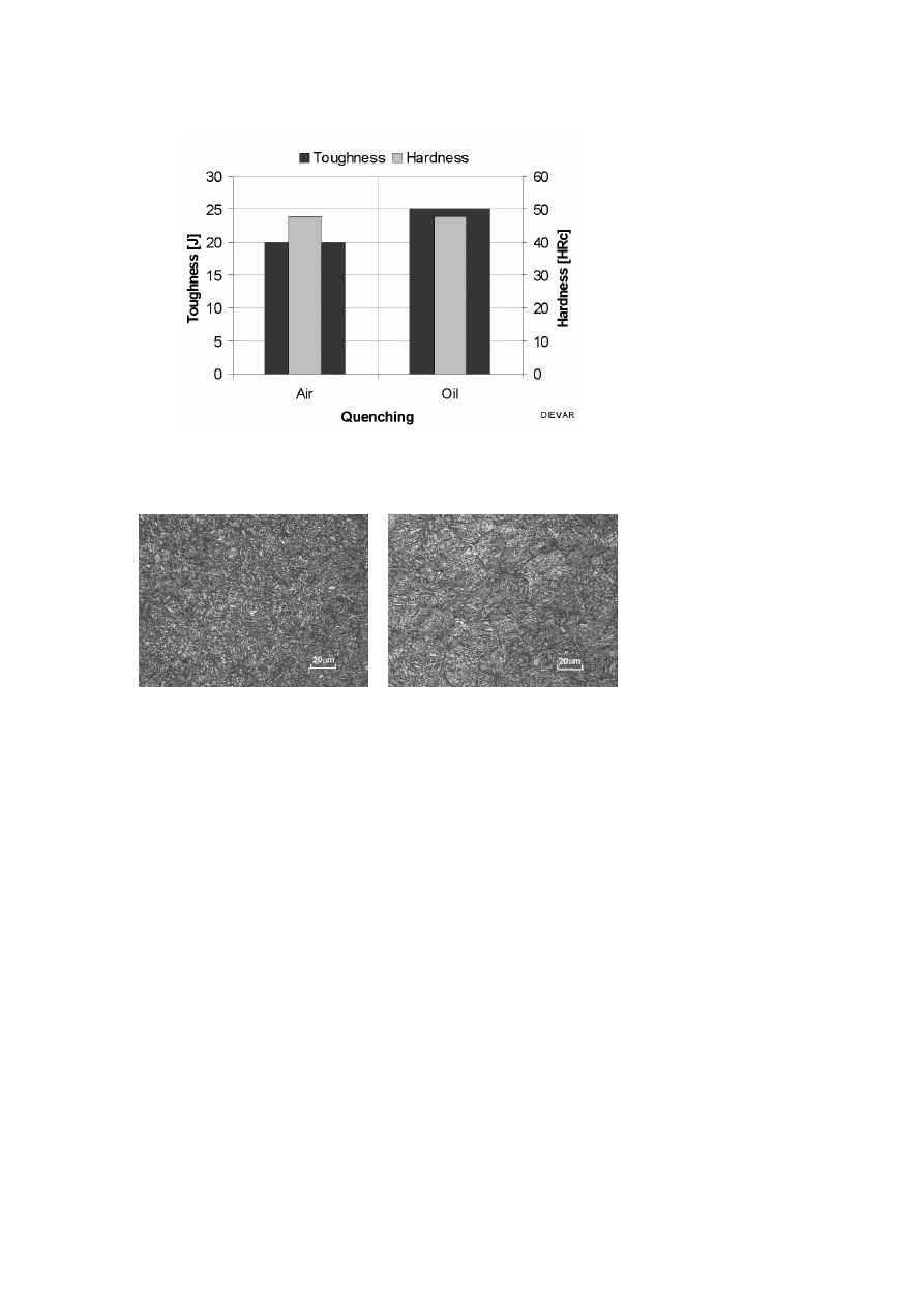
Figure 8 demonstrates the effect of quenching speed on the mechanical
properties of Dievar. The two specimens quenched in oil and in air are
tempered to the same hardness of 48 HRc. The toughness of the oil quenched
specimen is higher for 25%. A similar effect of the cooling speed is expected
on tempering resistance. The evaluation will be performed after completion
of thermal fatigue testing.
Figure 9(a) shows a homogenous martensitic microstructure of the speci-
men quenched in oil. Figure. 9(b) is a micrograph of the air cooled specimen
of Dievar. The difference between the two microstructures is obvious. The
coarse grain microstructure with evident grain boundaries of air cooled spec-
imen explains the lower toughness obtained.
THERMAL FATIGUE EVALUATION
At this stage a preliminary evaluation of thermal fatigue damage is per-
formed on an Orvar Supreme specimen after completion of 6000 cycles on
the thermal fatigue testing apparatus. As expected the cracking first appeared
along the specimen edge. The cracks are perpendicular to the specimen ax-
ial direction. Therefore, the cracking is caused by high axial stresses at the
specimen edge, which are the result of high through-thickness temperature
gradients and temperature cycling at the edge.
90
6TH INTERNATIONAL TOOLING CONFERENCE
Figure 8.
Hardness and toughness of Uddeholm Dievar subjected to different heat treat-
ment cycles
(a) subjected to rapid oil quenching
(b) subjected to air cooling. Nital 4% etch
Figure 9.
Micrograph showing the structure of Uddeholm Dievar
A series of parameters is used to evaluate the thermal fatigue resistance
of the materials studied. The parameters evaluated are: (1) the number of
cracks, (2) edge rounding, (3) average crack depth, (4) microhardness profile
from the surface. The parameters are evaluated along a 40 mm segment of
the edge, between 70 mm and 110 mm from the specimen top side.

Heat and Surface Treatment of Hot-Work Tool Steels for Optimum In-Service Performance
91
Figure 10(a) shows the specimen sectioned in transverse direction to eval-
uate the edge rounding. Note the 0,1 mm deep region of the edge material
that is severely damaged by thermal fatigue and exposure to high temper-
atures. Exposure to high temperatures resulted in a tempered structure of
a hardness inferior to that of the original specimen. The microhardness
measured at the damaged edge region is 410 HV
0
.
2
, at the distance of 0,1
mm from the surface is at 470 HV
0
.
2
, whereas at 0,2 mm the microhardness
equals to that of original material which is 550 HV
0
.
2
.
Figure 10(b) shows cracking along the specimen edge sectioned in axial
direction. At this stage an average of 10 cracks per millimeter are found with
the length between 10 and 300 µm, and the average crack length of 69 µm.
Figure 10(c) shows a preferential transgranular cracking not affected by
the microstructural characteristics of the material. The crack propagates in
a direction perpendicular to the specimen surface. Figure. 10d shows the
tip of the same crack at higher magnification.
CONCLUSIONS
A comprehensive test program is designed to study the material properties
and resistance to thermal fatigue of Uddeholm hot-work tool steels subjected
to different heat treatments and thermochemical surface treatments. The re-
sults of a preliminary evaluation of Dievar specimens show a 25% higher
toughness for the case of rapid oil-cooling with respect to slow air cool-
ing at the same hardness level. The microstructure analysis confirms the
mechanical property results.
An apparatus is made to perform thermal fatigue testing by immersion to
molten aluminum of specially designed specimens with a continuous inter-
nal water cooling. A preliminary testing is performed and thermal fatigue
resistance of a specimen is evaluated using a series of parameters; number
of cracks, average crack length, specimen edge rounding and microhardness
profile.
Temperature measurement at different locations in the thermal fatigue
specimen is performed at two different cooling arrangements. The measured
temperature transient are used in development and verification of finite el-
ement model used to analyze the stresses in the specimen throughout the
thermal transient.
A thermal analysis of a critical HPDC die is performed by a commercial
computer code. Temperatures are recorded at a number of locations at the

92
6TH INTERNATIONAL TOOLING CONFERENCE
(a) edge rounding and cracking
(b) typical cracks at specimen edge sectioned
in axial direction
(c) a typical crack at specimen edge, 4% Nital
etch
(d) tip of a typical crack at specimen edge,
Fry’s solution etch
Figure 10.
Micrographs used for evaluation of damage caused by thermal cycling after
5000 cycles

Heat and Surface Treatment of Hot-Work Tool Steels for Optimum In-Service Performance
93
die surface. The temperature gradient underneath the die surface is also
analyzed. Two startup regimes are studied: (1) cold start, and (2) start
with die preheated to 200
◦
C . The results are used to compare the thermal
conditions in the thermal fatigue specimen with conditions at an actual die
working-surface. The results reveal detrimental effects of the cold-start on
the die material.
The evaluation of a thermal fatigue test specimen at 6000 cycles show
numerous transgranular cracks of an average length of 69 µm, propagating
perpendicularly into the material. The test thermal conditions correspond
to those at critical spots at the die working surface. Note that the thermal
fatigue specimen is not subjected to pressure nor the wear of high-velocity
aluminum flow.
ACKNOWLEDGMENTS
This research was sponsored in part STEEL Group, Motta di Livenza
(TV). The research was also sponsored by the Slovenian Ministry of Science
and Technology.
REFERENCES
[1] NADCA 207-97 Recommended Procedures H-13 Tool Steel, NADCA (1997)
[2] GM DC-9999-1, GM Powertrain, Bedford OH, (1999)
[3] J. W. Wallace, D. Schwam, Die Casting Engineer, May/June (2000), p.50-58
[4] P. Roche, O. Sandberg, O. Yucel, Proc. 5th Int.Conf.Tooling, Leoben, Austria (1999),
p.475-484
[5] B. Edenhofer, Heat treatment of Metals, 1999.1, p.1-5
[6] S. Denise, P. Archambault, E. Gautier, A. Simon, G. Beck, Proc. Third
Int.Conf.Quenching and Control of Distortion, Prague, Czech Republik (1999), p.263-
276
[7] B. L. Ferguson, G. J. Petrus, T. Pattok, Proc. 3rd Int.Conf.Quenching and Control of
Distortion, Prague, Czech Republik (1999), p.188-200
[8] D. Shick, et al., Proc. Second Int. Conf. Quenching and Control of Distortion, Cleveland
OH, 1996, p.357-365
[9] D. Klobcar, B. Taljat, J. Tusek, G. Scavino, proc. Second European Congress Heat and
Surface Treatment, Rimini, Italy, 2001, pp.261-270
[10] J. Tusek, B. Taljat, P. Boscarol, B. Jez, A. Kosnik, "An Apparatus for Thermal Fatigue
Testing of Steels Used in Pressure Die-Casting Tooling, to be published.
[11] ABAQUS Users’ Manual, Version 5.8, Hibbitt, Karlsson & Sorensen (1999)
Wyszukiwarka
Podobne podstrony:
Best Available Techniques for the Surface Treatment of metals and plastics
50 707 719 Thermal Fatique and Softening Behaviour of Hot Work Steels
8 95 111 Investigation of Friction and Wear Mechanism of Hot Forging Steels
65 935 946 Laser Surface Treatment of The High Nitrogen Steel X30CrMoN15 1
Corrosion behavior and surface characterization of titanium
Synthesis and Surface Reactivity of Organometallic Nanoparticles 233 260
51 721 736 Evaluation of the Cyclic Behaviour During High Temperature Fatique of Hot Works
Energetic and economic evaluation of a poplar cultivation for the biomass production in Italy Włochy
Effect of heat treatment on microstructure and mechanical properties of cold rolled C Mn Si TRIP
The Structure and Heat Treatment of Low Carbon Steel
Magnetic Treatment of Water and its application to agriculture
Drying, shrinkage and rehydration characteristics of kiwifruits during hot air and microwave drying
52 737 754 Relationship Between Microstructure and Mechanical Properts of a 5%Cr Hot Works
więcej podobnych podstron