New Transducer technology… 106
th
AES Convention Munich 1999 page 1 /11
Klaus Heinz, ADAM Professional Audio Berlin
106. AES Convention Munich 1999
Klaus Heinz
A.D.A.M. Professional Audio Berlin
New transducer technology A.R.T. = Accelerated Ribbon Technology
- evolution of the air motion transformer principle
Abstract
The paper describes new high- and mid-frequency loudspeaker drive units, based
on the air motion transformer idea of Dr. Oskar Heil. Improvements concern geo-
metrical layout as well as the use of new materials like capton-aluminium dia-
phragms and neodyme magnets. The membranes are made of very thin and es-
pecially folded diaphragms that are mounted in a strong magnetic field. They do
not move air in a piston like action in a 1:1 ratio, but with a 4:1 diaphragm to air ve-
locity transformation, thus improving transient response and dynamics of the system.
Design details and measurement results are presented.
Based on the original works of Dr. Oskar Heil, who invented his “Air Motion Transformer” back in
1964, A.D.A.M. Professional Audio Berlin developed new tweeters and midrange units who are
based on improved layouts and new materials.
As not everybody in the audience might be familiar with the principle under consideration I first in-
troduce the fundamental kinematics, that set the air motion transformer apart from practically all
the rest of electrodynamic or electrostatic transducers. Instead of using a piston like action to
move air forth and back in a 1:1 ratio, the air motion transformer squeezes air in and out, thus
achieving an estimated 4:1 velocity ratio between driving diaphragm and driven air.
It does so by using a folded diaphragm, that carries rectangular aluminium stripes, a device similar
to what is used in magnetostatic transducers. This foil however is folded and brought into a strong
magnetic field, leading to a diaphragm-air motion kinematic that can be seen here:
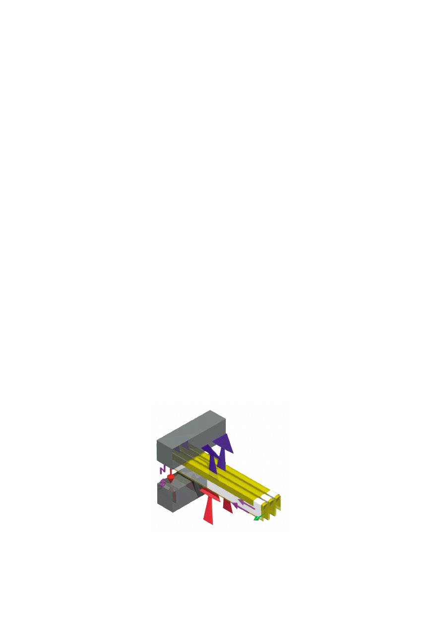
1: The Air Motion Transformer principle
New Transducer technology… 106
th
AES Convention Munich 1999 page 2 /11
Klaus Heinz, ADAM Professional Audio Berlin
Imagine this to be the position at the maximum of a positive sine half wave: the upper arrows show
the air squeezed out, the lower arrows represent the air to be sucked in. At the zero crossings there
will be equal distances between the folds, with no resulting air pressure. The maximum of a nega-
tive sine half wave will cause corresponding air pressure with all indicating arrows showing into the
opposite direction. Because the folds are deeper than they are wide, the 4:1 velocity ratio men-
tioned above is achieved.
Compared to the original approach the design goals for the new drive units have been to
-
build monopole units that can be built into “normal” speaker cabinets
-
have no magnetic structure around the diaphragm with dimensions comparable
to the wavelength of the higher frequencies transmitted
-
have dispersion figures similar to 1” tweeters and 4” midrange units respectively and
-
improve power handling.
Moreover, better materials and processes were to be found that show little tolerances only and
make it possible to build units on a reliable basis. The new transducers have been named A.R.T. =
Accelerated Ribbon Technology loudspeakers.
Tweeter
To obtain the results mentioned above new dimensions have been chosen, that are possible now
after the arrival of neodyme magnets. As an orientation the area of a normal 1” dome tweeter was
kept in mind. The air gap in this case is by far wider and deeper than usual with voice coil based
systems; the demand for the total flux is immense. Even worse, where the induction has to come
from, the air wants to go in and out. Good compromises had to be found to fulfil both needs.
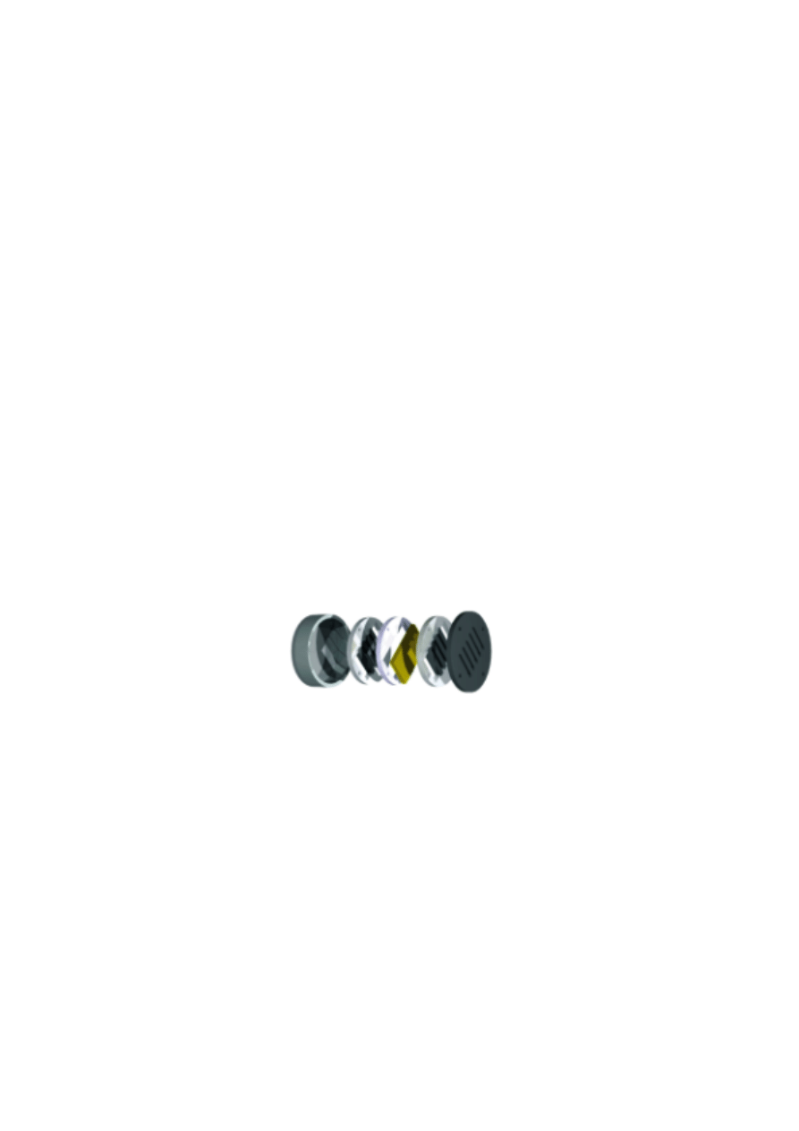
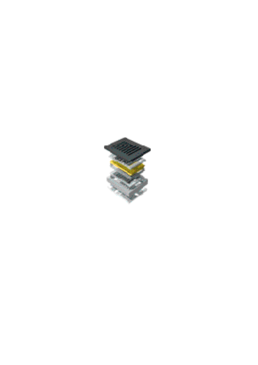
2: mechanical construction of the tweeter
Rows of front-back polarised neodyme magnets are positioned on both sides of the diaphragm.
Front and back plate together with the surrounding capsule build the yoke. The magnetic circle is
completely closed, practically no stray fields are observed, so the unit can be used near to CRT’s.
The diaphragm consists of a capton – aluminium laminate, created by a purely physical heat-pres-
sure process. It can withstand temperatures of up to 400 °C, thus improving the power handling
and dynamic capabilities of the unit considerably.
An additional benefit of the folding is the fact, that the acoustically effective area is much bigger
than the “mouth” of the unit, where the sound waves are emitted. Not the complete area is acous-
tically effective of course, yet a 2.5:1 ratio between the area of a 1” dome tweeter and the A.R.T.
tweeter is obtained.
New Transducer technology… 106
th
AES Convention Munich 1999 page 3 /11
Klaus Heinz, ADAM Professional Audio Berlin
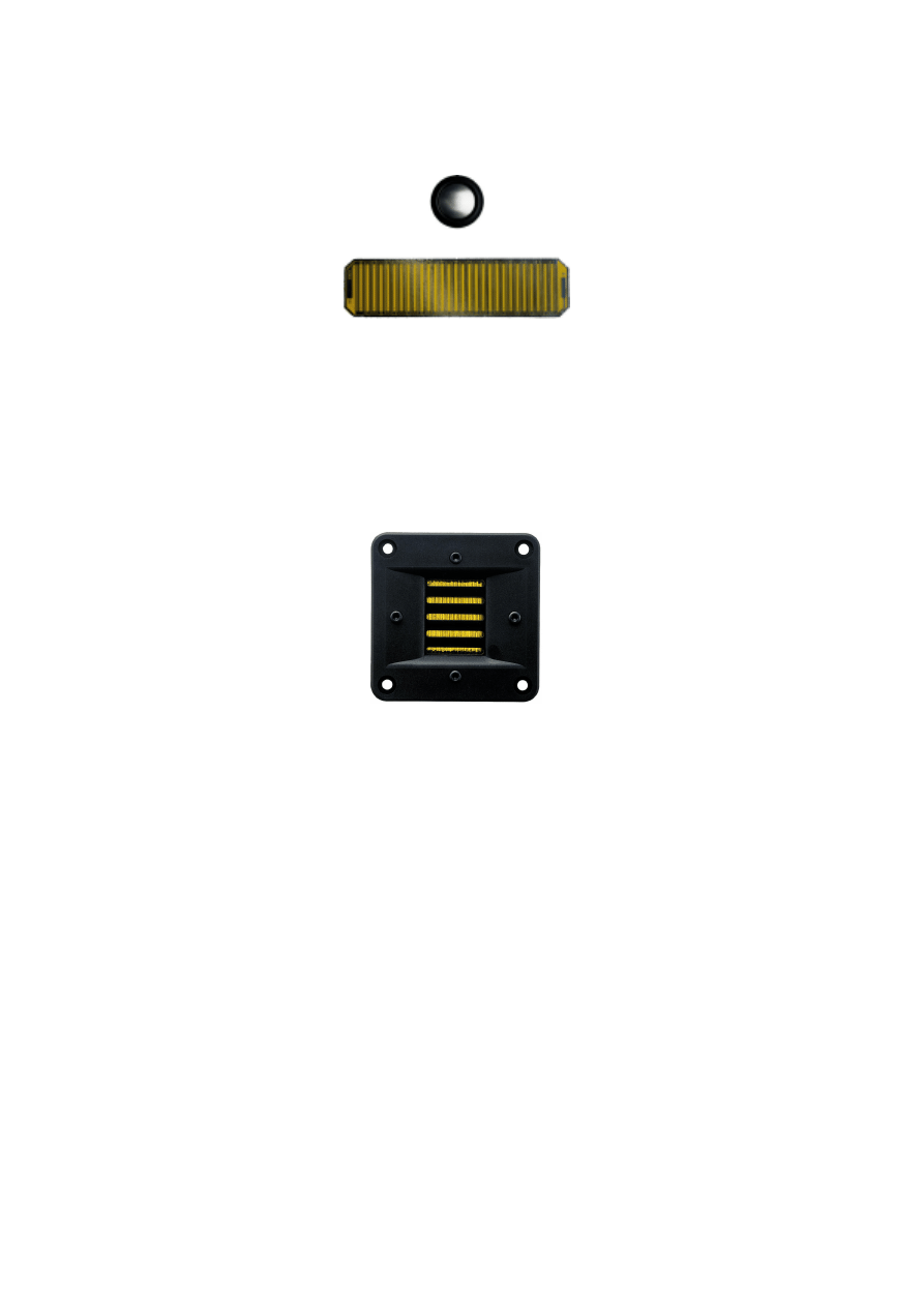
3: effective diaphragm areas of a 1” dome tweeter (above) and the A.R.T. tweeter.
The diaphragm is manually folded and glued to its carrying frame.
It was of special interest to bring the resonance frequency of the tweeter down to 1.5 kHz. Thus a
successful integration within 2-way systems would be possible. An additional volume behind the
diaphragm was attached, carefully damped for linear behaviour of the system.
The magnetically closed tweeter is mounted to a plastic front plate and is shown here:
Abb. 4: The completed A.R.T. tweeter
Electroacoustic behaviour of the tweeter: the measurements.
Frequency response
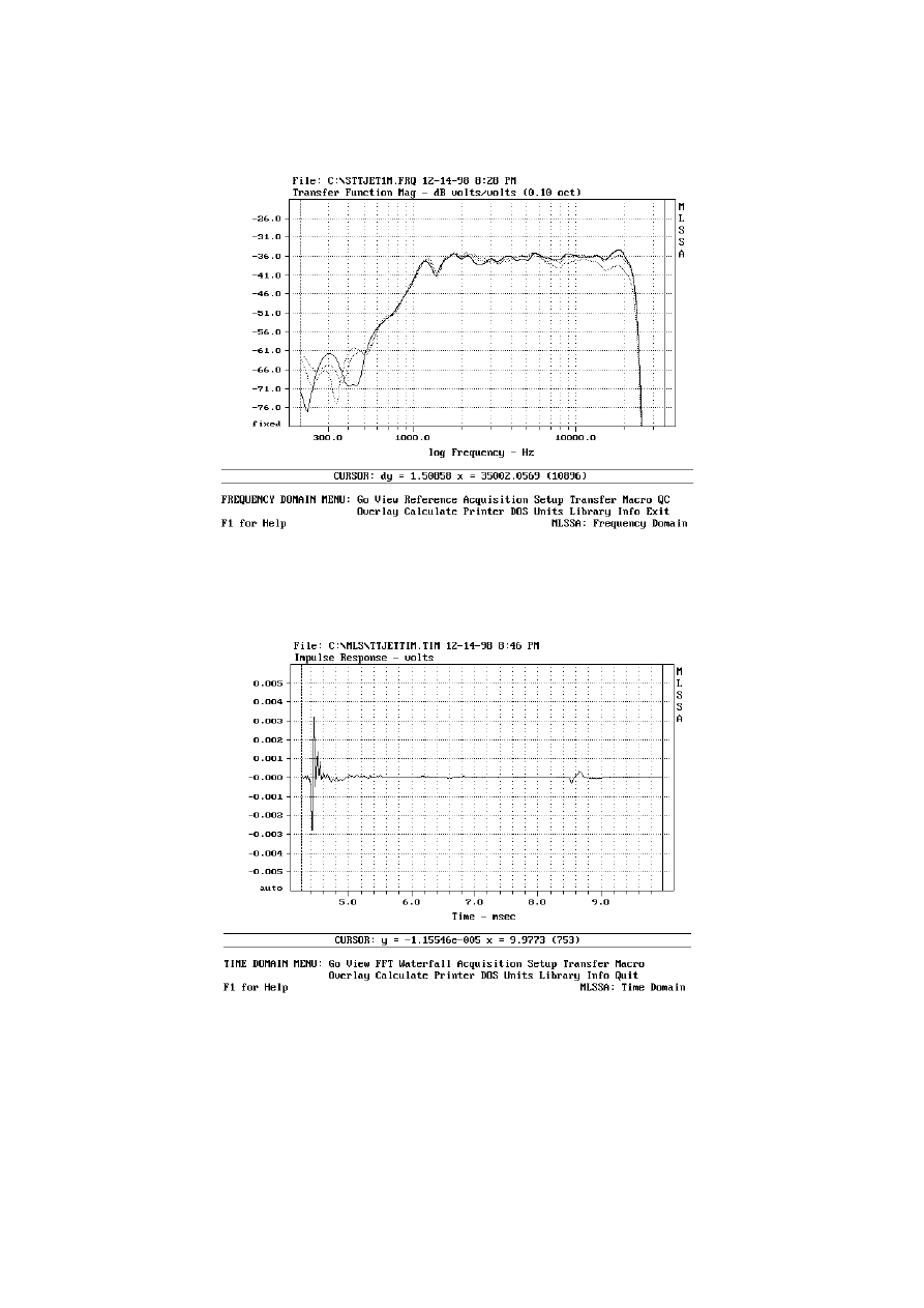
The measurement has been taken with the tweeter built into our S2 studio monitor. Microphone dis-
tance has been 1m; the three curves show the behaviour in different angles.
New Transducer technology… 106
th
AES Convention Munich 1999 page 4 /11
Klaus Heinz, ADAM Professional Audio Berlin
5: frequency response, microphone 1m, angles 0°, 15° and 30°
Impulse response
shows a quick decay of the energy within the first millisecond. The signal at 8.6 ms is a first reflection
of course.
6: Impulse Response, microphone distance 1m
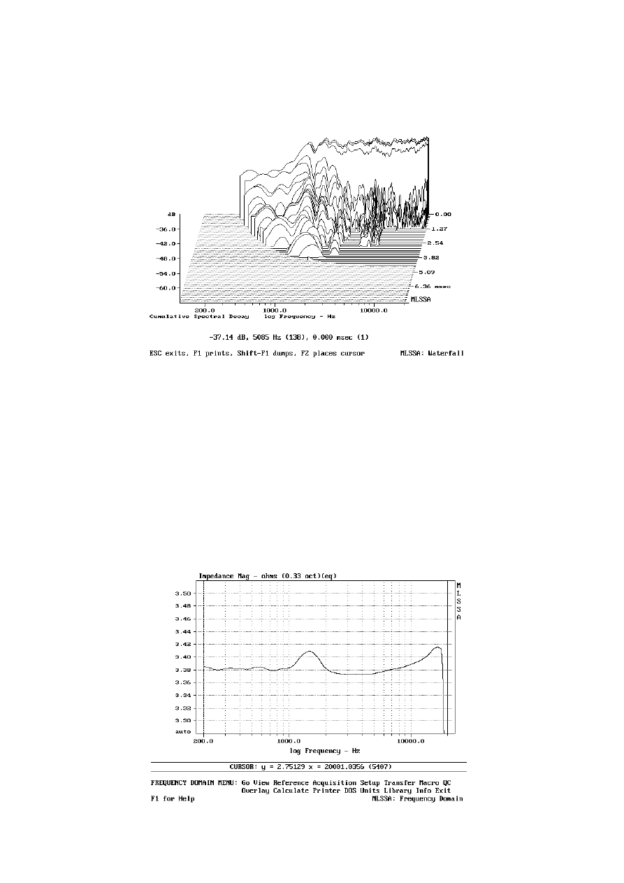
Cumulative Decay Spectrum
New Transducer technology… 106
th
AES Convention Munich 1999 page 5 /11
Klaus Heinz, ADAM Professional Audio Berlin
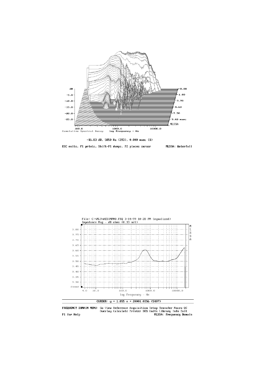
7: Cumulative Decay Spectrum from the above measurement
A typical delayed oscillating around the resonance frequency of 1.5 kHz is normal and will not play
a role, because of the separating networks.
The first 30 dB of decay are very fast, within half a millisecond approximately, and as they are deci-
sive for the perception of sound a superior transient reproduction can be expected.
The decay around 6 kHz goes on for another two milliseconds, and although it is vastly reduced in
level already it remains a disliked property.
Impedance
As there is no voice coil the impedance curve is a flat line using normal scaling. To show the weak
resonance of the system the following plot is useful:
New Transducer technology… 106
th
AES Convention Munich 1999 page 6 /11
Klaus Heinz, ADAM Professional Audio Berlin
8: Impedance (note vertical scale from 3,3
Ω
to 3.5
Ω
only!)
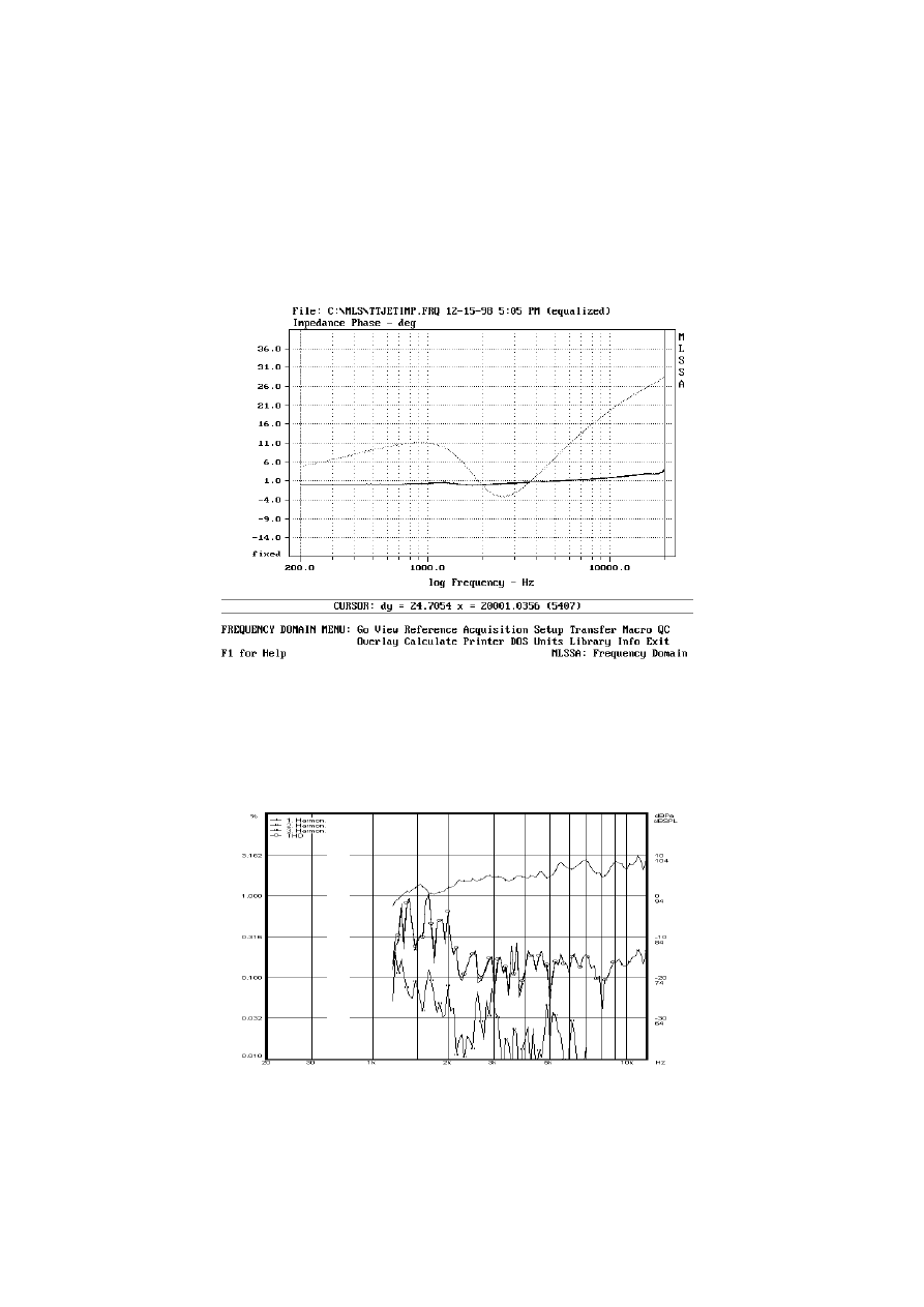
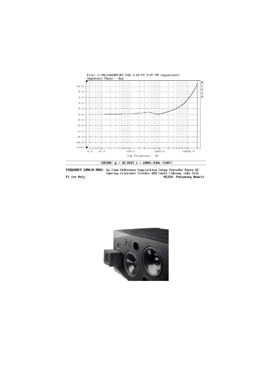
Phase
The phase consequently is a flat line too, and it is plotted here together with the phase response of
a typical 1” dome tweeter:
9: Phase comparison A.R.T tweeter / 1” dome
Distortion
Harmonic Distortions have been measured separately for the different components; THD is shown
as well:
10: Harmonic distortions: 2
nd
and 3
rd
harmonic plus. THD
The second harmonic plus THD remain below 0.2%, above 2 kHz, the more dangerous 3rd harmonic
is around 0,03 %. Higher order distortions (up to n=7) have been measured and always were less
New Transducer technology… 106
th
AES Convention Munich 1999 page 7 /11
Klaus Heinz, ADAM Professional Audio Berlin
than 1/10th of these values. The results obtained are comparable to those of very good 1” dome
tweeters.
All in all we have a tweeter that actually can replace a 1” dome, because its dimensions and dis-
persion are comparable. However, within the A.R.T tweeter a much larger diaphragm moves air in
a 4:1 velocity ratio, having superior power handling and dynamic capabilities. Linear phase re-
sponse and ultrafast decay behaviour can be measured.
The A.R.T. Midrange Unit
After finishing the tweeter it was an invitation of course to apply the new technique to a midrange
unit as well.
As it could be expected, the geometry of the folds had to be enlarged to appropriate dimensions.
As with the tweeter, a comparable voice coil driven speaker has been chosen, a 4” cone mid-
range in this case, that could be replaced, and whose dimensions gave the geometrical limits for
the unit.
11: mechanical construction of the midrange unit
Upcoming problems have been a once more drastically enlarged air gap. Depth and width of
such a unit make it difficult to get a very high total flux, which is necessary to have the efficiency
needed in modern systems. An array of 28 neodyme magnets with 8mm depth is necessary to
achieve this goal. The now rather big diaphragm had to be coated to avoid foil resonances.
The benefits however are very convincing. The folding results in an extremely wide frequency
band, and the unit reached responses from 200 Hz to well beyond 20 kHz with uncoated dia-
phragms. To concentrate on mid frequencies thicker and more stable laminates had been chosen,
with higher repulsing forces and therefore a higher resonance frequency. The coating lead to
higher SPL´s, but cost the area above 12 kHz, which we decided to be of minor interest for a mid-
range unit.
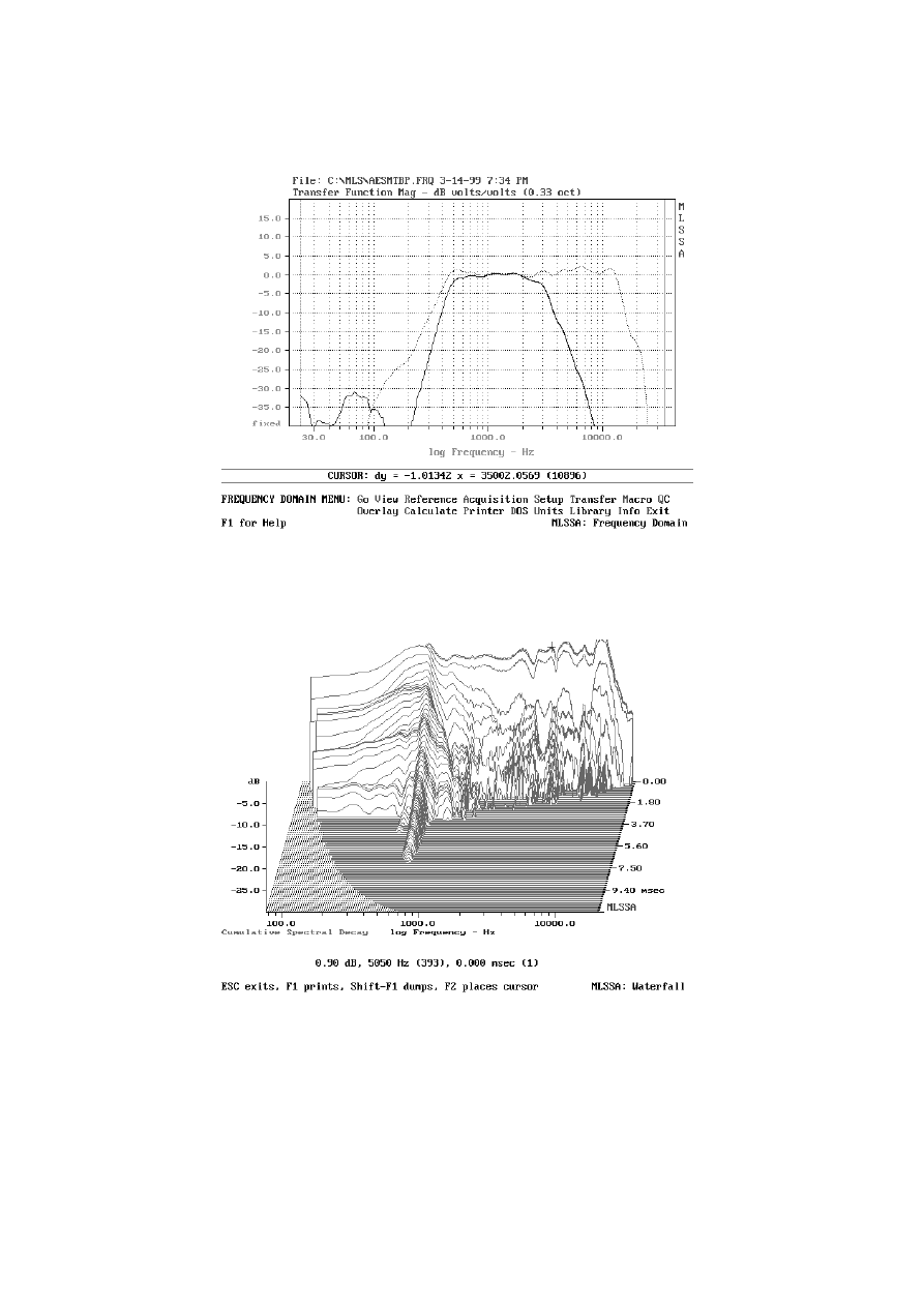
Frequency response
is measured with the unit built into the S4 Monitor. A bandpass filter with 500 Hz and 3 kHz is corner
frequencies is applied for integrating the units in the ADAM studio monitors:
New Transducer technology… 106
th
AES Convention Munich 1999 page 8 /11
Klaus Heinz, ADAM Professional Audio Berlin
12: frequency response of unfiltered and bandpass filtered A.R.T- midrange unit
The waterfall diagram of the unfiltered version shows a very fast decay within the band transmitted,
however a small resonance can be seen around 500 Hz:
4: cumulative decay spectra of the unfiltered A.R.T. midrange unit
The cumulative decay spectra of the filtered version show that the relevant energy has disap-
peared after 3 ms, including the resonance mentioned before:
New Transducer technology… 106
th
AES Convention Munich 1999 page 9 /11
Klaus Heinz, ADAM Professional Audio Berlin
13: cumulative decay spectra of the bandpass filtered A.R.T. midrange unit
Impedance
Similar to what was found with the tweeter, the impedance of the midrange unit is extremely flat,
showing a minimal dip around the resonance frequency:
14: Impedance of built in A.R.T- midrange unit (note vertical scale from 3,3
Ω
to 3.8
Ω
only!)
New Transducer technology… 106
th
AES Convention Munich 1999 page 10 /11
Klaus Heinz, ADAM Professional Audio Berlin
Consequently again the phase response is flat as well. There is no literature known to the author
presuming that a ± 1° phase shift can cause audible effects:
15: Phase response of the built in A.R.T- midrange unit
Decoupling the midrange cabinet: to optimise the reproduction capabilities of the unit it is moun-
ted in its own cabinet within the loudspeaker enclosure, swimming on a damping foam:
16: A.D.A.M. studio monitor with separately damped cabinet for the midrange unit
Conclusion
A new generation of transducers has been developed that move air in a different way compared
to the piston like actions of voice coil based systems. Yet all classical engineering aspects have
been observed: frequency response is linear in a wide range, dispersion is comparable to 1” domes
and 4” cone midrange speakers respectively, and efficiency is high for the tweeter (93 dB/W/m)
and reasonable for the midrange unit (89 dB/W/m). Impedance curves are flat 3.3
Ω
± 0.2
Ω
, phase
response consequently is ultralinear and distortion is on a very low level.

New Transducer technology… 106
th
AES Convention Munich 1999 page 11 /11
Klaus Heinz, ADAM Professional Audio Berlin
The obtained sound quality normally is acknowledged for its better transient response and more
exact spatial information. The proof of course is in the listening.
Wyszukiwarka
Podobne podstrony:
ICAO ANNEX 2 RULES OF THE AIR
Multistage evolution of the gra Nieznany
Geodynamic evolution of the European Variscan fold belt
Evolution of the Microstructure of Dynamically Loaded Materials
Peter S Beagle The Folk of the Air
The Evolution of the Long Necked Giraffe wolf ekkehard lonnig
New ideas in cars of the future
War In Heaven A Completely New And Revolutionary Conception of The Nature of Spiritual Reality by K
The Evolution of the Armored Force, 1920 1940
The Evolution of the Computer Virus
The evolution of the slavic be(come) type compound future
Properties Of The Classical Fourier Transform, Some Examp
The Mission of The One Star Transforming Planet Earth to Planet Star by Alloya N Huckfield (2003)
An Examination of the Evolution of Army and Air Force
Computer Viruses The Technology and Evolution of an Artificial Life Form
Blanchard European Unemployment The Evolution of Facts and Ideas
fitopatologia, Microarrays are one of the new emerging methods in plant virology currently being dev
więcej podobnych podstron