
Funktionsgenerator KSS5.1 08.02.00 en
1 of 28
SOFTWARE
KR C...
Function Generator
System Tech (KSS) 5.1

2 of 28
Funktionsgenerator KSS5.1 08.02.00 en
e
Copyright
KUKA Roboter GmbH
This documentation or excerpts therefrom may not be reproduced or disclosed to third parties without the express permission of the publishers.
Other functions not described in this documentation may be operable in the controller. The user has no claim to these functions, however, in
the case of a replacement or service work.
We have checked the content of this documentation for conformity with the hardware and software described. Nevertheless, discrepancies
cannot be precluded, for which reason we are not able to guarantee total conformity. The information in this documentation is checked on a
regular basis, however, and necessary corrections will be incorporated in subsequent editions.
Subject to technical alterations without an effect on the function.
PD Interleaf

3 of 28
Funktionsgenerator KSS5.1 08.02.00 en
Contents
1
Characteristics, functional description
5
. . . . . . . . . . . . . . . . . . . . . . . . . . . .
1.1
Characteristics
5
. . . . . . . . . . . . . . . . . . . . . . . . . . . . . . . . . . . . . . . . . . . . . . . . . . . . . . . . . . . . . . . .
1.2
Functional description
6
. . . . . . . . . . . . . . . . . . . . . . . . . . . . . . . . . . . . . . . . . . . . . . . . . . . . . . . . . .
1.2.1
Basic principle
6
. . . . . . . . . . . . . . . . . . . . . . . . . . . . . . . . . . . . . . . . . . . . . . . . . . . . . . . . . . . . . . . . .
1.2.2
Function definition
6
. . . . . . . . . . . . . . . . . . . . . . . . . . . . . . . . . . . . . . . . . . . . . . . . . . . . . . . . . . . . .
1.2.3
Correction direction
7
. . . . . . . . . . . . . . . . . . . . . . . . . . . . . . . . . . . . . . . . . . . . . . . . . . . . . . . . . . . .
1.2.4
The correction coordinate system TTS
7
. . . . . . . . . . . . . . . . . . . . . . . . . . . . . . . . . . . . . . . . . . . .
1.3
Configuration
8
. . . . . . . . . . . . . . . . . . . . . . . . . . . . . . . . . . . . . . . . . . . . . . . . . . . . . . . . . . . . . . . . . .
2
Programming, parameterization
9
. . . . . . . . . . . . . . . . . . . . . . . . . . . . . . . . . . .
2.1
Structure variables
9
. . . . . . . . . . . . . . . . . . . . . . . . . . . . . . . . . . . . . . . . . . . . . . . . . . . . . . . . . . . . .
2.1.1
$TECH[i], $TECH_C[i], i=1,...,6
9
. . . . . . . . . . . . . . . . . . . . . . . . . . . . . . . . . . . . . . . . . . . . . . . . . .
2.1.2
$TECHIN[i], i = 1,...,6
14
. . . . . . . . . . . . . . . . . . . . . . . . . . . . . . . . . . . . . . . . . . . . . . . . . . . . . . . . . . .
2.1.3
$TECHPAR[i, j], i=1,...,6 , j=1,...,10
14
. . . . . . . . . . . . . . . . . . . . . . . . . . . . . . . . . . . . . . . . . . . . . . .
2.1.4
$TECHPAR_C[i, j], i = 1,...,6 , j=1,...,10
14
. . . . . . . . . . . . . . . . . . . . . . . . . . . . . . . . . . . . . . . . . . .
2.1.5
$TECHVAL[i], i = 1,...,6
15
. . . . . . . . . . . . . . . . . . . . . . . . . . . . . . . . . . . . . . . . . . . . . . . . . . . . . . . . .
2.1.6
$TECHSYS
15
. . . . . . . . . . . . . . . . . . . . . . . . . . . . . . . . . . . . . . . . . . . . . . . . . . . . . . . . . . . . . . . . . . .
2.1.7
$TECHSYS_C
15
. . . . . . . . . . . . . . . . . . . . . . . . . . . . . . . . . . . . . . . . . . . . . . . . . . . . . . . . . . . . . . . . .
2.1.8
$TECHANGLE
15
. . . . . . . . . . . . . . . . . . . . . . . . . . . . . . . . . . . . . . . . . . . . . . . . . . . . . . . . . . . . . . . .
2.1.9
$TECHANGLE_C
15
. . . . . . . . . . . . . . . . . . . . . . . . . . . . . . . . . . . . . . . . . . . . . . . . . . . . . . . . . . . . . .
2.1.10
$TSYS
15
. . . . . . . . . . . . . . . . . . . . . . . . . . . . . . . . . . . . . . . . . . . . . . . . . . . . . . . . . . . . . . . . . . . . . . .
2.1.11
$DISTANCE
15
. . . . . . . . . . . . . . . . . . . . . . . . . . . . . . . . . . . . . . . . . . . . . . . . . . . . . . . . . . . . . . . . . . .
2.2
Analog sensors
17
. . . . . . . . . . . . . . . . . . . . . . . . . . . . . . . . . . . . . . . . . . . . . . . . . . . . . . . . . . . . . . . .
2.2.1
Interface
17
. . . . . . . . . . . . . . . . . . . . . . . . . . . . . . . . . . . . . . . . . . . . . . . . . . . . . . . . . . . . . . . . . . . . . .
2.2.2
Parameterization
17
. . . . . . . . . . . . . . . . . . . . . . . . . . . . . . . . . . . . . . . . . . . . . . . . . . . . . . . . . . . . . . .
2.2.3
Correction direction
18
. . . . . . . . . . . . . . . . . . . . . . . . . . . . . . . . . . . . . . . . . . . . . . . . . . . . . . . . . . . .
2.2.4
Changing technology mode, correction variable
19
. . . . . . . . . . . . . . . . . . . . . . . . . . . . . . . . . . . .
2.3
Conveyor synchronization
20
. . . . . . . . . . . . . . . . . . . . . . . . . . . . . . . . . . . . . . . . . . . . . . . . . . . . . . .
2.4
Complex sensors
23
. . . . . . . . . . . . . . . . . . . . . . . . . . . . . . . . . . . . . . . . . . . . . . . . . . . . . . . . . . . . . .
3
Application examples
25
. . . . . . . . . . . . . . . . . . . . . . . . . . . . . . . . . . . . . . . . . . . .
3.1
Weaving
25
. . . . . . . . . . . . . . . . . . . . . . . . . . . . . . . . . . . . . . . . . . . . . . . . . . . . . . . . . . . . . . . . . . . . . .
3.2
Analog sensor
26
. . . . . . . . . . . . . . . . . . . . . . . . . . . . . . . . . . . . . . . . . . . . . . . . . . . . . . . . . . . . . . . . .
3.3
Conveyor synchronization
27
. . . . . . . . . . . . . . . . . . . . . . . . . . . . . . . . . . . . . . . . . . . . . . . . . . . . . . .

Function Generator
4 of 28
Funktionsgenerator KSS5.1 08.02.00 en
1
Characteristics, functional description
5 of 28
Funktionsgenerator KSS5.1 08.02.00 en
1
Characteristics, functional description
1.1
Characteristics
The function generator included in the KRC software is easy to use and allows the user to
implement the following functions:
G
Mechanical weaving
G
Thermal weaving
The function values can be used at KRC analog outputs to modulate the weld current
and the wire feed rate.
G
Analog sensors
G
Conveyor synchronization
G
Coupling of intelligent sensors (META, SCOUT, ...).
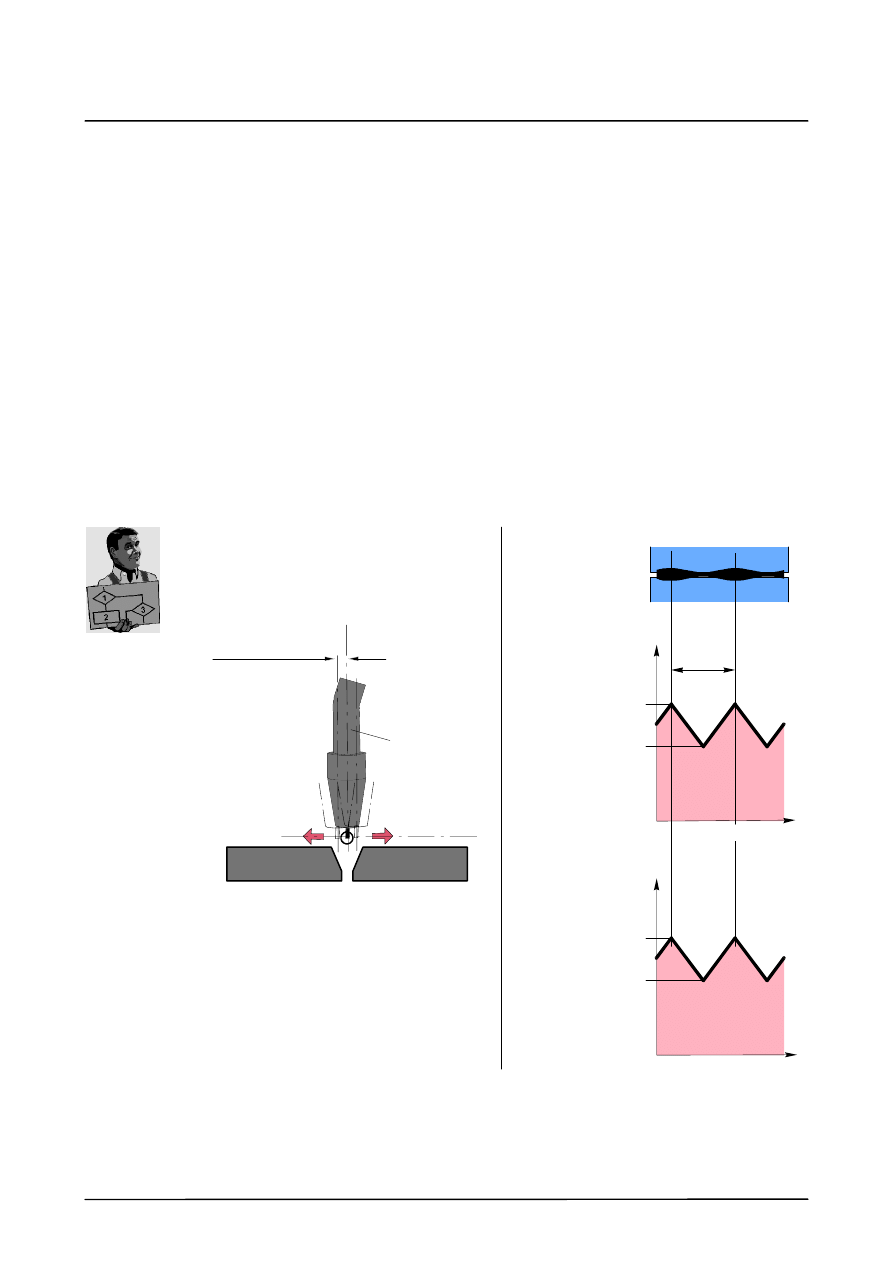
The following diagram illustrates mechanical and thermal weaving using the function
generator.
Weld direction
Weld direction
Max. feed
Min. feed
Wire feed
Length
(1 period)
Weld voltage
(volts)
Max. voltage
Min. voltage
Thermal weaving
Torch
Weave plane
Component
plane
Weave amplitude
Mechanical weaving
Taking the example of a weld
application
Function Generator
6 of 28
Funktionsgenerator KSS5.1 08.02.00 en
1.2
Functional description
1.2.1
Basic principle
The user defines a function which is evaluated accordingly by the system and processed
further. The input values of the function (distance, velocity, etc.), and also the further
processing of the results of the function (output to an analog channel, path correction, etc.),
can be selected and configured using variables.
1.2.2
Function definition
G
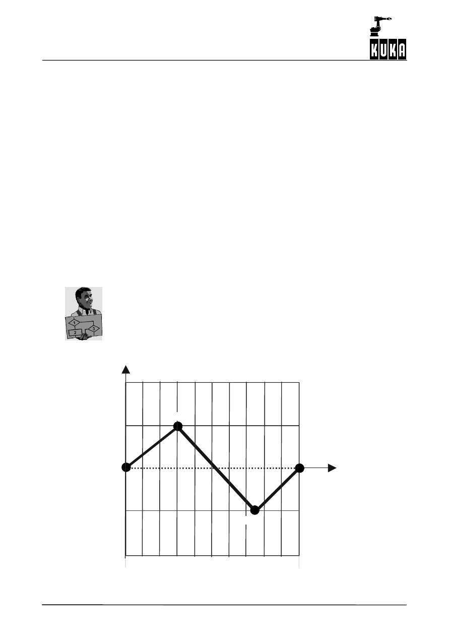
The required function y(x) is defined in the interval [0,1] as a polygon.
G
The polygon is defined unambiguously by entering function control points.
G
A maximum of 50 control points (x,y) is permissible. They must be selected as follows:
--
x is a real number from the interval [0,1]
--
y is a real number from the interval [--1,1]
For control points 1 to max. 50, the following must be observed: x1 < x2 < ...<xN
The first and last control points must be situated on the edge of the
definition range (x1=0, xN=1).
Example
The control points
(0,0),
(0.3,0.5),
(0.75,--0.5) and
(1,0)
result in the function illustrated below:
(0,0)
(0,1)
(0,--1)
Y
X
(1,--1)
(0.3,0.5)
(0.75,--0.5)
(1,1)
(1,0)
1
Characteristics, functional description (continued)
7 of 28
Funktionsgenerator KSS5.1 08.02.00 en
1.2.3
Correction direction
The correction direction is defined using a user--defined correction coordinate system
(tool--based technological system, $TECHSYS):
WORLD, BASE, ROBROOT, TCP and TTS
The following definitions apply here:
The correction coordinate system can be rotated using the variable $TECHANGLE:
A:
Rotation about the Z axis of the tool--based technological system
in the mathematically positive direction.
B:
Rotation about the Y’ axis of the tool--based technological system
in the mathematically positive direction.
C:
Rotation about the X’’ axis of the tool--based technological system
in the mathematically positive direction.
The definition can be made unambiguous by selecting an axis of the correction coordinate
system by means of a “GEOREF” variable.
Corrections are only possible in Cartesian space and not in axis space. This means
that the function generator is only available for CP motions (LIN, CIRC).
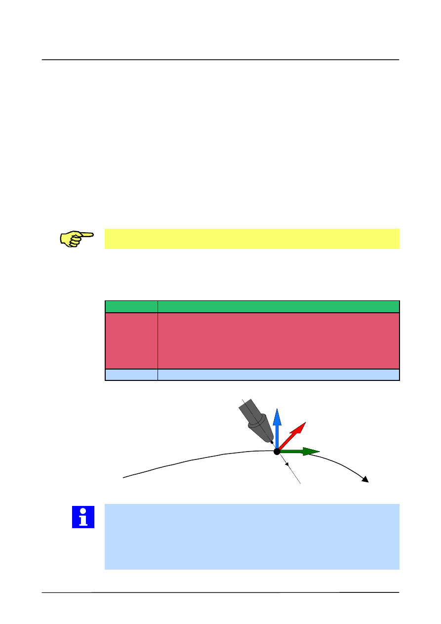
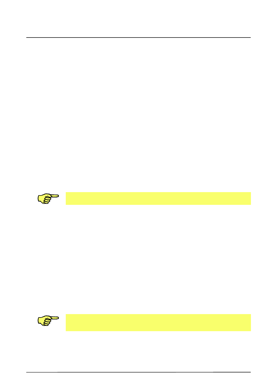
1.2.4
The correction coordinate system TTS
“TTS” stands for tool--based technological system. This tool--based moving frame is defined
as follows:
X axis
Unit vector in direction of path tangent.
Y axis
Unit vector in direction of vector product of path tangent and X axis of
tool coordinate system.
(Applying the right hand rule, the direction of the Y axis is that of the
middle finger if the thumb is pointing in the direction of the path tangent
and the index finger is pointing in the direction of the X axis of the tool
coordinate system.)
Z axis
Unit vector in direction of vector product of path tangent and Y axis.
Y axis (middle finger)
X axis (thumb)
Z axis
X
TOOL
axis
(index finger)
TTS
(tool--based technological system)
The correction coordinate system is calculated every time a CP motion is executed.
If the X axis of the tool coordinate system and the path tangent are parallel, the TTS cannot
be generated. The TTS is invalid in this case and results in the acknowledgement message
“TTS NOT EXISTING”
and dynamic braking when path correction is used.
In this case, a corresponding reorientation of the tool is required as well as reprogramming
of the motion.

Function Generator
8 of 28
Funktionsgenerator KSS5.1 08.02.00 en
1.3
Configuration
The maximum number of programmable function generators is selected in the robot--specific
machine data using the datum $TECH_MAX.
$TECH_MAX can be set to values between 3 and 6 with 3 being the default setting.
2
Programming, parameterization
9 of 28
Funktionsgenerator KSS5.1 08.02.00 en
2
Programming, parameterization
The function generator can be programmed using advance run and main run system
variables. Advance run variables are copied into the main run variables internally in the
system at the start of a motion or when changing block to an approximate positioning block.
The function generator, which is only active for CP motions, only evaluates the main run
variables.
For this reason, when controlling the function generator using advance run variables, a CP
motion block must then be executed so that the data are transferred to the main run data.
A so--called zero block is also valid in this case.
2.1
Structure variables
2.1.1
$TECH[i], $TECH_C[i], i=1,...,6
These are structure variables for defining the function and programming the evaluation of
the function.
$TECH[i]. MODE
The parameter “MODE” defines the type of evaluation of the function in the advance run. The
parameter can be changed in the program and is block--specific.
MODE
Effect
#OFF
The function is not evaluated.
#SINGLE
The definition range of the function is run through just once
when the function is evaluated.
#CYCLE
Cyclical evaluation of the function.
$TECH_C[i]. MODE
The parameter “MODE” defines the type of evaluation of the function in the main run. The
parameter can be changed using Trigger, Interrupt or the variable modification function and
the changes take effect immediately.
MODE
Effect
#OFF
The function is not evaluated.
#SINGLE
The definition range of the function is run through just once
when the function is evaluated.
#CYCLE
Cyclical evaluation of the function.
Function Generator
10 of 28
Funktionsgenerator KSS5.1 08.02.00 en
$TECH[i].CLASS
The parameter “CLASS” can be used to define the technology class in the advance run. The
parameter can be changed in the program and is block--specific.
CLASS
Effect
#PATH
The input variable for the function generator is the system
variable $DISTANCE. The unit for the scaling and offset
variables is [mm].
#VEL
The input variable for the function generator is the path
velocity ($VEL_ACT).
#SENSOR
The input variable for the function generator is the system
variable $TECHIN[i], i=1..6. Depending on the input values, a
corresponding position correction is carried out.
#CONVEYOR
The input variable for the function generator is the system
variable $TECHIN[i], i=1..6. Depending on the input values, a
corresponding tracking motion is executed by the robot.
#DATALINK
The input variable for the function generator is a correction
frame that is set by the sensor task. Depending on the input
values, a corresponding correction is carried out by the robot.
$TECH_C[i].CLASS
The parameter “CLASS” can be used to define the technology class in the main run. The
parameter cannot be changed.
CLASS
Effect
#PATH
The input variable for the function generator is the system
variable $DISTANCE. The unit for the scaling and offset
variables is [mm].
#VEL
The input variable for the function generator is the path
velocity ($VEL_ACT).
#SENSOR
The input variable for the function generator is the system
variable $TECHIN[i], i=1..6. Depending on the input values, a
corresponding position correction is carried out.
#CONVEYOR
The input variable for the function generator is the system
variable $TECHIN[i], i=1..6. Depending on the input values, a
corresponding tracking motion is executed by the robot.
#DATALINK
The input variable for the function generator is a correction
frame that is set by the sensor task. Depending on the input
values, a corresponding correction is carried out by the robot.
2
Programming, parameterization (continued)
11 of 28
Funktionsgenerator KSS5.1 08.02.00 en
$TECH[i].FCTCTRL
This is a function control structure for setting the scaling and offset parameters in the
advance run. The parameter can be changed in the program and is block--specific.
FCTCTRL
element
Effect
OFFSET_IN
Real value which, depending on the parameter CLASS, can be used
to offset the zero point of the definition range of the function.
OFFSET_OUT
Real value which, depending on the parameter CLASS, can be used
to offset the zero point of the value range of the function.
SCALE_IN
Real value which can be used to scale the definition range of the
function with reference to the parameter CLASS.
SCALE_OUT
Real value which can be used to scale the value range of the
function with reference to the parameter CLASS.
$TECH_C[i].FCTCTRL
Function control structure for setting the scaling and offset parameters in the main run. The
parameter can be changed using Trigger, Interrupt or the variable modification function and
the changes take effect immediately.
FCTCTRL
element
Effect
OFFSET_IN
Real value which, depending on the parameter CLASS, can be used
to offset the zero point of the definition range of the function.
OFFSET_OUT
Real value which, depending on the parameter CLASS, can be used
to offset the zero point of the value range of the function.
SCALE_IN
Real value which can be used to scale the definition range of the
function with reference to the parameter CLASS.
SCALE_OUT
Real value which can be used to scale the value range of the
function with reference to the parameter CLASS.
Function Generator
12 of 28
Funktionsgenerator KSS5.1 08.02.00 en
GEOREF
GEOREF
If the technology class SBC is selected, the variable GEOREF is
irrelevant.
NONE
This result of the function evaluation is only available
as the system variable $TECHVAL. With the
technology class SENSOR, this parameter has the
effect that no function evaluation is carried out.
X
In addition to the system variable, the calculated value
is also included in the calculation of the TCP in the
direction of the X axis of the TTS programmed using
$TECHSYS and $TECHANGLE, or in the direction of
the X BASE axis in the case of technology class
CONVEYOR.
Y
In addition to the system variable, the calculated value
is also included in the calculation of the TCP in the
direction of the Y axis of the TTS programmed using
$TECHSYS and $TECHANGLE, or in the direction of
the Y BASE axis in the case of technology class
CONVEYOR.
Z
In addition to the system variable, the calculated value
is also included in the calculation of the TCP in the
direction of the Z axis of the TTS programmed using
$TECHSYS and $TECHANGLE, or in the direction of
the Z BASE axis in the case of technology class
CONVEYOR.
For technology classes SENSOR and CONVEYOR, the following
parameters can also be programmed for GEOREF:
A
Significance for technology class SENSOR:
Rotation about the Z axis of the tool--based
technological system in the mathematically positive
direction.
Significance for technology class CONVEYOR:
Tracking motion about the Z axis of the BASE
coordinate system in the mathematically positive
direction.
B
Significance for technology class SENSOR:
Rotation about the Y axis of the tool--based
technological system in the mathematically positive
direction.
Significance for technology class CONVEYOR:
Tracking motion about the Y axis of the BASE
coordinate system in the mathematically positive
direction.
C
Significance for technology class SENSOR:
Rotation about the X axis of the tool--based
technological system in the mathematically positive
direction.
Significance for technology class CONVEYOR:
Tracking motion about the X axis of the BASE
coordinate system in the mathematically positive
direction.
2
Programming, parameterization (continued)
13 of 28
Funktionsgenerator KSS5.1 08.02.00 en
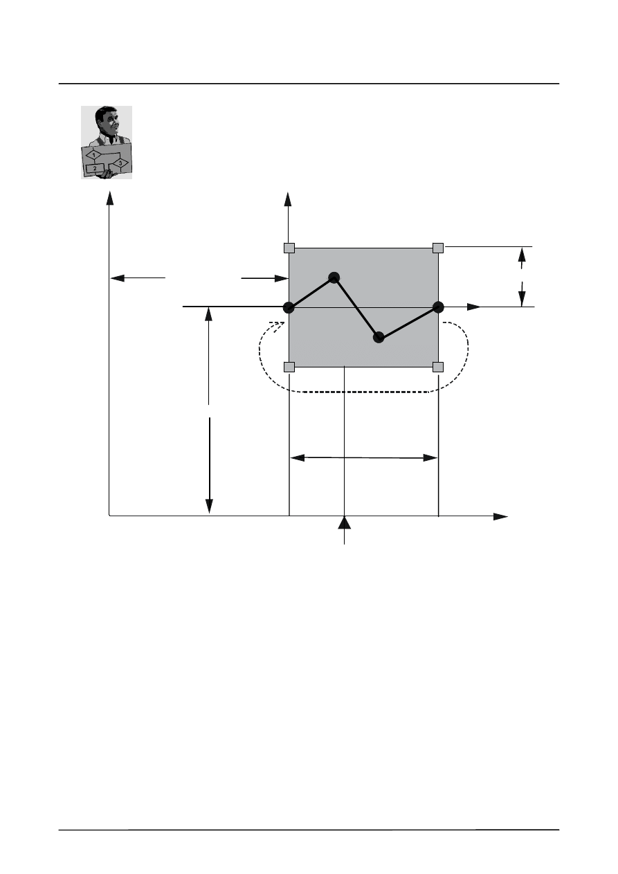
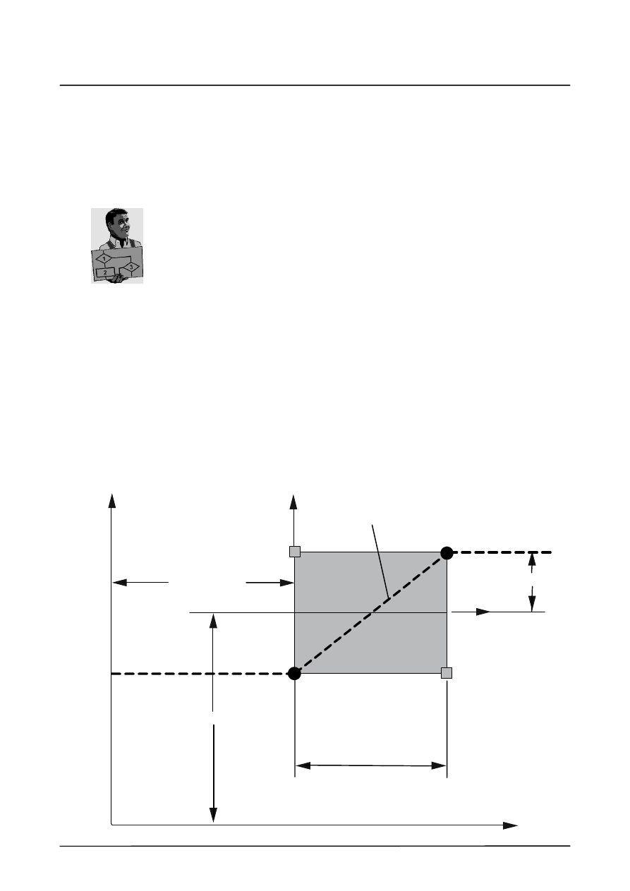
Example
$TECHVAL
(output variable)
OFFSET_IN
OFFSET_OUT
SCALE_IN
Technology mode
#CYCLE
e.g. length of arc
for #PATH
SCALE_OUT
(input variable)
$DISTANCE (CLASS = #PATH)
$VEL_ACT (CLASS = #VEL)
$TECHIN
(CLASS = #SENSOR,
CLASS = #CONVEYOR)
Correction frame
(CLASS = #DATALINK)
(0,--1)
(1,--1)
(0,0)
(1,0)
(0,1)
(1,1)
Y
X
Function Generator
14 of 28
Funktionsgenerator KSS5.1 08.02.00 en
$TECH[i].FCT
Defines the function in the advance run. It can be changed in the program and is
block--specific.
$TECH_C[i].FCT
Defines the function in the main run. It cannot be changed in the program.
FCT element
Effect
ORDER
Integer value specifying the degree of interpolation when the spline
is evaluated. The only degree of interpolation currently implemented
is 1.
CPNUM
Total number of valid control points in the following five control point
structures. The number of valid control points can be freely selected
between 2 and 50; no gaps are allowed between valid control
points.
CPS1
Control point list for control points 1 to 10
CPS2
Control point list for control points 11 to 20
CPS3
Control point list for control points 21 to 30
CPS4
Control point list for control points 31 to 40
CPS5
Control point list for control points 41 to 50
2.1.2
$TECHIN[i], i = 1,...,6
The system variable $TECHIN forms the interface between the cyclical analog and digital
inputs of the KR Cx and the function generator. The contents of this variable serve as the
input variable for the function generator.
The variable has the data type REAL and cannot be modified in the program.
2.1.3
$TECHPAR[i, j], i=1,...,6 , j=1,...,10
This is used for parameterization or output of the function generator (analog sensors,
conveyor tracking, etc.) in the advance run. Ten input parameters and ten output parameters
are available to each function generator (i). If a parameter is used to output function
generator states, the parameter value that is current in the interpolation cycle can be found
in the main run variable.
The data type is REAL. The variable can be modified in the program and is block--specific.
2.1.4
$TECHPAR_C[i, j], i = 1,...,6 , j=1,...,10
This is used for parameterization or output of the function generator (analog sensors,
conveyor tracking, etc.) in the main run. Ten input parameters and ten output parameters are
available to each function generator (i). If a parameter is used to output function generator
states, the parameter value that is current in the interpolation cycle can be found in the main
run variable.
The data type is REAL. The variable can be modified using Trigger, Interrupt or the variable
modification function. The changes take effect immediately.

2
Programming, parameterization (continued)
15 of 28
Funktionsgenerator KSS5.1 08.02.00 en
2.1.5
$TECHVAL[i], i = 1,...,6
This is an output variable of the function generator. SCALE_OUT and OFFSET_OUT are
included in the calculations.
This variable has the data type REAL and cannot be modified during program execution.
2.1.6
$TECHSYS
Used for programming the TTS in the advance run. The coordinate systems #WORLD,
#BASE, #ROBROOT, #TCP and #TTS can be programmed. If GEOREF < > (is not equal
to) #NONE, then the calculated function values refer to the programmed coordinate system.
This variable can be modified in the program and is block--specific.
2.1.7
$TECHSYS_C
This variable is used for programming the TTS in the main run. The coordinate systems
#WORLD, #BASE, #ROBROOT, #TCP and #TTS can be programmed.
If GEOREF < > (is not equal to) #NONE, then the calculated function values refer to the
programmed coordinate system.
This variable can be modified using Trigger, Interrupt or the variable modification function
and the changes take effect immediately.
2.1.8
$TECHANGLE
Used for programming the rotation of the TTS in the advance run.
The rotation is specified in RPY angles.
This variable can be modified in the program and is block--specific.
2.1.9
$TECHANGLE_C
Used for programming the rotation of the TTS in the main run. The rotation is specified in
RPY angles.
The variable can be modified using Trigger, Interrupt or the variable modification function and
the changes take effect immediately.
2.1.10 $TSYS
For each interpolation cycle, this system variable contains the current TTS – insofar as there
is one available – with reference to the base coordinate system.
This variable is of type FRAME and cannot be modified.
2.1.11 $DISTANCE
This variable allows path--related function evaluation. During program execution, it
represents the current arc length of a Cartesian motion in millimeters.
$DISTANCE is set to zero at the start of an individual CP block or at the start of the CP motion
in a PTP/CP approximate positioning motion.
This variable is of type REAL and cannot be modified.

Function Generator
16 of 28
Funktionsgenerator KSS5.1 08.02.00 en
2
Programming, parameterization (continued)
17 of 28
Funktionsgenerator KSS5.1 08.02.00 en
2.2
Analog sensors
2.2.1
Interface
The system variables $TECHIN[i] (i = 1 .. 6) form the interface between the sensor inputs
and the function generator.
These variables are written to cyclically using the following statements and serve as the input
variable for the function generator.
Analog input:
SIGNAL CORRECTION $ANIN[1]
ANIN ON $TECHIN[2] = FACTOR * CORRECTION + OFFSET
Digital input:
Entry in “$MACHINE.DAT”
SIGNAL $DIGIN1 $IN[20] TO $IN[27]
DECL DIGINCODE $DIGIN1CODE=#UNSIGNED
DIGIN ON $TECHIN[3] = FACTOR * $DIGIN1 + OFFSET
2.2.2
Parameterization
Elements of the array variable $TECHPAR[i,j] are used for parameterization and for
outputting function generator states.
Technology class SENSOR ($TECH[i].CLASS = #SENSOR) causes the function generator
to use the variable $TECHIN[i] and thus the sensor signal as the input variable.
For function generator class #SENSOR, the function definition describes a controller
characteristic as illustrated in the following diagram.
Correction velocity
[mm/s] or [degrees/s]
OFFSET_IN
OFFSET_OUT
SCALE_IN
Technology mode
#CYCLE
$TECHIN
SCALE_OUT
(0,--1)
(1,--1)
(0,0)
(1,0)
(0,1)
(1,1)
Y
X
Controller characteristic
Function Generator
18 of 28
Funktionsgenerator KSS5.1 08.02.00 en
If the definition range “SCALE_IN” is exceeded, the corresponding limit value is
maintained.
For function generator class “#SENSOR”, the function generator calculates a correction
velocity (mm/s or degrees/s) from the input values. This correction velocity is used to
calculate a correction value (mm, degrees) which is added up in every interpolation cycle
(sensor correction, initial value 0.0).
With corresponding parameterization, the correction velocity is 0 (zero) and the sensor
correction value remains constant in the balanced state.
The correction velocity is smoothed before the correction value is calculated in order to avoid
abrupt corrections. This smoothing can be set using $TECHPAR[i,1].
If the filter $TECHPAR[i,1] is set to less than the duration of an interpolation cycle, the
unfiltered velocity value is used for calculating the correction.
2.2.3
Correction direction
The correction direction is defined, as is usual for the function generator, by means of the
variables
$TECHSYS, $TECHANGLE and GEOREF.
Using the components
#A, #B, and #C
of the ENUM variable GEOREF, it is also possible to carry out an orientation correction to
the corresponding angles.
G
#A:
Rotation of the X axis of the tool about the Z axis of the tool--based technological
system in the mathematically positive direction.
G
#B:
Rotation of the X axis of the tool about the Y axis of the tool--based technological
system in the mathematically positive direction.
G
#C:
Rotation of the X axis of the tool about the X axis of the tool--based technological
system in the mathematically positive direction.
Since the tool--based technological system changes its position when following a contour,
the correction increase in the direction/orientation defined by GEOREF and calculated in the
interpolation cycle is converted to the corresponding BASE components (dx, dy, dz or da,
db, dc).
Z BASE
Y BASE
X BASE
GEOREF
ds
dz
dx
dy
X TSYS
Y TSYS
Z TSYS
ds = correction velocity * t_ipo
2
Programming, parameterization (continued)
19 of 28
Funktionsgenerator KSS5.1 08.02.00 en
The correction increase in the BASE components is added up (dX, dY, dZ or dA, dB, dC),
included in the calculation of the TCP and can be accessed by the user via the TECHPAR
variables.
TECHPAR_C[i, 3] : Correction value in X BASE (dX)
TECHPAR_C[i, 4] : Correction value in Y BASE (dY)
TECHPAR_C[i, 5] : Correction value in Z BASE (dZ)
TECHPAR_C[i, 6] : Correction value in A BASE (dA)
TECHPAR_C[i, 7] : Correction value in B BASE (dB)
TECHPAR_C[i, 8] : Correction value in C BASE (dC)
In the case of a TCP correction (GEOREF = #X, #Y or #Z), the value of the correction vector
in BASE (unit = mm) is written to the output variable of the function generator ($TECHVAL[i])
and can then be used, with the aid of two interrupt declarations, for monitoring the sensor
correction.
INTERRUPT DECL 1 WHEN $TECHVAL[1] > 20.0 DO UPPER_LIMIT()
INTERRUPT DECL 2 WHEN $TECHVAL[1] < --20.0 DO LOWER_LIMIT()
In the case of an orientation correction (GEOREF = #A, #B or #C), the value is calculated
using the correction angle in
BASE (dA, dB, dC)
and transferred to TECHVAL[i].
$TECHVAL[i] = SQRT(dA2 + dB2 + dC2)
All correction values that are made available to the user are interpolator command values
and are not filtered, i.e. there is no reference to actual values.
2.2.4
Changing technology mode, correction variable
Switching the technology mode from #CYCLE to #SINGLE has the effect that the input
variable $TECHIN[i] is no longer evaluated. The correction velocity is set to zero internally
in the system thus keeping the established sensor correction vector constant.
When an exact positioning point is reached, the correction variable is retained and is used
for the subsequent CP motion. This applies also for the transition to the following block when
a CP approximation contour is executed.
Block selection, program reset and interrupt commands followed by the RESUME statement
cause the start values of the motion block to be initialized and the correction value is lost.
The sensor offset is set to 0 in the function generator.
No sensor offset is permissible in the case of a PTP motion. If there is a correction value
present, the acknowledgement message
“DEVIATION IN THE START POINT”
is generated.
The instruction $TECH[i].MODE=#OFF triggers an advance run stop, deactivates the
functionality of the sensors, sets the sensor offset to 0 and continues the motion from the
current point in space.
Function Generator
20 of 28
Funktionsgenerator KSS5.1 08.02.00 en
2.3
Conveyor synchronization
The system variables $TECHIN[i] (i = 1 .. 6) form the interface between the sensor inputs
and the conveyor functionality.
Data are written to these variables cyclically using the following statements:
Analog input:
SIGNAL CONVEYORVEL $ANIN[1]
ANIN ON $TECHIN[2] = FACTOR * CONVEYORVEL + OFFSET
Digital input:
Entry in “$MACHINE.DAT”
SIGNAL $DIGIN1 $IN[20] TO $IN[28]
DECL DIGINCODE $DIGIN1CODE=#UNSIGNED
DIGIN ON $TECHIN[3] = FACTOR * $DIGIN1 + OFFSET
Elements of the array variable $TECHPAR[i,j] are used for parameterization and for
outputting function generator states as described below.
Two conveyor modes are possible. The robot tracks the conveyor in the case of translational
or rotational motions of the part to be processed, e.g. with a conveyor belt or turntable.
The coordinate system in which tracking motions are possible is defined by means of the first
six TECHPAR variables of the next function generator.
If, for example, function generator 1 has been configured for the conveyor function,
$TECHPAR[2,1] to $TECHPAR[2,6] contain the tracking coordinate system (X, Y, Z, A, B,
C) with reference to $WORLD.
Function generator 2 should not be used for any other purpose in this case.
The TECH variable “GEOREF” defines the correction direction in this coordinate system.
The parameters
#X, #Y and #Z
define a translational correction in the corresponding direction.
For rotational tracking, the parameters
#A, #B and #C
of the “GEOREF” variable are used:
#A --> about Z, #B --> about Y, #C --> about X.
In the case of translational conveyor mode, it is of vital importance to ensure that the
tracking direction corresponds to the direction of motion of the conveyor belt.
In the case of rotational motions of the part, the correction axis must be located at the center
of rotation, for example:
GEOREF=#A
where the Z axis of the conveyor (Z Conv.) is the rotational axis and the direction of rotation
is mathematically positive.
2
Programming, parameterization (continued)
21 of 28
Funktionsgenerator KSS5.1 08.02.00 en
If the following is selected
GEOREF=#NONE
the tracking distance is calculated and is available to the user via the variable
$TECHVAL[i]
The robot does not carry out tracking, however.
The conveyor function is defined by means of the technology class
CONVEYOR ( $TECH[i].CLASS = #CONVEYOR)
and activated with technology mode “CYCLE”.
The parameter $TECHPAR[i,8] defines whether the variable $TECHIN[i] refers to a velocity
value or a distance.
$TECHPAR[i,8]=0 ----> $TECHIN[i] refers to a velocity
$TECHPAR[i,8]=1 ----> $TECHIN[i] refers to a distance
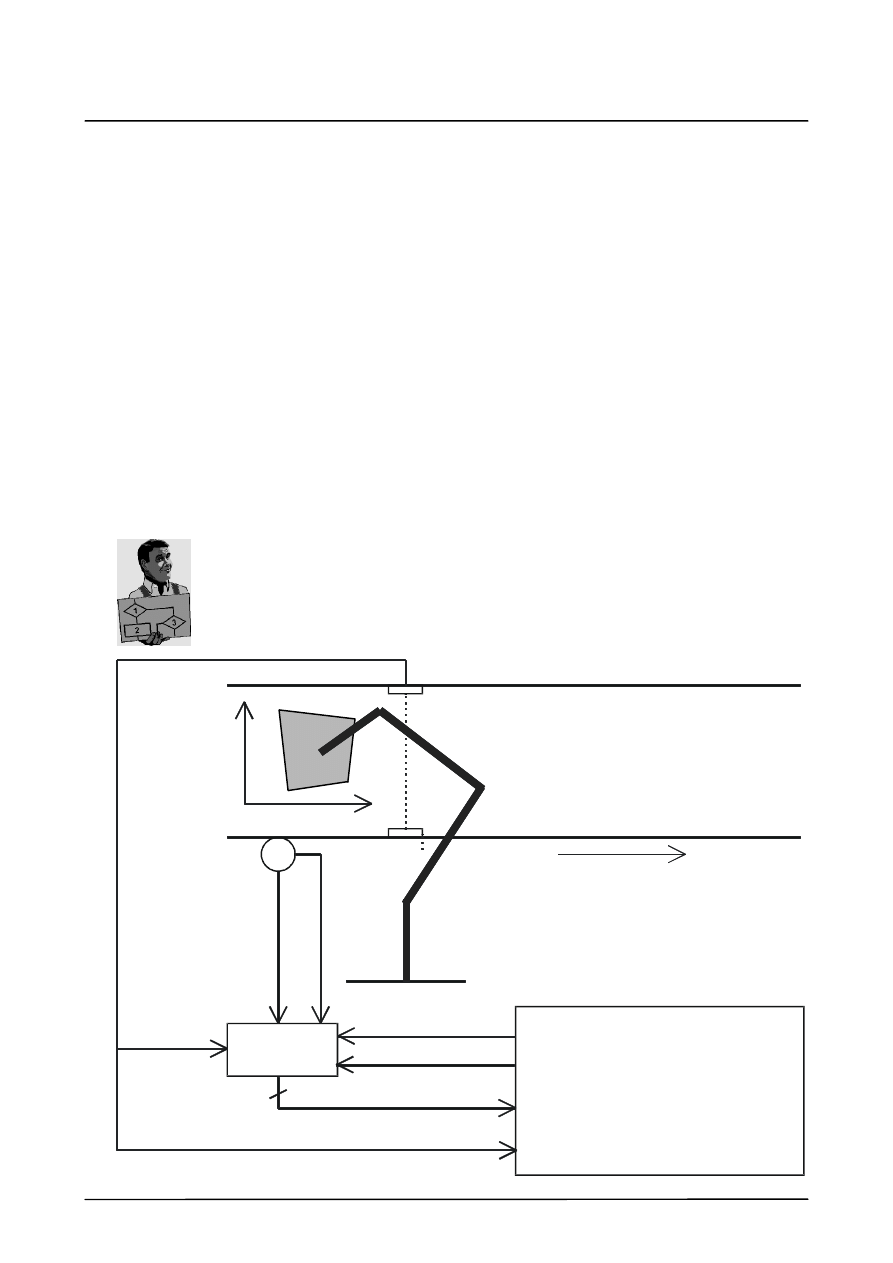
In the case of a conveyor synchronization with an “absolute” position sensing system,
$TECHPAR[i,8] must be set to 1.
Example:
The synchronization switch enables the counting mode.
At the end of the tracking operation, a digital output in the KRC ensures that the counter
is set to 0 and that the enabling of the counting mode is withdrawn.
The 16--bit values are scaled to [mm] using the FACTOR in the
DIGIN statement.
KR C2
Direction of motion
Conveyor
Synchronization switch
Incremental
encoder
Pulse
Direction
of
rotation
Counter
Start counter
(enable)
16 bits
DIGIN ON
$TECHIN[i]=FACTOR*$DIGIN1+OFFSET
Start signal (digital input)
16 digital inputs
Z Conv.
P1
P2
P3
P4
Robot
Reset counter
(digital output)
Strobe (digital output)
X Conv.
Function Generator
22 of 28
Funktionsgenerator KSS5.1 08.02.00 en
If the parameter $TECHPAR[i,8] is set to 0, the tracking distance is calculated on the basis
of the conveyor velocity which is assigned cyclically to $TECHIN[i] by means of an ANIN or
DIGIN statement.
Make sure that $TECHIN[i] contains the conveyor velocity value in mm/s or degrees/s.
This is done by means of the factor in the ANIN/DIGIN statement.
The system variable $TECHVAL[i] contains the absolute tracking distance in mm or degrees.
This variable can be used to monitor the maximum permissible tracking distance, e.g.
INTERRUPT DECL 1 WHEN $TECHVAL[i] > 2000.0 DO STOP_TRACK()
The robot tracking motion is started by means of a synchronization signal which the conveyor
system sends to the robot controller when the part enters the robot’s processing area.
This synchronization input (user input) is transferred to the system via the variable
$TECHPAR[i,7]. The program interpreter is stopped by means of a
“WAIT FOR $TECHVAL[i]>0.05” statement
once the conveyor synchronization has been activated.
The conveyor functionality is activated as soon as the technology mode is switched to
CYCLE and the technology class CONVEYOR is selected.
Once the robot has detected the synchronization signal it leaves its starting position and
starts tracking and processing. For this kind of start from the rest position with the conveyor
already running (so--called “flying start”), special precautions (smoothing) must be taken in
order to ensure a “smooth”, but nonetheless sufficiently rapid, synchronization of the robot
motion with the conveyor motion.
The corresponding parameters are set using elements of $TECHPAR[i,j]:
G
“Distance gain” $TECHPAR[i,1] in [1/s],
G
“Velocity gain” $TECHPAR[i,2] in [1/s].
The following error between the conveyor and the robot caused by the smoothing and the
system run times can be compensated for by the user by means of
$TECHPAR[i,3] (rate time in s).
As the function generator (interpolator) is not called during pauses between motions, no
exact positioning motion should be programmed at any point in the tracking operation.
A programmed point can be reached exactly by setting the approximation radius to 0 (zero).
If it is necessary for there to be pauses between robot motions, this can be achieved by
setting the override to zero at the corresponding point in the program (TRIGGER in
approximation zero block).
The instruction $TECH[i].MODE=#OFF triggers an advance run stop, deactivates the
conveyor functionality, sets the tracking distance to 0 and continues the motion from the
current point in space.

2
Programming, parameterization (continued)
23 of 28
Funktionsgenerator KSS5.1 08.02.00 en
2.4
Complex sensors
Using an add--on controller task (sensor task), it is possible to couple an “intelligent” sensor
to the controller and correct the robot motion in Cartesian space ($TECH[i].CLASS =
#DATALINK).

Function Generator
24 of 28
Funktionsgenerator KSS5.1 08.02.00 en

3
Application examples
25 of 28
Funktionsgenerator KSS5.1 08.02.00 en
3
Application examples
3.1
Weaving
Example
DECL
TECH
WEAVE1, WEAVE2
; Declare variables of type TECH
WEAVE1.MODE
= #CYCLE
; Cartesian weaving is a cyclical
; function.
WEAVE1.FCTCTRL.SCALE_IN
= 2
; Wavelength of the weave oscillation is
; 2 mm.
WEAVE1.FCTCTRL.OFFSET_IN = 0
; Start of deflection is start of CP path.
WEAVE1.FCTCTRL.SCALE_OUT = 3
; Weave amplitude is 3 mm.
WEAVE1.FCTCTRL.OFFSET_OUT = 0
; Focus of the weave oscillation is
; on the path:
; If amplitude = 0, path is followed without
; weaving.
WEAVE1.CLASS = #PATH
; Argument of the weave pattern is the
; arc length, i.e. SCALE_IN the
; wavelength.
WEAVE1.FCTCTRL.GEOREF = #Y
; Direction of the weave deflection in the Y
; direction in the TTS
WEAVE1.FCT.ORDER = 1
; Create weave pattern from polygon using
; pairs of values in the function table.
TECHANGLE.C = 10
; Rotate TTS
; User--defined WEAVE1 is ready for assignment to the technology structure $TECH[1]
; Prepare FCTCTRL section of the structure WEAVE2 for structure
; assignment using TRIGGER command!
WEAVE2.MODE
= #CYCLE
; Cartesian weaving is a cyclical
; function.
WEAVE2.FCTCTRL.SCALE_IN
= 4
; Wavelength of the weave oscillation is
; 4 mm.
WEAVE2.FCTCTRL.OFFSET_IN = 0
; Start of deflection at start of CP path.
WEAVE2.FCTCTRL.SCALE_OUT = 3
; Weave amplitude is 3 mm.
WEAVE2.FCTCTRL.OFFSET_OUT = 0
; Focus of the weave oscillation is
; the path.
$TECH[1] = WEAVE1
; Weaving from next CP block onwards.
PTP X1
; PTP blocks always without weaving.
LIN L1
; Weaving with values of the structure
; WEAVE1.
$TECH[1].FCTCTRL.GEOREF = #Z
LIN L2 C_DIS
; Weaving in the Z direction, i.e. perpendicular
; to the plane of the panels to be welded,
; from the start of this block onwards.
TRIGGER WHEN DISTANCE=1 DELAY=0 DO
$TECH_C[1].FCTCTRL = WEAVE2.FCTCTRL
LIN L3 C_DIS
; From the center of the intermediate
; block of the approximate positioning,
; weaving with new wavelength 4 mm.
LIN L4
$TECH[1].MODE = #OFF
LIN L5
; This motion block without weaving

Function Generator
26 of 28
Funktionsgenerator KSS5.1 08.02.00 en
3.2
Analog sensor
Example
Using a distance sensor, a correction is to be made in the Z direction of the TTS.
Calibration is carried out using the offset variables. The maximum value for the correction
vector should be +/-- 20 mm.
The analog input delivers a voltage between --10 V and +10 V; this should be adjusted to
0 V.
FACTOR = 0.1
OFFSET = 1.0
; Sensor at analog input 2
SIGNAL CORRECTION $ANIN[2]
; Monitor sensor correction value
INTERRUPT DECL 1 WHEN $TECHVAL[1] > 20.0 DO UPPER_LIMIT()
INTERRUPT DECL 2 WHEN $TECHVAL[1] < -20.0 DO LOWER_LIMIT()
; Activate cyclical reading of the analog input and
; scaling of $TECHIN[1] to 0.0 - 2.0
ANIN ON $TECHIN[1] = FACTOR * CORRECTION + OFFSET
; Define correction direction
$TECHSYS = #TTS
$TECH[1].FCTCTRL.GEOREF = #Z
; Correction in Z direction
; Sensor correction using the function generator
$TECH[1].CLASS = #SENSOR
$TECH[1].FCTCTRL.SCALE_IN = 2.0
;
Definition of control parameters
$TECH[1].FCTCTRL.OFFSET_IN = 0.0 ;
”
$TECH[1].FCTCTRL.SCALE_OUT = 20.0;
”
$TECH[1].FCTCTRL.OFFSET_OUT = 0.0;
”
$TECH[1].FCT.ORDER = 1
;
”
$TECH[1].FCT.CPNUM = 3
;
”
$TECH[1].FCT.CPS1.X1 = 0.0
;
”
$TECH[1].FCT.CPS1.Y1 = -1.0
;
”
$TECH[1].FCT.CPS1.X2 = 0.5
;
”
$TECH[1].FCT.CPS1.Y2 = 0.0
;
”
$TECH[1].FCT.CPS1.X3 = 1.0
;
”
$TECH[1].FCT.CPS1.Y3 = 1.0
;
”
$TECHPAR[1,1] = 0.056
;
Smoothing constant in s
PTP BEFORE_PART
INTERRUPT ON 1
INTERRUPT ON 2
; Activate sensor correction
TECH[1].MODE = #CYCLE
LIN P1 C_DIS
LIN P2 C_DIS
LIN P3
; Deactivate sensor correction
TECH[1].MODE = #OFF
LIN_REL {X 0.0}
; Zero block for accepting advance run data
; in the main run data --> Deactivation of
; the function generator
; Deactivate cyclical analog input
ANIN OFF CORRECTION
3
Application examples (continued)
27 of 28
Funktionsgenerator KSS5.1 08.02.00 en
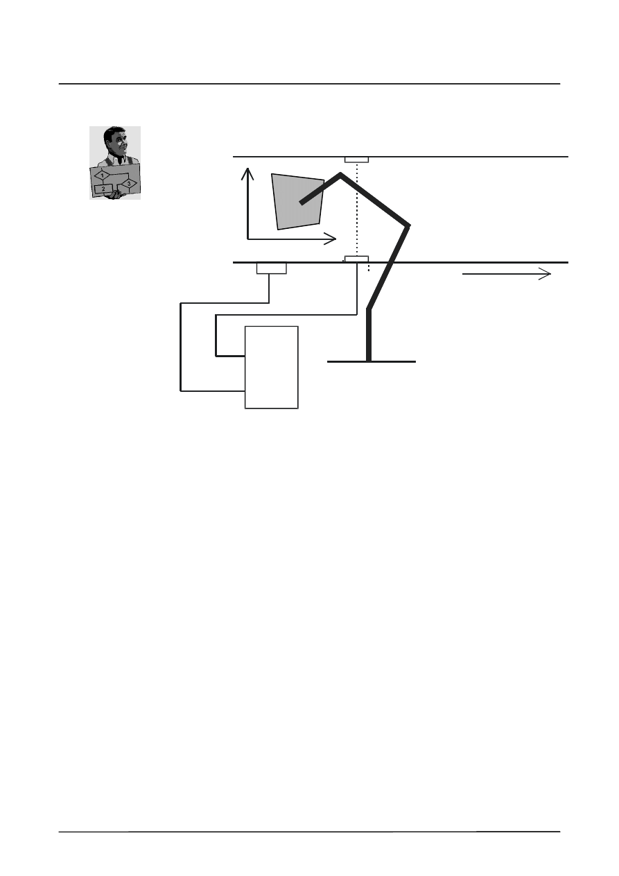
3.3
Conveyor synchronization
Example
Conveyor
Direction of motion
Robot
Velocity measuring system
KR C1
Z Conv.
P1
P2
P3
P4
Synchronization switch
X Conv.
Analog input
Digital
input
A workpiece on a conveyor belt is moved past a robot. The velocity measuring system
delivers a voltage of 10.0 V in the case of a maximum conveyor velocity of 0.08 m/s.
The voltage range of the analog input is 0 V to 10.0 V.
FACTOR = 80
OFFSET = 0.0
; Number of the user input to which the synchronization switch is attached
SYNCH_NO = 5
; Velocity measuring system at analog input 2
SIGNAL CONVEYORVEL $ANIN[2]
; Monitor tracking distance
INTERRUPT DECL 1 WHEN $TECHVAL[1] > 2000.0 DO STOP_TRACK()
; Define conveyor coordinate system relative to WORLD, Z axis points in
; direction of motion of the conveyor
$TECHPAR[2,1] = ...
; X Conv.
$TECHPAR[2,2] = ...
; Y Conv.
$TECHPAR[2,3] = ...
; Z Conv.
$TECHPAR[2,4] = ...
; A Conv.
$TECHPAR[2,5] = ...
; B Conv.
$TECHPAR[2,6] = ...
; C Conv.
; Activate cyclical reading of the analog input
ANIN ON $TECHIN[1] = FACTOR * CONVEYORVEL + OFFSET

Function Generator
28 of 28
Funktionsgenerator KSS5.1 08.02.00 en
; Conveyor synchronization using the function generator
$TECH[1].CLASS = #CONVEYOR
; Tracking direction is the Z axis of the conveyor coordinate system
$TECH[1].FCTCTRL.GEOREF = #Z
; Define control parameters
$TECHPAR[1,1] = 0.6
; “Distance gain” in 1/s
$TECHPAR[1,2] = 0.7
; “Velocity gain” in 1/s
$TECHPAR[1,3] = 0.084
; Rate time in s
$TECHPAR[1,7] = SYNCH_NO
; Synchronization input
$TECHPAR[1,8] = 0
; $TECHIN[i] corresponds to a
; velocity value
; (measuring sensor is a tachometer)
PTP WAIT_POS
INTERRUPT ON 1
; Activate conveyor synchronization
TECH[1].MODE = #CYCLE
LIN_REL {X 0.0}
; Zero block for accepting advance run data
; in the main run data --> Activation of
; conveyor functionality
; Wait for the synchronization signal
WAIT FOR $TECHVAL[1]>0.05
; Wait until the system has
; detected the synchronization signal
; --> $TECHVAL “grows”
; Process workpiece
LIN P1 C_DIS
LIN P2 C_DIS
LIN P3 C_DIS
LIN P4 C_DIS
LIN AWAY_FROM_BELT
; Deactivate robot tracking
TECH[1].MODE = #OFF
LIN_REL {X 0.0}
; Zero block for accepting advance run data
; in the main run data --> Deactivation of
; the function generator
; Deactivate cyclical analog input
ANIN OFF CONVEYORVEL
1

Index
Index -- i
Symbols
#CYCLE, 19
#SENSOR, 17, 18
#SINGLE, 19
$ANIN[1], 17, 20
$DIGIN1, 17
$DISTANCE, 15
$MACHINE.DAT, 17, 20
$TECH[i]. MODE, 9
$TECH[i].CLASS, 17
$TECH[i].CLASS , 10
$TECH[i].FCT, 14
$TECH[i].FCTCTRL , 11
$TECH[i].MODE, 19, 22
$TECH[i], $TECH_C[i], 9
$TECH_C[i]. MODE, 9
$TECH_C[i].CLASS , 10
$TECH_C[i].FCT, 14
$TECH_C[i].FCTCTRL, 11
$TECH_MAX, 8
$TECHANGLE, 7, 15
$TECHANGLE_C, 15
$TECHIN[i], 14, 17, 19, 20
$TECHPAR, 17, 20, 22
$TECHPAR[i, j], 14
$TECHPAR[i,1, 18
$TECHPAR[i,1], 18
$TECHPAR[i,j], 20
$TECHPAR_C[i, j], 14
$TECHSYS, 7, 15, 18
$TECHSYS_C, 15
$TECHVAL[i], 15, 19, 21
$TSYS, 15
A
Analog sensors, 17
B
BASE, 19
C
Configuration, 8
Control points, 6
Conveyor synchronization, 20
Correction coordinate system, 7
Correction coordinate system TTS, 7
Correction direction, 7
Correction value, 18
Correction velocity, 18
CYCLE, 21
D
DIGIN statement, 21
F
Function definition, 6
Functional description, 6
G
GEOREF, 7, 18, 20
M
Mechanical weaving, 5
O
OFFSET_OUT, 15
P
Parameterization, 9
Programming, 9
R
Reaching a programmed point, 22
RESUME, 19
S
SCALE_OUT, 15
Sensor correction value, 18
Sensor offset, 19
SIGNAL $DIGIN1, 17
SIGNAL CORRECTION, 17
Structure variables, 9

Index
Index -- ii
T
TCP correction, 19
TECHPAR variables, 20
TECHVAL[i], 19
Thermal weaving, 5
Tool--based technological system, 7
Tool--based technological system (TTS), 7, 15
TTS, 7
W
WAIT FOR $TECHVAL[i], 22
Document Outline
- Characteristics, functional description
- Programming, parameterization
- Application examples
Wyszukiwarka
Podobne podstrony:
MEDC17 Special Function Manual
MEDC17 Special Function Manual
XRC Interrupt function manual
PS4 Suscosoft S40 Function Block Reference Manual h1365g
L 3 Complex functions and Polynomials
3 ABAP 4 6 Basic Functions
PANsound manual
als manual RZ5IUSXZX237ENPGWFIN Nieznany
hplj 5p 6p service manual vhnlwmi5rxab6ao6bivsrdhllvztpnnomgxi2ma vhnlwmi5rxab6ao6bivsrdhllvztpnnomg
BSAVA Manual of Rabbit Surgery Dentistry and Imaging
Okidata Okipage 14e Parts Manual
Bmw 01 94 Business Mid Radio Owners Manual
Manual Acer TravelMate 2430 US EN
manual mechanika 2 2 id 279133 Nieznany
4 Steyr Operation and Maintenance Manual 8th edition Feb 08
Oberheim Prommer Service Manual
więcej podobnych podstron