
Initial Print Date: 01/09
Table of Contents
Subject
Page
System Circuit Diagram - Power Windows . . . . . . . . . . . . . . . . . . . . . . . . .6
Examples of the Signal Path . . . . . . . . . . . . . . . . . . . . . . . . . . . . . . . . . .7
Driver’s Door Switch Cluster . . . . . . . . . . . . . . . . . . . . . . . . . . . . . . . . . .7
Power Window Switch, Front Passenger’s Door . . . . . . . . . . . . . . . . .7
Power Window Switch, Rear Doors . . . . . . . . . . . . . . . . . . . . . . . . . . . .7
Opening and Closing . . . . . . . . . . . . . . . . . . . . . . . . . . . . . . . . . . . . . . . .8
Opening and Closing with Toll Function . . . . . . . . . . . . . . . . . . . . . . . .8
Auto-remote Opening and Closing . . . . . . . . . . . . . . . . . . . . . . . . . . . .10
Auto-remote opening with identification transmitter . . . . . . . . .10
Auto-remote closing with identification transmitter . . . . . . . . . .10
Auto-remote opening and closing via the driver’s
Auto-remote closing with Comfort Access . . . . . . . . . . . . . . . . .10
Indirect Pressure-sensitive Finger Guard . . . . . . . . . . . . . . . . . . . . . . .11
Load shut-down, Terminal 50 . . . . . . . . . . . . . . . . . . . . . . . . . . . . . . . .12
Overheating Protection of Power Window Motors . . . . . . . . . . . . . .12
System Circuit Diagram - Roller Sun Blind . . . . . . . . . . . . . . . . . . . . . . . .16
Overview of Functional Principle . . . . . . . . . . . . . . . . . . . . . . . . . . . . . . . .18
Pressure-sensitive Finger Guard for Side Window . . . . . . . . . . . . . .18
Roller Sun Blind on Rear Window . . . . . . . . . . . . . . . . . . . . . . . . . . . .18
Position of roller sun blinds unknown . . . . . . . . . . . . . . . . . . . . . .19
Blocking detection . . . . . . . . . . . . . . . . . . . . . . . . . . . . . . . . . . . . . .19
Child safety lock . . . . . . . . . . . . . . . . . . . . . . . . . . . . . . . . . . . . . . . .20
Roller sun blind switches . . . . . . . . . . . . . . . . . . . . . . . . . . . . . . . . .20
Driver’s door switch cluster . . . . . . . . . . . . . . . . . . . . . . . . . . . . . . .23
Signal evaluation of the power window switches . . . . . . . . . . . .24
F01 Power Windows
Revision Date:

Subject
Page
Car Access System 4 . . . . . . . . . . . . . . . . . . . . . . . . . . . . . . . . . . . .24
Footwell module . . . . . . . . . . . . . . . . . . . . . . . . . . . . . . . . . . . . . . . .24
Junction box electronics . . . . . . . . . . . . . . . . . . . . . . . . . . . . . . . . .24
Identification Transmitter . . . . . . . . . . . . . . . . . . . . . . . . . . . . . . . . . . . .24
Power Window Motors . . . . . . . . . . . . . . . . . . . . . . . . . . . . . . . . . . . . .24
Initialization of Power Windows . . . . . . . . . . . . . . . . . . . . . . . . . . . . . . .25
Initialization via the power window switches . . . . . . . . . . . . . . . .25
Initialization via the BMW diagnosis system . . . . . . . . . . . . . . . . .25

Subject
Page
BLANK
PAGE

4
F01 Power Windows
Power Windows
Model: F01/F02
Production: From Start of Production
After completion of this module you will be able to:
• Understand the operation of the power windows on the F01/F02
• Locate and identify power system components
5
F01 Power Windows
System Overview
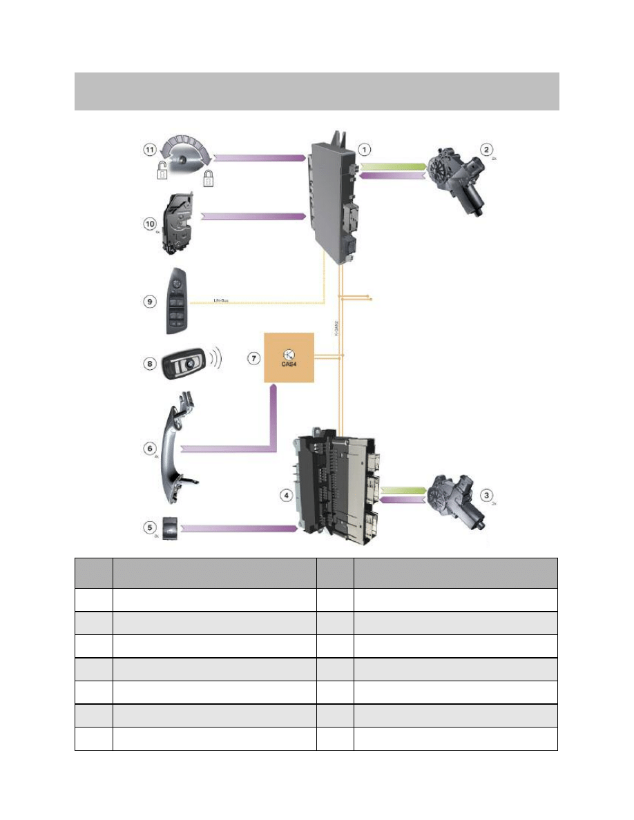
Index
Explanation
Index
Explanation
1
Footwell module
8
Identification transmitter
2
Power window motor, front
9
Driver’s door switch cluster
3
Power window motor, rear
10
Lock with door contact
4
Junction box electronics
11
Lock cylinder, driver’s door
5
Power window switch, driver’s side rear
passenger side front and rear
K-CAN
Body CAN
6
Outside door handle for Comfort Access
LIN
Local Interconnect Network bus
7
Car Access System 4
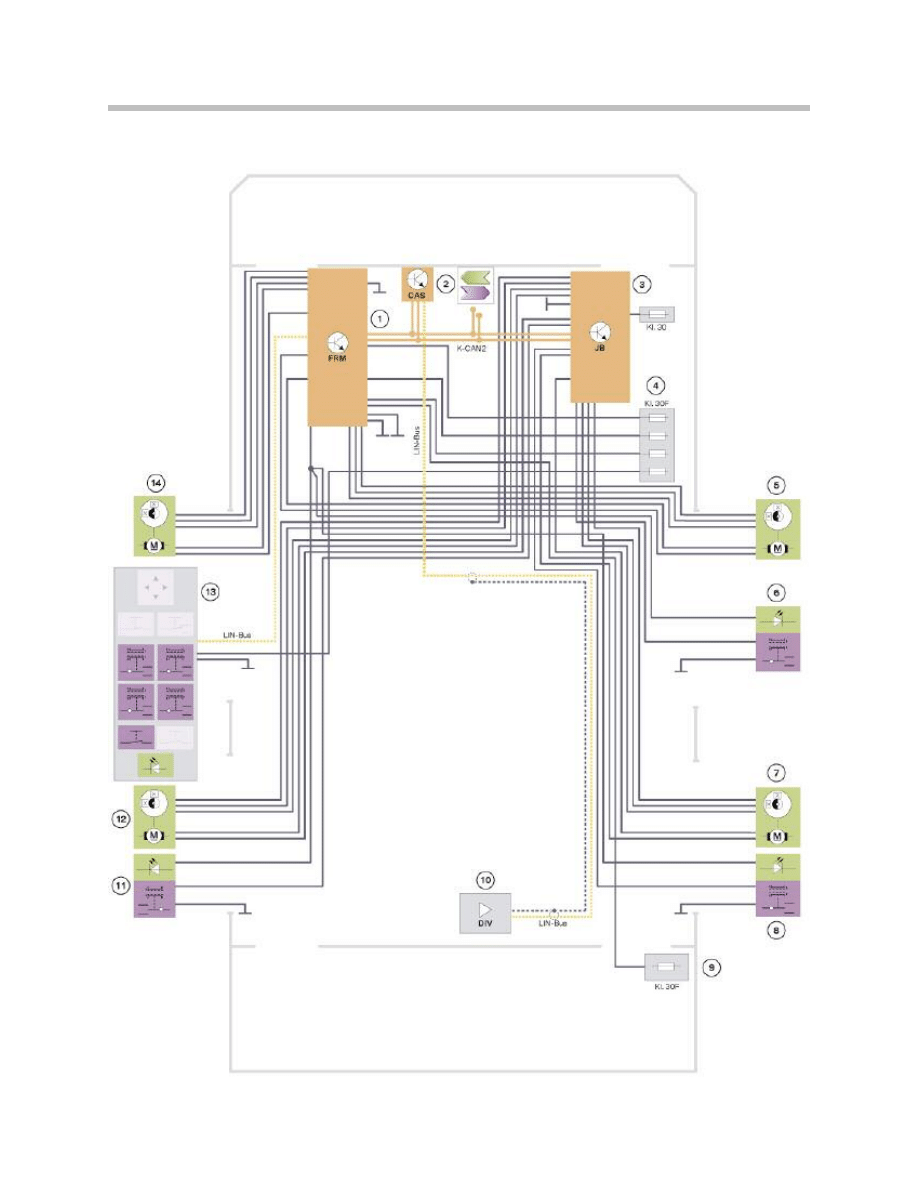
System Circuit Diagram - Power Windows
6
F01 Power Windows

The Car Access System (2) issues the enable to actuate the power window motors (5, 7,
12 and 14). If a power window switch is then activated, the footwell module (1) (front
power window motor) or the junction box electronics (3) (rear power window motor) exe-
cutes the request.
Examples of the Signal Path
The following examples of a signal path show the path taken by the signal before the
power window motor opens or closes the window. A requirement is that the Car Access
System 4 has issued the enable to operate the power windows.
Driver’s Door Switch Cluster
When the power window switch for the window in the driver’s door or front passenger ‘s
door is operated, the signal is routed via the LIN bus to the footwell module. The footwell
module drives the corresponding power window motor.
The signal is routed from the driver’s door switch cluster via the LIN bus to the footwell
module when the power window switches for the windows in the rear doors are operated.
The footwell module sends the signal via the K-CAN2 to the junction box electronics.
The junction box electronics receives the signal and activates the corresponding power
window motor.
Power Window Switch, Front Passenger’s Door
The signal is routed to the junction box electronics when the power window switch in the
front passenger’s door is operated.
The junction box electronics sends the signal via the K-CAN2 to the footwell module.
The footwell module drives the power window motor.
Power Window Switch, Rear Doors
When the power window switches in the rear doors are operated, the signal is routed to
the JBE. The JBE drives the power window motor.
7
F01 Power Windows
Index
Explanation
Index
Explanation
1
Footwell module (FRM)
10
Remote control receiver in diversity module
2
Car Access System 4 (CAS 4)
11
Power window switch, driver’s side rear
3
Junction box electronics (JB)
12
Power window motor with indirect pressure-sen-
sitive finger guard on rear driver’s side
4
Front power distribution box
13
Driver’s door switch cluster
5
Power window motor with indirect pressure-
sensitive finger guard on front passenger’s side
14
Power window with indirect pressure-sensitive
finger guard on driver’s door
6
Power window switch, passenger side front
K-CAN2
Body-CAN2
7
Power window motor with indirect pressure-
sensitive finger guard on rear passenger’s side
LIN-Bus
Local Interconnect Network bus
8
Power window switch, passenger side rear
Kl. 30
Terminal 30
9
Rear power distribution box
Kl. 30F
Terminal 30, fault switched

Overview
All four windows on the F01/F02 are electrically operated. The power windows are
equipped with an indirect pressure-sensitive finger guard. The electric power windows
have the following functions:
• Opening and closing
• Opening and closing with toll function
• Auto-remote opening and closing
• Indirect pressure-sensitive finger guard
• Panic mode
• Load shut-down at terminal 50
• Overheating protection of power window motors.
Opening and Closing
The Car Access System 4 has the central control function for electric opening and clos-
ing of the power windows.
This means that the Car Access System 4 issues the enable to open and close the
power windows. The footwell module and the junction box electronics actuate the power
window motors and monitor the motor speed of the respective power window motor. This
means the footwell module or the junction box electronics can respond to the following
operating situations:
• Trapping
• Overheating of the power window motor
• Blocking of power window motors.
The corresponding power window motor is activated in OPEN or CLOSE direction by
pressing or pulling the power window switches to the first notch position. The power win-
dow motor remains active until the corresponding power window switch is released.
To ensure the power window is closed reliably, the power window motor is briefly driven
to block status at the upper stop.
Opening and Closing with Toll Function
The toll function is implemented for all power windows. The corresponding power win-
dow motor is driven in the OPEN or CLOSE direction by pressing or pulling a power win-
dow switch beyond the limit stop.
The power window motor moves the window automatically until it is completely open or
closed. Power window operation is stopped when the power window switch is pressed or
pulled again.
8
F01 Power Windows
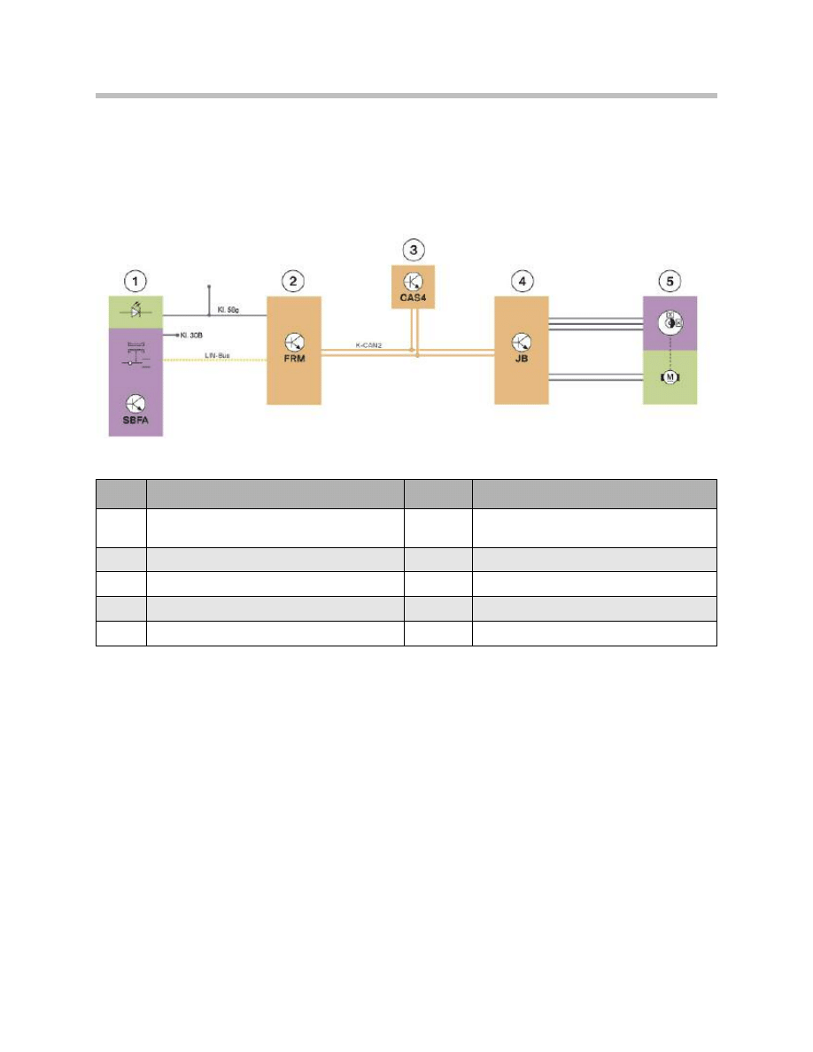
By way of example, the opening and closing procedure for one of the rear windows is
illustrated by the signal path in the following graphic. The opening or closing function is
initiated from the driver’s door switch cluster.
9
F01 Power Windows
Index
Explanation
Index
Explanation
1
SBFA power window switch in
driver's door switch cluster
LIN-Bus
LIN-bus
2
Footwell module (FRM)
K-CAN2
Body-CAN2
3
Car Access System 4 (CAS 4)
Kl. 30B
Terminal 30, basic operation
4
Junction box electronics (JB)
KL. 58g
Terminal 58g
5
Power window motor
Example - Opening or closing the rear window in the F01/F02

Auto-remote Opening and Closing
Auto-remote opening or closing can be performed with the identification transmitter via
the door lock in the driver’s door or the outside driver’s/passenger’s door handle.
Auto-remote opening with identification transmitter
The auto-remote opening function is initiated by unlocking the vehicle with the identifica-
tion transmitter and keeping the button pressed for longer than 5 seconds.
Initially, the front windows are opened, followed after a short time delay by the rear win-
dows and the panorama glass roof.
Note: If the fold-in/out exterior mirrors option is installed and the mirrors are
folded in, the mirrors will be folded out at the same time as the rear win-
dows are opened.
Only the version sold in Japan offers auto-remote closing or auto-
remote opening for folding the exterior mirrors in or out.
The signal from the identification transmitter is picked up by the Car Access System 4 via
the remote control receiver.
The Car Access System 4 issues the enable to operate the power windows and initiates
the auto-remote opening function. The footwell module and the junction box electronics
correspondingly activate the power window motors.
Auto-remote closing with identification transmitter
The auto-remote closing function is initiated after locking the vehicle with the identifica-
tion transmitter and keeping the button pressed for longer than 5 seconds. Initially, the
panorama glass roof is closed followed after a short time delay by the rear/front windows.
If the folding exterior mirrors option is installed, the mirrors are folded in simultaneously as
the rear windows are closed.
Auto-remote opening and closing via the driver’s door lock barrel
There are two Hall sensors installed in the door lock for the purpose of opening and clos-
ing the vehicle. The Hall sensors enable the footwell module to detect the position of the
mechanical key or of the spare key in the lock barrel.
The key must be turned to the open or close position to initiate the auto-remote opening
and closing function. The auto-remote opening or closing function is initiated when the
key is held in this position.
The footwell module sends the request via the K-CAN. On conclusion of the correspond-
ing check, the Car Access System 4 initiates the auto-remote opening or closing proce-
dure.
Auto-remote closing with Comfort Access
In connection with Comfort Access, the auto-remote closing function is triggered via the
driver’s/passenger’s outside door handle.
10
F01 Power Windows
11
F01 Power Windows
It is sufficient to touch the sensitive area of the outside door handle in order to trigger the
auto-remote closing function via the door handle. Auto-remote closing is triggered if the
sensitive area is touched for longer than 5 seconds. The ID transmitter must be within an
approximate 2 m radius of the vehicle.
Note: Touching the outside door handle corresponds to pressing the lock but-
ton on the ID transmitter.
Indirect Pressure-sensitive Finger Guard
Essentially, the indirect pressure-sensitive finger guard does not prevent an object being
trapped but rather it limits the trapping force to maximum 80 N. The power window motor
is reversed on exceeding this trapping force.
The footwell module and the junction box electronics monitor the activated power win-
dow motors. The indirect pressure-sensitive finger guard for the front windows is activat-
ed by the footwell module. The indirect pressure-sensitive finger guard for the rear win-
dows is activated by the junction box electronics.
The indirect pressure-sensitive finger guard in the E90 is based on the evaluation of the
Hall pulses from the power window motors. The speed is derived from the Hall pulses of
the power window motors. Speed fluctuations within certain ranges trigger the indirect
pressure-sensitive finger guard so that the windows are opened. Operation of the power
window switches is ineffective while the windows are in the process of opening.
If no operable pressure-sensitive finger guard is detected as the result of defective Hall
sensors, the window can only be operated in jolts. The power window is in emergency
mode and must be reinitialized.
Note: The initialization procedure is described in the Service Information.
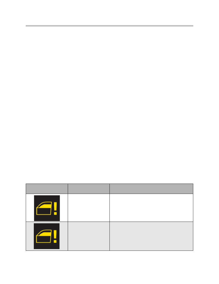
The customer is shown a Check Control message.
Check Control
message
Meaning
Information on the central information display
Power window pres-
sure-sensitive finger
guard!
Power window pressure-sensitive finger guard
deactivated.
Power window pres-
sure-sensitive finger
guard!
Power window pressure-sensitive finger guard failed.
Ask your nearest BMW Service to check this.

Panic Mode
Panic mode is triggered by overpulling releasing-overpulling (overpulling = pulling beyond
limit stop) the power window switches.
It is necessary to release and overpull the switch again as the pressure-sensitive finger
guard is still active the first time the switch is overpulled. Overpulling the power window
switch the second time within 4 seconds closes the window with maximum force.
Note: The indirect pressure-sensitive finger guard is no longer active in this
case. The window closes at the maximum closing force and does not
reverse.
Load shut-down, Terminal 50
Car Access System 4 sends the “terminal 50 ON” status. The signal is received by the
footwell module and junction box electronics via K-CAN.
The junction box electronics and the footwell module prevent operation of the power win-
dows during the start procedure or interrupt current operation of the power windows.
This protects the battery during the starting procedure.
The power window switches must be pressed again following an interruption in opera-
tion.
Operation of the power windows is not possible until the start procedure has been com-
pleted.
Overheating Protection of Power Window Motors
The footwell module and the junction box electronics monitor the motor temperature.
The motor temperature is determined based on the outside temperature, motor running
time and the time the motor is stationary (not operative). Each motor can be switched off
individually to prevent the power window motors overheating during operation of the
power windows. The motor is then deactivated for a defined period of time.
The overheating protection facility does not prevent the windows being opened in the
case of trapping. Once started, a power window function is not interrupted by the over-
heating protection facility. In panic mode the window can still be closed even when the
overheating protection function is active.
12
F01 Power Windows
Roller Sun Blind
Roller sun blinds are available as an option for the rear window and rear side windows.
The roller sun blinds can be raised and lowered electrically.
The switch for the roller sun blind on the rear window is located in the driver’s door
switch cluster. The footwell module detects the switch status via the LIN-bus. When the
button is pressed, the footwell module issues the operational request via the K-CAN2.
The complete control and function monitoring facility is integrated in the junction box
electronics. The junction box electronics therefore executes the operational request.
Every time the roller sun blinds are operated, their positions are stored in the junction box
electronics.
Other operating points are located in the armrests on the rear doors. The switches are
located next to the switches for the power windows.
Three switches are provided in each armrest. The switches are:
• Switch for roller sun blind on rear window
• Switch for roller sun blind on left side window
• Switch for roller sun blind on right side window.
The roller sun blinds can be raised and lowered separately with the switches.
13
F01 Power Windows
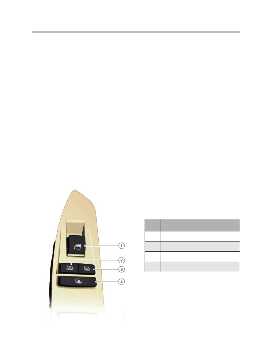
Switch cluster in driver’s side armrest
Index
Explanation
1
Power window switch
2
Switch for roller sun blind on left side window
3
Switch for roller sun blind on right side window
4
Switch for roller sun blind on rear window

Each rear door has two roller sun blinds, one for the side window and one for the quarter
light.
Both roller sun blinds are raised or lowered by means of an electric motor.
Note: The roller sun blinds are raised and lowered completely. They cannot be
raised or lowered to an intermediate position.
If a new operational request is sent to the roller sun blinds during their actuation, they will
reverse their direction of movement immediately.
The enable for operating the roller sun blinds on the rear doors is linked to the closed
window position.
The Car Access System issues the enable for operating the roller sun blinds.
The roller sun blind of the corresponding side window is automatically lowered in
response to an operational request to open the side window.
Operation of the roller sun blinds is restricted in the event of undervoltage.
By monitoring the outside temperature and interior temperature, the function “lower”
roller sun blind is executed at an interior temperature > 11°C and outside temperature < -
16°C.
The roller sun blinds can be operated as from terminal 15N ON.
Note: Operation of the roller sun blinds is disabled when the child safety lock
is activated.
14
F01 Power Windows

15
F01 Power Windows
NOTES
PAGE
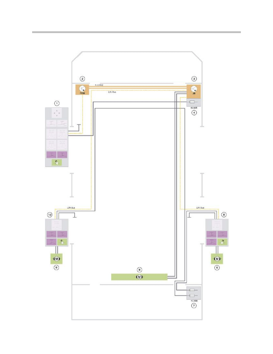
System Circuit Diagram - Roller Sun Blind
16
F01 Power Windows

17
F01 Power Windows
Index
Explanation
Index
Explanation
1
Driver's door switch cluster
8
Motor for roller sun blind, rear window
2
Footwell module (FRM)
9
Switch cluster in rear driver's side door
3
Junction box electronics (JB)
10
Motor for roller sun blind, rear driver's side
4
Front power distribution box
K-CAN2
Body-CAN2
5
Switch cluster in rear passenger's side door
LIN-Bus
Local Interconnect Network bus
6
Motor for roller sun blind, rear passenger's side
Kl. 30B
Terminal 30, basic operation
7
Rear power distribution box

Overview of Functional Principle
The functional principle of the electrically operated roller sun blinds is described in the
following.
Pressure-sensitive Finger Guard for Side Window
The roller sun blind has no electronic pressure-sensitive finger guard! The mechanism
and drive units are designed such as to rule out any danger for the occupants posed by
excessively high forces.
Nevertheless, to prevent trapping, the roller sun blinds can only be extended when the
corresponding side window is closed. However should a trapping situation occur, move-
ment of the roller sun blind will be stopped. The roller sun blind is then moved in the
opposite direction in response to the next operational request. It is always possible to
retract the roller sun blinds at the side windows.
The direction of roller sun blind movement that has already started can only be reversed
1.5 seconds after the button is pressed again.
Further button operation is ignored during the initial 1.5 seconds of roller sun blind move-
ment. This function is intended to protect the operating mechanism of the roller sun
blind.
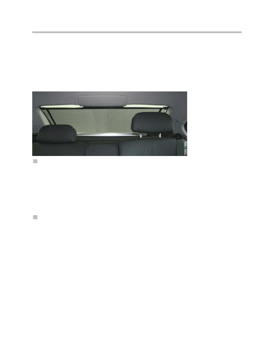
Roller Sun Blind on Rear Window
The roller sun blind on the rear window can be operated by means of the roller sun blind
switches. There are three operating points:
• Driver’s door switch cluster
The junction box electronics receives the switch status via the K-CAN2.
• Switch cluster in rear driver’s side armrest*
• Switch cluster in rear passenger’s side armrest*.
*The junction box electronics cyclically evaluates the switches at the rear doors via the LIN-bus.
The roller sun blind for the rear window is raised or lowered by briefly pressing the switch.
A special function is activated when the switch for the rear window roller sun blind is
pressed longer. This special function allows all three roller sun blinds to extend or retract
to assume the same position.
In this function, the roller sun blind for the rear window is actuated and, if necessary, also
the roller sun blinds for the side windows.
Every time the roller sun blinds are operated, their positions are stored in the junction box
electronics.
The end stops are detected by the motors blocking, thus cancelling activation.
18
F01 Power Windows
A repeat inhibit function is integrated in the system to prevent the motor overheating due
to continuous operational requests initiated by children playing with the switch. The
repeat inhibit blocks operation of the roller sun blind in the down position. Once started,
movement of the roller sun blind is not interrupted by the repeat inhibit.
The renewed enable to raise the roller sun blind depends on the number of times the
roller sun blind is operated and the intervals between operation.
Position of roller sun blinds unknown
The raised or lowered positions of the roller sun blinds are stored in the junction box elec-
tronics. An unknown position of the roller sun blind may occur, for example, as a result of
a voltage reset. If the position is not known, the junction box electronics interprets the
roller sun blind as being in the raised position. The roller sun blind is then initially lowered
in response to the next operational request. The direction is reversed if the junction box
electronics detects blocking directly after actuation. Blocking signals that the roller sun
blind is at the lower end stop position.
Blocking detection
The junction box electronics is equipped with a blocking detection facility to protect the
motor. This function serves the purpose of immediately switching off the motor on reach-
ing the upper or lower end position.
Motor actuation is additionally subject to a time monitoring function. Consequently, actu-
ation of the motors is terminated after a defined maximum period of time.
The roller sun blinds on the side windows also feature a blocking detection function. This
function is integrated in the electronic circuitry of the switch cluster in the rear door arm-
rest.
This blocking detection function serves the purpose of switching off the motor on reach-
ing the upper or lower end position.
The end positions are detected by evaluating the current consumption of the motors,
thus cancelling activation. After detecting a significant increase in current consumption,
the motor is short-circuit braked in blocked position and the drive is briefly reversed to
relief the strain on the mechanical system.
19
F01 Power Windows
Rear window roller sun blind F01/F02

20
F01 Power Windows
The actuation time of the motor for the roller sun blind is additionally monitored. The
actuation time is limited to 15 seconds. Actuation is then terminated after this period of
time has elapsed.
Child safety lock
The child safety lock function is switched on or off by means of the child safety lock
switch in the switch cluster on the driver’s side.
The roller sun blinds can no longer be operated with the rear switches when the child
safety lock is switched on.
No request to raise or lower the roller sun blind is triggered when the child safety lock
button is pressed. Current movement of the roller sun blind is not interrupted when the
child safety lock is engaged.
Roller sun blind switches
All switches have a LIN-bus connection. The switches are connected to terminal 30B
and a ground connection.
The motors for the roller sun blinds in the side windows are connected directly to the
respective switch cluster. The motor for the roller sun blind on the rear window is con-
nected to the junction box electronics.
The electronic circuitry for the LIN-bus and the power electronics for actuation of the
motors are integrated in the switch cluster. The electronic circuitry monitors actuation and
detects the end positions of the roller sun blind.
The junction box electronics receives information on the end positions from the LIN-bus.

21
F01 Power Windows
NOTES
PAGE
Components Involved
The following graphic shows all the components of the power window system together
with the respective control units and control elements.
The following components are described:
• Controls
• Control units
– Car Access System 4
– Footwell module
– Junction box electronics
• Power window motor
22
F01 Power Windows
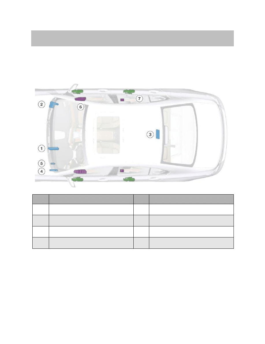
System Components
Index
Explanation
Index
Explanation
1
Car Access System 4
5
Central gateway module
2
Junction box electronics
6
Power window switch
3
Remote control receiver in diversity module
7
Power window motors
4
Footwell module
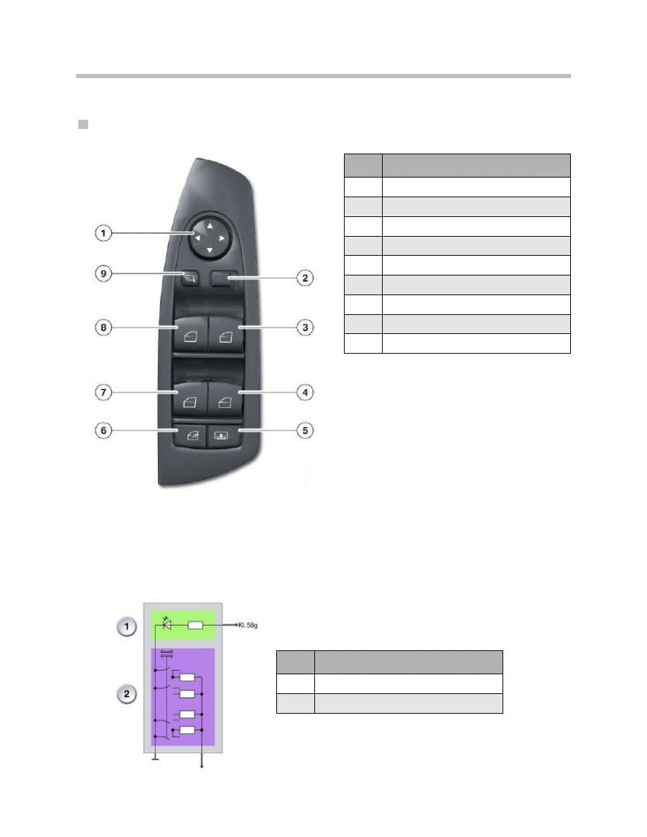
Controls
Driver’s door switch cluster
The driver’s door switch cluster is connected via the LIN bus to the footwell module.
For opening or closing, the power window switch has two notch positions. The first notch
position is used for the manual power window function. The second notch position
(press) is used for the toll function of the power windows.
The power window switches are resistance-coded and switched to ground. The following
graphic shows the principle of a resistance-coded switch.
Resistance-coded switch F01/F02
23
F01 Power Windows
Index
Explanation
1
Outside mirror adjustment switch
2
Selector switch, outside mirror left/ right
3
Power window button, passenger's door
4
Power window button, rear right
5
Roller sun blind button
6
Child safety lock button
7
Power window button, rear left
8
Power window button, driver's door
9
Outside mirror fold-in button
Index
Explanation
1
Illumination of power window switch
2
Resistance-coded switch

Signal evaluation of the power window switches
The signals of the power window switch in the driver’s door switch console are evaluated
directly by the driver’s door switch cluster and transferred to the footwell module via the
LIN bus.
The signals from the power window switches in the front passenger’s door as well as the
power window switches of both rear doors are evaluated by the junction box electronics.
Control Units
Car Access System 4
The Car Access System 4 is the central control unit for opening and closing the windows.
Therefore, it issues the enable to operate the power windows.
“Terminal 50 ON” status is sent while starting the engine. The junction box electronics
and the footwell module prevent operation of the power windows during the start proce-
dure or interrupt current operation of the power windows. This means more energy from
the battery is available for the starter during engine start-up.
Footwell module
The relays for the power window motors for the front doors are installed in the footwell
module.
The footwell module provides information on the status of the door contacts and the dri-
ver’s door lock cylinder.
The footwell module also provides the power window switch and the driver’s door switch
console with information on the “Terminal 58g ON” status.
Junction box electronics
The relays for the power window motors for the rear doors are installed in the junction box
electronics.
Identification Transmitter
The identification transmitter can initiate auto-remote opening/closing of the power win-
dows.
The operating procedure is defined in the Owner’s Handbook.
Power Window Motors
The power window motors are equipped with Hall sensors that generate signals during
motor operation. These signals serve the purpose of monitoring motor operation and are
evaluated for the pressure-sensitive finger guard.
The signals are evaluated in the footwell module and the junction box electronics.
24
F01 Power Windows

Initialization
Initialization of Power Windows
The front and rear power windows can be initialized via the power window switches or
the BMW diagnosis system.
Note: The power windows can only be moved in jolts if not initialized.
Initialization via the power window switches
The following procedure must be performed to initialize the system:
• Completely close window by pulling the power window switch beyond the limit
stop.
• Briefly interrupt pulling the power window switch and then pull the switch upwards
again for approximately 1 second.
Initialization via the BMW diagnosis system
The power windows can be initialized as part of an initialization job using the diagnosis
system. A detailed description of the initialization procedure is provided in the BMW
diagnosis system.
25
F01 Power Windows
Service Information
Document Outline
- Main Menu
- 01_F01 Introduction
- 02_F01 Powertrain
- 03_F01 Voltage Supply & Bus Systems
- 03.1_F01 Bus Systems
- 03.2_F01 Voltage Supply
- 03.3_F01 Energy Management
- 03.4_F01 Car Access System 4
- 04_F01 Chassis Dynamics
- 04.1_F01 Chassis and Suspension
- 04.2_F01 Dynamic Driving Systems
- 04.3_F01 Longitudinal Dynamics Systems
- 04.4_F01 Lateral Dynamics Systems
- 04.5_F01 Vertical Dynamics Systems
- 04.6_F01 Cruise Control Systems
- 05_F01 General Vehicle Electronics
- 05.1_F01 Comfort Access
- 05.2_F01 Central Locking System
- 05.3_F01 Automatic Soft Close
- 05.4_F01 Power Windows
- 05.5_F01 Sliding Tilting Sunroof
- 05.6_F01 Anti-theft System
- 05.7_F01 Automatic Luggage Compartment Lid
- 05.8_F01 Exterior Lighting
- 05.9_F01 Interior Lighting
- 05.10_F01 Wiper-Washer System
- 05.11_F01 Exterior Rear View Mirrors
- 05.12_F01 Seats
- 05.13_F01 Steering Column Switch Cluster
- 06_F01 Driver Information Systems
- 06.1_F01 Displays Indicators and Controls
- 06.2_F01 Head-up Display
- 06.3_F01 BMW Night Vision 2
- 06.4_F01 Active Blind Spot Detection System
- 06.5_F01 KAFAS
- 06.6_F01 PDC-TRSVC
- 07_F01 Information and Communication Technology
- 07.1_F01 Rear Seat Entertainment Systems
- 07.2_F01 Telephone System
- 07.3_F01 Voice Activation System
- 07.4_F01 Audio Systems
- 08_F01 Climate Control
- 09_F01 Passive Safety Systems
- 10_F01 Service Information
- 10.1_F01 System Functions
- 10.2_ISTA-Programming
Wyszukiwarka
Podobne podstrony:
Popular Mechanics Repairing Power Windows
r-dod.B.05, ## Documents ##, Bezpieczeństwo w Windows 2000. Czarna księga
r-04.05, ## Documents ##, Bezpieczeństwo w Windows 2000. Czarna księga
r-11.05, ## Documents ##, Bezpieczeństwo w Windows 2000. Czarna księga
r-00.05, ## Documents ##, Bezpieczeństwo w Windows 2000. Czarna księga
r-02.05, ## Documents ##, Bezpieczeństwo w Windows 2000. Czarna księga
r-07.05, ## Documents ##, Bezpieczeństwo w Windows 2000. Czarna księga
r-05.05, ## Documents ##, Bezpieczeństwo w Windows 2000. Czarna księga
r-10.05, ## Documents ##, Bezpieczeństwo w Windows 2000. Czarna księga
r-08.05, ## Documents ##, Bezpieczeństwo w Windows 2000. Czarna księga
r-01.05, ## Documents ##, Bezpieczeństwo w Windows 2000. Czarna księga
Power Window
r-12.05, ## Documents ##, Bezpieczeństwo w Windows 2000. Czarna księga
Power Window Circuit (1 of 2)
05 6 F01 Anti theft System
power windows
05 1 F01 Comfort Access
96ZJ 8S POWER WINDOW SYSTEMS
więcej podobnych podstron