
Initial Print Date: 12/06
Table of Contents
Subject
Page
Professional Radio (CHAMP) . . . . . . . . . . . . . . . . . . . . . . . . . . . . . . . . . . . . . . . . . . . . . . . . . . . . . . . . . . . . . . . . . . . . . . . . . . . . . . . .4
Professional Radio with NAV (CCC) . . . . . . . . . . . . . . . . . . . . . . . . . . . . . . . . . . . . . . . . . . . . . . . . . . . . . . . . . . . . . . . . . . . . . . . . . . .4
Amplifiers and Speakers . . . . . . . . . . . . . . . . . . . . . . . . . . . . . . . . . . . . . . . . . . . . . . . . . . . . . . . . . . . . . . . . . . . . . . . . . . . . . . . . . . . .5
Roof Antenna . . . . . . . . . . . . . . . . . . . . . . . . . . . . . . . . . . . . . . . . . . . . . . . . . . . . . . . . . . . . . . . . . . . . . . . . . . . . . . . . . . . . . . . . . . . . .16
Rear Seat Entertainment (RSE) . . . . . . . . . . . . . . . . . . . . . . . . . . . . . . . . . . . . . . . . . . . . . . . . . . . . . . . . . . . . . . . . . . . . . . . . . . . . .18
E70 Audio Systems Workbook
Revision Date:

Table of Contents
Subject
Page
BLANK
PAGE

Audio Systems
Model:
E70
Production: From Start of Production
E70 Audio Systems Workbook
3
After completion of this module you will be able to:
• Demonstrate the different functions of the Audio System on the E70.
• Identify the components on the E70 Audio System.
The US vehicles are equipped with the new head unit platform
called CHAMP (Central Head unit and Multimedia Platform) The
CCC (Car Communication Computer) is available as the head unit
for the Professional navigation system. The head units offer eight
favorites buttons.
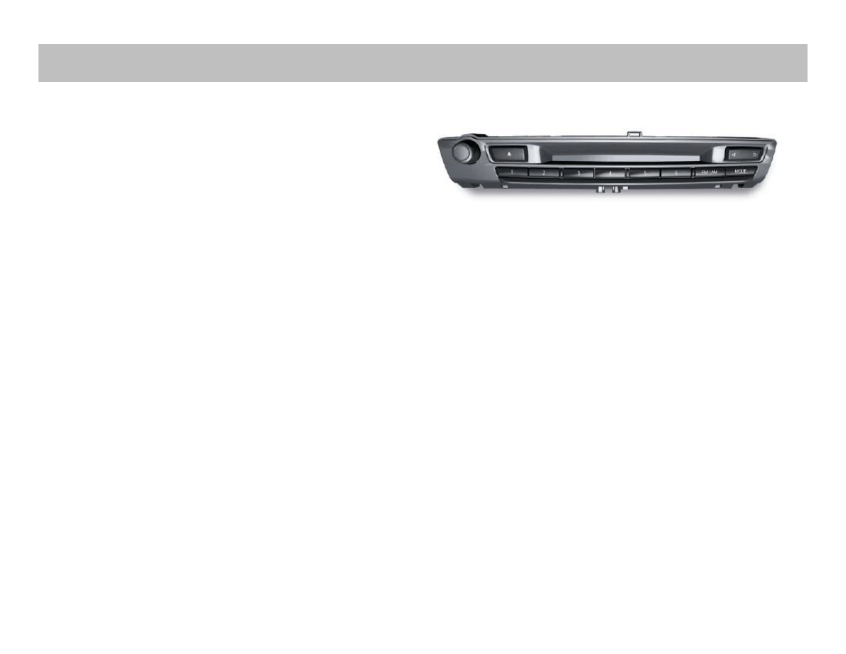
Professional Radio (CHAMP)
The CHAMP and CCC have eight favorite buttons, six assignable
favorites buttons. Button 7 is assigned with FM/AM selection, but-
ton 8 is for toggling the operating mode.
CHAMP combines the following control modules in the one housing:
• RDS double tuner
• Audio system controller
• Gateway between MOST and K-CAN
• Interface to the Central Information Display.
CHAMP system can be used to control:
• Communication
• Entertainment
• Air conditioning (climate control)
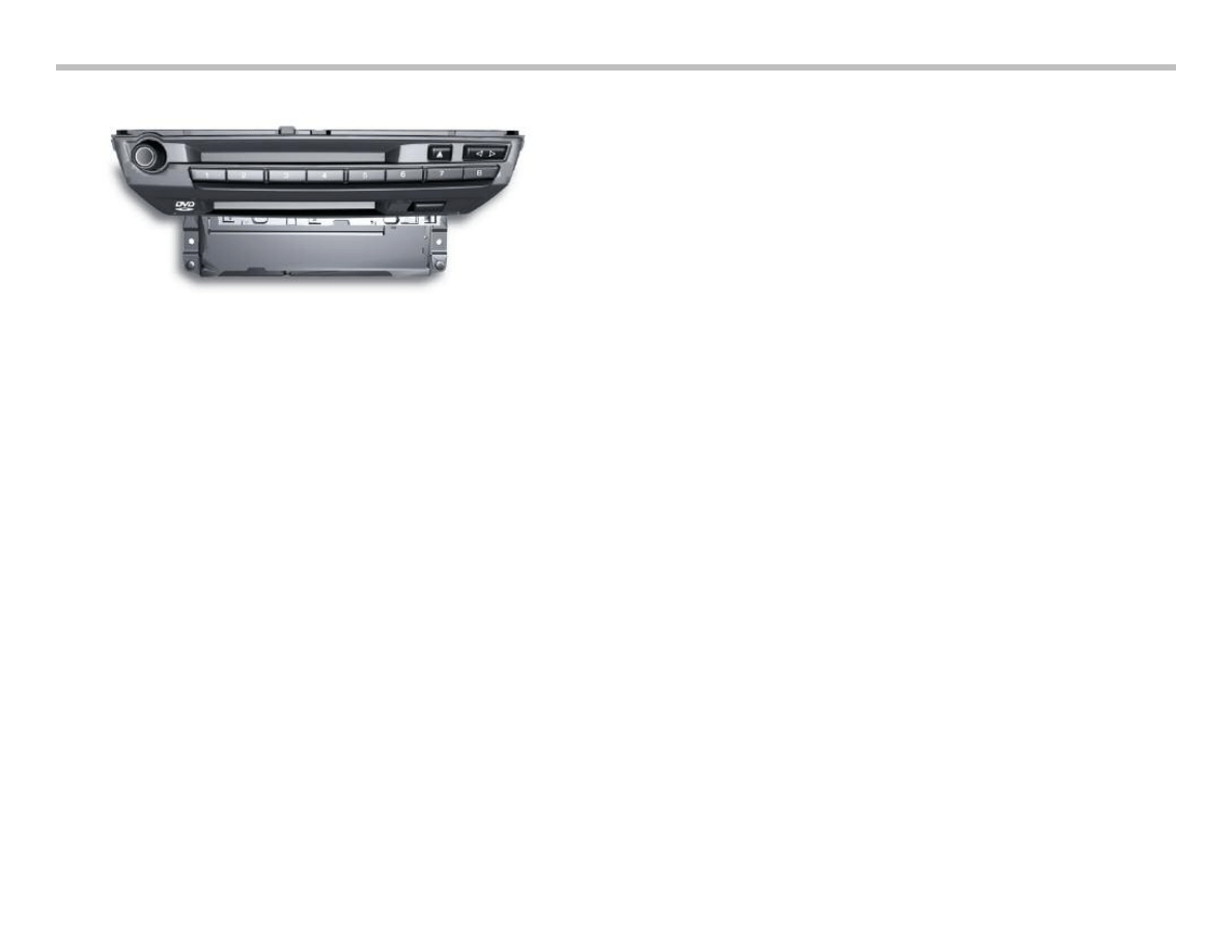
Professional Radio with NAV (CCC)
Note: Button 7 is assigned with FM/AM selection,
button 8 is for toggling the operating mode
The CCC combines the following control modules in one housing:
• Navigation computer/GPS module; map view and/or cursor
view in the CID
• RDS double tuner
• Audio system controller
• Gateway between MOST and K-CAN
• Interface to control display (LVDS).
Two drives are integrated in the housing:
• DVD player
• CD player
4
E70 Audio Systems Workbook
Audio Systems
E70 Audio Systems Workbook
5
When the navigation system is not in use, its DVD drive can be
used to play audio CDs. The playback of video files is not support-
ed.The system can be used to control:
• Communication
• Entertainment
• Navigation
• Air conditioning (climate control)
• Settings (5th menu).The MP3 directory structure corresponds
to that of a PC. There is no limit to the number of directories,
sub-directories and music tracks that the CCC can support.
However, the time taken for the drive to read the contents of
the CD when the CD is inserted is longer, depending on how
much data is stored on the CD.
Amplifiers and Speakers
The speaker systems in the E70 are, as in other Series, available in
two quality levels:
• HiFi system
• Top-HiFi system.
Even though the diameters of the speakers in the HiFi and Top-
HiFi systems are the same, there are differences in the power out-
put of the speakers. This is achieved through the use of different
materials in the diaphragms, coils and magnets.
The HiFi system achieves double the power of the standard stereo
system. In addition, the HiFi system is equipped with a 7-channel
amplifier with digital equalizer.
The optional Top-HiFi system achieves double the power of the
standard HiFi system and uses a digital 9-channel amplifier.
Optimum audio playback in the vehicle is achieved thanks to com-
plex digital signal processing.
The HiFi system has twelve speakers, five tweeters, five mid-range
and two central bass speakers. The HiFi amplifier is woken by the
Rad_On signal sent by hard wire from the Head unit and uses a
K-CAN connection for diagnostics and coding.
The Top-HiFi system has 16 speakers, seven tweeters, seven mid-
range speakers and two central bass speakers. The Top-HiFi ampli-
fier is connected to the MOST.
The central bass speakers are located under the front seats. They
are coupled to the side sills to increase the resonance volume nec-
essary for bass reproduction.
The CHAMP and the CCC (navigation system) can be combined
with any of the amplifier/speaker systems, provided the specific
national variants are taken into consideration.
Note: CHAMP receives the terminal 58g (lighting) signal
via hard wire. The CCC receives it via the K-CAN.
6
E70 Audio Systems Workbook
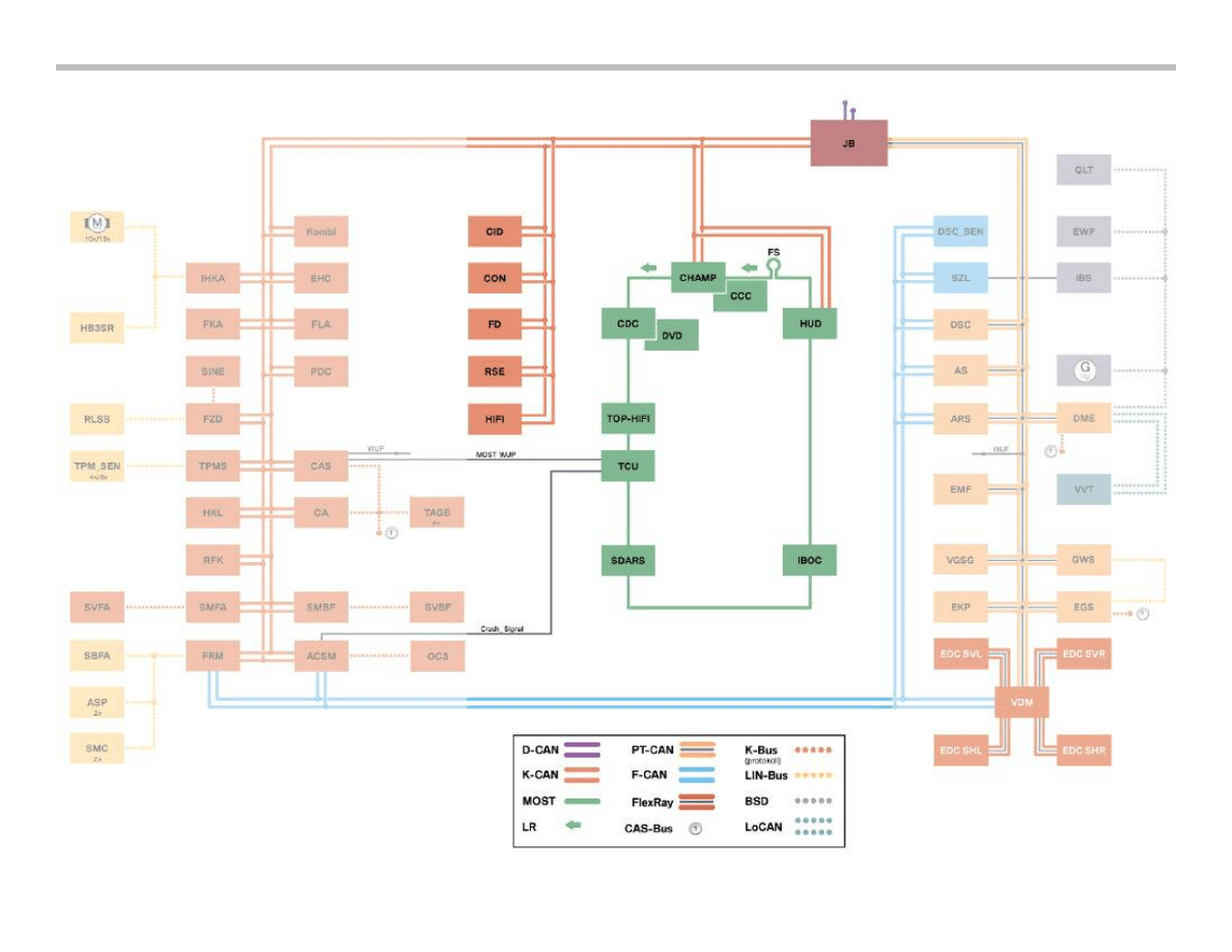
System Bus Overview
E70 Audio Systems Workbook
7
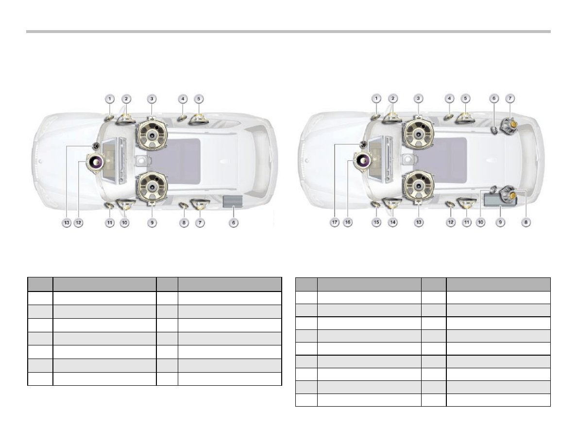
Top-HiFi System
Index
Explanation
Index
Explanation
1
Tweeter, front right door
8
Tweeter ,rear left door
2
Mid-range speaker, front right door
9
Central bass speaker, left
3
Central bass speaker, right
10
Mid-range speaker, front left door
4
Tweeter, rear right door
11
Tweeter, front left door
5
Mid-range speaker ,rear right door
12
Mid-range speaker, front center
6
HiFi amplifier
13
Tweeter, front center
7
Mid-range speaker, rear left door
Index
Explanation
Index
Explanation
1
Tweeter ,front right door
10
Tweeter ,D-pillar left
2
Mid-range speaker, front right door,
11
Mid-range speaker,rear left door
3
Central bass speaker, right
12
Tweeter, rear left door
4
Tweeter, rear right door
13
Central bass speaker, left
5
Mid-range speaker, rear right door
14
Mid-range speaker, front left door
6
Tweeter,D-pillar right
15
Tweeter, front left door
7
Mid-range speaker, D-pillar right
16
Mid-range speaker, front center
8
Mid-range speaker ,D-pillar left
17
Tweeter, front center
9
Top-HiFi amplifier
HiFi System
8
E70 Audio Systems Workbook
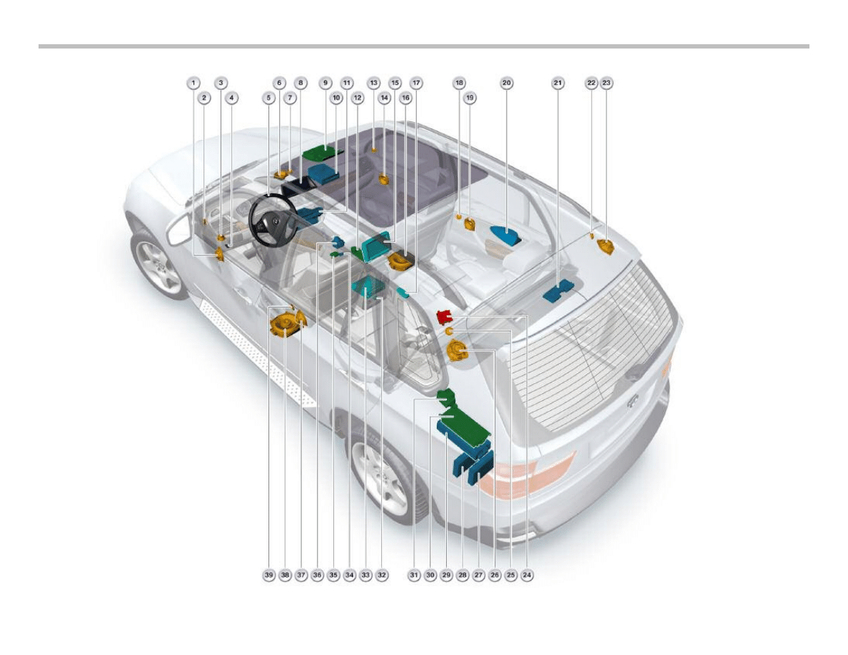
Audio Component Location

E70 Audio Systems Workbook
9
Index
Explanation
Index
Explanation
1
Broadband speaker or medium-range loudspeaker Left-
hand front door
21
Aerial amplifier with diversity module
2
Tweeter, left-hand front door
22
Tweeter, right-hand rear D-post
3
SOS speaker
23
Medium-range loudspeaker, right-hand rear D-post
4
MOST direct access
24
Heated rear window blocking circuit with suppressor fil-
ter for additional brake light
5
Multifunction steering wheel (MFL)
25
Tweeter, left-hand rear D-post
6
Mid-range speaker, front center
26
Medium-range loudspeaker, left-hand rear D-post
7
Tweeter, front center
27
Satellite tuner (SDARS)
8
Central information display (CID)
28
High Definition Radio (IBOC)
9
Roof function center (microphone and emergency call
button)
29
Audio amplifier (HiFi or Top-HiFi)
10
CD changer (CDC)
30
Telematics Control Unit (TCU)
11
Head Unit
31
SOS antenna
12
Snap-in adapter
32
Head phone connectors
13
Tweeter, right-hand front door
33
Rear seat entertainment (RSE)
14
Broadband speaker or medium-range loudspeaker,
right-hand front door
34
Audio jack (AUX-In)
15
Rear display (RD)
35
Bluetooth antenna
16
Central bass speaker, right
36
Controller
17
Radio remote control (RRC) for rear seat entertainment
37
Broadband speaker or medium-range loudspeaker, left-
hand rear door
18
Tweeter, right-hand rear door
38
Central bass speaker, left
19
Broadband speaker or medium-range loudspeaker,
right-hand rear door
39
Tweeter, eft-hand rear door
20
Roof aerial (satellite tuner, GPS, telephone)
10
E70 Audio Systems Workbook
H
iF
i S
y
st
e
m
C
irc
u
it
D
ia
g
ra
m
E70 Audio Systems Workbook
11
To
p
H
iF
i S
y
st
e
m
C
irc
u
it
D
ia
g
ra
m
12
E70 Audio Systems Workbook
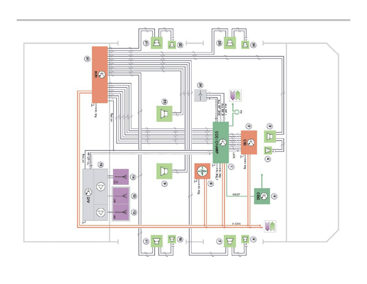
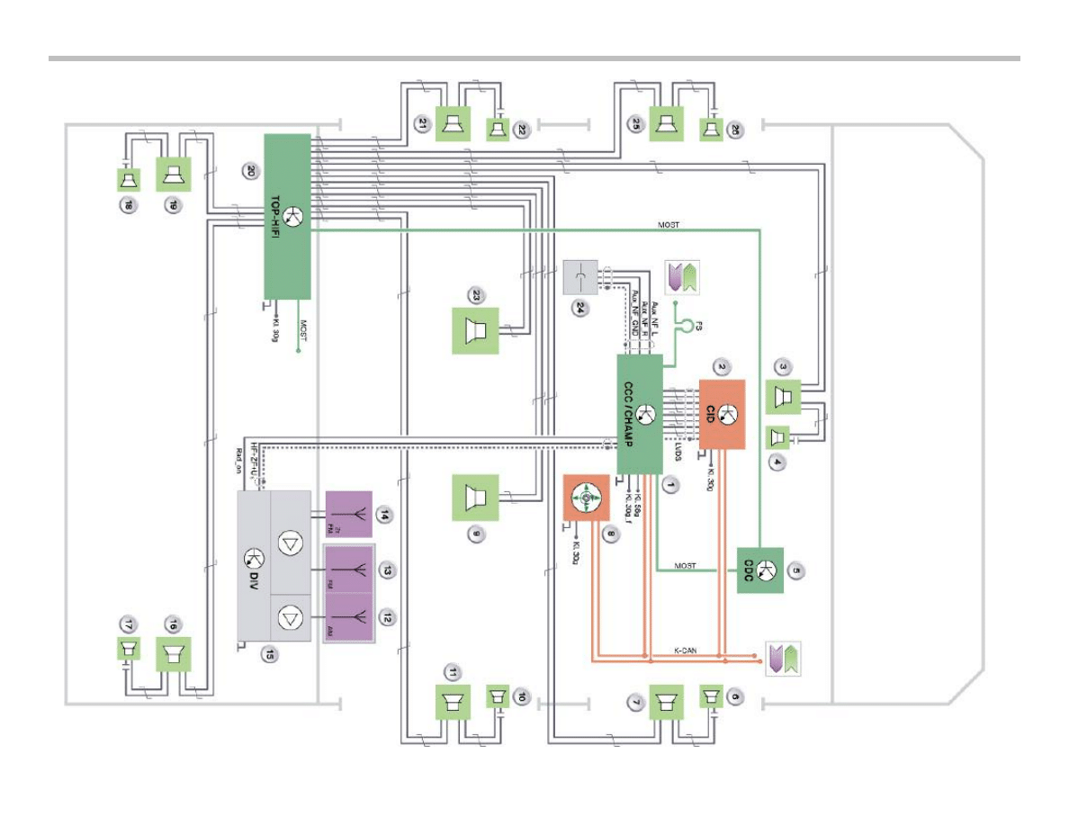
HiFi and Top HiFi Systems Circuit Diagram Legend
Index
Explanation
Index
Explanation
1
Head unit
14
Rear window antennas (FM2, FM3)
2
Central information display
15
Antenna amplifier with diversity module
3
Mid-range speaker, front center
16
Mid-range speaker, D-pillar right
4
Tweeter, front center
17
Tweeter, D-pillar right
5
CD changer
18
Tweeter, D-pillar left
6
Tweeter, front right door
19
Mid-range speaker, D-pillar left
7
Mid-range speaker, front right door
20
Top-HiFi amplifier
8
Controller
21
Mid-range speaker, rear left door
9
Central bass speaker, right
22
Tweeter, rear left door
10
Tweeter, rear right door
23
Central bass speaker, left
11
Mid-range speaker, rear right door
24
Audio jack
12
Rear spoiler antenna (AM)
25
Mid-range speaker, front left door
13
Rear spoiler antenna (FM1)
26
Tweeter, front left door
LVDS
Low voltage differential signal
MOST
Media Oriented System Transport (digital bus)
Aux_NF
Audio input for additional audio sources
FS
MOST direct access
Rad_On
Control signal or power supply
US
Switching voltage
HF
High frequency signal
ZF
Intermediate frequency signal
E70 Audio Systems Workbook
13
Classroom Exercise - Review Questions
Compare the circuit diagrams and check all that apply.
HiFi System
Top HiFi System
Which system uses 16 speakers?
Which system is on K Can Bus?
Which system is on Most Bus?
Which system amplifier requires a hard-wired
Rad _on connection for wake up ?
Which system can be ordered with, CHAMP or CCC?
14
E70 Audio Systems Workbook
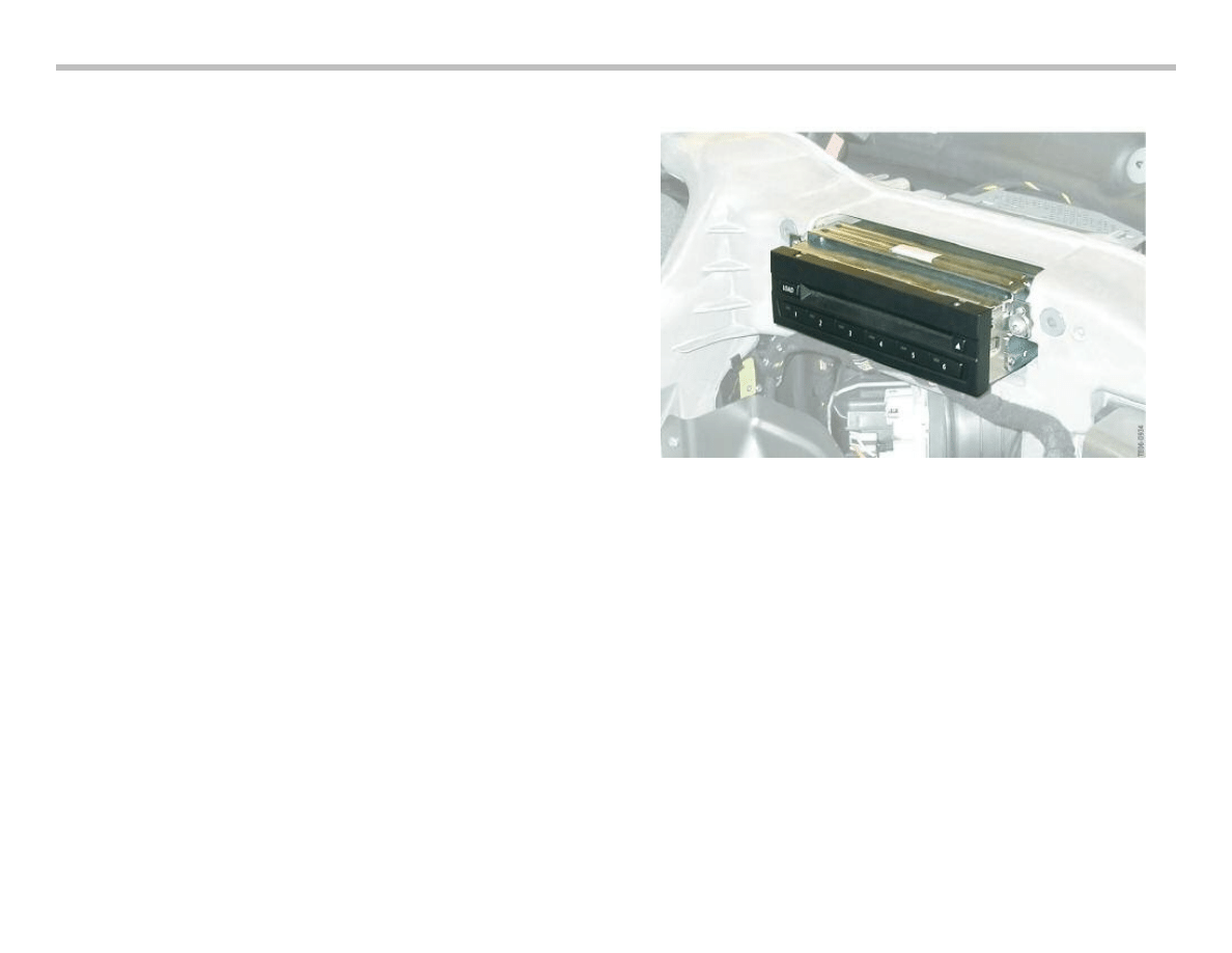
CD Changer
The new 6-disc CD changer (CDC) is available for the E70. The
first time that a single-slot CD changer has been fitted in a BMW
vehicle. It is manufactured by Alpine. The CD changer is located
behind the glove box and it is integrated on the MOST network.
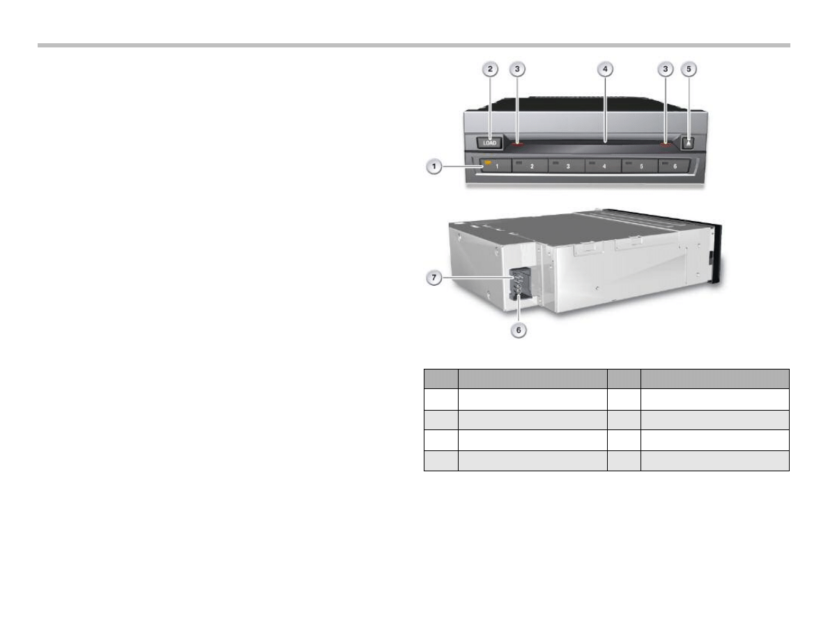
Single-slot CD changer means that the CDs are loaded individually
into the device without a magazine. A CD can be loaded by press-
ing the load button, followed by the button for the operating tray of
the CD to be inserted. If no button is pressed after the load button
has been tapped, the LED in the operating tray button assigned to
the first free tray flashes. In the meantime, the tray moves into posi-
tion.
When the tray is in the correct position, the status display begins to
flash and the CD can be loaded. The contents of the CD are read
as soon as the CD is inserted. The next CD cannot be inserted
until the contents of this CD have been read. The rapid loading fea-
ture must be activated to be able to insert all CDs immediately one
after the other. To do this, the load button must be pressed for
approximately 2 seconds. The LEDs in the operating buttons
assigned to free trays begin to flash. Up to 6 CDs can be inserted
one after the other, depending on the number of trays free. The
contents of the CDs inserted are read either once the final free tray
has been filled, on expiry of a time out or if the load or eject button
is pressed. An individual CD can be ejected by pressing the eject
button followed by the operating button concerned. Pressing and
holding the eject button ejects all the CDs.
The CDs cannot be loaded unless the shutter is open. The status
display flashes when it is possible to insert a disc. Operation is
described in detail in the Owner's Handbook for the vehicle.
CD Changer Location
Note: If the eject button is no longer working, a CD can
be ejected using the diagnostic tester. If the CD is
mechanically jammed in the drive, it is necessary to
send in the CD changer.
E70 Audio Systems Workbook
15
The CD changer supports the following compressed file formats:
• MPEG-1 Layer 3 Audio (MP3) with ID3 tag version 1 and ver-
sion 2
• Windows Media Audio (WMA) with WMA tags
• Advanced Audio Coding (AAC).
The data on the CD is decoded by the CD changer and converted
into the digital MOST format.
With the HiFi System, the digital data on the CD is sent to the head
unit via the MOST, where it is then converted to analogue data and
output via the amplifier and the speakers.
If the Top-HiFi system is installed, the decoded audio data is sent
directly to the Top- HiFi amplifier via the MOST from where it is
output. This direct transmission bypassing the head unit is made
possible because data conversion and sound adjustment take
place exclusively in the Top-HiFi amplifier.
Retrofitting a CD Changer
The fiber optics conductors for connecting the CD changer are
arranged at the fiber optics connector in the luggage compartment
such that they are not incorporated in the MOST ring. After retro-
fitting a CD changer, the fiber optics conductors for the CD chang-
er preparation are unplugged at the fiber optics connector and con-
nected to the MOST ring. It is then necessary to code the entire
vehicle.
Note: For more information refer to the technical training
material on available on TIS.
Index
Explanation
Index
Explanation
1
Buttons for operating trays
5
CD drive eject button
2
Load button for CD drive
6
MOST
3
Status display
7
Power supply
4
CD drive slot
16
E70 Audio Systems Workbook
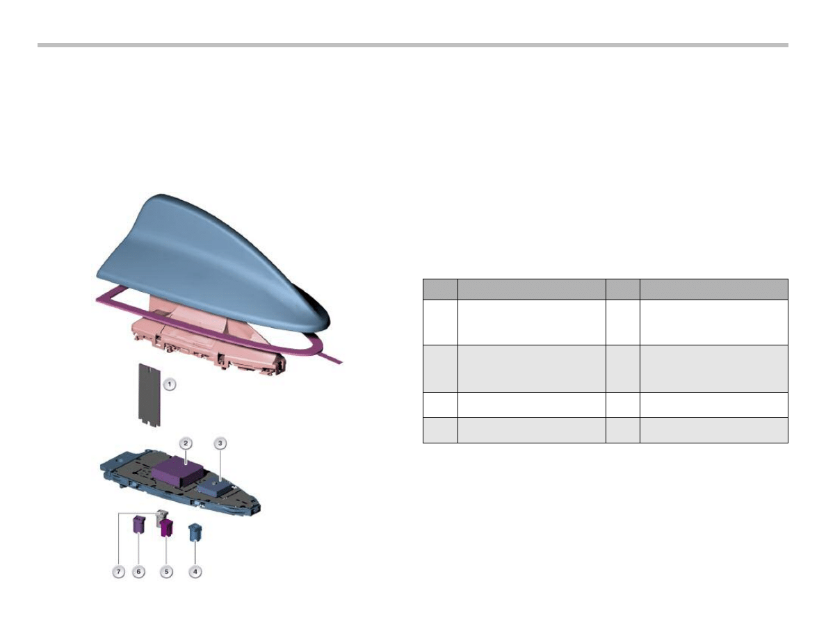
Roof Antenna
• Mobile phone antenna
• Telematics Control Unit (TCU) telephone antenna
• GPS antennal
• SDARS satellite reception antenna.
The SDARS system uses three satellites which follow an elliptical
orbit around the Earth. Because of the arrangement of the orbits,
there are always two satellites over the reception area.In areas with-
out coverage, the SDARS signals are beamed terrestrially. Both
SDARS signals (satellite and terrestrial) are received by an antenna
patch in the roof antenna and made available to the SDARS control
module.
Note: The antenna input to SDARS uses only one connec-
tion for the Satellite and the Terrestrial antenna.
Index
Explanation
Index
Explanation
1
Telephone antennas for mobile
phone and Telematics Control Unit
(TCU)
5
SDARS signal, satellite and
terrestrial connector color
code: pink
2
SDARS antenna for satellite
reception
6
Telephone signal: connector color
code: Bordeaux violet
3
GPS antenna
7
Telephone signal: connector color
code: Grey
4
GPS signal connector color code:
blue

E70 Audio Systems Workbook
17
What are the four functions of the favorites buttons? Match the action on the left column with the proper function on the right column.
Brief touching of the button
Programs button
Touching of the button (>3 sec.)
Selects the programmed feature
Pressing of the button
Calls up a detailed menu on the CID on how buttons are programmed
Pressing and holding the button down
Calls up a brief menu on the CID on how buttons are programmed
Which functions can be stored as one of the favorites buttons?
q Climate control function
q FM radio
q AM radio
q Sirius Digital Radio
q Weather band
q CD Track on CD placed in CD drive
q CD of CD Changer
q DVD drive
q Lighting setting
q Navigation destination
q Telephone number
Activate the fast load function to insert multiple CDs in the CD Changer. (Note the LED status of the CD Changer.)
Workshop Exercise - Favorites Button
Operate the favorites buttons and the CD changer and fill out the information below.
18
E70 Audio Systems Workbook
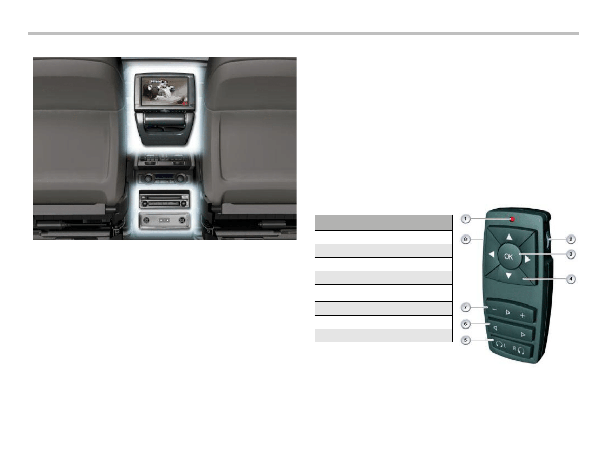
Rear Seat Entertainment (RSE)
A rear entertainment system" Rear DVD system" is offered as an
option in the new BMW X5 (E70).The system consists of the fol-
lowing components:
• Rear Seat Entertainment (RSE) control module
• 8" color monitor with folding mechanism and infrared
transmitter
• Headphone connection
• Remote control.
The "DVD system in the rear" offers the following functions:
• Playback of photos, audio or video
• Connection to external equipment
• Headphone connection.
The rear seat entertainment is functionally independent of the
other entertainment sources available in the vehicle. Via the iDrive,
the driver or front passenger can release or lock the rear seat enter-
tainment in the "Settings" menu. The rear seat entertainment pro-
gram cannot be controlled by iDrive.
Once the rear seat entertainment system is activated, the rear-seat
passengers can be entertained by the rear display and headphones
or audio speakers in the vehicle. If headphones are used, a different
medium can be enjoyed via the rear seat entertainment system,
independently from the vehicle audio system. The rear seat enter-
tainment display or headphones can be controlled by a remote
control. The settings made are displayed in the rear display. No
visual status signal display is issued for volume navigation.
Index
Explanation
1
Function LED
2
Thumbwheel
3
Confirmation button
4
Cross-control key (four buttons)
5
wired headphones eft/right
6
Station/track search
7
Wired headphones volume
8
Start menu
E70 Audio Systems Workbook
19
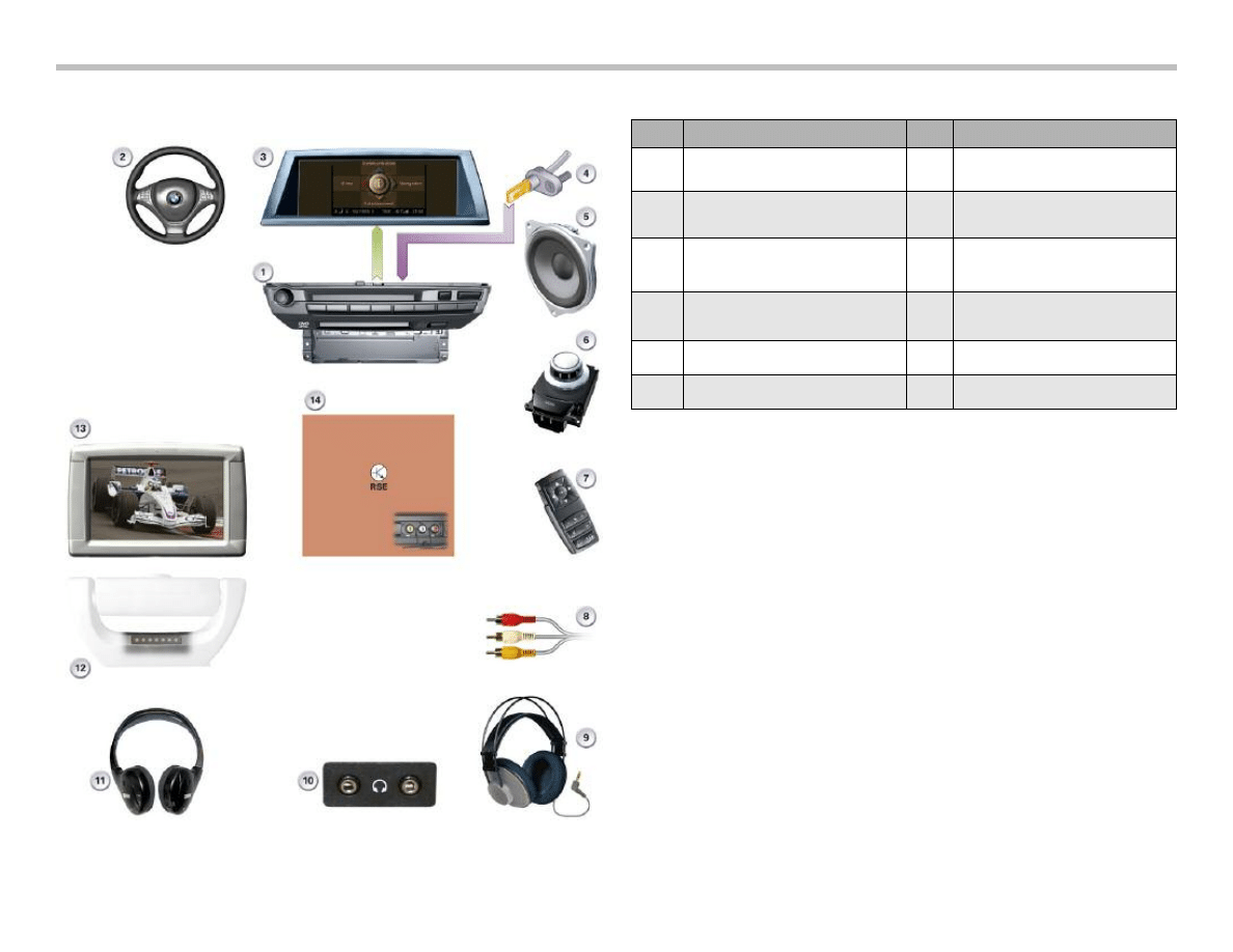
Rear Seat Entertainment
Index
Explanation
Index
Explanation
1
Car Communication Computer
(CCC)
8
Connection to external equipment
2
Multifunction steering wheel (MFL)
9
Wired headphones(no equipment
specification)
3
Central information display (CID)
10
Headphone sockets for wired head-
phones
4
Wheel speed sensor
11
Infrared headphones
(no equipment specification)
6
Controller
13
Rear seat area display
7
Remote control
14
RSE control module
Initializing the Remote Control
There is a test plan for teaching-in the remote control in the diag-
nostics under “Rear Seat Entertainment.”
The test plan works through the following steps:
• The entry of the current detected remote control for the rear
seat entertainment is deleted in CAS3.
• The remote control for the rear seat entertainment is initial-
ized.
• Successful initialization of the remote control is acknowledged
by the automatic closing and opening of the central locking.
Note: Remote controls are not interchangeable. Only the
initialized remote control is functional in the vehicle.
20
E70 Audio Systems Workbook
R
e
ar
S
e
at
E
n
te
rt
ain
m
e
n
t
S
y
st
e
m
C
irc
u
it
D
ia
g
ra
m

E70 Audio Systems Workbook
21
In
d
ex
E
xp
la
n
at
io
n
In
d
ex
E
xp
la
n
at
io
n
1
H
ea
ds
et
1
3
R
em
ot
e c
on
tro
l
2
C
en
tra
l in
fo
rm
ati
on
d
is
pla
y
1
4
R
em
ot
e c
on
tro
l s
er
vic
es
a
er
ia
l
3
C
on
tro
lle
r
1
5
A
er
ia
l a
m
pli
fie
rw
ith
d
ive
rs
ity
m
od
ule
4
B
ro
ad
ba
nd
s
pe
ak
er
rig
ht-
ha
nd
fro
nt
do
or
1
6
R
ea
rs
ea
te
nt
er
ta
in
m
en
t
5
C
en
tra
l b
as
s s
pe
ak
er,
rig
ht
1
7
In
fra
re
d t
ra
ns
m
itte
r
6
R
ea
rs
ea
ta
re
a d
is
pla
y
1
8
In
fra
re
d h
ea
dp
ho
ne
s
7
W
ire
d h
ea
dp
ho
ne
s,
le
ft
1
9
B
ro
ad
ba
nd
s
pe
ak
er
le
ft-
ha
nd
re
ar
do
or
8
W
ire
d h
ea
dp
ho
ne
s,
rig
ht
2
0
C
ar
A
cc
es
s S
ys
te
m
3
9
B
ro
ad
ba
nd
s
pe
ak
er
rig
ht-
ha
nd
re
ar
do
or
2
1
C
en
tra
l b
as
s s
pe
ak
er,
le
ft
1
0
H
ea
dp
ho
ne
s
oc
ke
t, r
ig
ht
2
2
A
ud
io
ja
ck
1
1
H
ea
dp
ho
ne
s
oc
ke
t, l
eft
2
3
B
ro
ad
ba
nd
s
pe
ak
er
le
ft-
ha
nd
fro
nt
do
or
1
2
A
V
in
pu
t(e
xte
rn
al
eq
uip
m
en
t)
A
U
X
_N
F
_L
A
ud
io
in
pu
tfo
ra
dd
itio
na
l a
ud
io
s
ou
rc
es
,
le
ft-
ha
nd
c
ha
nn
el
A
U
X
_N
F
_R
A
ud
io
in
pu
tfo
ra
dd
itio
na
l a
ud
io
s
ou
rc
es
,
rig
ht
ha
nd
c
ha
nn
el
F
B
D
R
em
ot
e c
on
tro
l s
er
vic
es
IR
_F
S
P
P
ow
er
su
pp
ly
in
fra
re
d t
ra
ns
m
itte
r
IR
_G
N
D
In
fra
re
d t
ra
ns
m
itte
r, g
ro
un
d
IR
_S
IG
N
A
L
In
fra
re
d t
ra
ns
m
itte
rs
ig
na
l
K
H
1
_L
Le
ft-
ha
nd
h
ea
dp
ho
ne
s,
le
ft
ha
nd
c
ha
nn
el-
K
H
1
_R
Le
ft-
ha
nd
h
ea
dp
ho
ne
s,
rig
ht
ha
nd
c
ha
nn
el
K
H
2
_L
R
ig
ht-
ha
nd
h
ea
dp
ho
ne
s,
le
ft-
ha
nd
c
ha
nn
el
K
H
2
_R
R
ig
ht-
ha
nd
h
ea
dp
ho
ne
s,
rig
ht-
ha
nd
c
ha
nn
el
LV
D
S
_
Lo
w
vo
lta
ge
d
iffe
re
nt
ia
l s
ig
na
l
(d
ig
ita
l R
G
B
s
ig
na
l)
M
O
S
T
M
ed
ia
O
rie
nta
te
d S
ys
te
m
T
ra
ns
po
rt
(d
ig
ita
l b
us
)
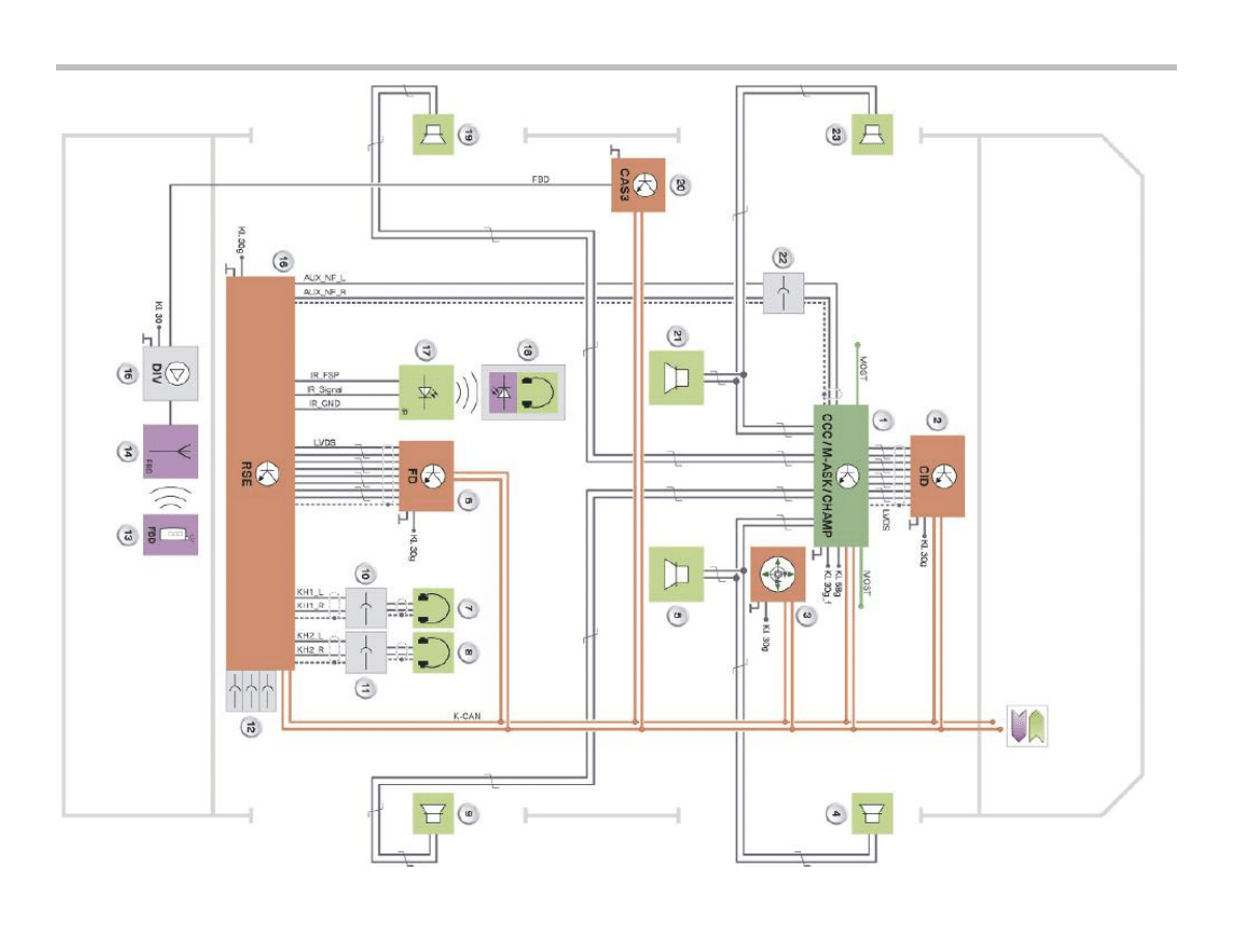
R
e
ar
S
e
at
E
n
te
rt
ain
m
e
n
t
S
y
st
e
m
C
irc
u
it
D
ia
g
ra
m
L
e
g
e
n
d

22
E70 Audio Systems Workbook
Note: Audio is played back either through the audio speak-
ers in the vehicle or via the headphones. The road
speed dependent volume control will only affect the
audio playback through the speakers and not the
headphones
The commands entered using the remote control of the rear seat
entertainment are transferred via the transmission frequency, which
is also used for the radio remote control key function.
The frequency used is dependent on the national variant and there-
fore relevant for coding. and therefore relevant for coding.
The commands are received by the FBD aerial and routed via the
antenna amplifier with diversity module to the CAS3. The CAS3
converts the signals into K-CAN messages. The commands then
reach the RSE control module via the K-CAN.
If audio is played back via the audio speakers in the vehicle, the
audio signal is routed from the RSE control module via the
AUX_NF cables and via the audio socket to the radio or navigation
system Aux_In. The audio socket is standard equipment in the E70
and fitted under the center armrest. The connection to the RSE
control module is disconnected manually by connection of an
external item of equipment to the audio socket.
Other external items of equipment can be connected via the AV
input to the RSE control module.
The programming, coding and diagnostics for the rear seat enter-
tainment are performed via the K-CAN. The terminal status is also
transferred as a K-CAN message.
The wheel speed signals are routed from the DSC control module
to the PT-CAN and converted in the Junction-box ECU (JB) to the
K-CAN protocol. The instrument cluster processes the road-speed
signal and makes it available on the K-CAN.
Navigation Systems
Map navigation (Professional navigation system) based on the Car
Communication Computer (CCC) is provided in the E70. The func-
tions correspond with the areas already known in the E60, E61,
E63, E64, E90, E91 and E92.
Via the voice input, the CCC supports the entry of whole words for
a country, town and street. It is still also possible to spell the desti-
nation.
For the market launch of the E70 in the USA, the (RTTI) traffic
warning system (Real Time Traffic Information) is provided. The
service is controlled by the "Traffic information for navigation"option
and is currently included in the range of functions of the
"Professional navigation system" option.
RTTI is transferred in the form of a data stream from particular FM
stations. The data is received from the CCC FM tuner, evaluated
and made available for the navigation system. In the navigation
map, traffic issues are indicated by symbols. The traffic issues are
also available in a list. The list entries are then sorted by the current
distance between the vehicle and the traffic issue. If the traffic issue
is on the current route, there is a voice output.

E70 Audio Systems Workbook
23
How is the RSE remote control “initialized”?
How can the following be changed on the FD?
(check the correct answer)
Date
q iDrive
q RSE
Time
q iDrive
q RSE
Language
q iDrive
q RSE
Is it possible to have media that is inserted into the Rear Seat
Entertainment module played via the vehicle speakers?
q Yes
q No
Look up the Wiring Diagram of the AUX input jack.
How is the audio routed between the RSE and the head unit?
Insert an appropriate plug into the AUX jack in the center console.
How does this affect the audio output of the RSE?
Where are the volume controls for:
Audio output via vehicle speakers:
Audio output via IR headphones:
Audio output via cable bound headphones:
Workshop Exercise - Rear Seat Entertainment
Operate the Rear Seat Entertainment
24
E70 Audio Systems Workbook
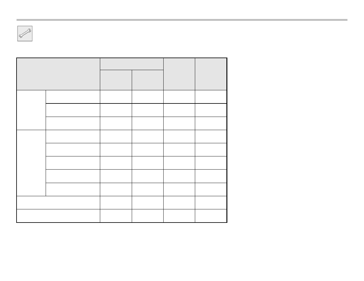
Workshop Exercise - Media Types
Utilize the media handed out by the instructor and note which media types are compatible for each control module (player).
CCC
CD
Changer
RSE
CD
Drive
DVD
Drive
D
V
D
Region 1
Region (other)
NTSC
C
D
Audio
mp3
m4a/AAC
wma
photo
Other
Other
Document Outline
- Main Menu
- E70 Introduction
- E70 Powertrain
- E70 Voltage Supply and Bus Systems
- E70 Chassis Dynamics
- E70 General Vehicle Electronics
- E70 Head-Up Display
- E70 Audio Systems
- E70 Climate Control
- E70 Passive Safety
Wyszukiwarka
Podobne podstrony:
16 E70 Audio Systems
07b E70 Audio Systems
07 emission control system
wykład 07 zeszły rok systemy szkolne - Malta, studia, andragogika
Navigation and Audio System
07 Teoria prawa SYSTEM PRAWA
07 Metodyka wdrożenia systemu hurtowni danych
diagnostics Audio System
Audio System for Built In Type Amplifier
Audio System for Separate Type Amplifier
07 emission control system
93ZJ Secc 8F Audio Systems
09 E65 Audio System
08 E70 Climate Control WB
04a E65 Audio System
96ZJ 8F AUDIO SYSTEMS
więcej podobnych podstron