
Initial Print Date: 10/06
Table of Contents
Subject
Page
Audio Systems in the New BMW X5 . . . . . . . . . . . . . . . . . . . . . . . . . . . . . .3
Professional Radio (CHAMP) . . . . . . . . . . . . . . . . . . . . . . . . . . . . . . . . . . .19
Amplifiers and Speakers . . . . . . . . . . . . . . . . . . . . . . . . . . . . . . . . . . . . . . .22
HiFi System . . . . . . . . . . . . . . . . . . . . . . . . . . . . . . . . . . . . . . . . . . . . . . . . . .23
Top-HiFi System . . . . . . . . . . . . . . . . . . . . . . . . . . . . . . . . . . . . . . . . . . . . . .24
Top-HiFi Amplifier . . . . . . . . . . . . . . . . . . . . . . . . . . . . . . . . . . . . . . . . . . . . .25
IKT Antennas . . . . . . . . . . . . . . . . . . . . . . . . . . . . . . . . . . . . . . . . . . . . . . . . .26
Blocking Circuit and HBL Filter . . . . . . . . . . . . . . . . . . . . . . . . . . . . . . .28
Roof Antenna . . . . . . . . . . . . . . . . . . . . . . . . . . . . . . . . . . . . . . . . . . . . . . .30
Radio Antennas . . . . . . . . . . . . . . . . . . . . . . . . . . . . . . . . . . . . . . . . . . . . .31
FM Antenna Diversity . . . . . . . . . . . . . . . . . . . . . . . . . . . . . . . . . . . . . . .32
Digital Tuners . . . . . . . . . . . . . . . . . . . . . . . . . . . . . . . . . . . . . . . . . . . . . . . . .33
CD Changer . . . . . . . . . . . . . . . . . . . . . . . . . . . . . . . . . . . . . . . . . . . . . . . . . .35
Retrofitting a CD Changer . . . . . . . . . . . . . . . . . . . . . . . . . . . . . . . . . . .38
Reset . . . . . . . . . . . . . . . . . . . . . . . . . . . . . . . . . . . . . . . . . . . . . . . . . . . . . .40
Service Concept . . . . . . . . . . . . . . . . . . . . . . . . . . . . . . . . . . . . . . . . . . . .40
HiFi Amplifier . . . . . . . . . . . . . . . . . . . . . . . . . . . . . . . . . . . . . . . . . . . . . . .40
Top-HiFi Amplifier . . . . . . . . . . . . . . . . . . . . . . . . . . . . . . . . . . . . . . . . . .41
Antenna Diagnosis . . . . . . . . . . . . . . . . . . . . . . . . . . . . . . . . . . . . . . . . . .41
Service Mode . . . . . . . . . . . . . . . . . . . . . . . . . . . . . . . . . . . . . . . . . . .41
Hissing or Interference on Radio . . . . . . . . . . . . . . . . . . . . . . . . . . .42
E70 Audio Systems
Revision Date:

2
E70 Audio Systems
Audio Systems
Model: E70
Production: From Start of Production
After completion of this module you will be able to:
• Identify the Audio Systems Used on the E70.
• Describe the different functions of the two Audio Systems of the E70
• Identify the components integrated to the Audio Systems on the E70.
Audio Systems in the New BMW X5
The following audio equipment is available in the new BMW X5 (E70):
• Professional radio
• Professional navigation system.
The Professional radio is standard equipment. The standard equipment comprises the
iDrive with controller and Central Information Display (CID). US vehicles are equipped
with CHAMP (Central Head unit and Multimedia Platform), the new platform for the mid-
range radio segment in BMW vehicles.
An enhancement of the CCC (Car Communication Computer) is available as the Head
unit for the Professional navigation system.
The Professional radio and Professional navigation system offer eight favorites buttons.
There are six favorites buttons that can be assigned favorites while the other two are
assigned fixed functions.
CHAMP Favorites Buttons
The radio and navigation system can be combined with the following speaker and ampli-
fier systems:
• HiFi system
• Top-HiFi system.
The Professional radio with HiFi system is standard equipment on US vehicles.
The Top-HiFi system is available as option "Professional HiFi system".
Digital radio is available in addition to AM and FM stations, the SDARS satellite tuner will
be available from market launch. High definition radio will be available at a later date.
Note: A single-slot CD changer is available in a BMW for the first time. This
changer holds six discs, which are inserted into the unit without the use
of a magazine.
3
E70 Audio Systems
Introduction

E70 Audio Systems
The HiFi system has five tweeters, five mid-range speakers and two central bass speak-
ers. The HiFi amplifier has a K-CAN connection for diagnostics and coding.
The Top-HiFi system has seven tweeters, seven mid-range speakers and two central
bass speakers. The Top-HiFi amplifier is connected to the MOST.
The following pages show the input/output diagrams and system circuit diagrams for the
audio systems of the E70:
• Amplifier and speaker systems
• Digital tuners.
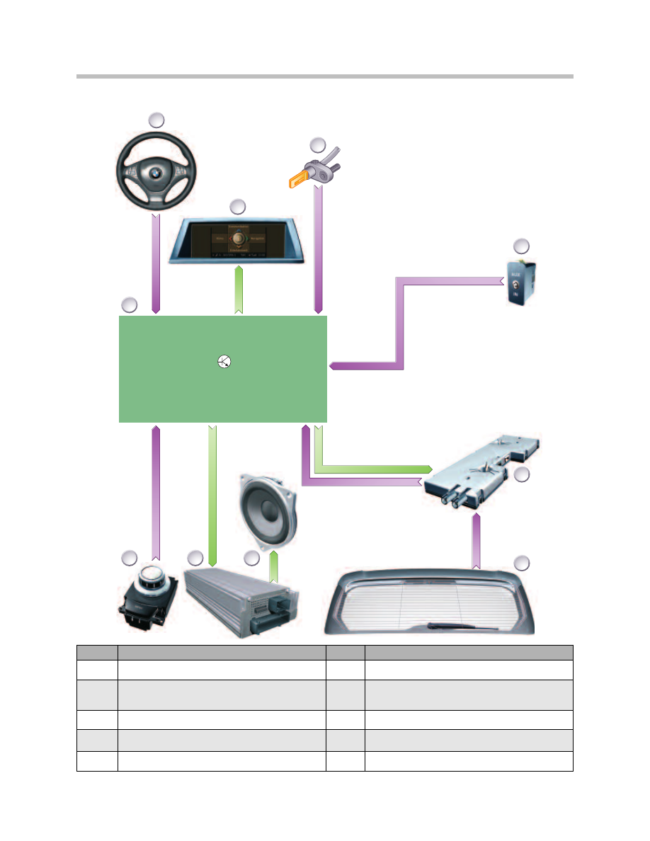
The input/output diagram shows the subscribing control units, sensors, controls and
components. For emphasis, only the control unit concerned is shown in its block repre-
sentation. The input/ output diagram gives an overview of the system concerned, repre-
sented as a signal path. It does not show whether the signals are sent via bus connec-
tions, additional control units, by fixed wire or by wireless. This detailed information is
contained in the system circuit diagram
The input/output diagram also applies to the HiFi system, if the HiFi amplifier were
shown in place of the Top-HiFi amplifier.
The wheel speed signals are sent from the DSC control unit on the PT-CAN and con-
verted to the K-CAN protocol in the Junction-box ECU (JB). The instrument cluster
processes the speed signal and outputs this on the K-CAN.
The differences between the HiFi system and the Top-HiFi system are illustrated in the
following system circuit diagrams.
4
E70 Audio Systems
System Overview
CCC / CHAMP
TE
06
-1
12
3
2
1
4
5
8
9
10
3
6
7
5
E70 Audio Systems
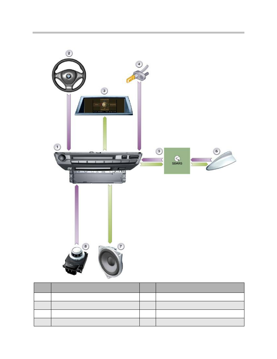
HiFi System and Top-HiFi System Input/output Diagram
Index
Explanation
Index
Explanation
1
Head unit (CCC or CHAMP)
6
Antenna amplifier with diversity module
2
Multifunction steering wheel (MFL)
7
Rear spoiler (FM1, AM) and rear window anten-
nas (FM2, FM3)
3
Central information display (CID)
8
Audio speaker
4
Wheel speed sensor
9
Top-HiFi amplifier
5
Audio jack
10
Controller
Aux_NF_GND
Aux_NF_L
Aux_NF_R
LVDS
Kl. 30g_f
Kl. 58g
Kl. 30g
CID
Kl. 30g
Kl. 30g
CDC
HIFI
K
-C
A
N
M
O
S
T
DIV
2x
FM
FM
AM
HF+ZF+U
S
Rad_on
FS
Rad_on
CCC / CHAMP
3
4
5
2
23
9
8
25
26
21
22
7
6
11
20
10
14
13
12
15
24
1
6
E70 Audio Systems
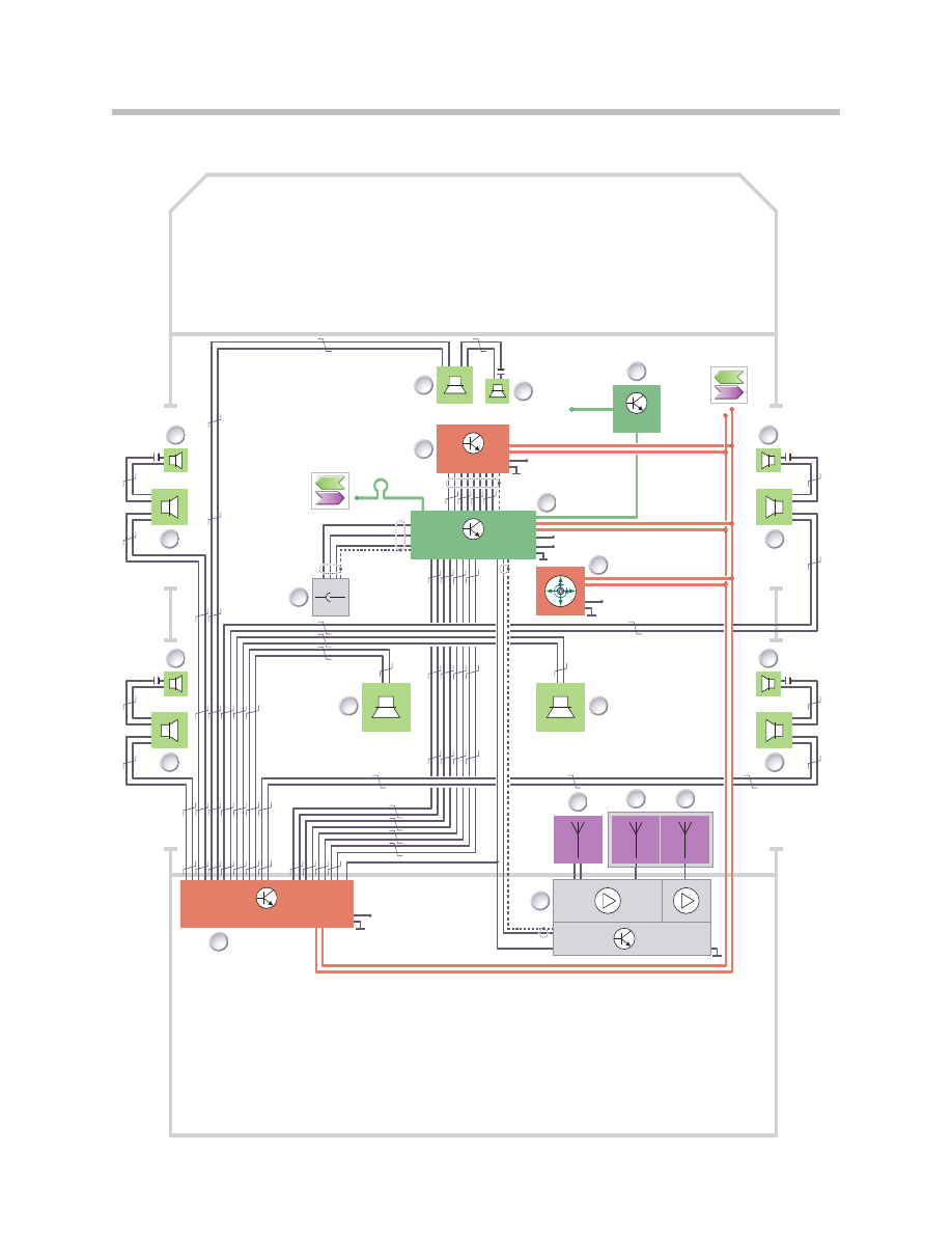
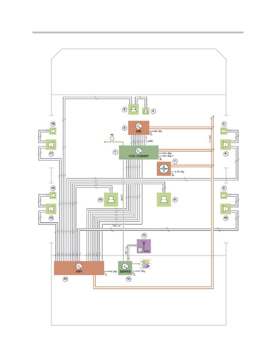
HiFi System Circuit Diagram

7
E70 Audio Systems
Legend for HiFi System Circuit Diagram
Index
Explanation
Index
Explanation
1
Head unit
12
Rear spoiler antenna (AM)
2
Central information display
13
Rear spoiler antenna (FM1)
3
Mid-range speaker, front center
14
Rear window antennas (FM2, FM3)
4
Tweeter, front center
15
Antenna amplifier with diversity module
5
CD changer
20
HiFi amplifier
6
Tweeter, front right door
21
Mid-range speaker,rear left door
7
Mid-range speaker, front right door
22
Tweeter, rear left door
8
Controller
23
Central bass speaker, left
9
Central bass speaker, right
24
Audio jack
10
Tweeter,rear right door
25
Mid-range speaker, front left door
11
Mid-range speaker, rear right door
26
Tweeter, front left door
LVDS
Low voltage differential signal
MOST
Media Oriented System Transport (digital bus)
Aux_NF
Audio input for additional audio sources
FS
MOST direct access
Rad_On
Control signal or power supply
US
Switching voltage
HF
High frequency signal
ZF
Intermediate frequency signal

K-CAN signals at the CCC/CHAMP control unit
MOST signals at the CCC/CHAMP control unit
The HiFi amplifier is connected to the K-CAN for coding and diagnostics. There is no
facility provided for programming the HiFi amplifier.
The HiFi amplifier is woken by the Rad_On signal sent by fixed wire from the Head unit.
The tweeters and mid-range speakers are connected in parallel. The capacitors at the
tweeters act as duplexers and, in the case of the HiFi system, are electrolytic.
The CHAMP receives the terminal 58g (lighting) signal by fixed wire. The CCC receives it
via the K-CAN.
8
E70 Audio Systems
In/out
Signal
Source/sink
Function
In
Speed signal
> Wheel speed sensor r
> DSC -JB - Kombi
Speed-dependent volume control
In
Button stroke
> Steering wheel buttons >
SZL
Volume, station selection
In
Terminal status
> START/STOP button
> CAS
Switch-on conditions
In (CCC
only)
Terminal 58g
> Photo diode
> FRM
Lighting
In/out
Signal
Source/sink
Function
In
Decoded audio signals
> CD > CD changer
Audio playback
In
Control signals
>CD changer
ID3 tags, CD content
In/out
Control signals
>CD changer
CD selection, track selection,terminal
control

9
E70 Audio Systems
NOTES
PAGE
10
E70 Audio Systems
Aux_NF_GND
Aux_NF_L
Aux_NF_R
LVDS
Kl. 30g_f
Kl. 58g
Kl. 30g
M
O
S
T
CID
CCC / CHAMP
Kl. 30g
Kl. 30g
CDC
MOST
TOP-HIFI
K
-C
A
N
M
O
S
T
DIV
2x
FM
FM
AM
HF+ZF+U
S
Rad_on
FS
3
4
5
2
23
9
8
25
26
21
22
7
6
11
16
17
19
20
18
10
14
13
12
15
24
1
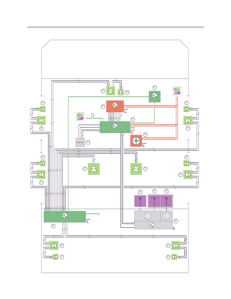
Top-HiFi System Circuit Diagram

11
E70 Audio Systems
Index
Explanation
Index
Explanation
1
Head unit
14
Rear window antennas (FM2, FM3)
2
Central information display
15
Antenna amplifier with diversity module
3
Mid-range speaker, front center
16
Mid-range speaker, D-pillar right
4
Tweeter, front center
17
Tweeter, D-pillar right
5
CD changer
18
Tweeter, D-pillar left
6
Tweeter, front right door
19
Mid-range speaker, D-pillar left
7
Mid-range speaker, front right door
20
Top-HiFi amplifier
8
Controller
21
Mid-range speaker, rear left door
9
Central bass speaker, right
22
Tweeter, rear left door
10
Tweeter, rear right door
23
Central bass speaker, left
11
Mid-range speaker, rear right door
24
Audio jack
12
Rear spoiler antenna (AM)
25
Mid-range speaker, front left door
13
Rear spoiler antenna (FM1)
26
Tweeter, front left door
LVDS
Low voltage differential signal
MOST
Media Oriented System Transport (digital bus)
Aux_NF
Audio input for additional audio sources
FS
MOST direct access
Rad_On
Control signal or power supply
US
Switching voltage
HF
High frequency signal
ZF
Intermediate frequency signal
Legend for Top HiFi System Circuit Diagram

12
E70 Audio Systems
K-CAN signals at the CCC/CHAMP control unit
MOST signals at the CCC/CHAMP control unit
The Top-HiFi amplifier is connected to the MOST for programming, coding and diagnos-
tics. The tweeters and mid-range speakers are connected in parallel. The capacitors at
the tweeters act as duplexers and, in the case of the Top-HiFi system, are high-quality foil
capacitors. The CHAMP receives the terminal 58g (lighting) signal by fixed wire. The CCC
receives it via the K-CAN.
In/out
Signal
Source/sink
Function
In
Speed signal
> Wheel speed sensor r
> DSC -JB - Kombi
Speed-dependent volume control
In
Button stroke
> Steering wheel buttons >
SZL
Volume, station selection
In
Terminal status
> START/STOP button
> CAS
Switch-on conditions
In (CCC
only)
Terminal 58g
> Photo diode
> FRM
Lighting
In/out
Signal
Source/sink
Function
In
Decoded audio signals
> CD > CD changer
Audio playback
In
Control signals
>CD changer
ID3 tags, CD content
In/out
Control signals
>CD changer
CD selection, track selection, terminal
control
Out
Audio signals
> Top-HiFi > audio speakers
Audio signals
Out
Control signals
>Top-HiFi
Speed-dependent volume control and
equalizer, terminal control
Out
Rad_On
>Top-HiFi
ON/OFF
13
E70 Audio Systems
Satellite Tuner (SDARS) Input/output Diagram
Index
Explanation
Index
Explanation
1
Head unit (CCC)
5
Satellite tuner (SDARS)
2
Multifunction steering wheel (MFL)
6
Roof antenna (SDARS)
3
Central information display (CID)
7
Audio speaker
4
Wheel speed sensor
8
Controller

The input/output diagram also applies to the CHAMP. The roof antenna receives SDARS
signals transmitted by satellite. The signals are amplified by an amplifier integrated in the
roof antenna and forwarded to the SDARS control module. The antenna amplifier is sup-
plied with power from the SDARS control module.
The SDARS control module decodes the digital audio signals and sends these to the
Head unit on the MOST. The Head unit converts the audio data into analogue LF signals.
The LF signals are output through the speakers.
Note: That SDARS is operated using the iDrive and information such as track
title, artist or album title are output in the CID.
14
E70 Audio Systems

15
E70 Audio Systems
NOTES
PAGE
16
E70 Audio Systems
Satellite Tuner (SDARS) System Circuit Diagram

MOST signals at the SDARS control module
SDARS is also available in conjunction with the Top-HiFi system. CHAMP receives the
terminal 58g (lighting) signal by fixed wire. The CCC receives it via the K-CAN.
17
E70 Audio Systems
Legend for Satellite Tuner (SDARS) System Circuit Diagram
Index
Explanation
Index
Explanation
1
Head unit
10
Mid-range speaker, rear right door
2
Central information display
11
Roof antenna (SDARS)
3
Mid-range speaker, front center
12
SDARS control module
4
Tweeter, front center
13
HiFi amplifier
5
Tweeter, front right door
14
Central bass speaker, left
6
Mid-range speaker, front right door
15
Mid-range speaker, rear left door
7
Controller
16
Tweeter, rear left door
8
Central bass speaker, right
17
Mid-range speaker, front left door
9
Tweeter, rear right door
18
Tweeter, front left door,
MOST
Media Oriented System Transport (digital bus)
FS
MOST direct access
LVDS
Low voltage differential signal
UB
Power supply
Rad_On
Control signal or power supply
In/Out
Signal
Source
Function
Out
Decoded audio signals
> Head unit
Audio playback
In/out
Control signals
> Head unit
Station selection, station
identifier, terminal control

This section describes the audio systems in the E70.
It is divided into the following chapters:
• Head units
• Amplifiers and speakers
• Antennas
• Digital tuners
• Peripherals
The following Audio Systems are available for the E70:
• Professional radio
• Professional navigation system.
The US vehicles are equipped with the new head unit platform called CHAMP (Central
Head unit and Multimedia Platform) The CCC (Car Communication Computer) is avail-
able as the head unit for the Professional navigation system. The head units offer eight
favorites buttons.
The radio and navigation system with integrated audio function can be combined with
the following speaker and amplifier systems:
• HiFi system
• Top-HiFi system.
Professional radio with HiFi system is standard equipment in the US vehicles.The Top-
HiFi system is available as option."SIRIUS Satellite Radio" (SDARS) is also available as
option. The "high-definition radio" (IBOC) will be available at a later date.
A single-slot 6 CD changer is available in a BMW for the first time. This changer holds six
discs, which are inserted into the unit without the use of a magazine.
The CHAMP and CD changer support playback of MP3 and WMA files. The CCC sup-
ports playback of MP3 files.
18
E70 Audio Systems
System Components
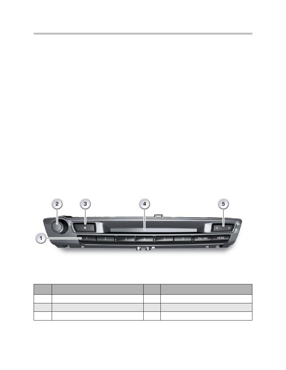
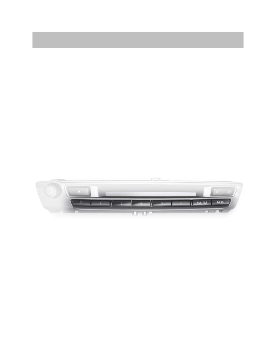
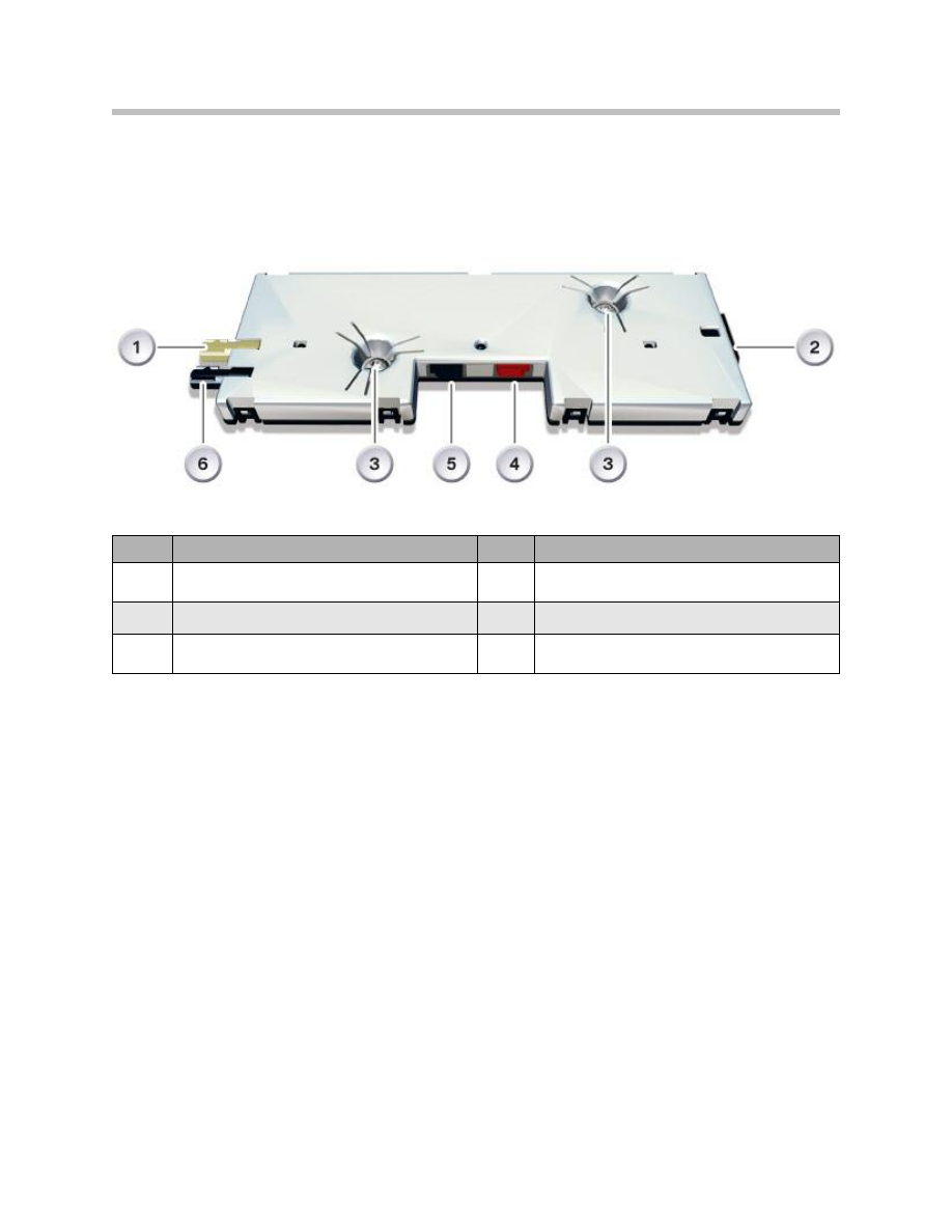
Professional Radio (CHAMP)
The CHAMP has six assignable favorites buttons. Button 7 is assigned with
FM/AM selection, button 8 is for toggling the operating mode.
CHAMP combines the following control modules in the one housing:
• RDS double tuner
• Audio system controller
• Gateway between MOST and K-CAN
• Interface to the Central Information Display.
CHAMPsystem can be used to control:
• Communication
• Entertainment
• Navigation
• Air conditioning (climate control)
• Settings (5th menu).
19
E70 Audio Systems
Index
Explanation
Index
Explanation
1
favorites buttons
4
CD drive slot
2
Rotary knob
5
Rocker switch for station selection/CD track skip
3
CD drive eject button
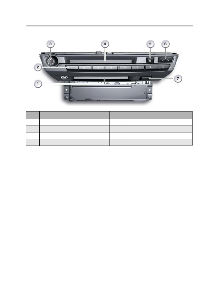
Professional Radio with NAV (CCC)
Note: Button 7 is assigned with FM/AM selection, button 8 is for toggling
the operating mode
The CCC combines the following control modules in one housing:
• Navigation computer/GPS module; map view and/or cursor view in the CID
• RDS double tuner
• Audio system controller (ASK)
• Gateway between MOST and K-CAN
• Interface to control display (LVDS).
Two drives are integrated in the housing:
• DVD player
• CD player
20
E70 Audio Systems
Index
Explanation
Index
Explanation
1
DVD drive slot
5
CD drive eject button
2
favorites buttons
6
Rocker switch for station selection/CD track skip
3
Rotary knob
7
DVD drive eject button
4
CD drive slot

When the navigation system is not in use, its DVD drive can be used to play audio CDs.
The playback of video files is not supported.
The CCC together with the controller and CID form the iDrive system.
The system can be used to control:
• Communication
• Entertainment
• Navigation
• Air conditioning (climate control)
• Settings (5th menu).
The MP3 directory structure corresponds to that of the PC. There is no limit to the num-
ber of directories, subdirectories and music tracks that the CCC can support. However,
the time taken for the drive to read the contents of the CD when the CD is inserted is
longer, depending on how much data is stored on the CD.
21
E70 Audio Systems
Amplifiers and Speakers
The speaker systems in the E70 are, as in other Series, available in two quality levels:
• HiFi system
• Top-HiFi system.
The HiFi system achieves double the power of the standard stereo system. In addition,
the HiFi system is equipped with a 7-channel amplifier with digital equalizer.
The optional Top-HiFi system achieves double the power of the standard HiFi system
and uses a digital 9-channel amplifier. Optimum audio playback in the vehicle is achieved
thanks to complex digital signal processing.
The HiFi system has twelve speakers while the Top- HiFi system has 16 speakers each
with different auxiliary amplifiers.
The central bass speakers are located under the front seats. They are coupled to the side
sills to increase the resonance volume necessary for bass reproduction.
The Professional radio and the Professional navigation system can be combined with any
of the amplifier/speaker systems, provided the specific national variants are taken into
consideration.
Note: The HiFi and Top-HiFi systems feature separate speakers for the treble
and midrange frequencies.
Even though the diameters of the speakers in the HiFi and Top-HiFi systems are the
same, there are differences in the power output of the speakers. This is achieved through
the use of different materials in the diaphragms, coils and magnets. The terms Medium
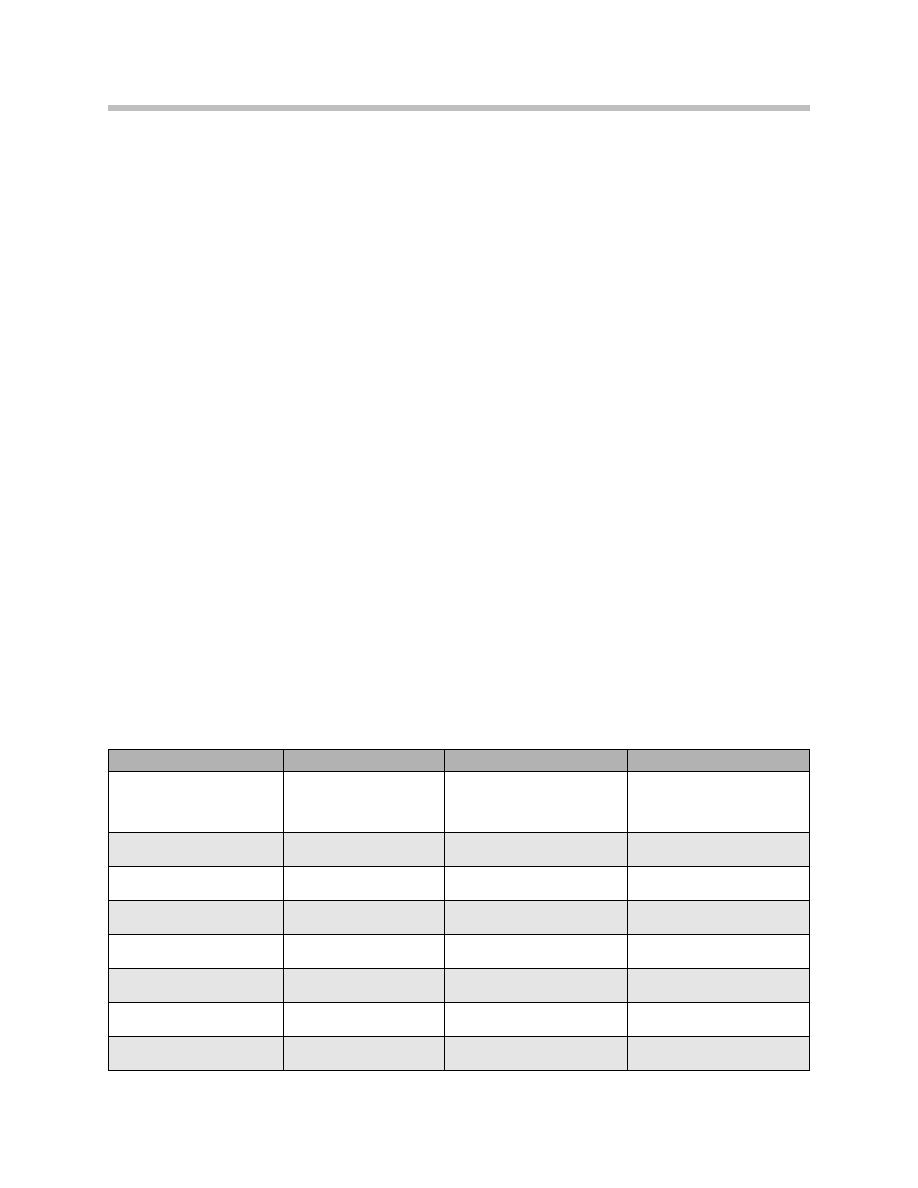
and High are used in the table below for distinction purposes.
22
E70 Audio Systems
Stereo system
HiFi system
Top-HiFi system
Output
CHAMP//CCC:
2°40 W (2
W) bass/
broadband 4°25 W (4
W)
Auxiliary amplifier:
2°40 W (2
W)
bass 5°25 W (4
W)
Auxiliary amplifier:
2°125 W (8
W)
bass 7°50 W (4
W)
Sound intensity
>98 dB as from 63 Hz
>104 dB as from
50 Hz
>110 dB as from
40 Hz
Bandwidth
40 Hz up to 15 kHz
30 Hz up to 20 kHz
20 Hz up to 20 kHz
Linearity
±4.5 dB
±3 dB
±1.5 dB
Tweeter
Manufacturer
26 mm (Medium) Phillips
26 mm (High)
Phillips
Broadband speaker
Manufacturer
100 mm
Phillips
Mid-range speaker
Manufacturer
100 mm (Medium) Phillips
100 mm (High)
Phillips
Woofer
Manufacturer
Phillips 160 mm
Phillips 217 mm
Phillips 217 mm
23
E70 Audio Systems
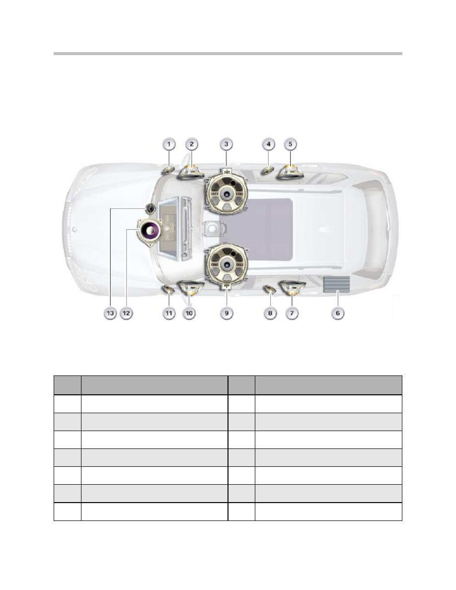
HiFi System
Index
Explanation
Index
Explanation
1
Tweeter, front right door
8
Tweeter ,rear left door
2
Mid-range speaker, front right door
9
Central bass speaker, left
3
Central bass speaker, right
10
Mid-range speaker, front left door
4
Tweeter, rear right door
11
Tweeter, front left door
5
Mid-range speaker ,rear right door
12
Mid-range speaker, front center
6
HiFi amplifier
13
Tweeter, front center
7
Mid-range speaker, rear left door
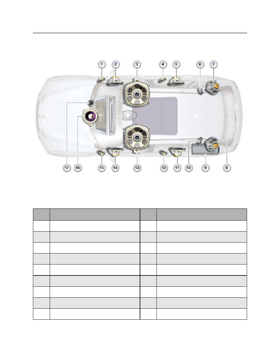
Top-HiFi System
24
E70 Audio Systems
Index
Explanation
Index
Explanation
1
Tweeter ,front right door
10
Tweeter ,D-pillar left
2
Mid-range speaker, front right door,
11
Mid-range speaker,rear left door
3
Central bass speaker, right
12
Tweeter, rear left door
4
Tweeter, rear right door
13
Central bass speaker, left
5
Mid-range speaker, rear right door
14
Mid-range speaker, front left door
6
Tweeter,D-pillar right
15
Tweeter, front left door
7
Mid-range speaker, D-pillar right
16
Mid-range speaker, front center
8
Mid-range speaker ,D-pillar left
17
Tweeter, front center
9
Top-HiFi amplifier
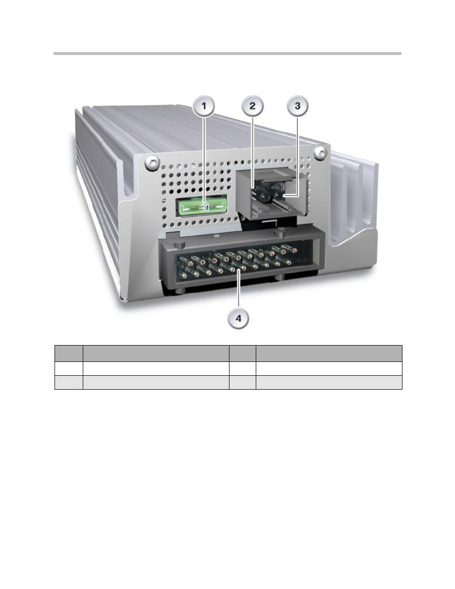
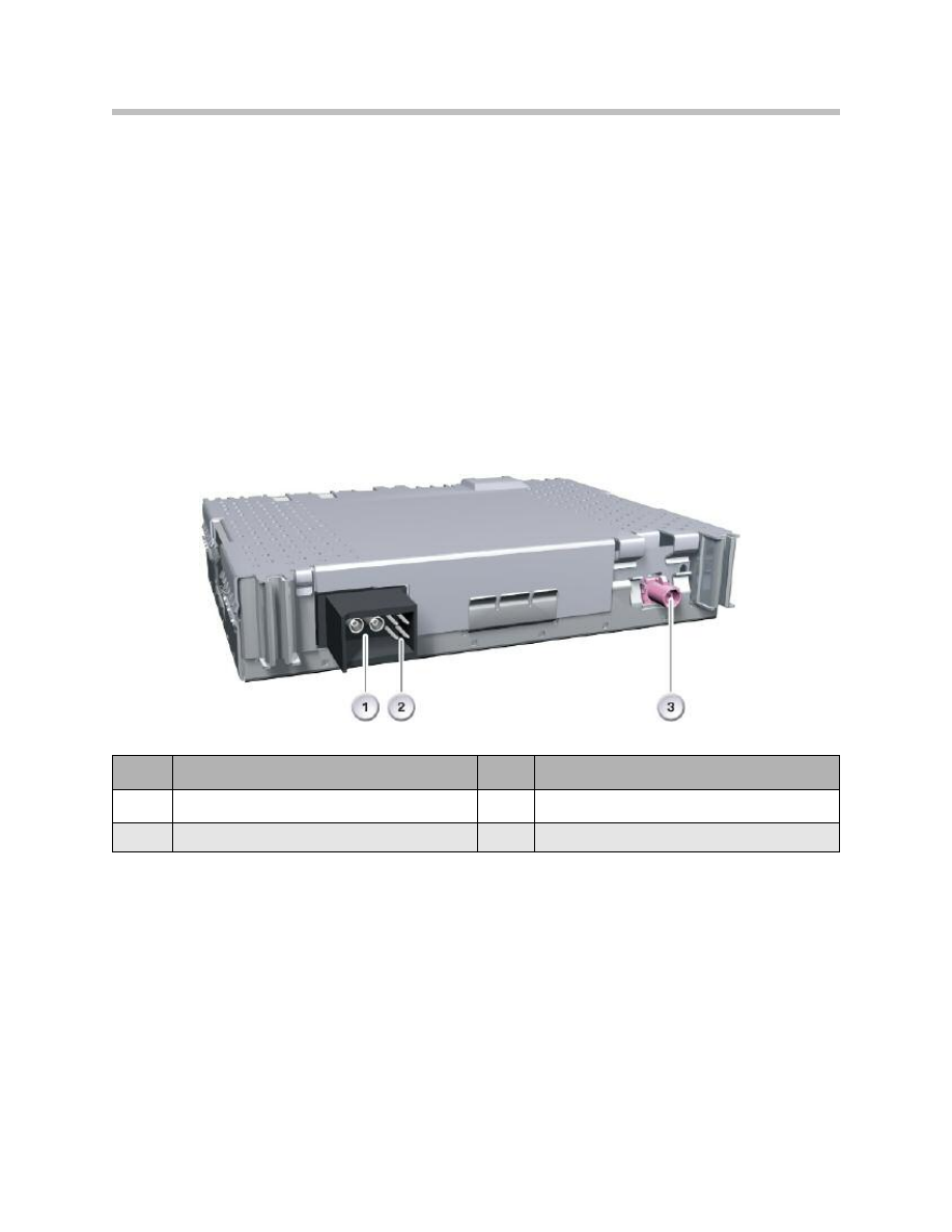
Top-HiFi Amplifier
The essential features of the Top-HiFi amplifier are:
• MOST control module
• 7-channel equalizer with control by iDrive
• Higher output power in the low frequency range
• 15 V output voltage for each mid-range speaker/tweeter
• 30 V output voltage for each central bass speaker.
The audio signals and the control signals are sent in digital form to the Top-HiFi amplifier
through the fiber-optic cable (MOST). Programming, coding and diagnostics are carried
out via the MOST.
25
E70 Audio Systems
Index
Explanation
Index
Explanation
1
Safety fuse
3
MOST
2
Power supply
4
Audio signals

To generate surround sound information from a stereo signal, the Top-HiFi amplifier in the
E70 supports Dolby Surround Pro Logic II.
This method replaces the Logic7 application from other BMW vehicles. This makes it
possible to generate a spatial sound pattern from the stereo signal that is only delivered
by the left and right channel.
The signals of the individual channels are output with time correction from the 16 avail-
able speakers of the Top-HiFi system in the E70. This achieves an homogenous sound
pattern for the listener in the 7.2 format.
Audio playback can also be adjusted by the customer using the 7-channel equalizer inte-
grated in the Top-HiFi amplifier. After signals have been processed, the audio signals are
forwarded as analogue low frequency (LF) signals to the speakers.
The Top-HiFi amplifier supports speed dependent equalization in addition to speed
dependent volume control. The effect is that the frequency response is adjusted in rela-
tion to the speed of the vehicle.
A total of 16 speakers are controlled through nine audio channels with Top-HiFi quality:
• one tweeter and mid-range speaker in each of the front doors
• one tweeter and mid-range speaker in the instrument panel
• one tweeter and mid-range speaker in each of the rear doors
• one tweeter and mid-range speaker in each of the D-pillars
• one central bass speaker under each of the front seats.
Note: The Top-HiFi amplifier is located in the rear left of the luggage
compartment behind the side panel trim.
IKT Antennas
The E70 has up to five antennas systems, depending on equipment options:
• FM/AM radio (spoiler and rear window Antennas)
• Digital tuners (roof antenna and left side window)
• Navigation system (roof antenna)
• Telephone (roof antenna) additionally:
– Bluetooth antenna under the center console for mobile phone connection
– Emergency antenna, rear left (only in conjunction with Telematics Control Unit TCU)
26
E70 Audio Systems
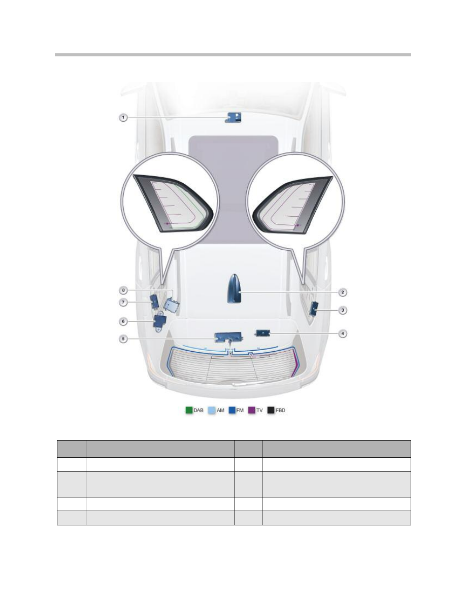
IKT Antennas
27
E70 Audio Systems
Index
Explanation
Index
Explanation
1
Bluetooth antenna
5
Antenna amplifier with diversity module
2
Roof antenna(navigation, telephone,
digital tuners)
6
SOS antenna
3
TV2 amplifier (not for U.S.)
7
TV1/DAB band III amplifier (not for U.S.)
4
TV3 amplifier (not for U.S.)
8
Blocking circuit and HBL filter
In addition to the antennas listed above are the Antennas for the remote control (FBD)
and the
nine Antennas for Comfort Access (four on the outside and five in the interior). You will
find further information in the "Central locking", "Comfort Access" and "Car Access
System" Product Information documentation.
The radio antennas for AM (waveband: LW, MW, KW) and FM (waveband: UHF) recep-
tion are described below.
The HBL filter is fitted to suppress interference pulses from the additional brake light dur-
ing radio reception. The same unit houses the capacitor of the rear window heater block-
ing circuit. The inductive resistor for the blocking circuit is located in the supply line of the
rear window heating.
Blocking Circuit and HBL Filter
28
E70 Audio Systems
Index
Explanation
Index
Explanation
1
Rear window heater, vehicle side
Connector color code: black
4
Securing screw with ground connection
2
HBL filter, vehicle side
Connector color code: black
5
HBL filter, rear window side
Connector color code: purple
3
Rear window heater, rear window
side Connector color code: white
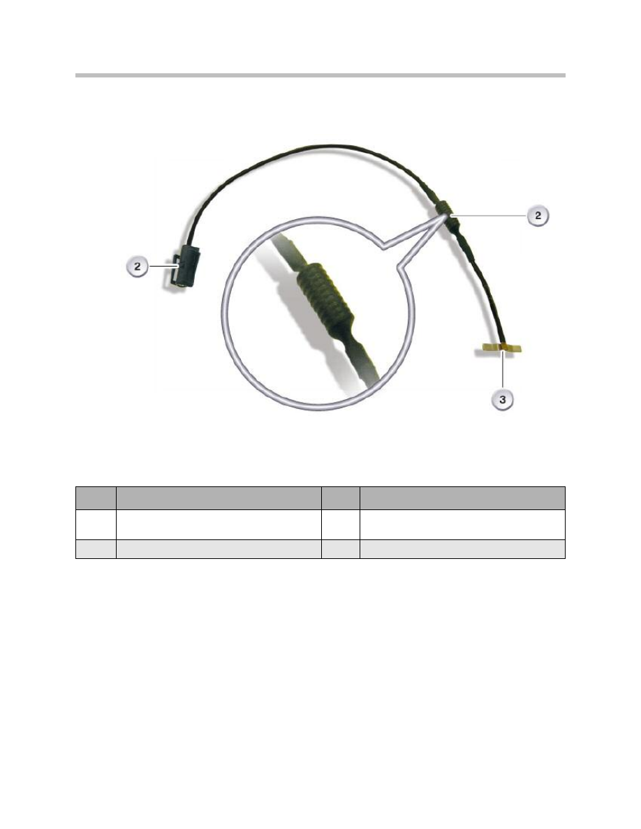
Rear Window Blocking Circuit Inductive Resistor
29
E70 Audio Systems
Index
Explanation
Index
Explanation
1
Inductive resistor
3
Connection, vehicle side Connector
color code: black
2
Rear window connection
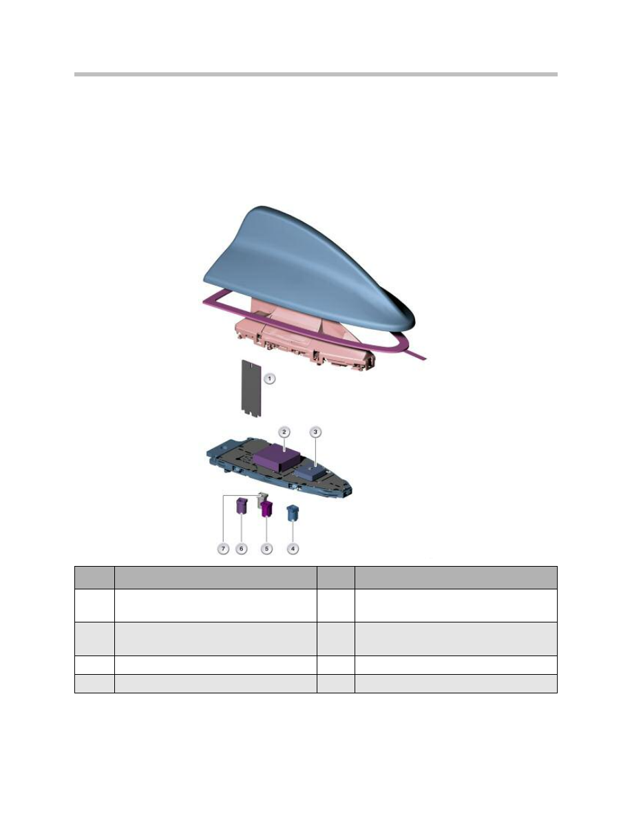
Roof Antenna
• Mobile phone antenna
• Telematics Control Unit (TCU) telephone antenna
• GPS antennal
• SDARS satellite reception antenna.
Note: The telephone antennas for the mobile phone and the TCU are on differ-
ent sides of the same circuit board.
30
E70 Audio Systems
Index
Explanation
Index
Explanation
1
Telephone antennas for mobile phone and
Telematics Control Unit (TCU)
5
SDARS signal, satellite and terrestrial
Connector color code: pink
2
SDARS antenna for satellite reception
6
Telephone signal:
connector color code: Bordeaux violet
3
GPS antenna
7
Telephone signal: connector color code: Grey
4
GPS signal connector color code: blue
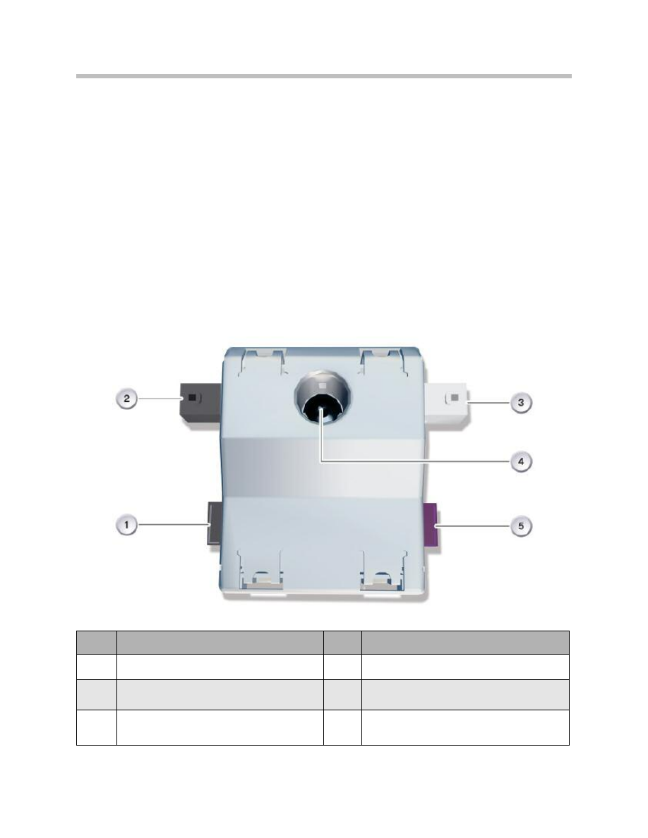
Radio Antennas
The high-frequency signals of the radio stations are received by the spoiler antenna
(AM and FM1) and the rear window antenna (FM2 and FM3).
Antenna Amplifier with Diversity Module
The assignment of the antenna amplifier with diversity module may differ depending on
the vehicle equipment. The TV3 signal is not currently used.
The antenna amplifiers for AM and FM are supplied with DC voltage from terminal
Rad_On when the radio is switched on. The high-frequency signals of the AM, FM1
antenna in the spoiler and of the FM2, FM3 antennas on the rear window are sent to the
antenna amplifier with diversity module by means of a ribbon cable.
Note: In US vehicles, the antenna amplifier also supports the frequencies of the
weather band. Weather band is transmitted over seven channels in the
frequency range from 162.400 MHz to 162.550 MHz.
Note: The antenna amplifiers are in the Diversity module. There are separate
amplifiers for AM and FM. The installation location is on the inside of
the tailgate above the rear window.
31
E70 Audio Systems
Index
Explanation
Index
Explanation
1
VICS signal (not for US)
4
Rear window antennas
(FM2, FM3, TV3)
2
Power supply and FBD
5
Spoiler antennas (AM, FM1)
3
Securing screw with
ground connection
6
AM/FM tuner signal
Connector color code: black

FM Antenna Diversity
In the E70, an FM antenna diversity is standard equipment.
The FM antennal diversity comprises:
• FM1, FM2 and FM3 antennas
• FM antenna amplifier with diversity module.
The sequence of the FM antenna diversity is defined as:
FM1 - FM2 - FM1 - FM3.
It then switches back to the FM1 antenna again.
The FM1 antenna has the best reception characteristics due to its location in the rear
spoiler. The defined sequence in which the antennas are switched ensures that the FM
antenna with the best reception characteristics has priority over the others.
For SW, MW and LW reception, no antenna diversity system is provided as there is only
one AM antenna available.
The signal quality of the currently selected FM antenna (FM1 to FM3) is evaluated in the
diversity module. The antenna diversity module will switch to the next FM antenna if the
signal quality of the current radio station on the active antenna deteriorates to a certain
level in terms of quality and field strength.
The switching takes place such manner that no interruption can be detected. The high-
frequency signal from the active FM antenna at any particular time is fed by the antenna
amplifier and Diversity module via a co-axial cable to the tuner in the radio or navigation
system. The signal is then de-modulate in the tuner and output in the form of an audio
signal through the speakers.
The radio or navigation system detects that a diversity module is installed and generates
the changeover voltage
Us and the signal of the intermediate frequency (ZF) necessary
for diversity operation. The ZF signal is analyzed by the electronic circuitry in the diversity
module and is a copy of the currently selected radio station transmission on a fixed fre-
quency of 10.7 MHz.
The switch between AM reception, FM diversity operation and diagnostics mode occurs
in response to changeover voltage
Us.
This is generated by the radio and analyzed in the diversity module. Diversity operation is
active when
Us = 2.5 V. AM mode is active, or the FM1 antenna is selected, when Us =
0 V. Diagnostics mode is active when
Us = 5 V.
32
E70 Audio Systems
In total, up to three signals are therefore applied on the coaxial cable simultaneously.
• HF signal (e.g. 87.5 - 108 MHz) from the diversity module to the radio
• Control DC voltage
Us from the radio to the diversity module
• Intermediate frequency (fZF = 10.7 MHz) from the radio to the diversity
module as the basis for evaluating the quality of the HF signal.
Note: Mutual influencing is not possible due to the different frequencies.
Digital Tuners
SDARS (Satellite Digital Audio Radio Service)
SDARS enables you to receive digital radio signals and therefore enhances AM and FM
reception. Digital transmissions are superior in quality to analogue transmissions. The
satellite radio stations can be selected using the additional "SAT" menu item in the iDrive.
33
E70 Audio Systems
Index
Explanation
Index
Explanation
1
Power supply
3
SDARS signal Connector color code: pink
2
MOST

Advantages of digital satellite radio:
• Reception of same radio station across the entire US mainland (excluding Alaska)
• Digital reception of music, news and talk stations
• Wide choice of available music
• No commercial breaks
• Digital signal transmission provides greater immunity to external interference.
The SDARS system developed by Sirius Satellite Radio is supported. This uses three
satellites which follow an elliptical orbit around the Earth. Because of the arrangement of
the orbits, there are always two satellites over the reception area. In areas without cover-
age, the SDARS signals are beamed terrestrially. Both SDARS signals (satellite and ter-
restrial) are received by an antenna patch in the roof antenna and made available to the
SDARS control module. To make use of the signal, the feature must be enabled by the
service provider Sirius.
Note: The separate satellite tuner is necessary because the signals are trans-
mitted in the gigahertz band (microwave band).The satellite tuner is
located in the luggage compartment on the left-hand side.
34
E70 Audio Systems
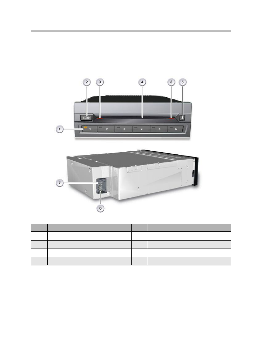
CD Changer
The new 6-disc CD changer (CDC) is available for the E70 the first time that a single-slot
CD changer has been fitted in a BMW vehicle. It is manufactured by Alpine. The CD
changer is integrated on the MOST network.
35
E70 Audio Systems
Index
Explanation
Index
Explanation
1
Buttons for operating trays
5
CD drive eject button
2
Load button for CD drive
6
MOST
3
Status display
7
Power supply
4
CD drive slot
Single-slot CD changer means that the CDs are loaded individually into the device with-
out a magazine. A CD can be loaded by pressing the load button, followed by the button
for the operating tray of the CD to be inserted. If no button is pressed after the load but-
ton has been tapped, the LED in the operating tray button assigned to the first free tray
flashes. In the meantime, the tray moves into position.
When the tray is in the correct position, the status display begins to flash and the CD can
be loaded. The contents of the CD are read as soon as the CD is inserted. The next CD
cannot be inserted until the contents of this CD have been read. The rapid loading fea-
ture must be activated to be able to insert all CDs immediately one after the other. To do
this, the load button must be pressed for approximately 2 seconds. The LEDs in the
operating buttons assigned to free trays begin to flash. Up to 6 CDs can be inserted one
after the other, depending on the number of trays free. The contents of the CDs inserted
are read either once the final free tray has been filled, on expiry of a time out or if the load
or eject button is pressed. An individual CD can be ejected by pressing the eject button
followed by the operating button concerned. Pressing and holding the eject button ejects
all the CDs.
The CDs cannot be loaded unless the shutter is open. The status display flashes when it
is possible to insert a disc. Operation is described in detail in the Owner's Handbook for
the vehicle.
36
E70 Audio Systems
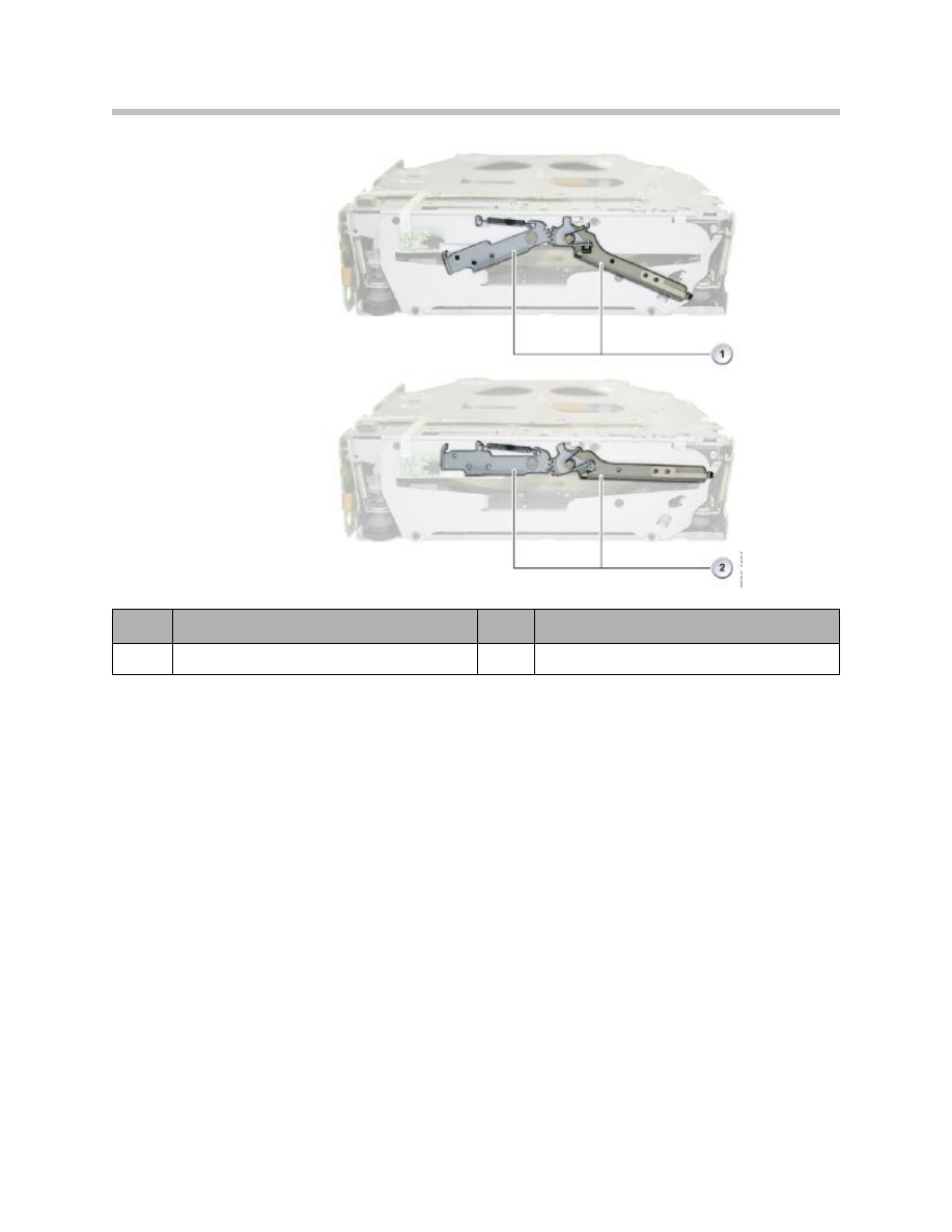
Single-slot CD Changer Shutter
(Front view without trim panel )
Index
Explanation
Index
Explanation
1
Shutter closed
2
Shutter open
The CD changer supports the following compressed file formats:
• MPEG-1 Layer 3 Audio (MP3) with ID3 tag version 1 and version 2
• Windows Media Audio (WMA) with WMA tags
• Advanced Audio Coding (AAC).
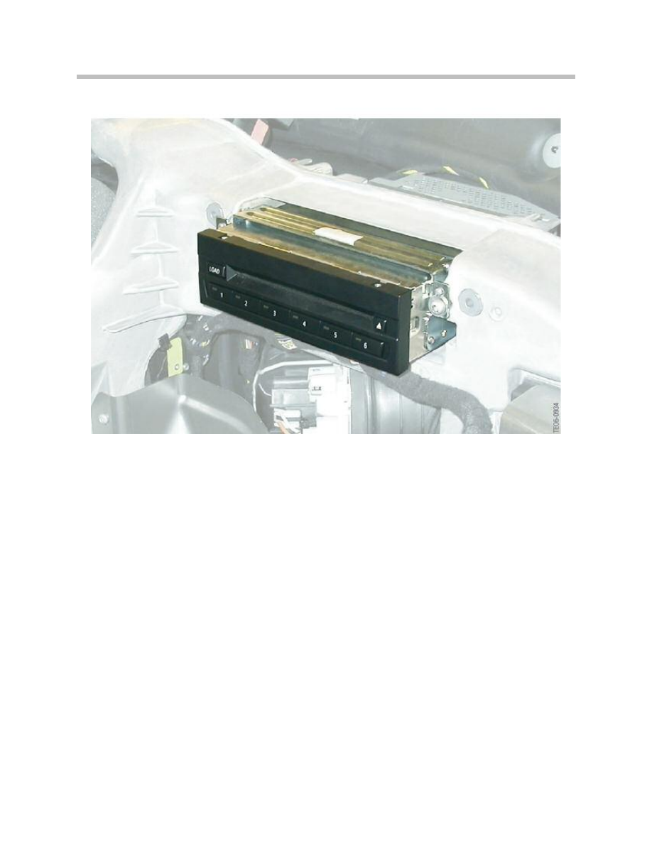
These files are decoded in the CD changer. The CD changer is accessible when the
glove compartment is open. The following graphic shows how the CD changer is con-
nected to the cross-member.
The data on the CD is decoded by the CD changer and converted into the digital MOST
format.
If the vehicle is equipped with the stereo or HiFi speaker system, the digital data on the
CD is sent to the head unit via the MOST. Here they are converted to analogue data and
output via the amplifier and the speakers.
If the Top-HiFi system is installed, the decoded audio data is sent directly to the Top- HiFi
amplifier via the MOST from where it is output. This direct transmission bypassing the
head unit is made possible because data conversion and sound adjustment take place
exclusively in the Top-HiFi amplifier.
37
E70 Audio Systems
Single-slot CD Changer Installation Location

Retrofitting a CD Changer
The fiber optics conductors for connecting the CD changer are arranged at the fiber
optics connector in the luggage compartment such that they are not incorporated in the
MOST ring. After retrofitting a CD changer, the fiber optics conductors for the CD chang-
er preparation are unplugged at the fiber optics connector and connected to the MOST
ring. It is then necessary to code the entire vehicle.
Audio Jack
The audio jack is used to connect an external audio source such as MP3, cassette or CD
playback devices. The audio jack (Aux In) is standard equipment in the E70. It is located
below the center armrest. A 12-V socket outlet is located in the immediate vicinity of the
audio jack.
38
E70 Audio Systems
Diagnosis
It is possible to run diagnostics on the HiFi amplifier thanks to its connection to the K-
CAN. The following measures have been implemented to minimize interference during
AM and also FM reception:
• Tailgate hinges with integrated ground straps
• Low-noise AM and FM antenna amplifiers
• ground connection on both silencers
• Shielded Wave barrier.
An audio test CD is available from the EPC that can be used to test drives.
The BMW diagnostic system contains the control module entries listed in the table:
Key for the table above:
39
E70 Audio Systems
Service Information
CHAMP Professional radio
CCC Professional navigation system
CHAMP-GW
CCC-GW
CHAMP-BO
CCC-BO
CCC-A
CCC-ANT
CCC-ASK
Index
Explanation
Index
Explanation
GW
Gateway
A
Applications
BO
User interface
ANT
Antenna tuner
NAV
Navigation system
ASK
Audio system controller

Reset
All head units can be reset by following the procedure described below:
• Switch system ON/OFF
• BMW diagnostic system
• Disconnect from vehicle electrical system.
There is no specific button or button stroke combination on the CHAMP for performing a
reset.
The CCC can be reset by simultaneously pressing and holding the eject buttons on the
DVD and CD player and the rotary push button for approximately 10 seconds. The CID
becomes blank. The CCC is then restarted.
Note: The MOST gateway (CHAMP, CCC) is muted for 2 seconds when a
MOST control module is reset.
Service Concept
The CHAMP is replaced as complete units.
The service concept of the CCC permits replacement of individual assemblies.
The following assemblies can be replaced:
• Fan
• CD and DVD player
• Front panel
• HIP
• Yaw rate sensor.
Note: Observe the ESD guidelines in case of replacement. The CCC must not
be stood on its rear panel as the sockets may be damaged by the weight
of the unit.
In diagnostics, the following diagnostic queries can be issued for the amplifiers available:
HiFi Amplifier
• Responds to diagnostics thanks to K-CAN connection
• Separate control of individual audio channels
40
E70 Audio Systems

Top-HiFi Amplifier
• Output of sinus tones by means of an internal sine-wave generator (configurable
parameters: frequency, volume, speaker channel)
• Separate control of individual audio channels
Antenna Diagnosis
Antenna diagnostics on the E70 proceeds in the same way as diagnostics on the BMW 3
Series (E90, E91, E92), BMW 5 Series (E60, E61) and BMW 6 Series (E63, E64):
The self-diagnosis procedure for the diversity module is initiated in the diagnosis module
of the BMW diagnosis system. The self-diagnosis comprises a check of the antenna
inputs based on a DC measurement.
If the check proves positive, each individual FM antenna is switched on one after the
other in a specified sequence and the signal quality evaluated (antenna scan). The AM
reception can be evaluated in the LW, SW and MW range with the AM amplifier switched
on and off. The diagnosis system evaluates the measurements and deduces the status
when the self-diagnosis of the diversity module provides a positive result.
This procedure can also be carried out manually by switching the CHAMP into service
mode:
The signal quality and field strength of the station currently tuned in can be displayed in
service mode.
Service Mode
Service Mode is Accessed as Follows:
• Open Start menu
• Press and hold the controller for at least 10 seconds
• Move the controller 3 stops to the right
• Move the controller 3 stops to the left
• Move the controller 1 stop to the right
• Move the controller 1 stop to the left
• Move the controller 1 stop to the right
• Press the controller once.
Note: To exit Service mode press the Menu button.
41
E70 Audio Systems
42
E70 Audio Systems
Note: Low values with regard to signal quality and field strength may indicate
to damaged antennas or the absence of terminal Rad_On.
Terminal Rad_On supplies power to the antenna amplifier and the diversity module.
Hissing or Interference on Radio
Check the following in the event of hissing or interference with radio reception:
• Station tuning
• Mechanical damage to the antenna structure
• Power supply terminal Rad_On for the antenna amplifiers in the diversity module.
• Antenna connector at diversity module
• Diversity module connected to ground by securing screws
• Antenna connector on radio or navigation system.
The following measures have been taken in the E70 to minimize reception interference
of AM and FM stations:
• Tailgate connected to ground by the tailgate hinges with integrated ground straps
• Low-noise AM and FM antenna amplifiers with direct ground connection
• Ground connection on the left and right silencer
• Shielded Wave barrier.
The ground connection on the two silencers helps to suppress interference transmitted
from the engine compartment (ignition electronics) along the exhaust system.
The exhaust system is a wave guide and, if no ground straps are used, it carries high-fre-
quency interference to the rear end of the vehicle. At the end of the exhaust system, the
interference is radiated out and couples into the antenna structures located at the rear of
the vehicle. The ground straps on the silencers connect the interference to ground, there-
by suppressing the interference. These ground connections have already been fitted to
the BMW X5 (E53).
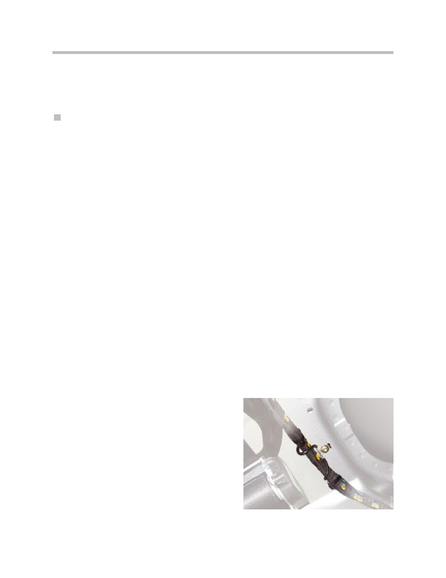
The shielded wave barrier connects to ground the
screen of the coaxial line between the head unit
and antenna diversity on the D-pillar. Interference
transmitted by the screen is therefore conducted
away to ground.

CD Changer
If the eject button is no longer working, a CD can be ejected using the diagnostic tester. If
the CD is mechanically jammed in the drive, it is necessary to send in the CD changer.
When the MOST bus enters sleep mode, the contents of the CD that has been inserted
and read is stored inside the head unit. There is therefore no need for this data to be read
once more when the MOST boots up again. The data is not saved in the event of a low
voltage situation before the MOST has entered sleep mode or a voltage interruption with
the MOST active. For this reason, the contents of the inserted CDs have to be read once
more when the MOST boots up.
43
E70 Audio Systems
Document Outline
- Main Menu
- Intro to Advanced Body Electronics
- E65 Power Management
- E65 Power Module
- E65 Car Access System
- E65 Driver Information
- E65 Body Electronics
- E65 Central Body Electronics
- E65 Remote Control Services
- E65 Automatic Trunk Lid Lift
- E65 Windshield Wiping Washing
- E65 Seat, Mirror and Steering Column
- E65/66 Model Update
- E65/66 Comfort Access
- E6x Voltage Supply and Bus Systems
- E6x Body Electronics
- E6x Body Electronics
- E6x 9/05 Model Updates
- E6x Driver Information Systems
- E90 Voltage Supply and Bus Systems
- E90 General Vehicle Electrical
- E90 General Vehicle Electrical
- E90 General Vehicle Electrical II
- E90 Driver Information Systems
- E90 Entertainment and Communication
- Car Communication Computer
- Head-Up Display
- Head-Up Display (First Generation)
- E70 Head-Up Display (Second Generation)
- E70 Audio Systems
- BMW Night Vision
- Glossary
Wyszukiwarka
Podobne podstrony:
07b E70 Audio Systems
07 E70 Audio Systems WB
Ćwiczenie 16, Zoologia ogólna i systematyczna - KURS DUŻY
Ćwiczenie 16, Zoologia ogólna i systematyczna - KURS DUŻY
Navigation and Audio System
diagnostics Audio System
Audio System for Built In Type Amplifier
Audio System for Separate Type Amplifier
93ZJ Secc 8F Audio Systems
09 E65 Audio System
04a E65 Audio System
96ZJ 8F AUDIO SYSTEMS
[16]Sterowniki urządzeń w systemie 1 2
16 Battery Charging System
AUDIO SYSTEM SECTION 9F 17
więcej podobnych podstron