
Service
The 2.3 l petrol engine
in the LT ‘97
Design and Function
Self Study Programme
Customer Service
189
2
...is not impossible.
Volkswagen Commercial Vehicles is featuring
a 2.3 l petrol engine in its LT '97 range as a
high performance option.
Find out more about it in this self study
programme!
A commercial vehicle with a petrol engine?

3
Page
Overview ........................................................................................ 4
Engine - mechanical ...................................................................... 6
Oil circuit ........................................................................................ 8
Cooling system .............................................................................. 10
Fuel supply ..................................................................................... 11
Self check ....................................................................................... 13
Injection and ignition system....................................................... 14
System overview........................................................................... 16
Ignition system .............................................................................. 18
Injection system ............................................................................ 28
Idling control.................................................................................. 32
Exhaust cleaning ........................................................................... 35
Functional diagram ....................................................................... 38
Self diagnosis................................................................................. 41
Self check ....................................................................................... 45
The Self Study Programme is not a repair
manual!
For information on testing, adjustments and
repairs refer to the appropriate customer
service literature.
Note!
New
4
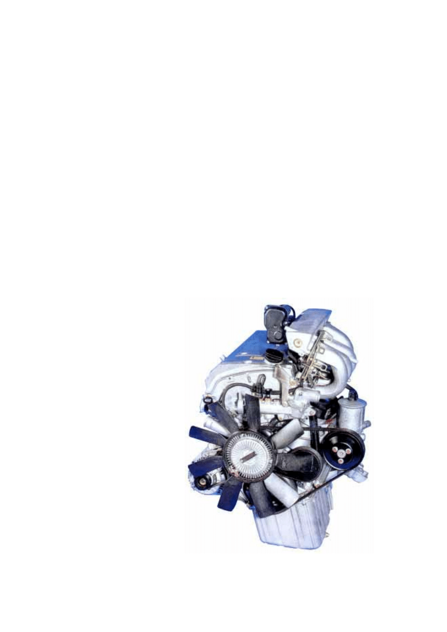
Overview
The new 2.3 l petrol engine
has been specially developed for commercial
vehicles. It delivers high level torque over a
wide range of revs.
189-61
189-01
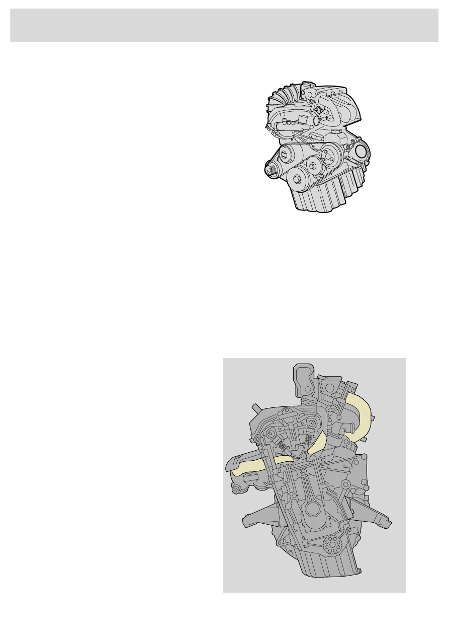
The engine has a cross flow cylinder head with
four valve technology. This makes for good
fuel mixing and therefore low emission
combustion.
5
10
20
30
40
50
60
70
80
90
100
110
0
0
1000 2000 3000 4000 5000 6000 7000
210Nm
105KW
100
120
140
160
180
200
220
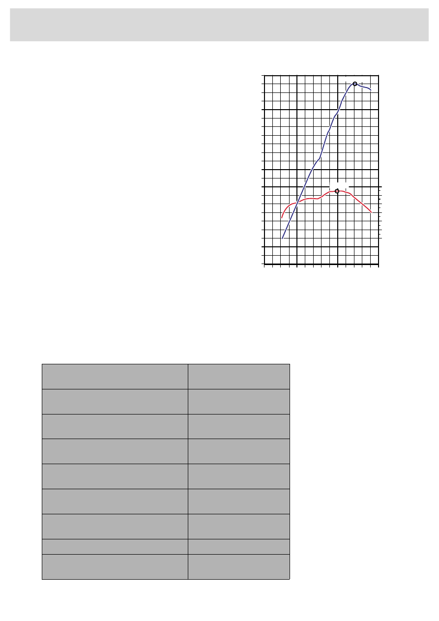
The torque and performance diagram
shows a maximum torque value of 210 Nm.
The torque value is over 180 Nm in an engine
speed range of 1500 to 5500 1/min. The engine
delivers its maximum output of 105 KW at
5500 1/min.
This permits constant and strong tractive
power even with heavy loads. Throughout the
entire engine speed range it is possible to
drive economically yet with powerful
acceleration and few gear changes.
Data
Engine abbreviation
AGL
Cylinders
R4
Capacity
2295 cm
3
Bore
90.9 mm
Stroke
88.4 mm
Compression
8.8 : 1
Power
105 kW/ 143 HP
at 5500 1/min
Maximum torque
210 Nm at 4000 1/min
Engine management
Siemens Motronic
189-76
6
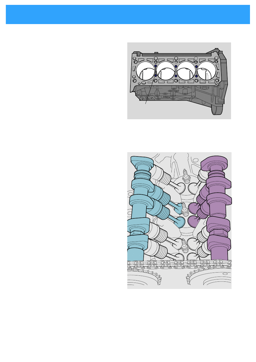
Engine - mechanical
Engine
The cylinder crank case is made of cast iron.
The top section gets very hot from the
combustion. Coolant flows through the
cooling slit, dissipating the heat.
4-valve technology
Each cylinder has
-
two inlet valves and
-
two outlet valves.
The 4 valves are operated by two overhead
cam shafts via hydraulic bucket tappets.
The benefits of the 4-valve technology are
-
high traction power and good power
delivery even at low and medium revs,
-
high level cylinder filling
-
low fuel consumption
-
fewer harmful substances in exhaust.
189-51
Outlet side
Inlet side
Cooling slit
189-71
7
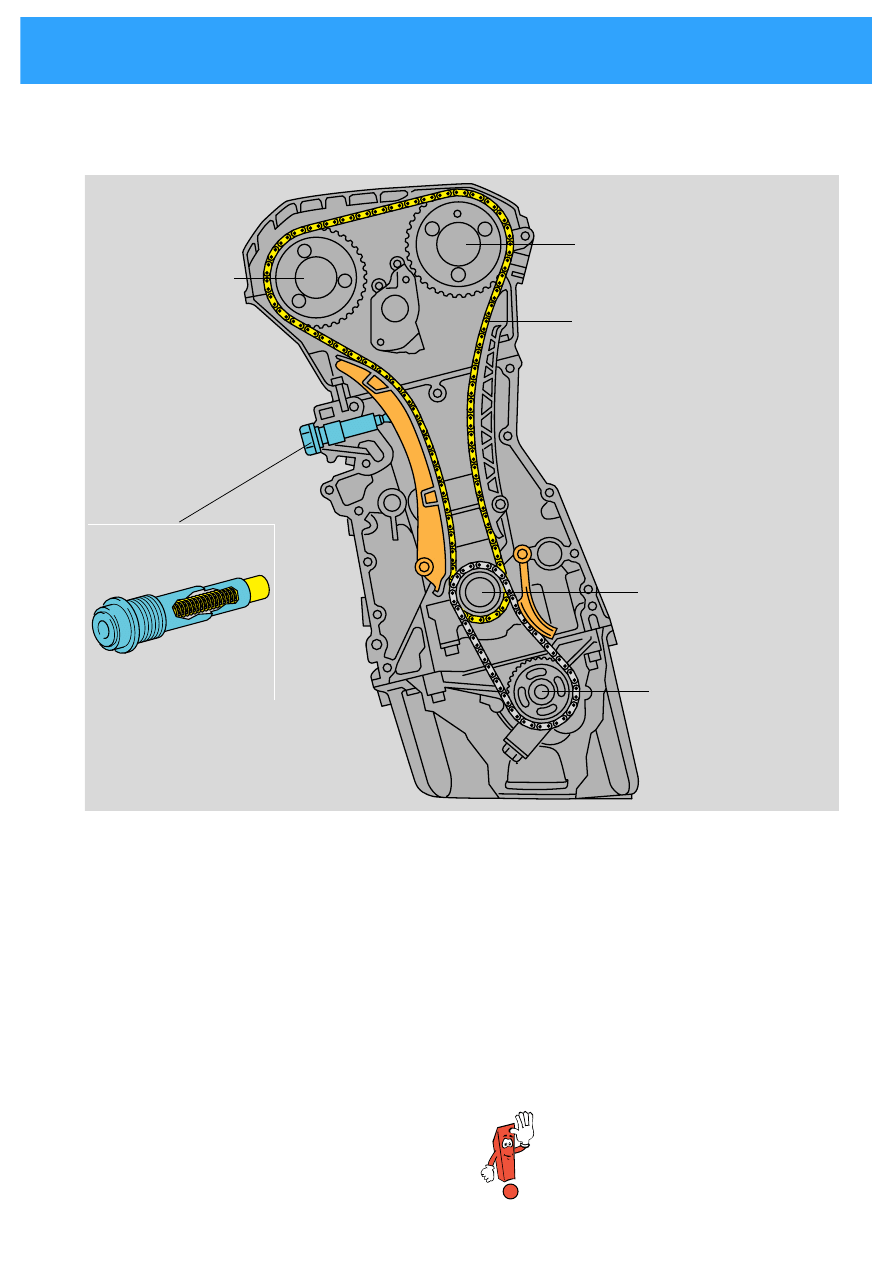
Control
189-55
timing chain
oil pump
crank shaft
chain tensioner
189-56
inlet cam shaft
outlet cam shaft
The cam shafts are driven by the crank shaft
and a chain.
A second chain drives the oil pump.
Chain tensioner
A chain tensioner tensions the timing chain. It
functions by oil pressure. A locking segment
ensures that the timing remains tensioned
even of there is no oil pressure.
It is only possible to reset the
locking segment when the chain
tensioner has been taken out.
8
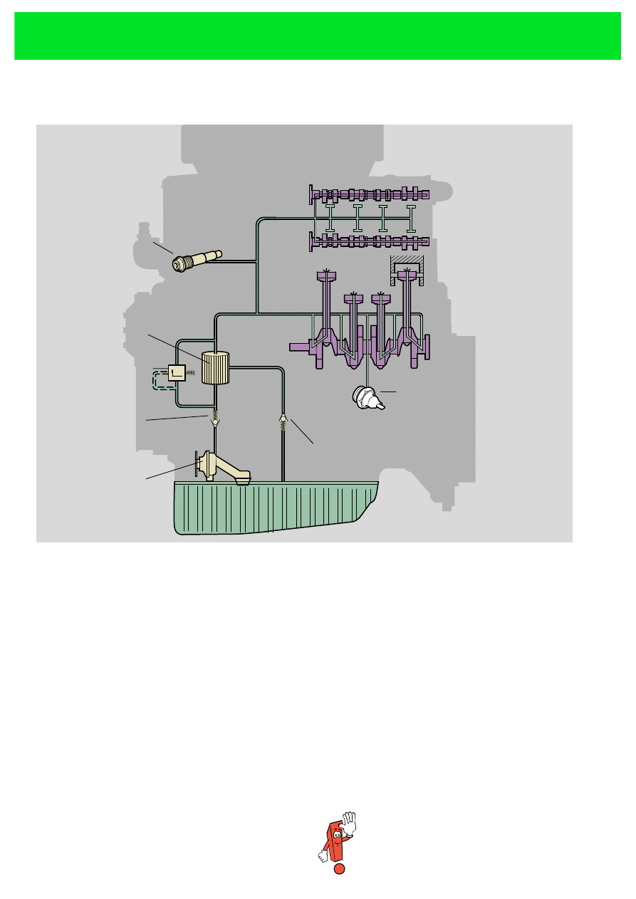
Schematic diagram of oil circuit
189-59
Chain tensioner
Oil filter
Pressure limiting
valve
Oil pump
Oil pressure switch
Return valve
Return stop
The oil pump
is a sickle pump. It pumps the oil
-
out of the oil sump
-
through the oil filter
-
to the cam shafts
-
to the cylinder head and
-
to the chain tensioner.
There is an excess pressure valve.
For the piston cooling there are holes in the
connecting rod eye through which the oil is
pumped to the base of the piston via the crank
shaft bearing.
A return valve and the return stop prevent the
oil from running back out of the engine.
If the oil filter is blocked the pressure limit
valve opens the by-pass line.
The oil pressure switch is white. Its
function range is between 0.2 and
0.5 bar.
Oil circuit

9
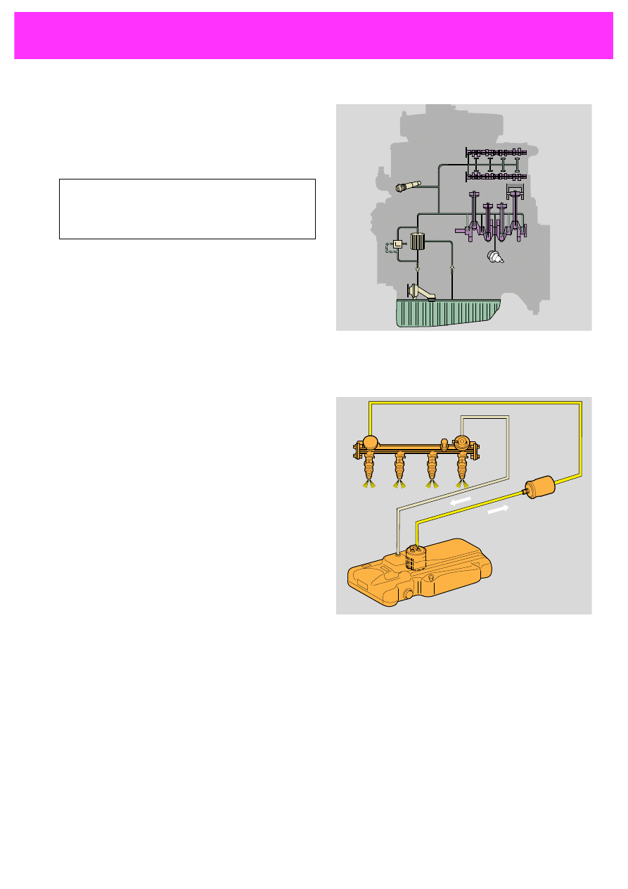
Crank case venting
189-74
throttle valves
breather line
There is a breather line between the crank case
and the intake manifold. The gases flow
-
from the crank case
-
through the breather line and the throttle
valves
-
into the intake manifold.
When idling and under part load fresh air
flows through the crank case venting system
into the crank case.
The fresh air mixes with the gases in the crank
case. This prevents sludging of the engine oil.
10
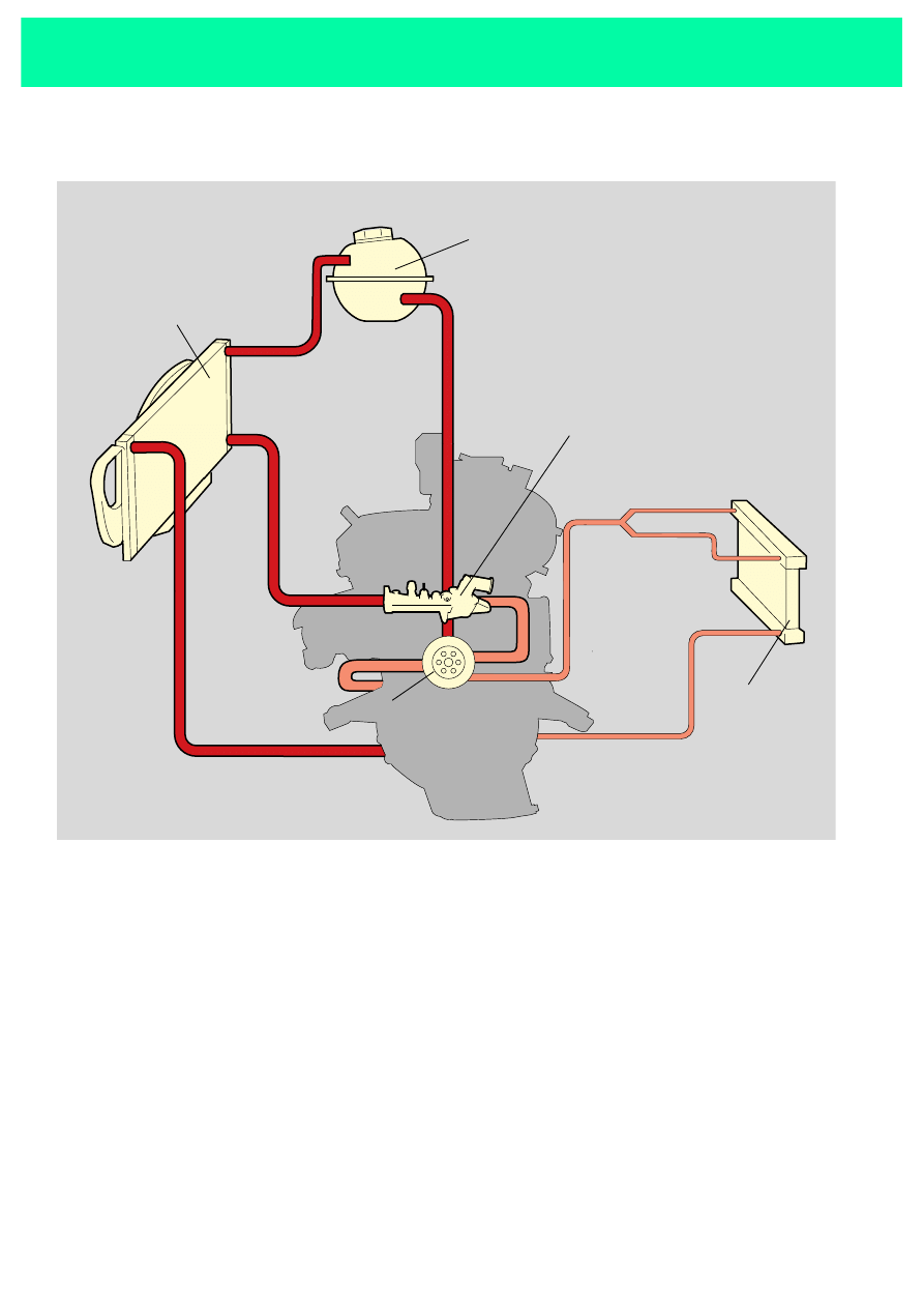
Cooling system
Schematic diagram of cooling circuit
189-58
cooler
expansion tank
temperature
controller
coolant pump
heating system
heat exchanger
Minor circuit
The coolant pump circulates the cold coolant
around the engine block and, if required,
around the heating system/heat exchanger.
Major circuit
The temperature controller regulates the
engine temperature. Once the engine has
reached its operating temperature a
thermostat valve opens and the coolant pump
pumps the hot coolant out of the engine into
the cooler. There it is cooled and flows back to
the coolant pump.
The expansion tank compensates the
expansion of the coolant at high temperatures.
11
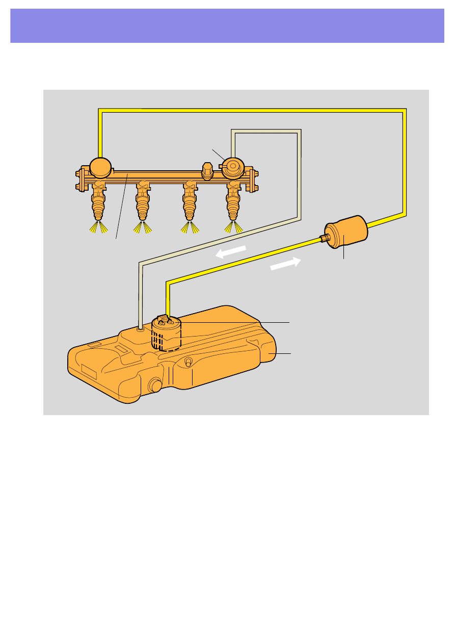
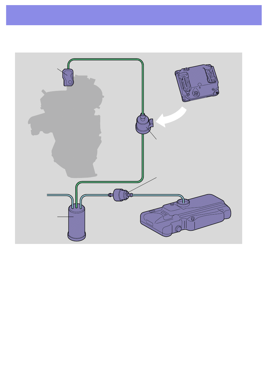
The fuel pump
pumps up the fuel, pushing it through the fuel
filter and the diaphragm pressure controller to
the injection valves.
The diaphragm pressure controller
controls the fuel pressure in the header,
dependent on the intake manifold pressure. It
channels excess fuel back into the fuel tank.
Fuel supply
Schematic diagram of fuel system
189-57
diaphragm pressure
controller
header
fuel filter
fuel pump
fuel tank
12
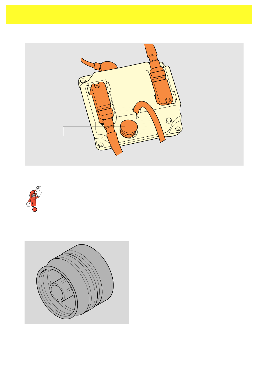
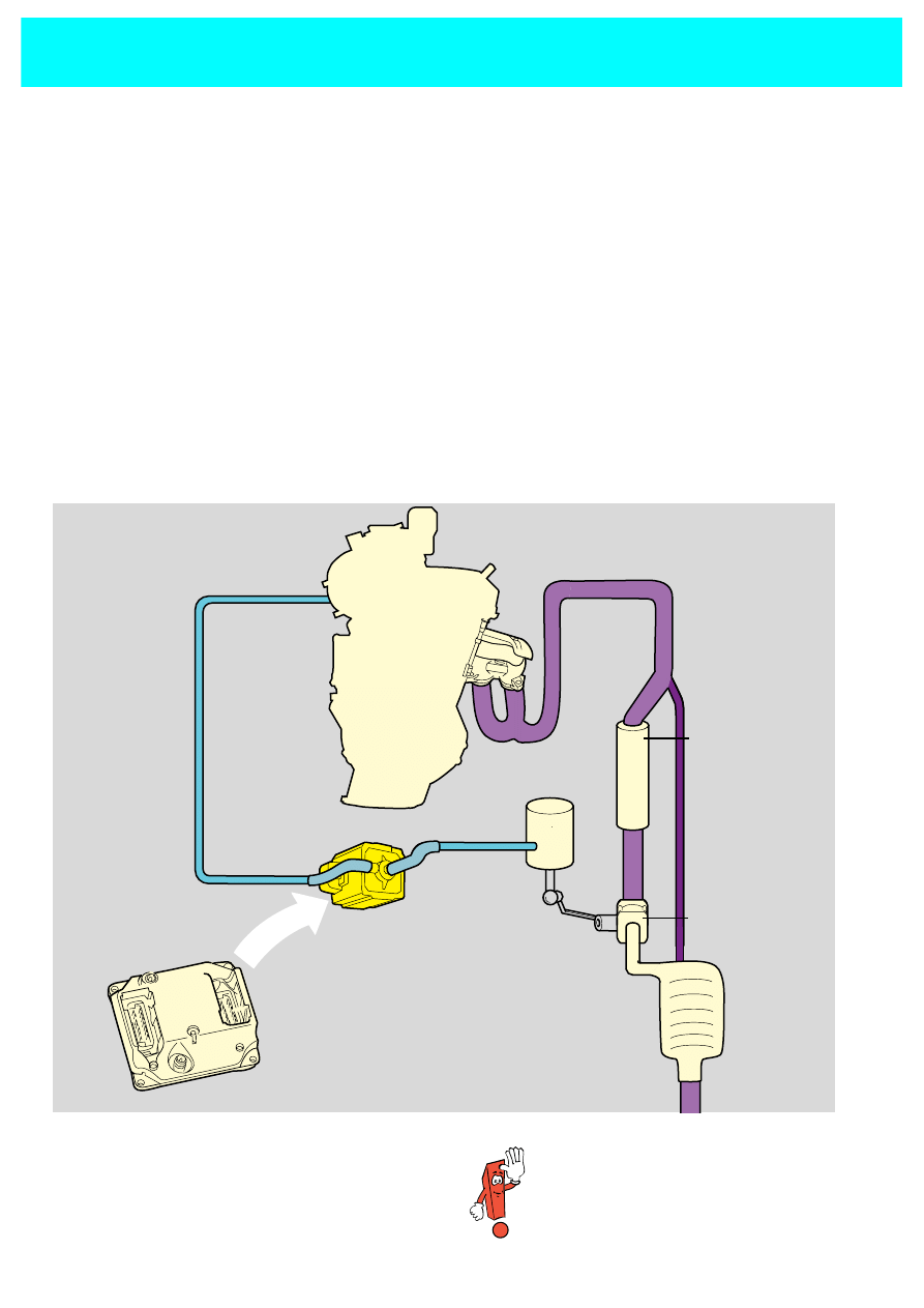
Active carbon filter system
189-73
active carbon
container
breather line
valve for tank venting
throttle valve
control unit
return valve
The active carbon filter system consists of
-
an active carbon container
-
air supply and exhaust lines between tank
and active carbon container
-
return valve which opens the line in the
opposite direction, depending on pressure
-
a breather line from the active carbon
container to the exterior
-
a line for fuel vapours between the active
carbon container and the throttle valve
control unit
-
and a valve which is controlled by the
engine control unit when fuel vapours are
to be fed to the mixture .
The active carbon system prevents fuel
vapours escaping into the environment. This
is achieved by:
•
creation of slight excess pressure in the
fuel tank when engine switched off
•
pressure equalisation with engine running
•
return of fuel vapours into combustion pro-
cess
Fuel supply
13
1.What is the oil for which is pumped through
the holes in the connecting rod eye to the base
of the piston?
2.Complete the following text!
The ____________________________ sucks up
the fuel, pumps it via the
____________________________ through the
____________________________ to the injection
valves.
The ____________________________ controls
the fuel pressure in the header depending on
the ____________________________ and chan-
nels excess fuel back to the
____________________________ .
Self check

14
Siemens Motronic
Ignition system
Responsible for:
•
calculating the advance
angle
•
adjusting the advance
angle
•
monitoring the ignition
coils
•
multiple ignition
Injection system
Responsible for:
•
calculating the injection
time
•
determining the injection
sequence
•
calculating the mixture
enrichment
Idling control
Responsible for:
•
ensuring smooth engine
running under all loads
•
maintaining idling speeds
under all loads
•
additionally: to heat the
catalytic converter after
ignition
Injection and ignition system
15
M
F
F
M
189-07
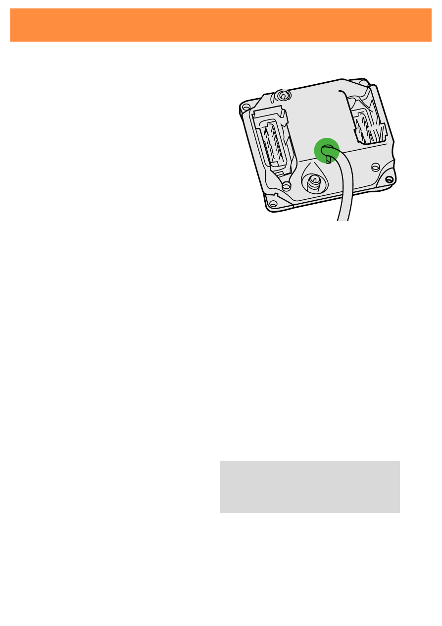
Engine speed sender G28
Pressure tube to sender for
intake manifold pressure
sender G71
Plug to engine
Plug to vehicle
Ignition map
balancing resistor
N221
189-08
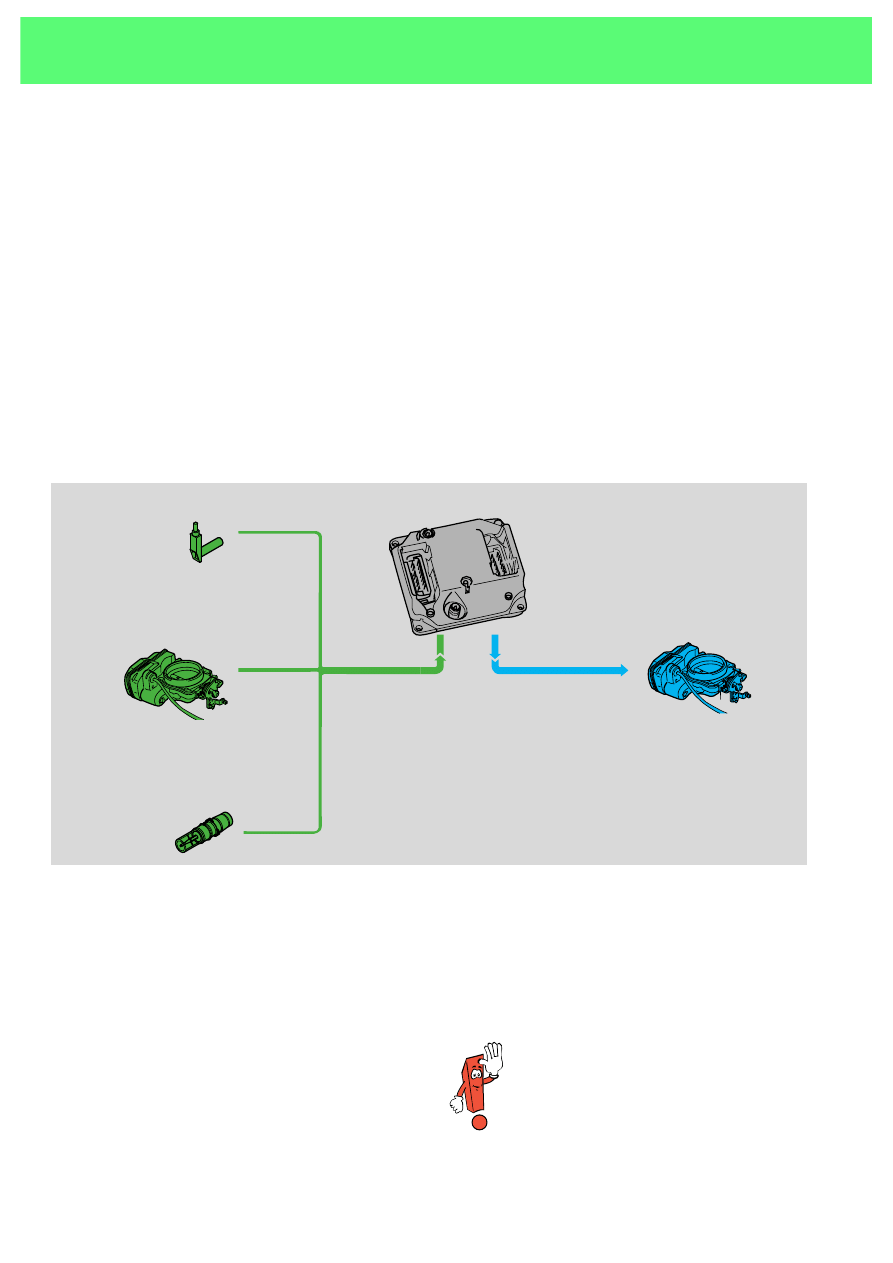
Ignition map balancing resistor
If using ROZ 91 instead of ROZ 95 the fixed
resistor in the control unit needs to be
removed.
The ignition map balancing resistor shifts the
ignition point to "delayed".
Plugs M and F have the same
construction. Check the labels on
the plugs and on the control unit.
16
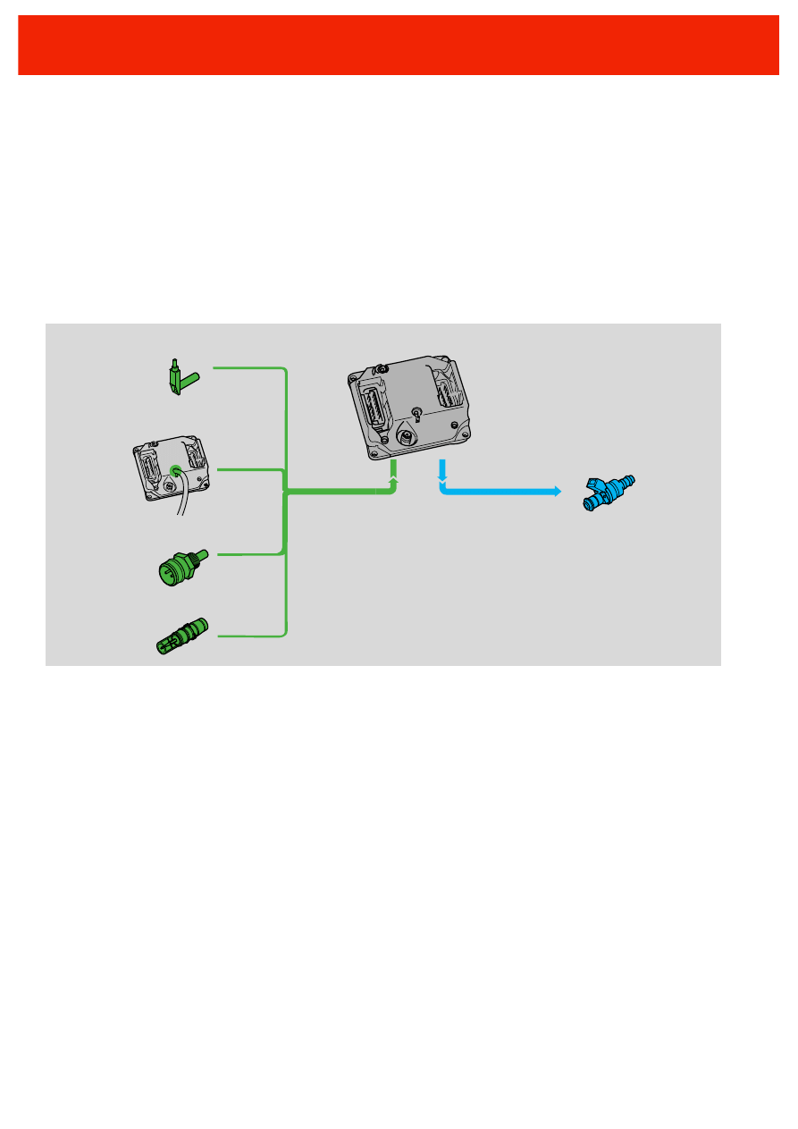
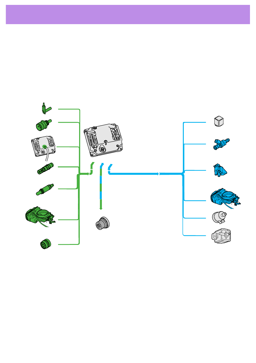
Engine speed sender G28
In control unit for Motronic J220:
-
Intake manifold pressure sender
G71
Sender for coolant temperature G62
Intake air temperature sender G42
Lambda probe G39
-
Throttle valve potentiometer
G69
-
Throttle valve positioner -
potentiometer G88
-
Idling switch F60
Ignition map balancing resistor N221
Control unit for Motronic
J220
In the Throttle valve control unit
J338:
Self diagnosis
connection
System overview
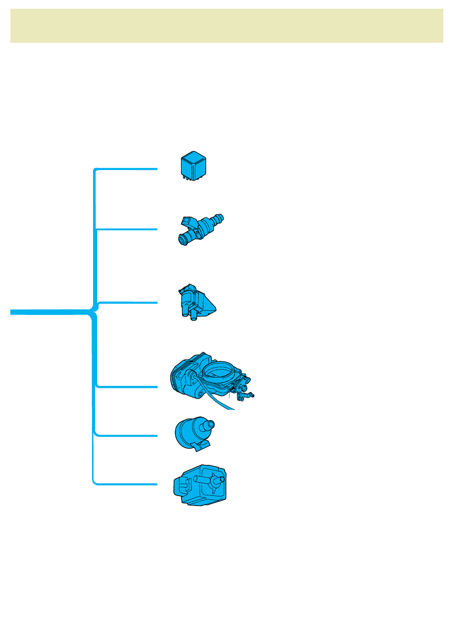
17
189-04
Exhaust flap valve N220
Valve for tank venting N80
In throttle valve control unit
J338:
-
Throttle valve positioner
V60
Cylinder transformers
N222, N223
Fuel pump relay J17
Injection valves N30, N31, N32, N33
18
The static load high tension distribution
system consists of:
-
the control unit for processing the input
signals
-
two ignition coils
-
each of which are allocated two spark
plugs.
The functions of the ignition system are:
-
to calculate the advance angle
-
to adapt the advance angle
-
to monitor the ignition coils
-
multiple ignition
J220
189-77
Intake air temperature sender G42
Intake manifold pressure sender G71
Engine speed sender G28
Sender for coolant temperature G62
Injection valves N30, N31,
N32, N33
Cylinder transformers
N222, N223
Ignition system
189-22
19
189,70
1
2
3
4
189-70
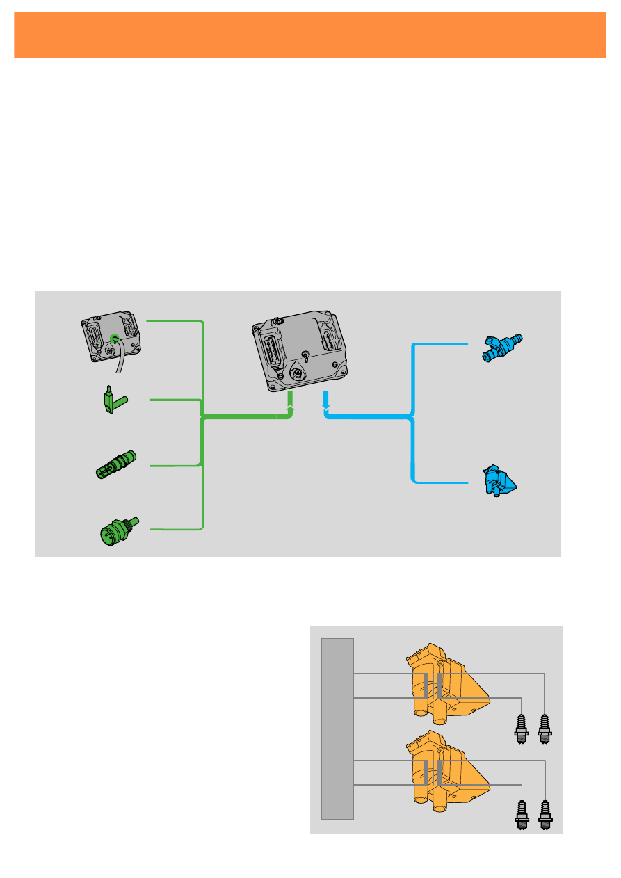
Double spark ignition
During each ignition cycle there is a spark on
both of the connected spark plugs. One is
triggered in the power stroke and one in the
exhaust stroke.
Electrical switching
10
Input signal ignition transformer N222
11
Input signal ignition transformer N223
P
Spark plug plug
Q
Spark plugs
Q
P
N222
N223
15
1
15
1
10
15
J220
11
(T17a)
31
189-24
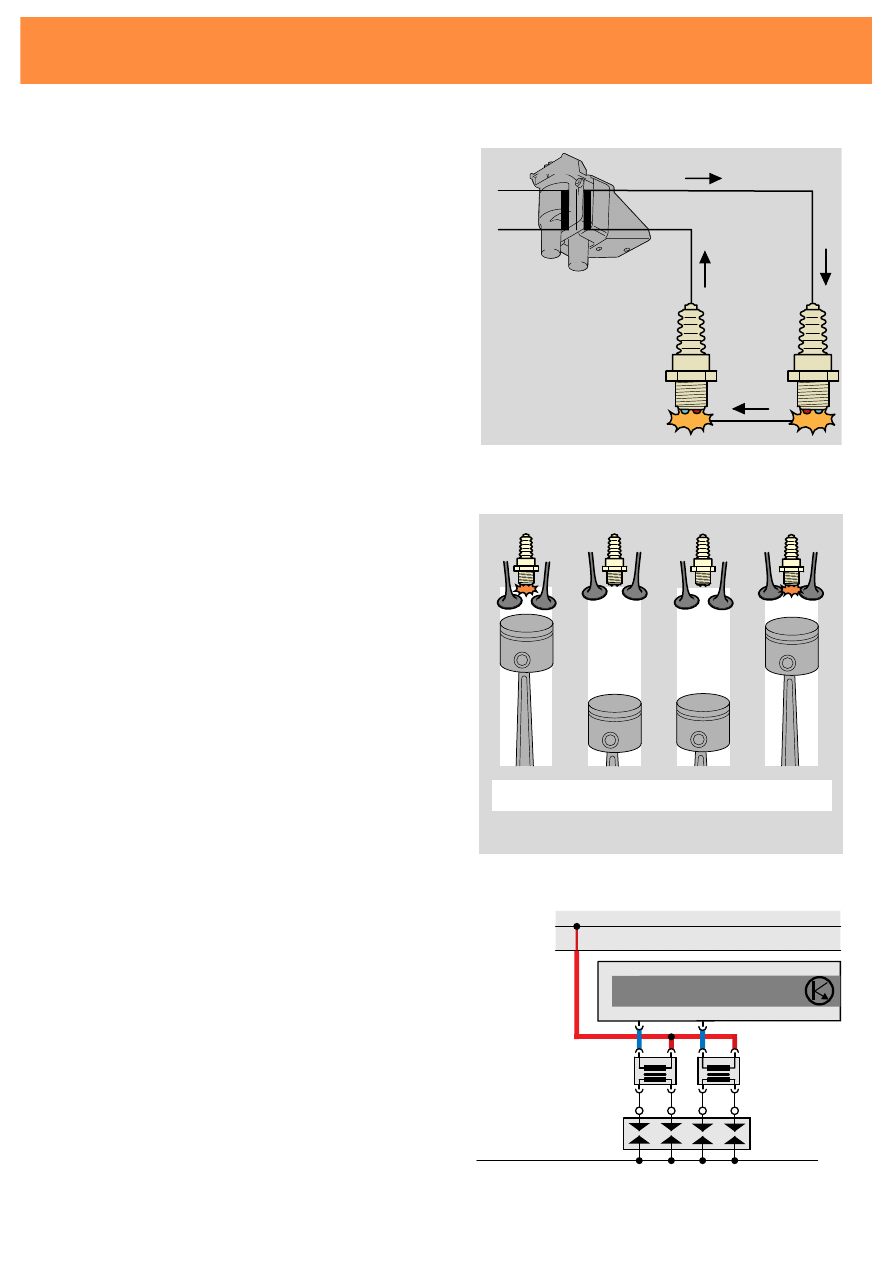
During ignition the engine control unit
interrupts the power supply to the appropriate
ignition coil. The sudden drop in voltage on
the primary coil induces a high voltage in the
secondary circuit. The discharge creates the
ignition sparks.
The secondary ignition coil, the spark plugs
and the engine earth form a closed circuit.
189-23
20
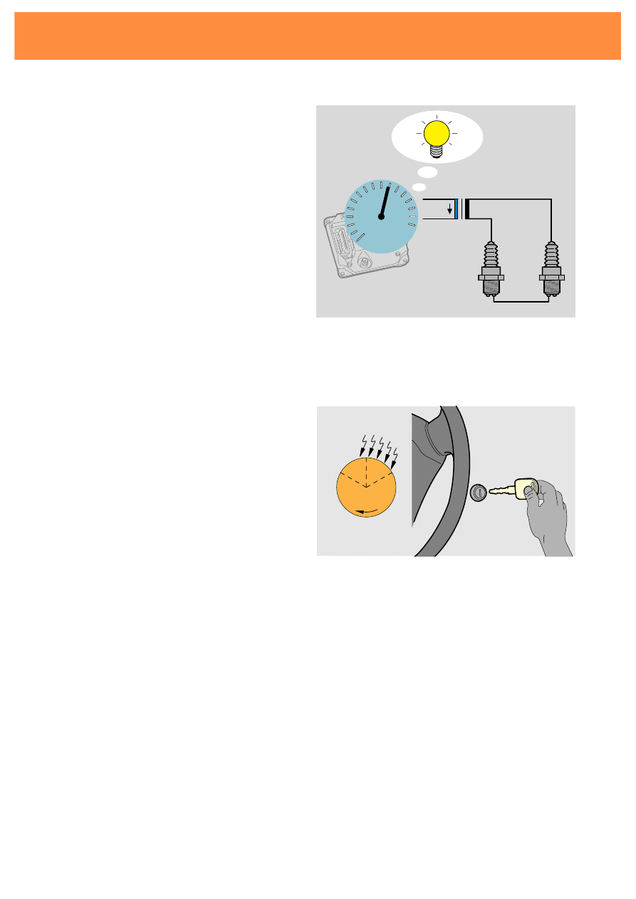
Multiple sparking
When the engine is started a series of sparks is
emitted instead of just one. This makes it
easier for the engine to start.
Multiple sparking only takes places when the
engine temperature is below 20
°C.
10
o
Monitoring the ignition coils
If faults arise in the ignition system the
catalytic converter can be damaged through
overheating. To protect the converter the
ignition coils are monitored. If an ignition coil
does not spark, the injection in the appropriate
cylinder is cut.
Ignition system
189-37
189-38
21
Advance angle adjustment
OT
:25
189-32
OT
8
8
189-33
OT
:02
189-34
OT
189-35
OT
:02
5
189-36
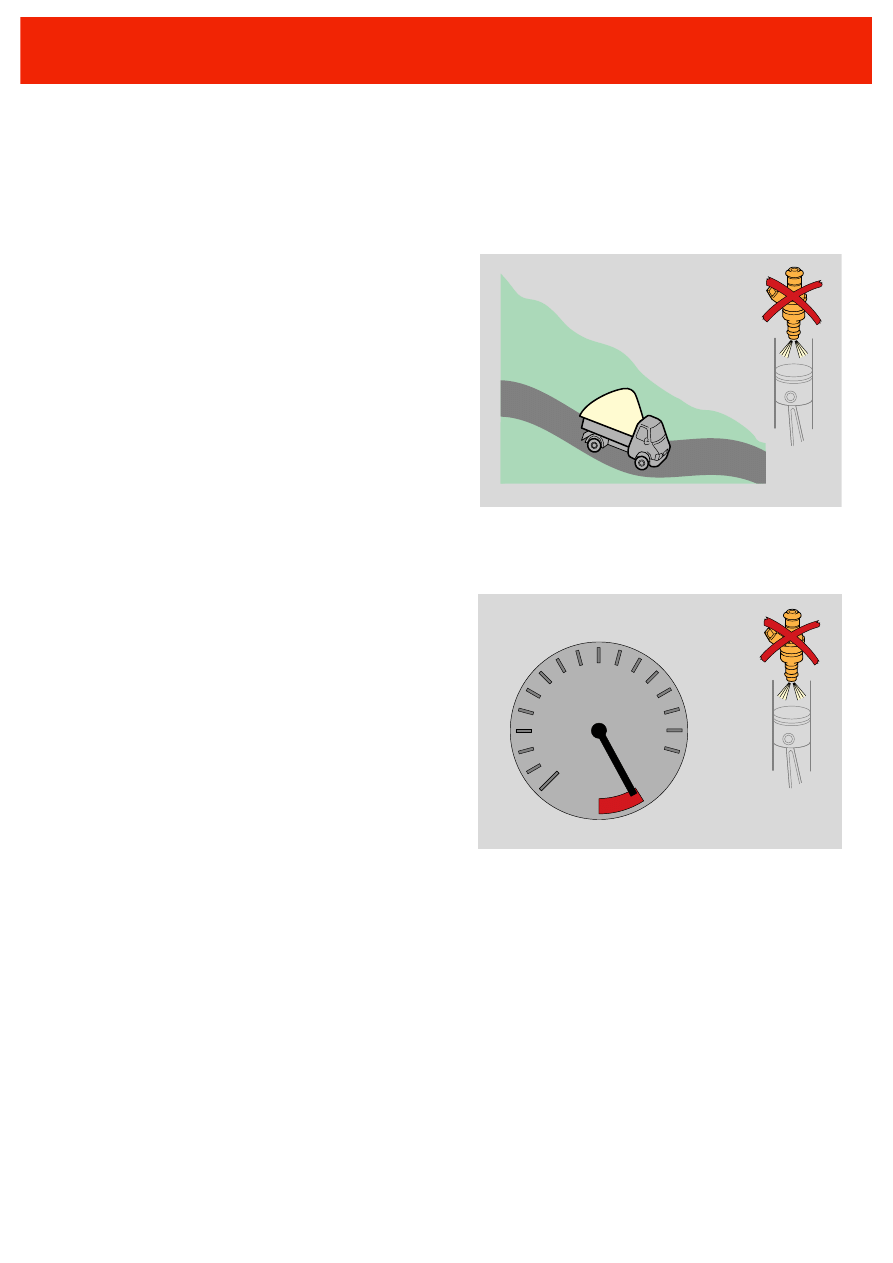
Load change
When travelling uphill there is a slight tendency
to jolting. After a load shift with traction the
control unit adjusts the advance angle to
"Delayed" for two seconds.
Prevention of engine knock
At higher air intake and coolant temperatures
there is a tendency for engine knock to arise. For
this reason the control unit sets the advance
angle to "delayed" in this situation.
Overrun cut-off
When moving from overrun to acceleration there
is jolt caused by the change in the torque. To
make this transition as gentle as possible the
control unit sets the advance angle to "delayed"
for two seconds.
Digital Idling Stabilisation DIS
The DIS supports the idling control by adjusting
the throttle flap. The idling speed is controlled
by the control unit adjusting the advance angle
up to 8
° before or after TDC.
Warming up phase
After starting the engine the engine control unit
adjusts the advance angle for roughly 25
seconds to "delayed". The combustion
temperature increases and the catalytic
converter heats up more quickly.
22
189-18
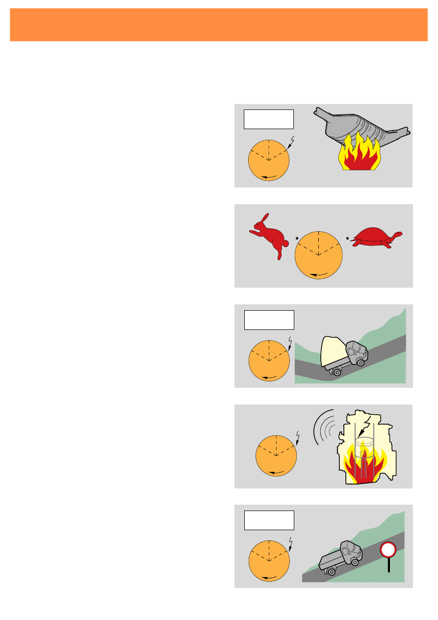
The engine speed sender G28
is an inductive sender. It registers the position
of the crank shaft and the engine speed.
189-67
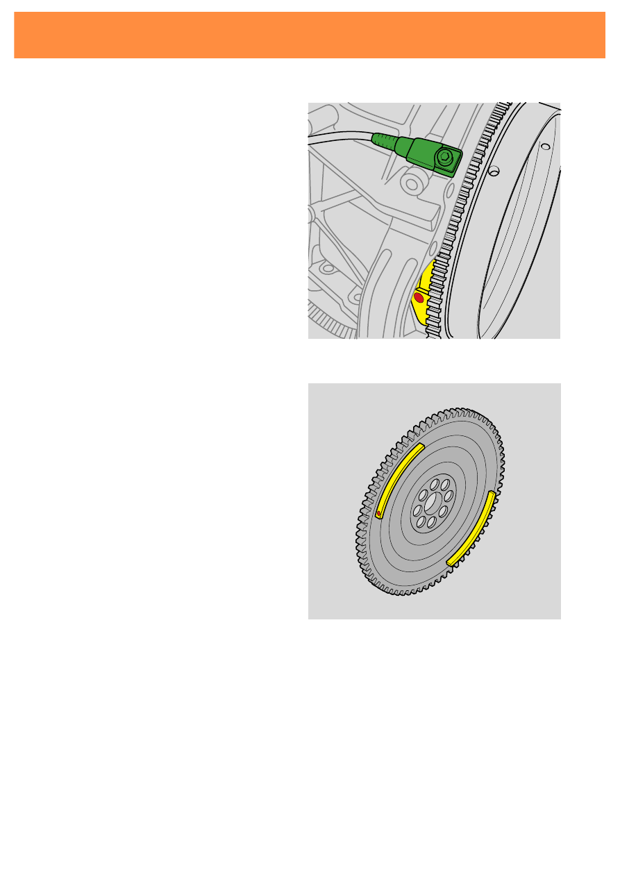
Segments are attached to the flywheel for the
sender to recognise.
When the segments pass over the sender this
changes the magnetic field. The engine
control unit calculates the engine speed from
this information.
There is also a permanent magnet on one of
the segments.
The control unit recognises the signal from the
segments with and without the permanent
magnet. It assigns the segment with the
magnet cylinders 2 and 3. In this way
cylinders 1 and 4 can be distinguished from
cylinders 2 and 3.
Ignition system

23
Application of signal :
Consequences of signal failure:
"Error message" self diagnosis:
Electrical switching:
1, 2 input signal - engine speed sender G28
1
2
G28
(T2)
J220
189-19
Engine speed sender G28
no signal/implausible signal
no magnet
speed implausible
The engine cuts out.
The engine cannot be started.
The engine speed signal is needed to calculate
-
advance angle
-
injection and
-
engine load.
24
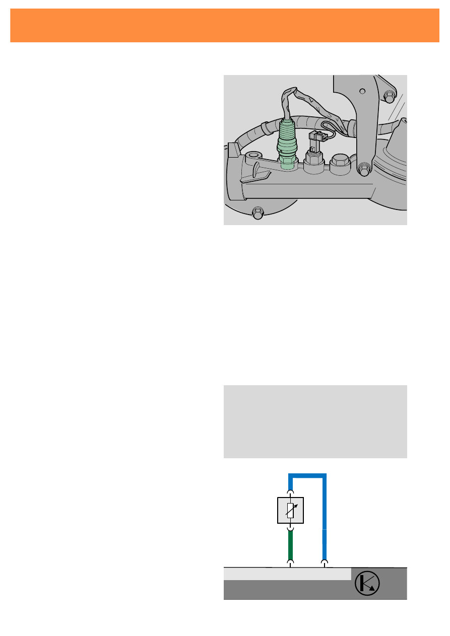
The coolant temperature sender G62
registers the temperature of the coolant and
relays the signal to the engine control unit.
The sensor is an NTC resistor.
189-13
Consequence of signal failure:
"Error message" self diagnosis:
Electrical switching:
7
input signal - coolant temperature sender
G62
9
output signal
J220
7
G62
9
(T17a)
Coolant temperature sender G62
short circuit
interruption
implausible signal
loose contact
The control unit creates substitute values.
These are so close to the actual value that the
error cannot be registered in the measured
data block. The error will, however, be
displayed in the error memory.
Application of signal:
-
recognition of engine temperature
-
calculation of advance angle
-
calculation of injection time
189-15
Ignition system
25
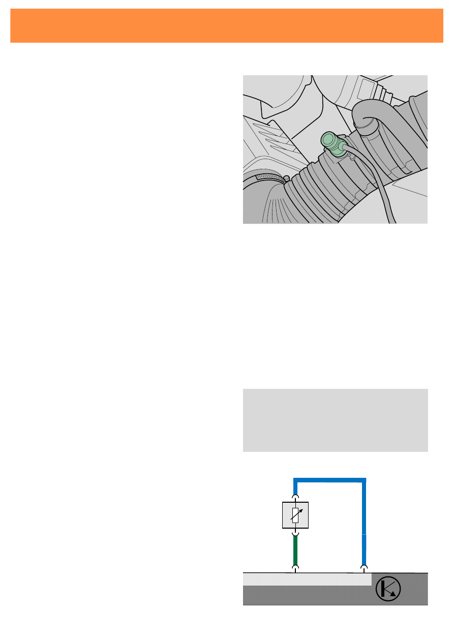
The intake air temperature sender G42
registers the temperature of the intake air and
relays the signal to the engine control unit.
The sensor is an NTC resistor.
189-16
Consequence of signal failure:
"Error message" self diagnosis:
Electrical switching:
16
input signal - intake air temperature
sender G42
9
output signal
J220
16
G42
9
(T17a)
Intake air temperature sender G42
short circuit
interruption
loose contact
The control unit creates substitute values.
These are so close to the actual value that the
error cannot be registered in the measured
data block. The error will, however, be
displayed in the error memory.
Application of signal:
-
calculation of advance angle
-
calculation of engine load
189-17
26
Ignition system
The intake manifold pressure sender G71
is in the Motronic control unit.
A pressure tube connects the manifold with
the intake manifold pressure sender.
The sensor is a piezoelectric resistor. It
changes its resistance depending on the
pressure.
Consequence of signal failure:
"Error message" self diagnosis:
Intake air temperature sender G71
implausible signal
no signal
If the manifold pressure sender malfunctions a
substitute value is calculated from the signals
from the engine speed and throttle flap
potentiometer sender signals.
Application of signal:
-
calculation of engine load

27
Notes
28
189-78
Intake air temperature sender G42
Intake manifold pressure sender G71
Engine speed sender G28
Sender for coolant temperature G62
Injection valves N30, N31,
N32, N33
Injection system
The functions of the injection system:
-
to calculate the injection time
-
to determine the injection sequence
-
to calculate the mixture enrichment
Function
The control unit calculates the required fuel
quantity and the appropriate injection time
from the input signals.
It controls two injection valves simultaneously.
29
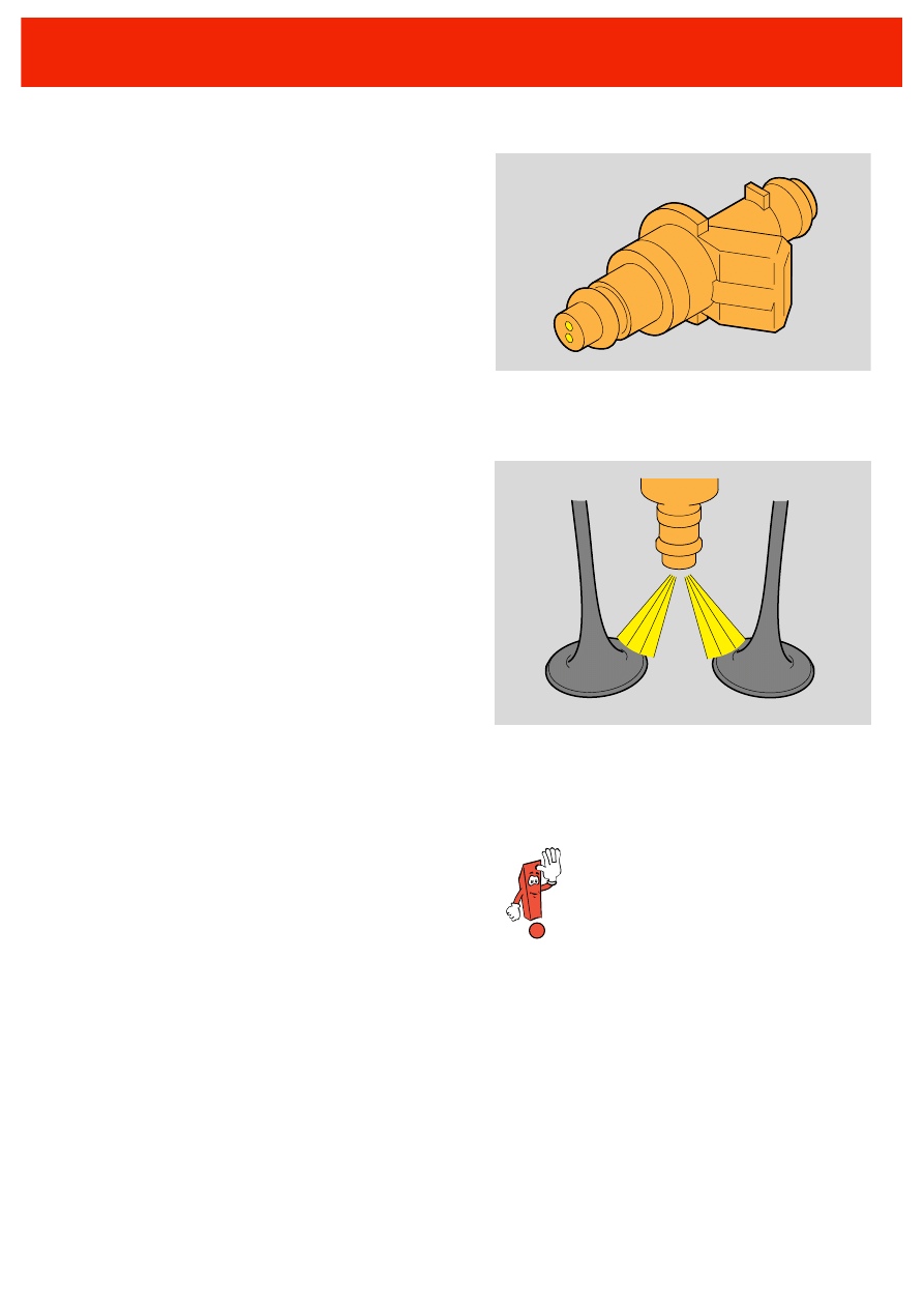
Injection valves N30 - N33
inject the fuel in a fine mist into the intake
channels. The fuel emerges from two holes
and is injected to the inlet valves.
The injection valves have no resistors in their
circuit. They have 12 V clocked control
voltage. A continuous 12 V supply would
destroy them.
189-69
189-68
The injection valves should not be
exposed to a continuous 12 V
supply.
30
189-41
189-42
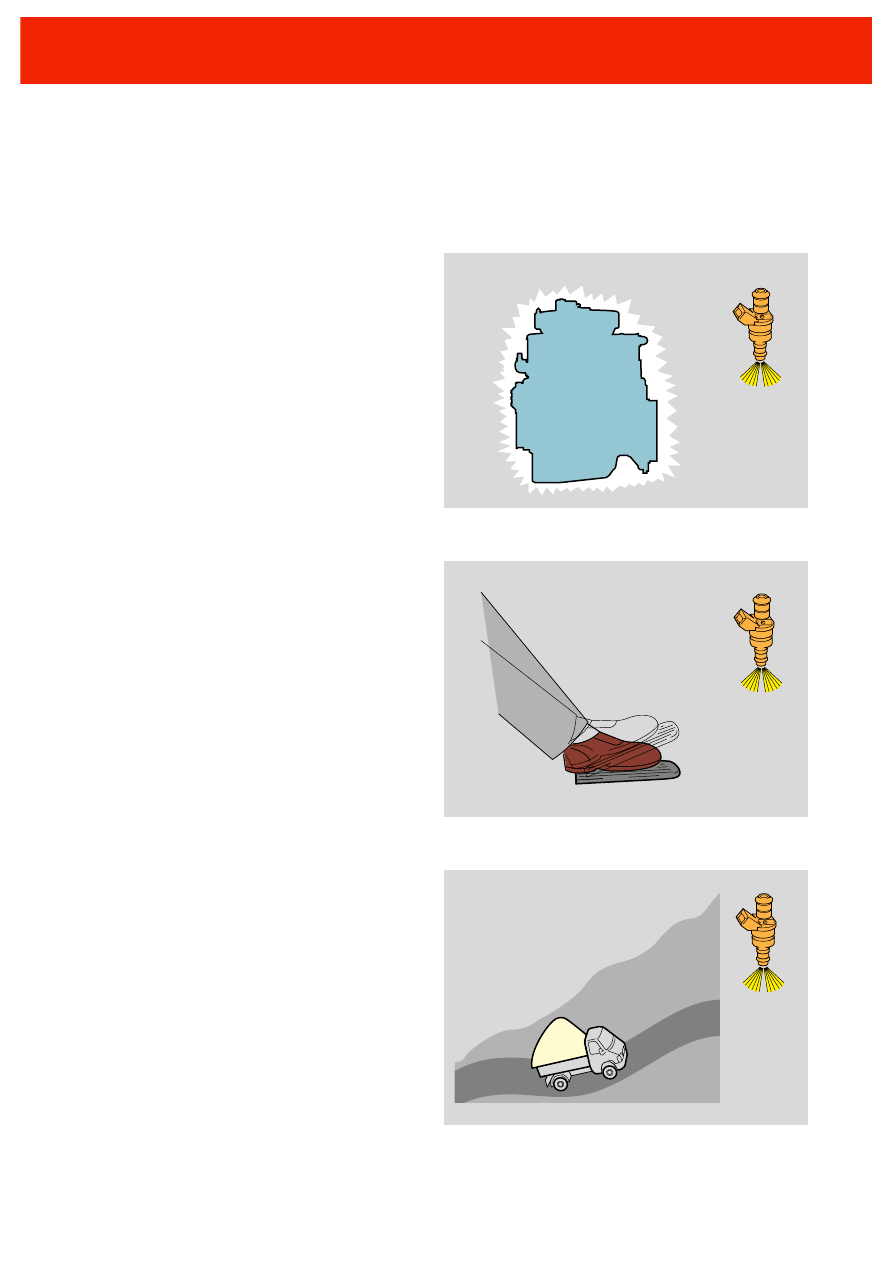
Mixture enrichment
Start/warm-up
A cold engine needs a rich mixture. This is
why the control unit increases the injection
quantity for a cold start and during the warm-
up phase.
189-40
Injection system
Acceleration
During acceleration the control unit enriches
the mixture to increase the performance.
This may involve multiple injections.
Full load
In order to increase the power optimally at full
load the control unit increases the proportion
of fuel in the mixture. The injection valves
remain open longer.
31
Overrun cut-off
During overrun no fuel is injected. In overrun
-
the braking action of the engine is
increased
-
less fuel is used
-
the level of harmful emissions in the
exhaust is reduced.
Engine speed limit
The engine speed is limited to 6200 1/min. If
the maximum speed is exceeded no more fuel
is injected.
189-43
Injection valve cut-off
6200
189-44
32
The idling control is supported by
the advance angle adjustment. This
reacts more quickly than the throttle
valve adjustment.
189-79
Engine speed sender G28
In throttle valve control unit J338:
- Idling switch F60
- Throttle valve potentiometer G69
- Throttle valve positioner -
potentiometer G88
Intake air temperature sender G42
In throttle valve control unit J338:
- Throttle valve positioner V60
The idling control has two functions:
-
to ensure smooth engine running for all
engine loads
-
to maintain the idling revs for all engine
loads
-
additional function: to warm up the
catalytic converter at start up
Idling control
33
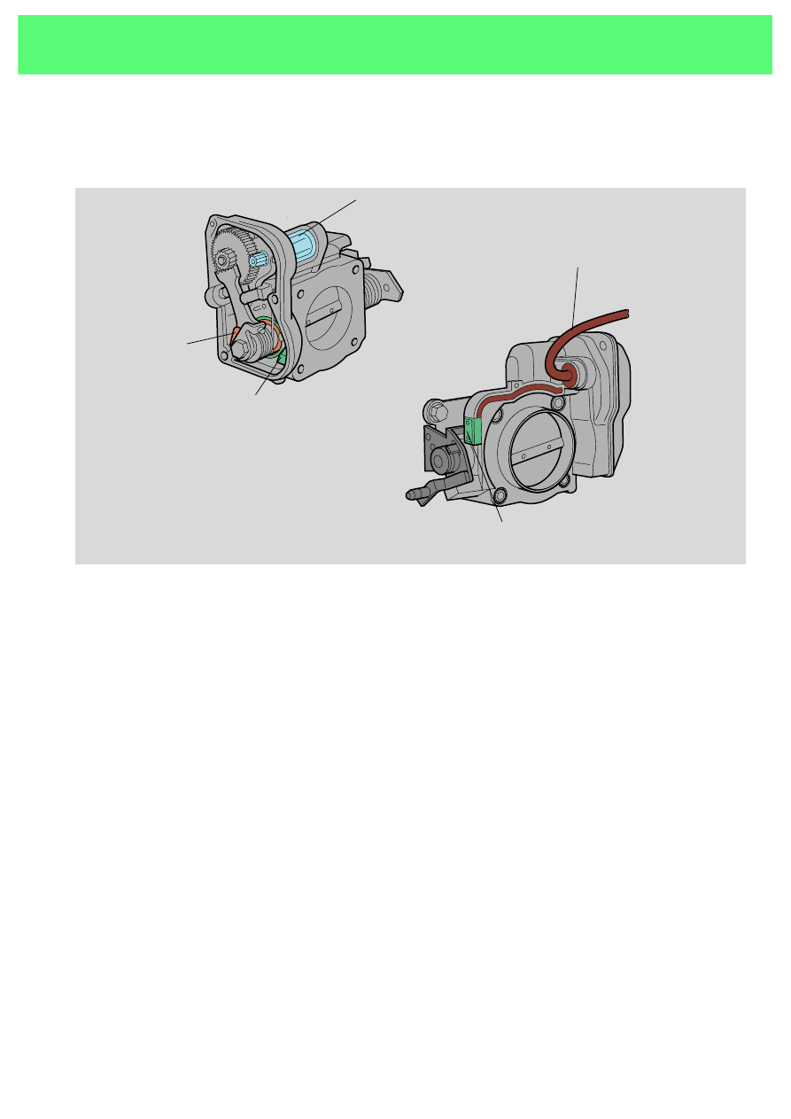
The throttle valve control unit J338
189-27
Electrical supply
Throttle valve
positioner -
potentiometer G88
Throttle valve
potentiometer
G69
Idling switch F60
Throttle valve positioner V60
Construction:
The throttle valve control unit has the same
construction as the throttle valve control unit
described in SSP 173.
The only difference is that the idling switch is
on the exterior and on the opposite side.
Signal processing:
The throttle valve control unit recognises the
position of the throttle valve positioner and
changes it until the desired idling speed has
been reached.
In this way the idling speed can be set for
different engine loads.
34
Consequences of signal failure in throttle
valve control unit:
An emergency speed is mechanically set by
means of a spring
Additional function: warming up the catalytic
converter
The catalytic converter should be heated up as
quickly as possible to operating temperature.
Therefore when the engine is cold the control
unit raises the idling speed for 25 seconds
after start up to 1150 1/min.
1150
:25
189-46
"Error message" self diagnosis:
Electrical switching:
5, 14 control for throttle valve positioner V60
17
input signal idling switch F60
8
input signal throttle valve positioner -
potentiometer G88
6
output signal of potentiometer
15
input signal throttle valve potentiometer
9
sender earth
15
5
14
17
8
6
9
V60
F60
G88
M
G69
J220
(T17a)
31
Idling switch F60
implausible - closed
loose contact
implausible - open
189-28
Throttle valve potentiometer G69
signal too large
signal too small
loose contact
Throttle valve positioner - potentiometer G88
signal too large
signal too small
loose contact
Idling control

35
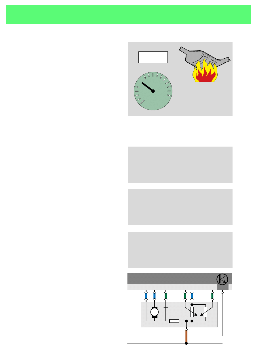
The 3-way catalytic converter
reduces the level of harmful substances
-
carbon monoxide (CO)
-
hydrocarbon (HC)
-
nitrogen oxide (NO
x
)
in the exhaust gas.
It is contained in a stainless steel housing.
189-49
Operating temperature:
The catalytic converter cuts in at a
temperature of roughly 250
°C.
The ideal operating temperature is between
400
° and 800°C. These temperatures ensure
-
high level reduction of harmful emissions
-
long life.
At temperature above 1400
°C the ceramic core
melts. This would destroy the catalytic
converter.
Exhaust gas cleaning
36
189-50
exhaust flap
vacuum line
valve for exhaust flap N220
pressure container
catalytic converter
silencer
exhaust stream
Schematic diagram of
exhaust flap control
The exhaust flap
Function:
The exhaust flap, when closed, channels the
stream of exhaust gases directly to the
catalytic converter so that it can reach its
operating temperature. This happens at start
up, during idling and part load.
Function:
The engine control unit operates the exhaust
flap via the exhaust flap valve and the
pressure container.
If problems arise the exhaust flap
should be given a visual check. See
repair manual.
Consequence of signal failure:
The flap is open, the catalytic converter cannot
overheat.
When the flap is closed the stream of hot
exhaust gases is channelled directly from the
engine to the catalytic converter.
When the flap is open the exhaust gas is
channelled to the catalytic converter via the
silencer. The gases cool down slightly in the
silencer, yet are still within the operating
temperature of the catalytic converter.
Exhaust gas cleaning

37
Lambda control
This supports the function of the catalytic
converter by altering the quantity of fuel
injected depending on the oxygen content of
the exhaust. This is to ensure that the exhaust
can be cleaned optimally in the catalytic
converter.
Conditions for lambda control:
•
coolant temperature > 60
°C
•
idling of part load
•
no overrun cut-off
Electric circuit:
6, 7 Lambda probe G39 input signal
16
Control of lambda probe heating
3
Control of exhaust flap N220
J220
3
16
7
6
N220
G39
Z19
(T17b)
31
Lambda probe G39
This measures the oxygen content of the
exhaust thereby making lambda control
possible. This value is then passed to the
control unit as a voltage signal.
The lambda control is not possible until an
operating temperature of 300
°C has been
reached.
To aid this, electric heating is integrated in the
probe.
The optimum temperature is around 600
°C.
The reaction times for the lambda probe are
shortest at this temperature.
189-75
38
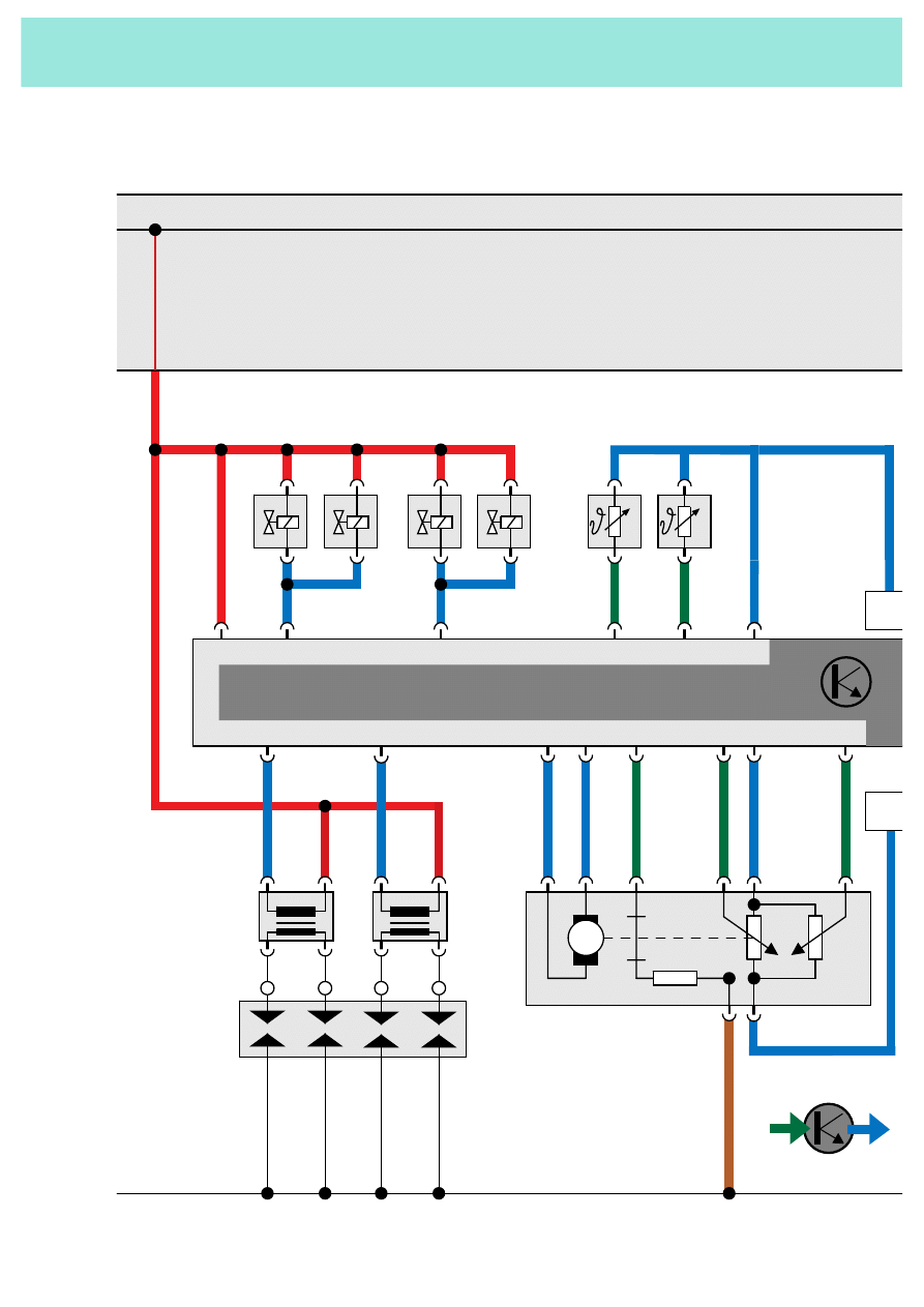
X
1
4
3
2
4a
4b
4a
4b
Q
P
N222
N223
15
1
15
1
5
14
17
8
6
15
V60
F60
G88
M
G69
10
30
15
2
N30
N33
J22
4
16
G42
7
G62
9
13
N31
N32
11
(T17a)
(T17a)
IN
OUT
X
Functional plan

39
J17
N80
G6
M
30
15
N221
10
15
13
14
A
B
C
S81
8
3
17
16
7
6
G28
9
5
1
N220
G39
Z19
(T17)
(T17)
31
1
2
(T2)
189-60

40
F60
idling switch
G6
fuel pump
G39
lambda probe
G42
intake air temperature sender
G62
coolant temperature sender
G69
throttle valve potentiometer
G88
throttle valve positioner potentiometer
G28
engine speed sender
J17
fuel pump relay
J220
Motronic control unit
J338
throttle valve control unit
N30
injection valve cylinder 1
N31
injection valve cylinder 2
N32
injection valve cylinder 3
N33
injection valve cylinder 4
N80
valve for ACF
N220
valve for exhaust flap
N221
resistor for ignition map balancing
resistor
N222
ignition transformer for cylinders 1
and 4
N223
ignition transformer for cylinders 2
and 3
P
spark plug plug
Q
spark plugs
V60
throttle valve positioner
Z19
heating for lambda probe
A
self diagnosis
B
engine speed signal
C
input signal road speed
input signal
output signal
supply voltage
earth connection

42
The self diagnosis system
monitors
-
the sensor signals
-
the control of the actuators
-
and the control unit.
If the control unit detects an error it calculates
a substitute valve from other signals and
provides emergency operation functions.
Every detected error is stored in the control
unit.
If the control unit detects an error
it calculates a substitute valve
from other signals and provides
emergency operation functions.
Every detected error is stored in
the control unit.
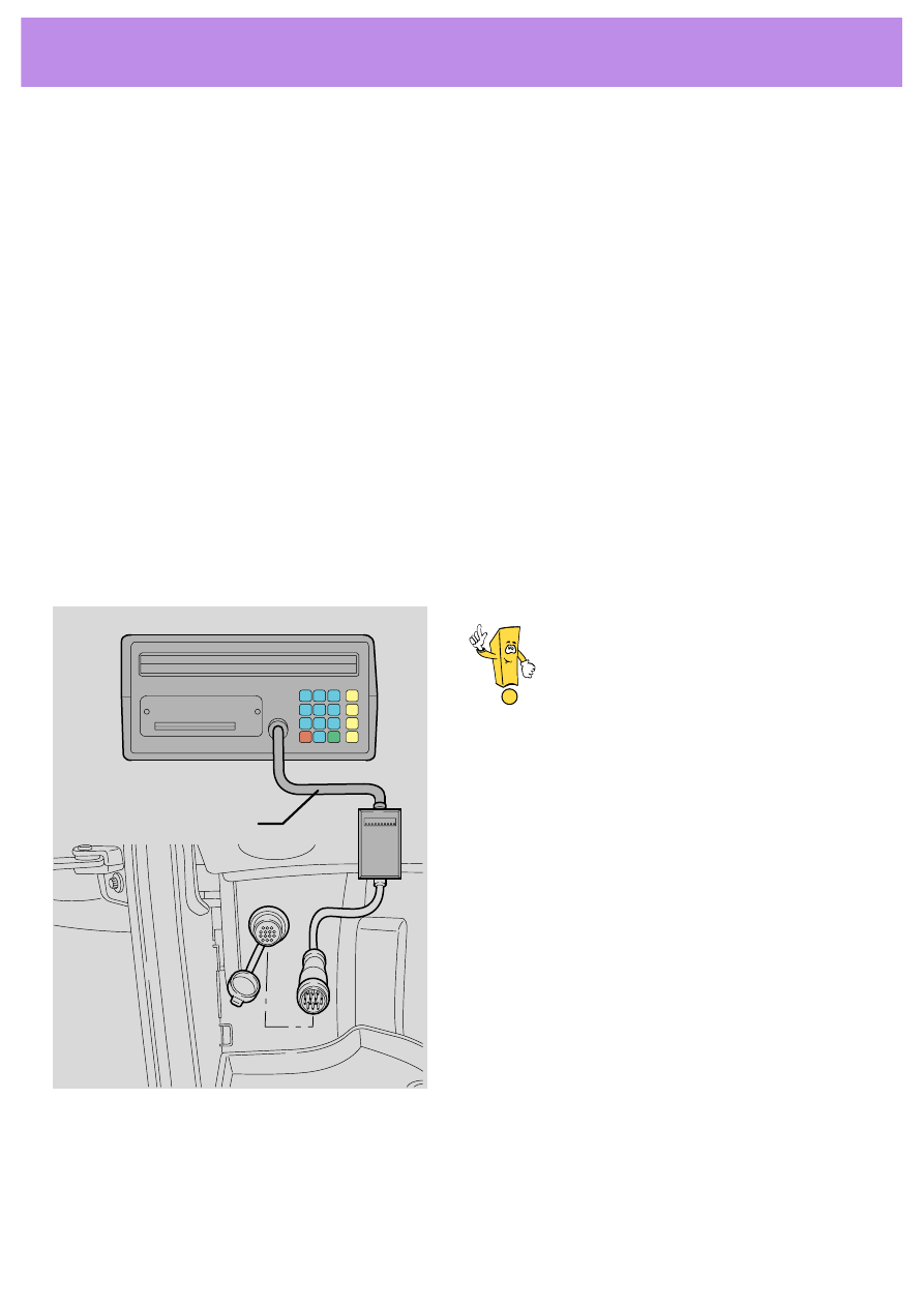
V.A.G 1551
1 2 3
4 5 6
7 8 9
C 0 Q
V.A.G 1551/5
189-63
The following functions are available:
01 - control unit version inquiry
02 - error memory inquiry
04 - basic setting
05 - delete error memory
07 - actuator diagnosis
08 - read measured data block
Self diagnosis
43
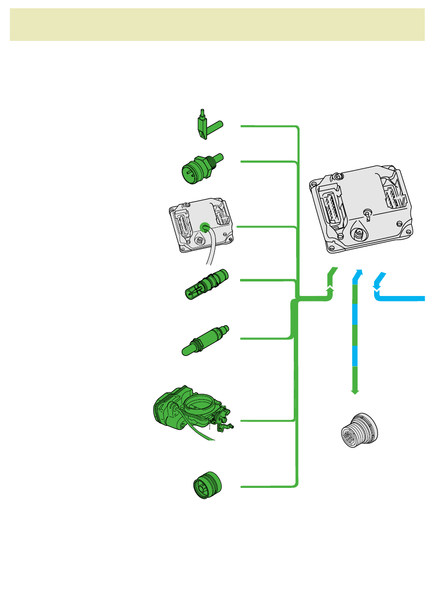
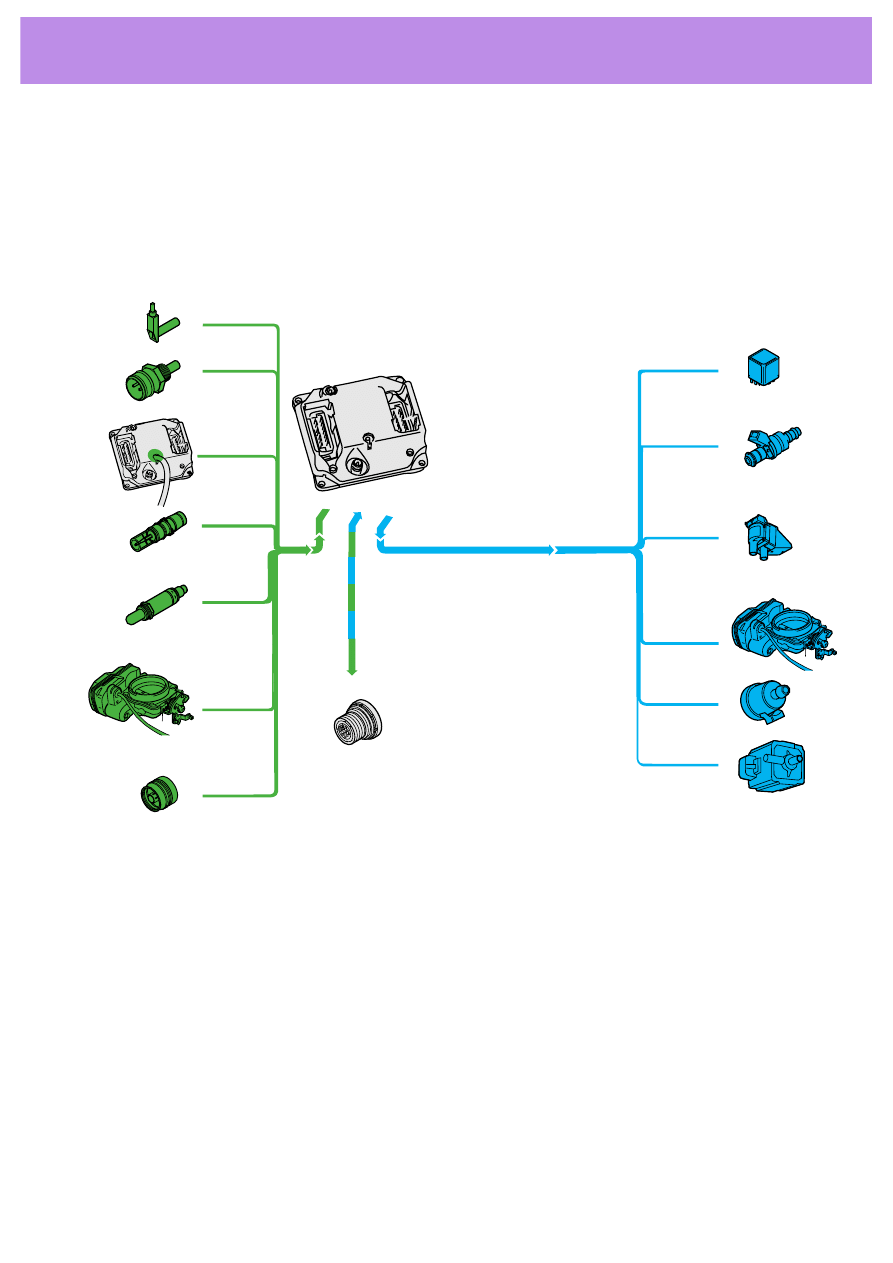
Function 02 - Error memory inquiry
The colour coded sensors and actuators are
monitored by the self diagnosis.
189-64
The self diagnosis system distinguishes
between the following errors:
-
errors which are constantly present
-
errors which are present for longer than
3 seconds
-
loose contact errors which arise more than
5 times during a journey.
If an error does not occur for 19 journeys it is
then deleted.
If the engine control unit is removed or the
battery is disconnected the error messages are
lost.

44
Function 04 - Basic setting
The control unit activates the throttle valve
control unit. It registers the increase in the
current of the servo-motor and the resistance
value of the throttle valve positioner
potentiometer. It stores these values.
There are two possible ways to activate the
basic setting:
- turn on the ignition and wait for 10 seconds
or
- select function 04 on the V.A.G. 1551 and pro-
ceed following the instructions.
In both cases the accelerator pedal
must not be depressed.
Function 07 - actuator diagnosis
-
tank venting valve N80
-
exhaust flap N220 and
-
the exhaust flap after start up
are activated.
Self diagnosis
45
Function 08 - read the data table
Function 08 - read the data table.
189-66
46
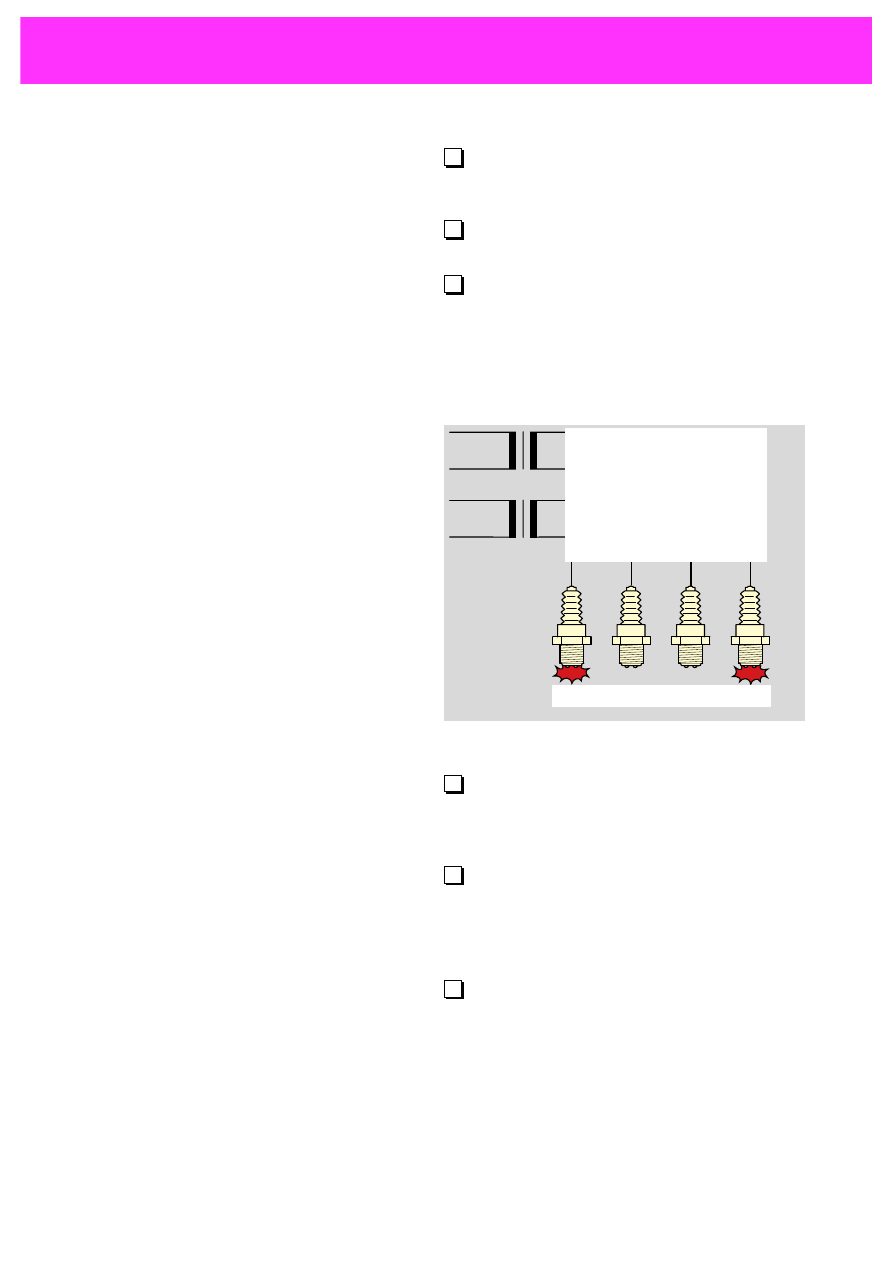
... the start of the injection phase needs to
be adjusted.
... nothing needs to be done.
... the ignition map balancing resistor in
the control unit needs to be removed.
A
B
C
If an ignition coil develops a fault the
injection is cut on the appropriate injec-
tion valves.
The control unit measures the current flo-
wing between the ignition coil and the
spark plugs in order to monitor the secon-
dary circuit.
The current and voltage are monitored in
the circuit between the control unit and
the spark plugs.
A
B
C
1
2
3
4
N222
N223
Self check
1.
To run the engine on ROZ 91 ...
2.
Draw in the link between the spark plugs
and the ignition coils.
3.
Which of the following statements are cor-
rect? Tick the right answers.
47
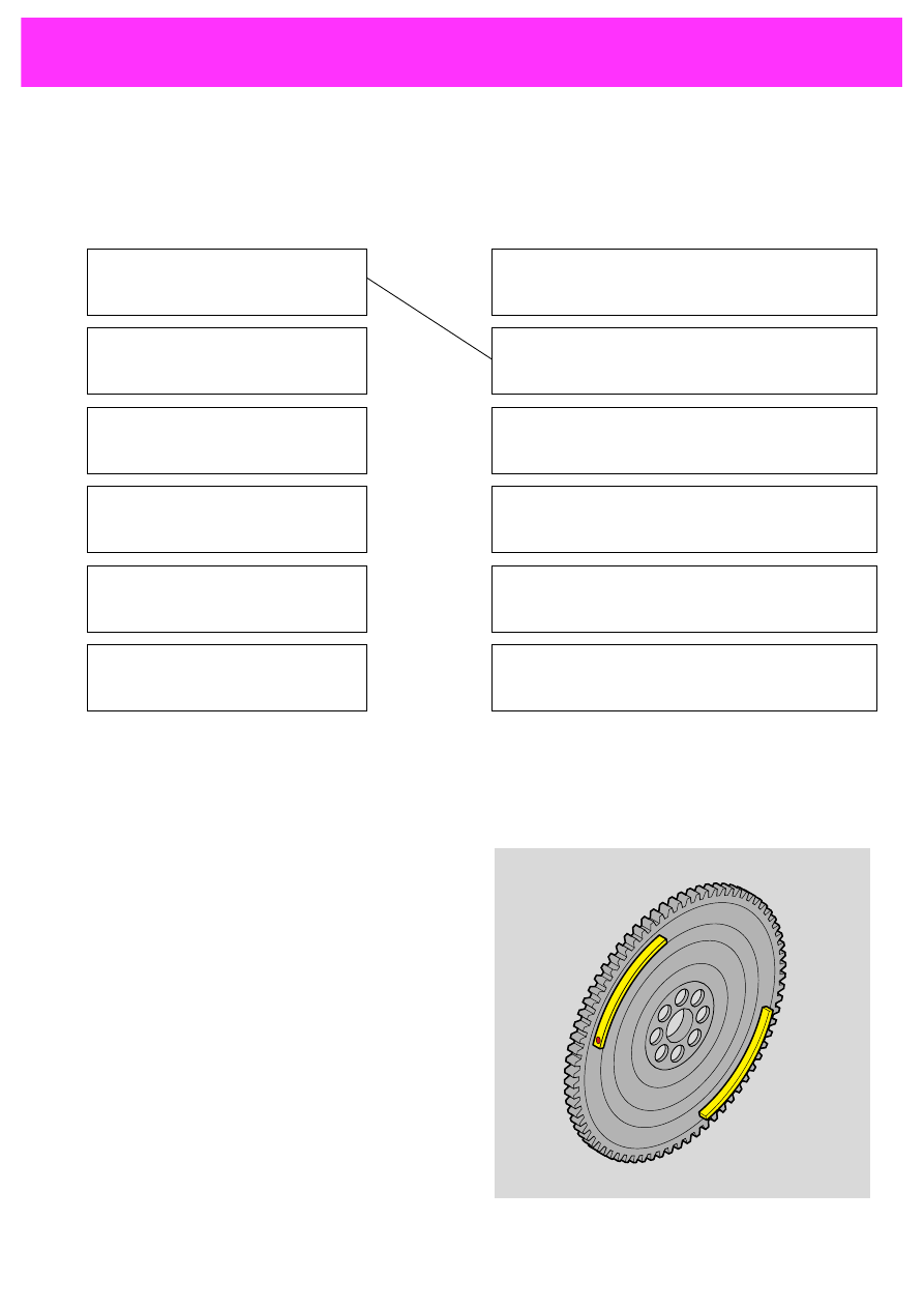
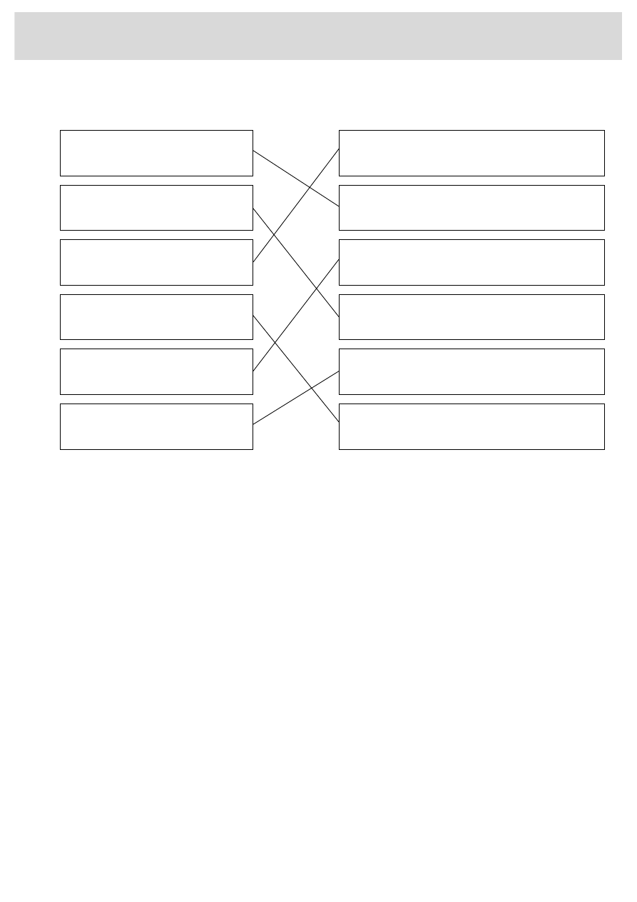
4.
Decide which statements belong together.
Connect them up.
5.
Complete the following text.
Segments are mounted on the
____________________________ which are detec-
ted by the ____________________________. A
____________________________ is attached to
each segment. The
____________________________uses this to
distinguish whether the signal belongs to
___________________ and ______ or to
___________________ and ______ .
After starting the ignition
When moving from overrun to
acceleration
On starting from cold
When the engine is cold
With full load
In overrun
the injection quantity is increased.
the advance angle is set to " Delayed" for
roughly 25 seconds.
the quantity of fuel in the mixture is
increased.
the advance is briefly set to "delayed".
the fuel supply is cut by the injection valves
being switched off.
the idling revs are increased for 25 seconds
after start up to 1150 1/min.
48
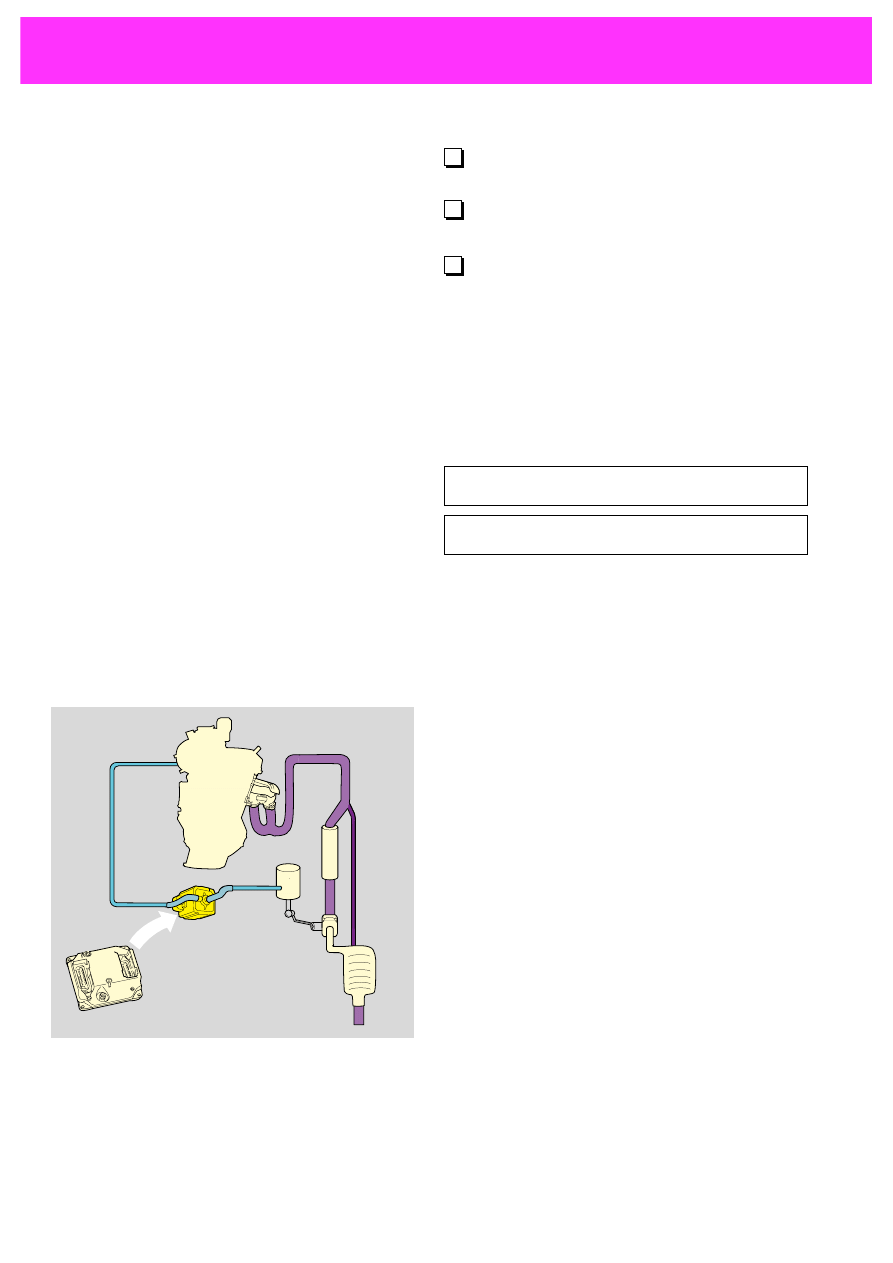
...be found by reading the error memory.
...not be found while it is still installed.
...be found by checking the values in the
data list.
A
B
C
8.
Complete the following text.
The engine control unit activates the flap via
the ____________________________ and the
____________________________ .
When the flap is ____________________________
the hot stream of exhaust gas is channelled
directly from the engine to the catalytic
converter and accelerates the heating up of
the converter to its working temperature of
roughly 400
°C.
When the flap is ____________________________
the exhaust stream is channelled to the cataly-
tic converter via the silencer. In this case the
gas is so hot that even after being cooled in
the ____________________________ it is still hot
enough for the working temperature of the
catalytic converter to be reached.
Self check
6.
An error in the coolant temperature sen-
der can...
7.
Give two factors which protect or support
the function of the catalytic converter:

49
Notes
50
Answers to self check questions on page 13:
1.:
for cooling
2.:
The
fuel pump sucks up the fuel, pumps it
via the
fuel filter through the header to the
injection valves.
The
diaphragm pressure controller controls
the fuel pressure in the header depending on
the intake
manifold pressure and channels
excess fuel back to the
fuel tank.
Answers to self check questions from page 43:
1.: c
2.:
3.: a, c
1
2
3
4
N222
N223
51
5.: Segments are mounted on the flywheel
which are detected by the
engine speed
sender. A permanent magnet is attached to
each segment. The
control unit uses this to
distinguish whether the signal belongs to
cylinders 1 and 4 or to cylinders 2 and 3.
6.: a
7.: e.g.
- exhaust flap control
- heating the catalytic converter after start up
8.: The engine control unit activates the flap
via the
exhaust flap valve and the pressure
container.
When the flap is
closed the hot stream of
exhaust gas is channelled directly from the
engine to the catalytic converter and accelera-
tes the heating up of the converter to its wor-
king temperature of roughly 400
°C.
When the flap is
open the exhaust stream is
channelled to the catalytic converter via the
silencer. In this case the gas is so hot that
even after being cooled in the silencer it is still
hot enough for the working temperature of the
catalytic converter to be reached.
4.:
Please note that other combinations may also be correct.
after starting the ignition
when moving from overrun to
acceleration
on starting from cold
when the engine is cold
with full load
in overrun
the injection quantity is increased.
the advance angle is set to "Delayed" for
roughly 25 seconds.
the quantity of fuel in the mixture is
increased.
the advance is briefly set to "delayed".
the fuel supply is cut by the injection valves
being switched off.
the fuel supply is cut by the injection valves
being switched off.

Only for internal use.
© VOLKSWAGEN AG, Wolfsburg
All rights reserved
640.2810.08.20
Published: 05/96
❀ This paper has been made from
paper which has not been
bleached using chlorine.
Wyszukiwarka
Podobne podstrony:
Self Study Programme 351 Common rail fuel injection system fitted in the 3 0l V6 TDI engine
Self Study Programme 388 4 2L V8 4V FSI engine
Self Study Programme 279 2 0L 110kw with petrol direct injection FSI
Self Study Programme 376 5 2 litre V10 FSI engine
Self Study Programme 365 4 2L V8 with common rail
Self Study Programme 431 Audi RS 6
Self Study Programme 17 Octavia convenience electronic system
Self Study Programme 396 Lane change assist
Self Study Programme 276 Phaeton automatic proximity control
Self Study Programme 280 Phaeton auxiliary heater top c and top z
Self Study Programme 288 Audi A8 03 distributed functions
Self Study Programme 398 Audi lane assist
Sisson Google Secrets How to Get a Top 10 Ranking On the Most Important Search Engine in the World
Low Temperature Differential Stirling Engines(Lots Of Good References In The End)Bushendorf
Nukariya; Religion Of The Samurai Study Of Zen Philosophy And Discipline In China And Japan
Multicenter study for Legg Calvé Perthes disease in Japan
Making petrol engine pistons id Nieznany
32 Audi A6 Cruise control system petrol engines
Generics in the Java Programming Language
więcej podobnych podstron