
365
All rights reserved. Technical
specifications subject to
change without notice.
Copyright
AUDI AG
N/VK-35
Service.training@audi.de
Fax +49-7312/31-88488
AUDI AG
D-74172 Neckarsulm
Technical status: 10/05
Printed in Germany
A05.5S00.18.20
Audi 4.2 l V8 TDI with
Common Rail Injection System
Self-Study Programme 365
Vorsprung durch Technik
www.audi.co.uk
Service Training
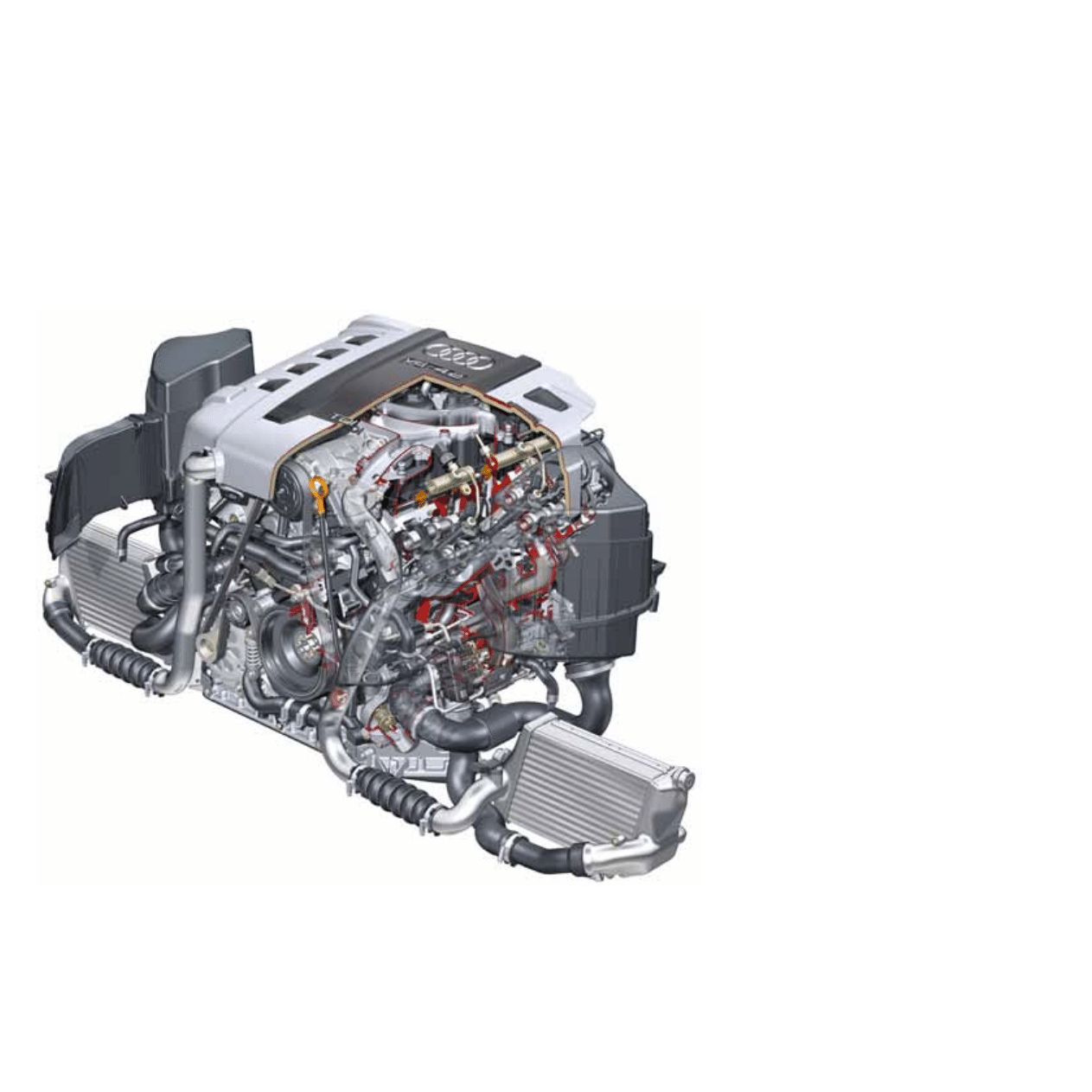
365_001
In 1999, the 3.3 l A8 (1994) was installed for the first time with a V8 TDI engine, followed in the new A8 by an
improved 4.0 l chain-driven engine.
With the 4.2 l V8 TDI engine, the vee engine family with its 90° cylinder angle, 90 mm cylinder spacing and output-
end chain drive has undergone a complete overhaul.
The 4.2 l powerplant represents a logical evolution of the V8 TDI with 240 kW of power and 650 Nm of torque.

Differences between the 4.0 l and 4.2 l V8 TDI engines . . . . . . . . . . . . . . . . . . . . . 4
Performance features . . . . . . . . . . . . . . . . . . . . . . . . . . . . . . . . . . . . . . . . . . . . . . . . . 5
Cranktrain . . . . . . . . . . . . . . . . . . . . . . . . . . . . . . . . . . . . . . . . . . . . . . . . . . . . . . . . . . . . 6
Cylinder head and valve gear . . . . . . . . . . . . . . . . . . . . . . . . . . . . . . . . . . . . . . . . . . . 9
Chain drive . . . . . . . . . . . . . . . . . . . . . . . . . . . . . . . . . . . . . . . . . . . . . . . . . . . . . . . . . . 11
Oil circulation system . . . . . . . . . . . . . . . . . . . . . . . . . . . . . . . . . . . . . . . . . . . . . . . . . 12
Crankcase breather system . . . . . . . . . . . . . . . . . . . . . . . . . . . . . . . . . . . . . . . . . . . . 14
Cooling system . . . . . . . . . . . . . . . . . . . . . . . . . . . . . . . . . . . . . . . . . . . . . . . . . . . . . . . 15
Air intake . . . . . . . . . . . . . . . . . . . . . . . . . . . . . . . . . . . . . . . . . . . . . . . . . . . . . . . . . . . . 16
Exhaust gas recirculation system . . . . . . . . . . . . . . . . . . . . . . . . . . . . . . . . . . . . . . 19
Fuel system . . . . . . . . . . . . . . . . . . . . . . . . . . . . . . . . . . . . . . . . . . . . . . . . . . . . . . . . . . 22
System overview . . . . . . . . . . . . . . . . . . . . . . . . . . . . . . . . . . . . . . . . . . . . . . . . . . . . . 28
CAN data bus interfaces. . . . . . . . . . . . . . . . . . . . . . . . . . . . . . . . . . . . . . . . . . . . . . . 30
Exhaust system with diesel particulate filter . . . . . . . . . . . . . . . . . . . . . . . . . . . . . 31
Special tools . . . . . . . . . . . . . . . . . . . . . . . . . . . . . . . . . . . . . . . . . . . . . . . . . . . . . . . . . 32
4.2 l V8 TDI engine with common rail injection system
Table of contents
The Self-Study Programme contains information on the design and function of new models,
new automotive components or new technologies.
The self-study programme is not intended as a workshop manual!
All values given are only intended to help explain the subject matter and
relate to the software version applicable when the SSP was compiled.
Use should always be made of the latest technical literature when performing maintenance and repair work.
Note
Reference
4
365_001
4.2 l V8 TDI engine with common rail injection system
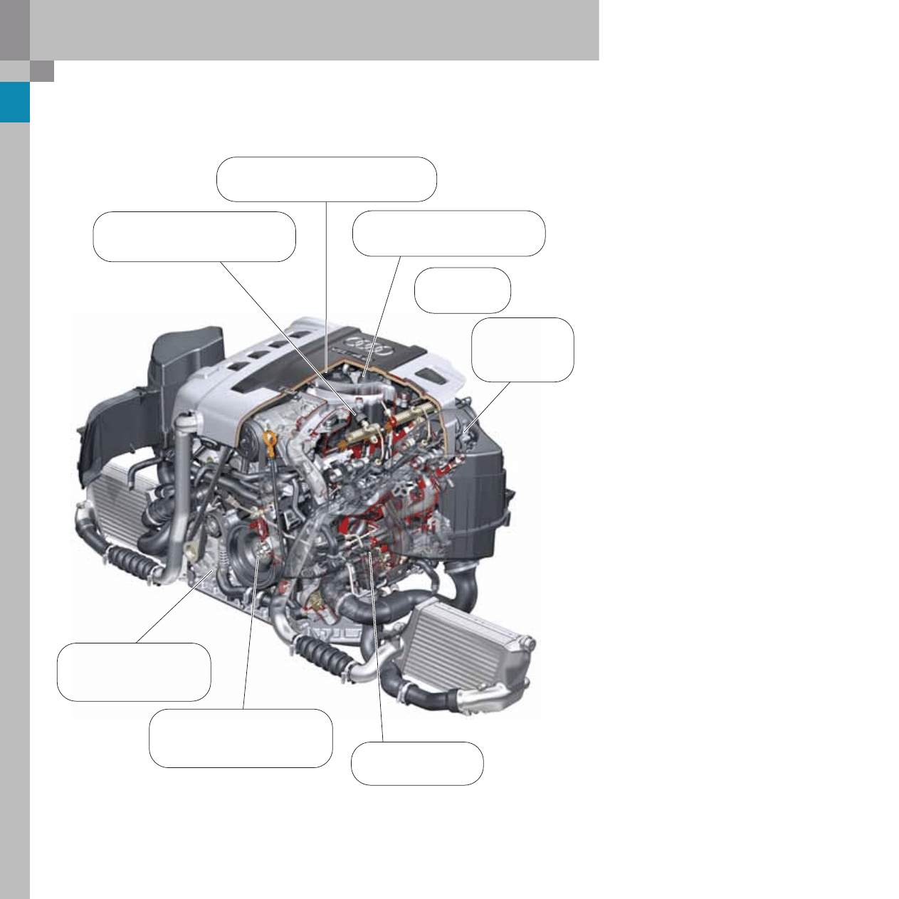
Differences between the 4.0 l and 4.2 l V8 TDI engines
Optimised exhaust
turbocharger
Crankcase with 90 mm
cylinder spacing and
83 mm cylinder bore
Belt drive with torsion vibration
damper, freewheel and
additional stabilising roller
Common rail injection system
With third-generation piezoelectric
injectors
Switchable, exhaust gas recirculation
cooler with water through-flow
Exhaust gas recirculation system
with electrical actuators
Cast exhaust
manifold
Adoption of
cylinder head
concept from
the 3.0 l V6 TDI
5
365_012
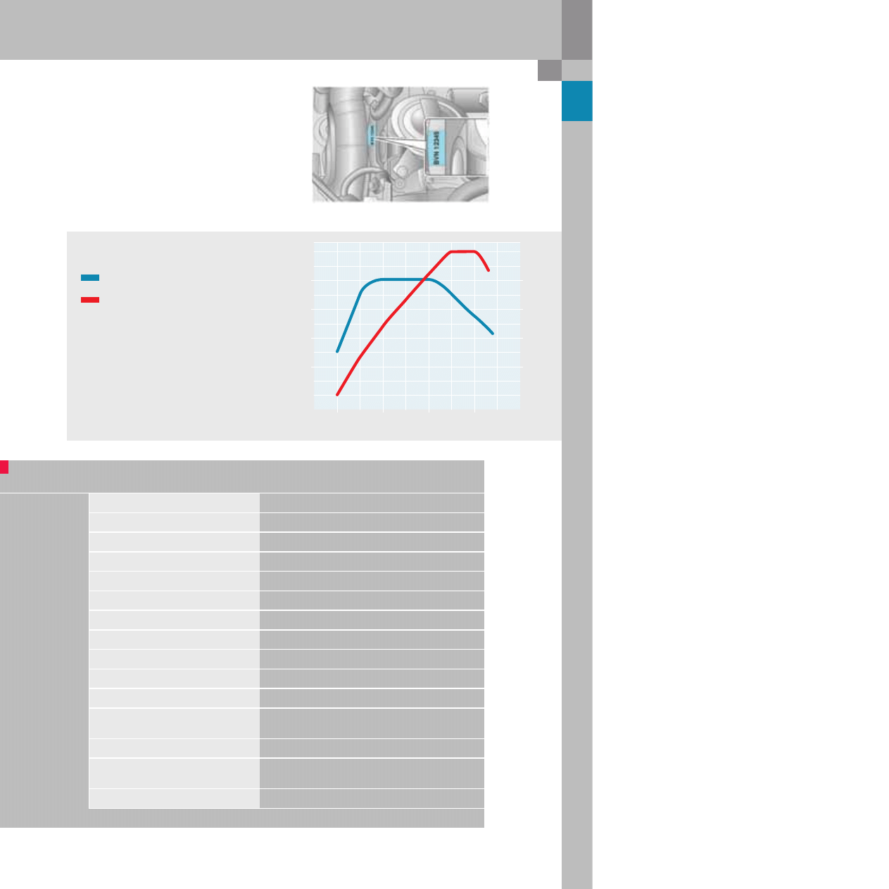
Specifications
Engine code
BVN
Type of engine
V8 diesel engine 90° vee angle
Displacement
in cm
3
4134
Max. power output
in kW (bhp)
240 (326)
Max. torque
in Nm
650 at 1600 to 3500 RPM
Bore
in mm
83
Stroke
in mm
95.5
Compression ratio
16,4 : 1
Cylinder spacing
in mm
90
Firing order
1–5–4–8–6–3–7–2
Engine weight
in kg
255
Engine management
Bosch EDC-16CP+ common rail injection system
up to 1600 bar with 8-port piezoelectric injectors
Exhaust gas recirculation system
Water-cooled EGR
Exhaust emission control
Two oxidising catalytic converters,
Two maintenance-free diesel particulate filters
Exhaust emission standard
EU IV
160
80
550
Nm
350
250
450
750
40
240
kW
1000
2000
3000
4000
5000
120
Performance features
Engine code, torque and power output
The engine number is located on the end face of cyl-
inder bank II, left.
Engine speed in RPM
Torque/power curve
Max. torque in Nm
Max. power output in kW
6
365_003
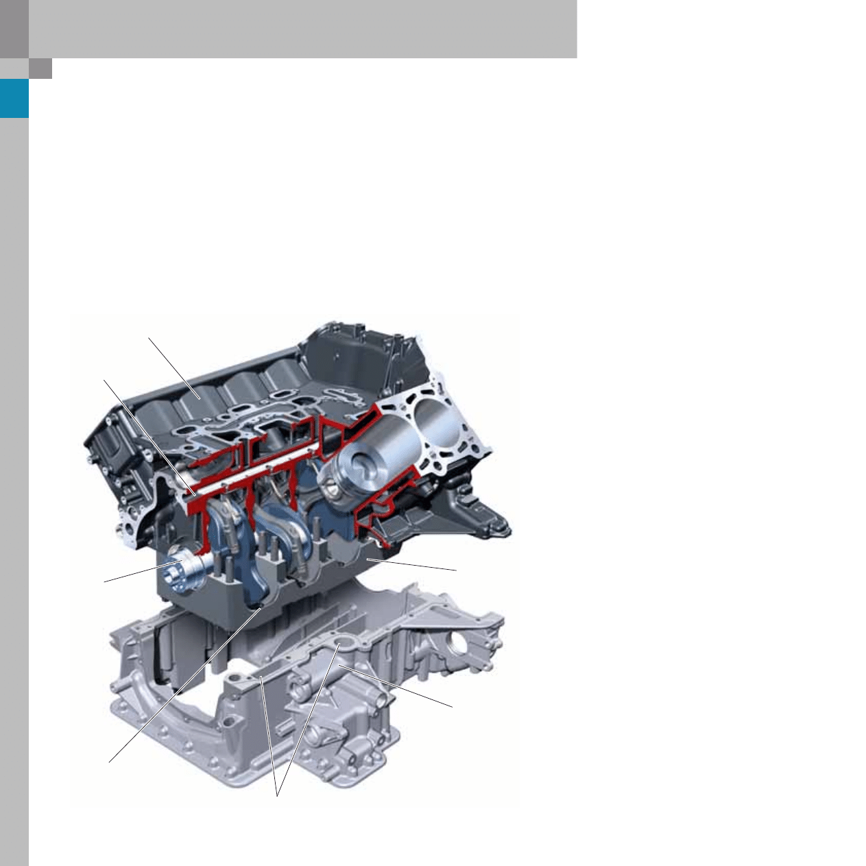
4.2 l V8 TDI engine with common rail injection system
By using a compact design it was possible to
achieve torque-free balancing of the cranktrain
using the crankshaft's counterweights alone.
An optimum balance was achieved with the help
of additional weights, which are attached to the
vibration damper and the driver plate. The deep
aluminium oil pan is to a great extent isolated from
crankshaft drive vibration, which has a positive
effect on acoustic quality.
The main bearing frame contour serves an addi-
tional function. It acts as a "baffle plate" in the
crankshaft counterweight and con-rod areas.
Thus, draining oil is not distributed throughout the
engine block, but is collected directly and drained
off.
Crankcase
Crankshaft
Aluminium oil pan
Bearing frame
Main oil port
Oil return channels
These edges function
as baffle plates
Crankshaft drive
The crankcase with 90 mm cylinder spacing is made
of vernicular graphite (GJV 450) and, like the 4.0 l V8
TDI engine, is split at the centre of the crankshaft
and bolted to a sturdy crankshaft bearing frame.
The weight of the engine block was reduced by
approximately 10 kg by utilising the material's spe-
cial properties.
The forged steel crankshaft is made of 42 Cr Mo S4
and cranked in such a way that free first and second
order moments are avoided. The crankshaft is runs
in five bearings in the crankcase, and the radii of the
con-rod bearing journals are rolled for strength rea-
sons.
7
365_011a
365_011b
365_025
365_016
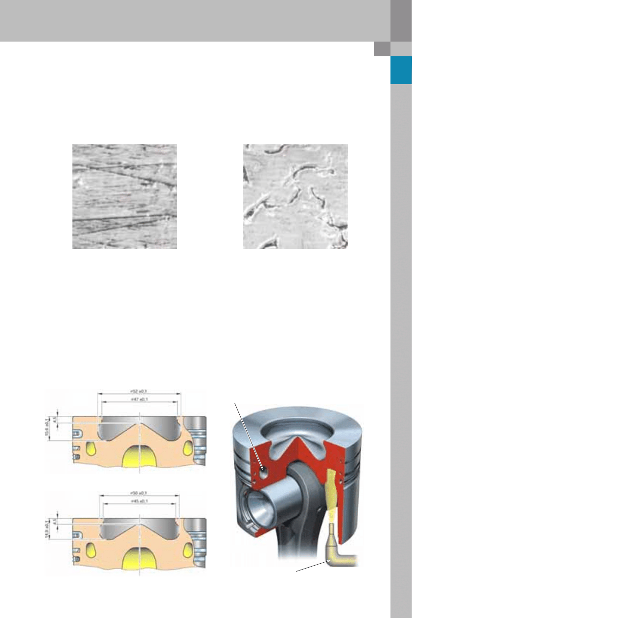
The UV laser imaging honing process used to manu-
facture the 3.0 l V6 TDI engine has also been used
for this engine.
without laser imaging
with laser imaging
The piston has an annular cooling duct to reduce
the temperature of the piston ring zone and the
recess rim.
An oil spray nozzle continuously sprays the oil into
the annular oil cooling duct in order to cool the pis-
ton crown.
This process helps to reduce oil consumption. The
antifriction properties of the cylinder liners were
significantly improved in this way.
Annular oil cooling duct
Oil spray nozzle
Piston
Designed as a recessed-head type piston, the piston
has a higher recessed head with a larger diameter
which reduces the engine's compression ratio from
17.3 : 1 to 16.4 : 1.
new
old
Comparison of piston crowns
8
365_017
365_035
4.2 l V8 TDI engine with common rail injection system
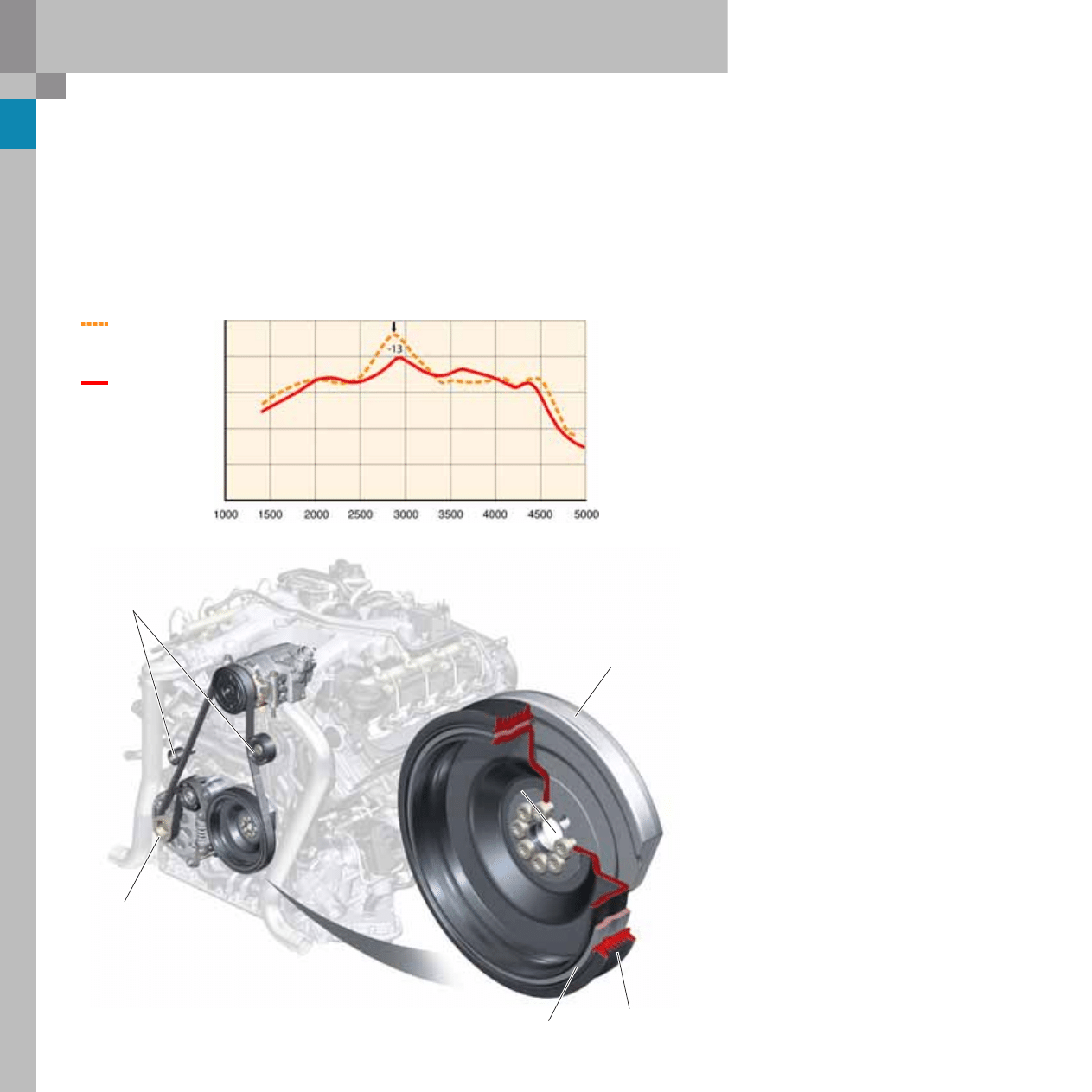
Crankshaft vibration damper
The 4.2 l V8 TDI engine is equipped with a torsion
vibration damper (old version with a belt vibration
damper with isolation of the poly vee belt track).
To dampen oly vee belt vibrations, which occur at
the different rates of acceleration of the piston dur-
ing the combustion process, a freewheel was
installed in the alternator and an additional stabilis-
ing roller was fitted.
Additional
stabilising rollers
Crankshaft
counterweight
Belt track
Rubber track
Freewheel on the alternator
The torsion vibration damper was designed to
reduce the torsional moments which occur in the
medium engine speed range by approximately 13 %
compared to a belt vibration damper. The result is
less load on the crankshaft and improved engine
acoustics. The new belt drive drives the alternator
and the air conditioner compressor.
Belt
vibration
damper
Torsion
vibration
damper
Engine speed in rpm
T
o
rsional moment, amplitude in Nm
9
365_004
365_023
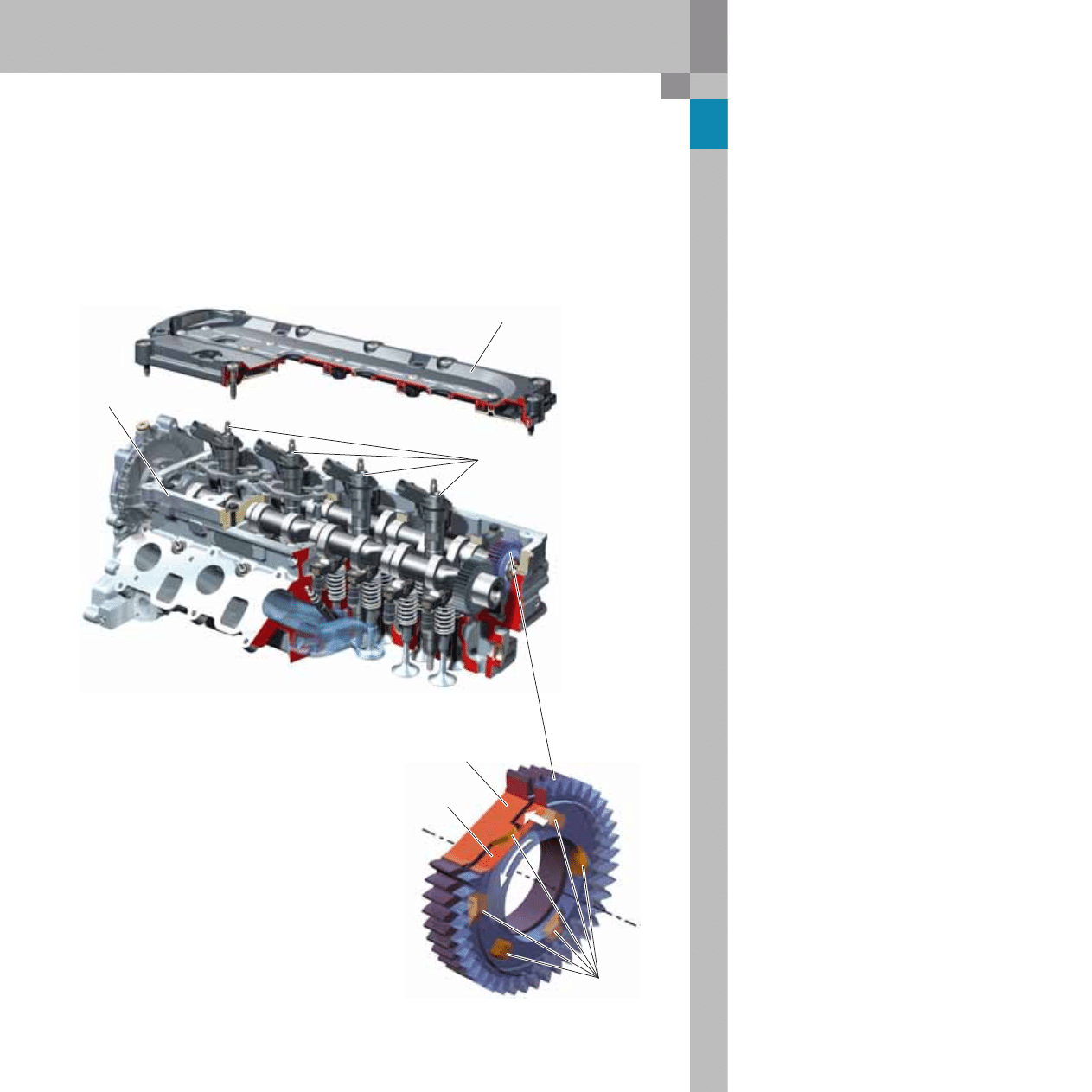
Cylinder head and valve gear
Derived from the 3.0 l V6 TDI engine, the cylinder
head is installed in combination with the following
components:
– four valves per cylinder,
– assembled camshafts,
– hydraulic valve lifters,
– roller cam followers and
– straight-cut/tensioned gears
Design
The spur gear of the exhaust camshaft is split into
two pieces in the cylinder head, left. The spur gear
of the intake camshaft gear is split into two pieces
in the cylinder head, right.
The wider part of the spur gear (rigid spur gear) is
attached securely to the camshaft.
There are six ramps on the front side of the spur
gear. The narrower part of the spur gear (moving
spur gear) moves in radial and axial directions.
Recesses for the six ramps are located on the back
of the spur gear.
Six ramps
Rigid
spur gear
Non-rigid
spur gear
The camshafts are held in place in the cylinder head
by a ladder frame with a flat sealing face. An acous-
tically isolated plastic cylinder head cover seals the
cylinder head off from the exterior.
Cylinder head cover
Ladder frame
Injectors arranged in the centre
of the combustion chamber
10
365_030
365_022
4.2 l V8 TDI engine with common rail injection system
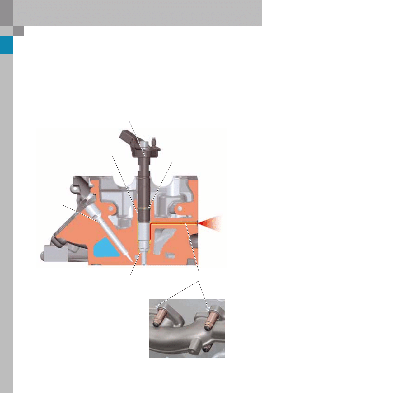
Breather duct in the cylinder head
If a leak occurs in the area of the copper injector
ring seal, the air is able to escape from the combus-
tion chamber through a duct due to the combustion
pressure of 165 bar. The breather duct is located
above the exhaust manifold in the cylinder head.
It prevents the excess pressure from travelling from
the combustion chamber via the crankcase breather
to the compressor side of the exhaust turbocharger
and possibly causing malfunctioning or damaging
the ring seals.
Ring seal to combustion chamber
Breather duct
The crankcase breather can be
accessed through the oil chamber
in the cylinder head
Piezoelectric injector
Glow plug channel
Ring seal
11
365_002
Reference
For further information, please refer to
SSP 325 - Audi A6 ´05 Engines and Trans-
missions.
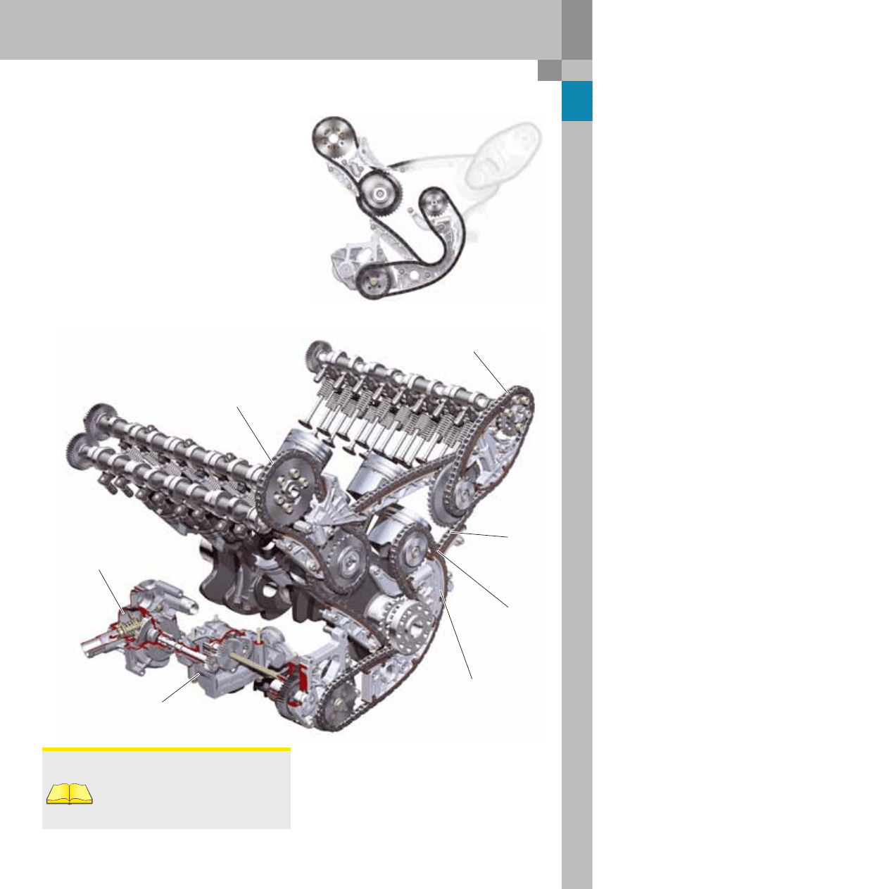
365_038
Chain drive
The chain drive adopted from the 4.0 l V8 TDI engine
has been optimised with regard to friction and
rotary oscillation. Part of the sliding rails in chain
drive D has been replaced by a new chain tensioner,
allowing the chain to be routed directly around the
intermediate shaft, thus shortening the length of
the chain.
Chain drive B has also been optimised, whereby the
number of teeth and the belt gear contact angle has
been increased and the chain guide has been
tapered.
Ancillary units such as the oil pump, hydraulic
pump and coolant pump are driven by chain drive D
via a gear module.
"New"
chain drive B
Chain drive C
Chain drive A
"New"
Chain drive D
Chain tensioner
for chain drive D
Chain drive D
Chain drive B
Coolant pump
Oil pump
12
365_043
4.2 l V8 TDI engine with common rail injection system
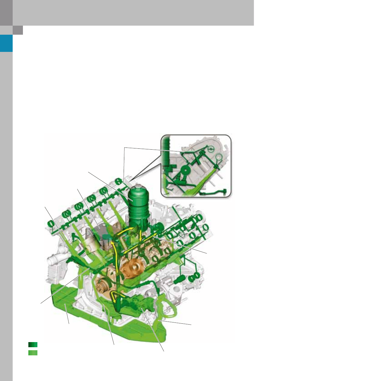
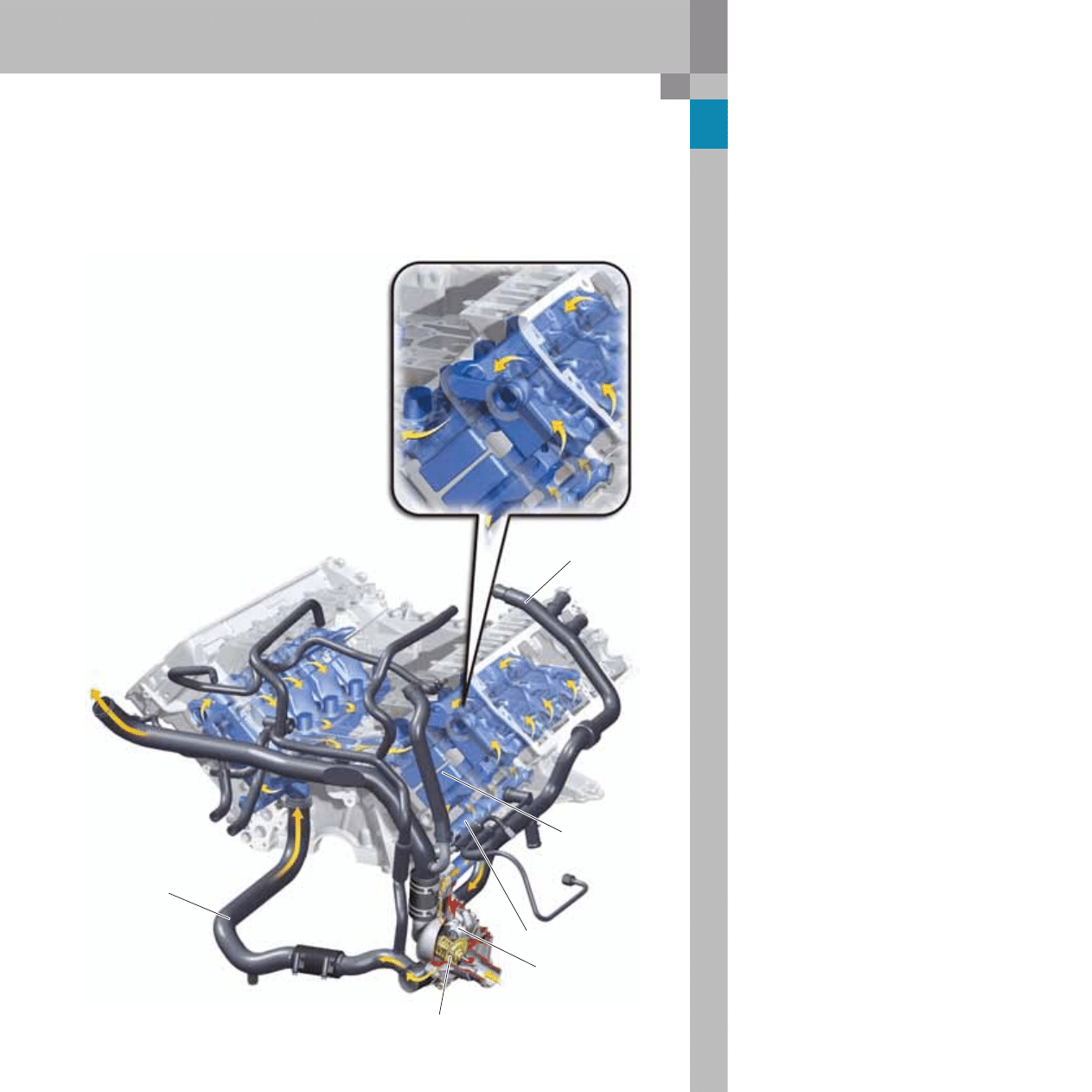
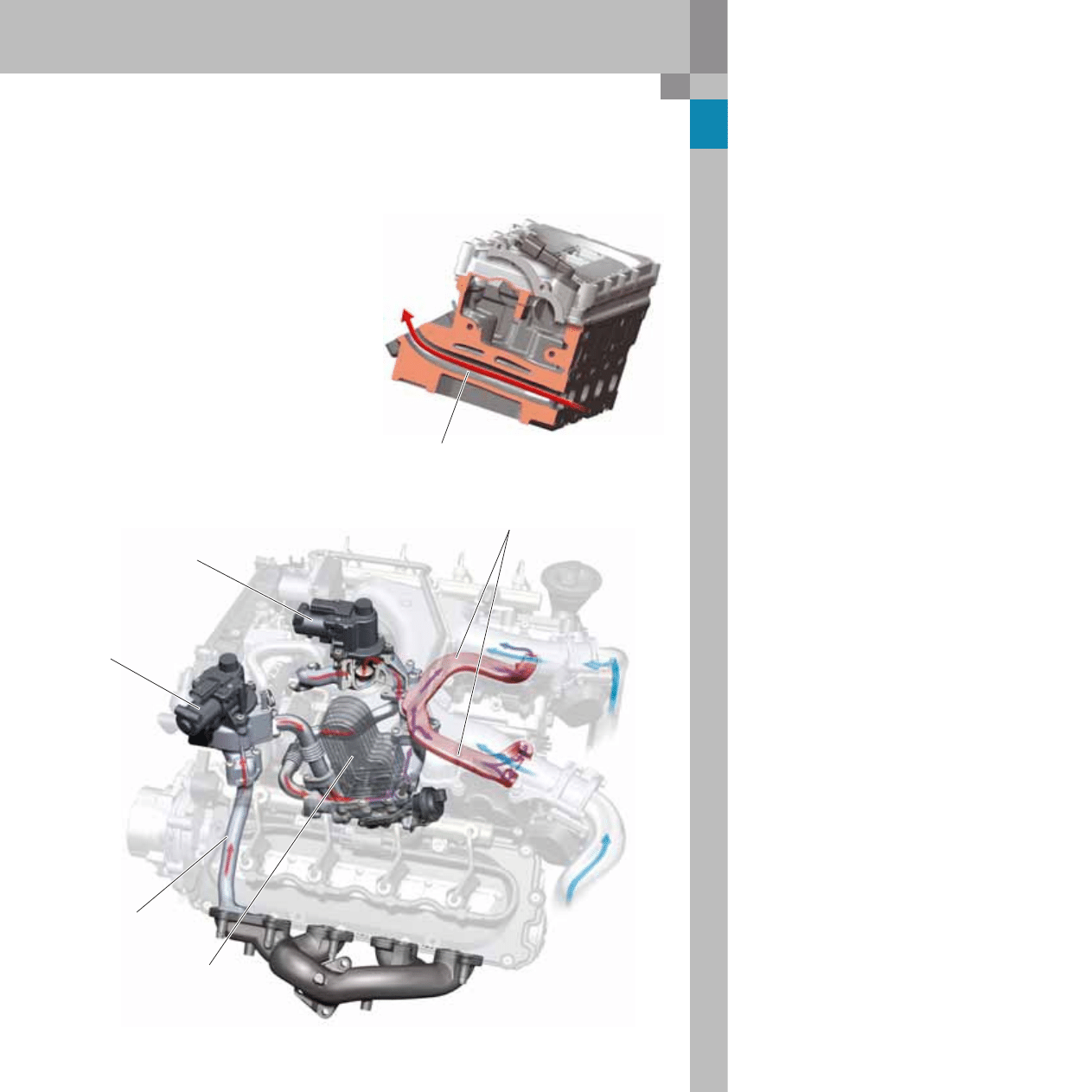
Oil circulation system
The oil circulation system, which is initially filled
with 11.5 l oil, begins in the gear oil pump. The oil
pressure relief valve is integrated in the oil pump.
From here, the oil flows to the water-oil cooler
installed in the engine's inner vee. The oil flows to
the oil filter along internal ducts in the oil filter
module. The oil filter module has a replaceable
paper filter for ease of servicing. When the paper fil-
ter is removed, the oil remaining in the housing
flows back into the oil pan through a drain valve.
After leaving the oil cleaner, the pressurised oil is
channelled into the main oil duct located in the
inner vee of the engine block.
Here, the lubrication points of the crankshaft, the
crankshaft bearings and the oil spray nozzle are
supplied with oil pressure.
Both turbochargers are supplied with pressurised
oil through additional outer oil lines from the main
oilway. The oil pressure flows into the cylinder
heads through risers with integrated restrictors,
and from here to the camshafts, the cam followers
and the hydraulic valve lifters.
A special feature is the vacuum pump lubrication
system, which is driven and supplied with oil by the
intake camshaft in the cylinder head, right. The
lubrication system is also supplied with pressurised
oil via its own oilway from the main oil duct.
Pressurised oil course
Oil return line
Oil filter module with inte-
grated crankcase breather
Main oil duct
Turbocharger return line
Oil pump
Oil return pipe from the
inner vee and the crankcase
breather
Oil pan
Oil supply for
turbocharger
Oil return from the
cylinder heads
Water-oil cooler
Rear view
Additional oil line from the oil
gallery to the vacuum pump
via the camshaft bearing
13
365_045
365_047
365_046
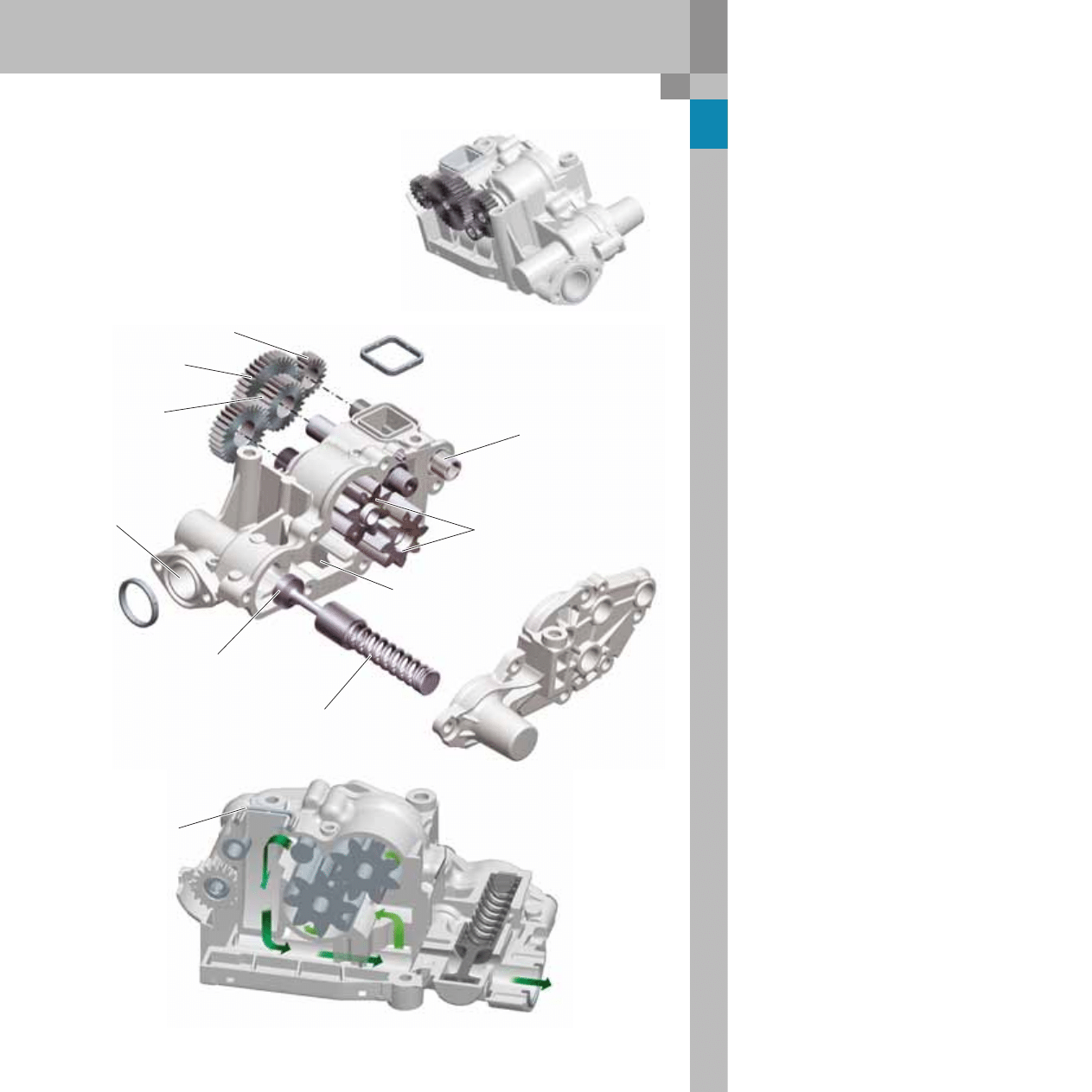
Oil pump
The gear oil pump is driven by a hexagonal shaft
connected to chain drive D via a gear module.
The oil pressure relief valve which the re-routes the
excess oil pressure (exceeding approx. 5.1 bar) to
the suction side of the oil pump.
An additional gear module on the oil pump drives
the coolant pump and the oil pump.
Drive gear from
chain drive D
Coolant pump drive
shaft output
Oil pump
drive gear
Oil pump gears
Compression spring
Overpressure regulator
control valve piston
Pressure side to
oil-water oil cooler
Intake side of oil pan
Oil pump cover,
high pressure side
Water pump
drive gear
Oil intake from
the oil pan via
an oil intake pipe
14
365_031
Intake manifold
outlet
To intake side of turbocharger
Oil return channel with
engine-internal oil pipe
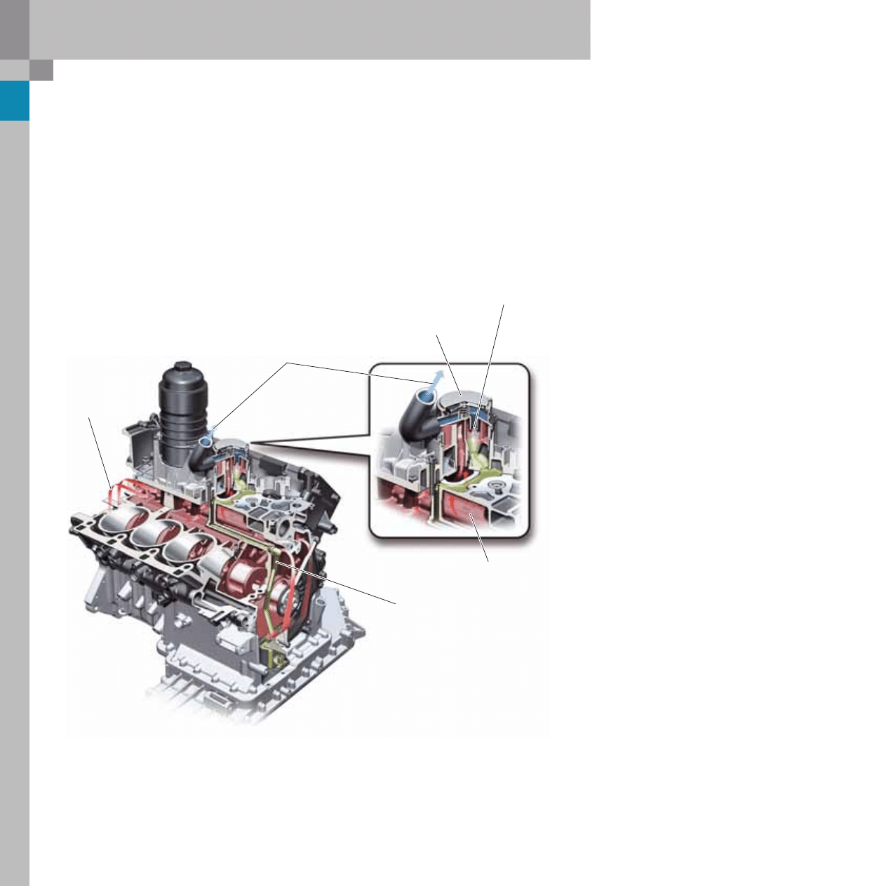
Crankcase breather system
An oil filter module in the inner vee of the engine
block accommodates the oil filter cartridge, the oil-
water heat exchanger and the oil separator of the
crankcase breather. The oil-water heat exchanger is
designed in such a way that the maximum oil tem-
perature remains well below the 150 °C max. limit
even in extreme conditions.
On the chain and belt sides of the engine, the
incoming blow-by gases flow through the settling
chamber in the inner vee to the three-cyclone oil
mist separator. The blow-by gases flow through the
settling chamber into the three-cyclone oil mist sep-
arator in which the existing fine oil particles are sep-
arated.
Almost all oil-free blow-by gases flow through the
pressure control valve to the intake side of both tur-
bochargers. The separated oil is channelled into an
oilway in the crankcase and an oil drain pipe with
integrated non-return valve below the oil level.
4.2 l V8 TDI engine with common rail injection system
Pressure control valve
for crankcase breather
Three-cyclone
oil mist separator
Settling chamber
15
365_027
Cooling system
The coolant pump and the thermostat are housed
in a shared pump housing outside the engine.
The water pump is driven the oil pump gear module
which is attached to the chain drive D via two stub
shafts.
The pump housing has two outputs to the pressure
side, each of which is routed to the outer side of the
crankcase. On both sides of the crankcase are
located press-fitted coolant distributor rails, each of
which has four inlets from where the coolant flows
into the water jackets between the cylinders.
The crankcase coolant chamber is split in two longi-
tudinally according to the cross-flow principle. As a
result, the coolant flows upwards from the crank-
case into the cylinder head, transversely through
the cylinder head and back to the crankcase on the
inside of the cylinder banks. A portion of the cool-
ant flows directly from the pressure side to the
intake side through small holes in the cylinder webs
in order to ensure rapid heat dissipation from the
cylinder.
The coolant which is channelled through the engine
collects in the inner vee of the crankcase, from
where it flows to the cooler or back into the engine
via the water pump depending on the thermostat
setting.
Coolant pump
Thermostat
Crankcase,
two-piece
to the
cooler
from
cooler
Return line from the engine
to the coolant pump
Inlet to engine
Coolant distributor rail
Right cylinder bank
Coolant distributor rail
Left cylinder bank
16
365_036
4.2 l V8 TDI engine with common rail injection system
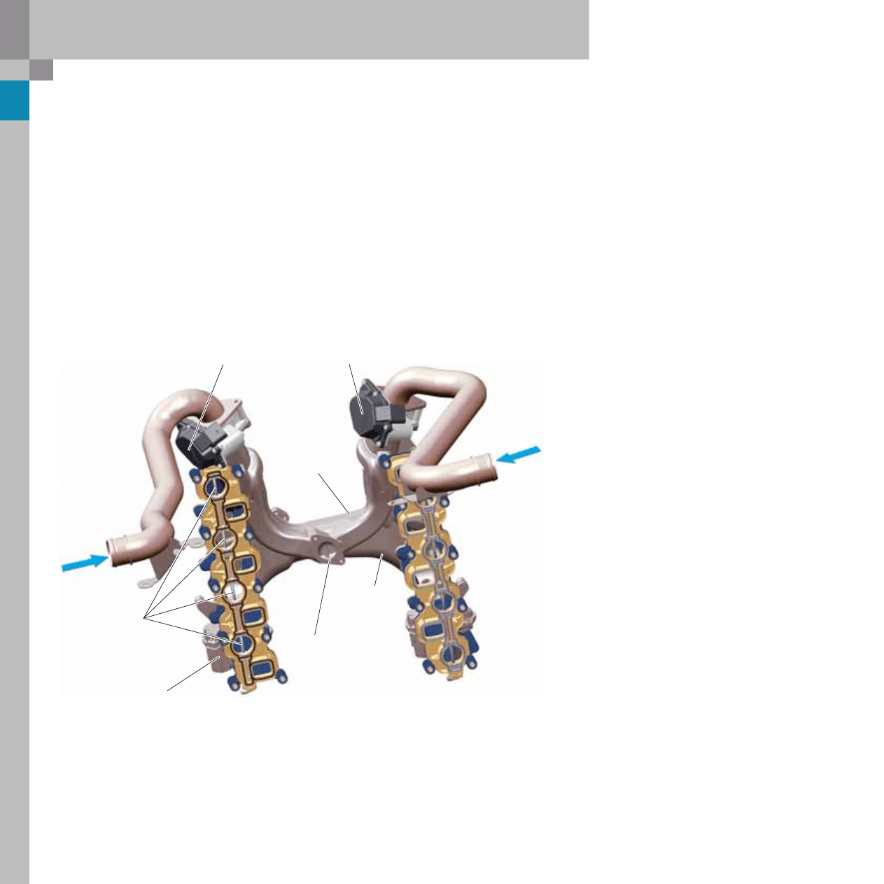
Air intake
The design of the double-chambered air intake sys-
tem, with two air filters, two air mass meters and
two air-air charge-air intercoolers, was adopted
from the 4.0 l V8 TDI engine.
Air is drawn in through the two electrically adjust-
able throttle valves. A connection between the two
cylinder banks in the charge air tube, the so-called
pressure equaliser tube, provides an even air distri-
bution and equalises the pressure between the cyl-
inder banks and the exhaust-gas return line.
Inflow of the recircu-
lated exhaust gases
from
turbocharger
from
turbocharger
Throttle valve positioner
Right cylinder bank
Throttle valve positioner
Left cylinder bank
Swirl flaps
Swirl flap adjuster
Connecting duct as
pressure equaliser tube
Charge air tube
The intake plenum, which is designed as a pressure
equaliser tube, is subjected to higher temperatures
due to the inflow of exhaust gases, and, therefore, is
made of aluminium. The actual intake manifold is
made of plastic and accommodates the intake man-
ifold flaps. These flaps control the flow rate in the
spiral duct and are used for adjusting the swirl
depending on thermodynamic requirements.
Each cylinder bank has a bidirectional electric
motor which actuates the flaps by means of a link-
age. Depending on operating state, there are open,
closed and intermediate positions.
17
365_041
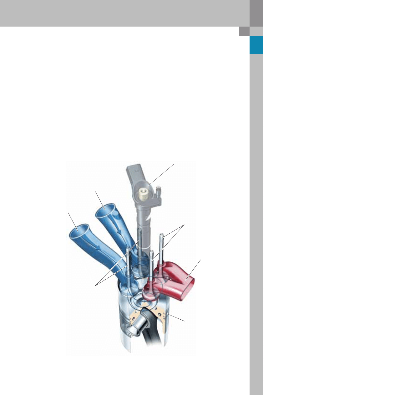
Combustion process
The main factors influencing the combustion pro-
cess in charged diesel engines are:
– Combustion chamber shape
– Compression ratio
– Injection hydraulics
– Swirl formation
– Turbocharging
They are in mutual interaction with one another. The
process was, therefore, optimised in iterative steps
by utilising, in particular, the flexibility provided by
the common rail system.
To achieve these ambitious development goals, the
combustion system with the new four-valve concept
used successfully in the 3.0 l V6 TDI engine was
taken as the basis and adapted for the eight cylin-
der.
The duct geometry in combination with variably
activated swirl flaps allows a broad propagation of
the cylinder swirl. The switchable EGR cooling sys-
tem significantly reduces untreated emissions,
since hot or cooled exhaust gas can be added
depending on the operating point and engine tem-
perature.
Four-valve concept
Piezoelectric injector
Exhaust valves
Exhaust port in the form
of a Y-branch pipe
Recessed-head type piston
Intake valves
Charging duct
Swirl duct
18
365_014
365_015
365_018
365_034
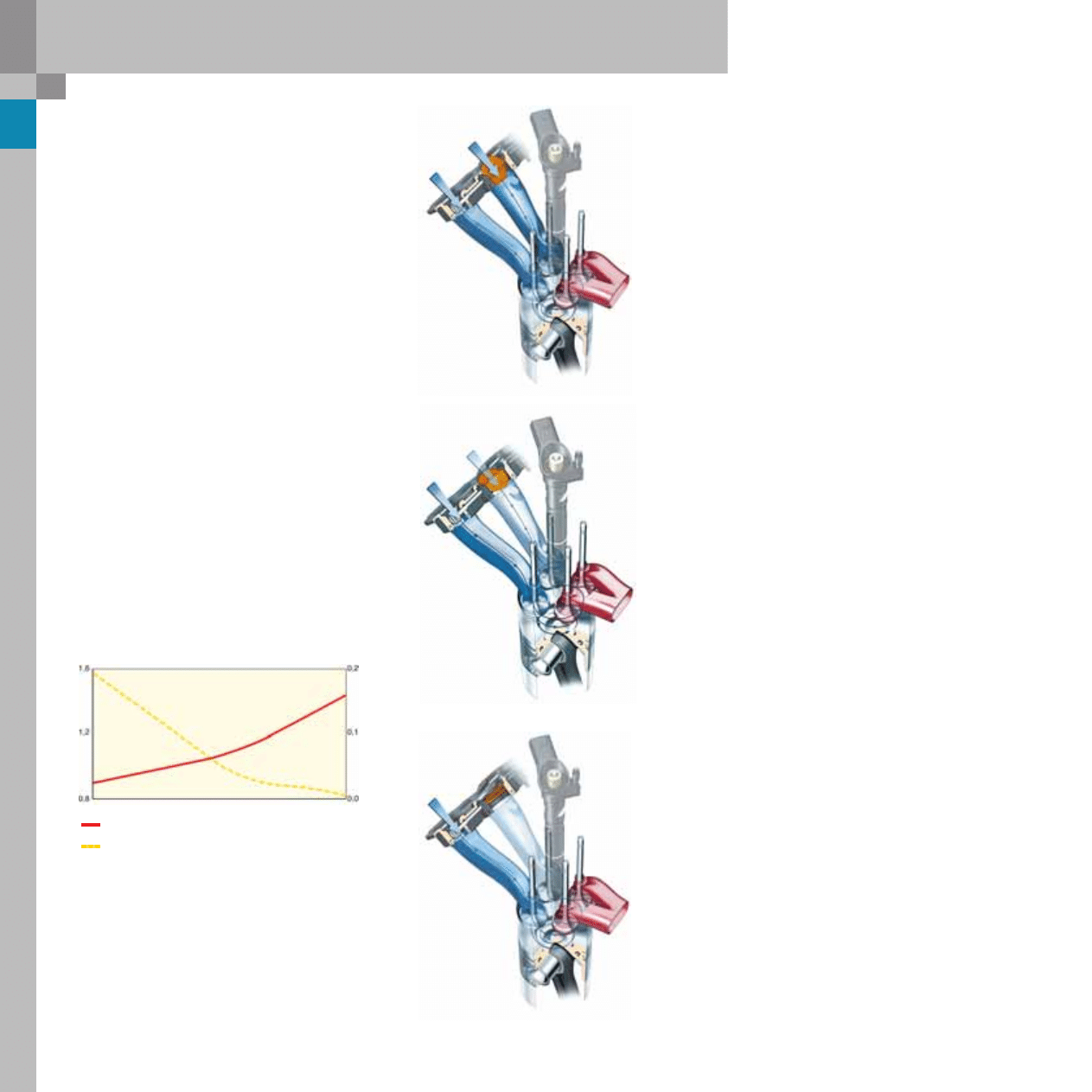
Swirl flap closed:
The strong swirl effect at low engine load optimises
the combustion process within the combustion
chamber and therefore results in fewer emissions.
Variable swirl flap:
To minimise untreated emissions, it is necessary to
precisely adapt the cylinder swirl and hence the
combustion process in dependence on the operat-
ing point. Requirement: continuous swirl flap
adjustment.
Swirl flaps
Swirl flap open:
The intake air can flow in large volumes through the
open intake ports and into the combustion cham-
ber, thereby ensuring optimal charging.
NO
x
Particulates
NO
x
emissions (g/kWh)
P
articulate emissions (g/kWh)
Swirl flap position
1200 rpm
4.2 l V8 TDI engine with common rail injection system
19
365_020
365_037
Exhaust gas recirculation
system
The exhaust gas flows from the exhaust manifolds
through ducts cast into the cylinder heads to the
EGR valves in the inner vee of the engine block. The
exhaust gas is precooled via the auxiliary exhaust-
gas recirculation duct by the cylinder head water
cooling system.
The EGR valves were modified for electrical - rather
than pneumatic - actuation, including position feed-
back, and protected against excessively high tem-
peratures by means of a water cooling system.
The precooled exhaust gases are subsequently
cooled by a pneumatically operated exhaust gas
recirculation cooler which enables cooling of the
exhaust gases to be adapted depending on the
operating point.
After passing through the exhaust gas recirculation
cooler, the exhaust gases flow up into a branching
duct within the pressure equalizer tube and mix
with the induced air flow directly downstream of the
throttle valves.
When designing the ducts and inlet points, special
attention was paid to optimal mixing of the dual gas
flows.
Exhaust-gas recirculation ducts
in the pressure equalizer tube
EGR valve,
right bank
EGR valve,
left bank
Exhaust gas recirculation
cooler with Bypass flap
Exhaust port from four-cylinder exhaust manifold
through the cylinder head to the EGR valve
Transverse duct in
the cylinder head
20
365_006
4.2 l V8 TDI engine with common rail injection system
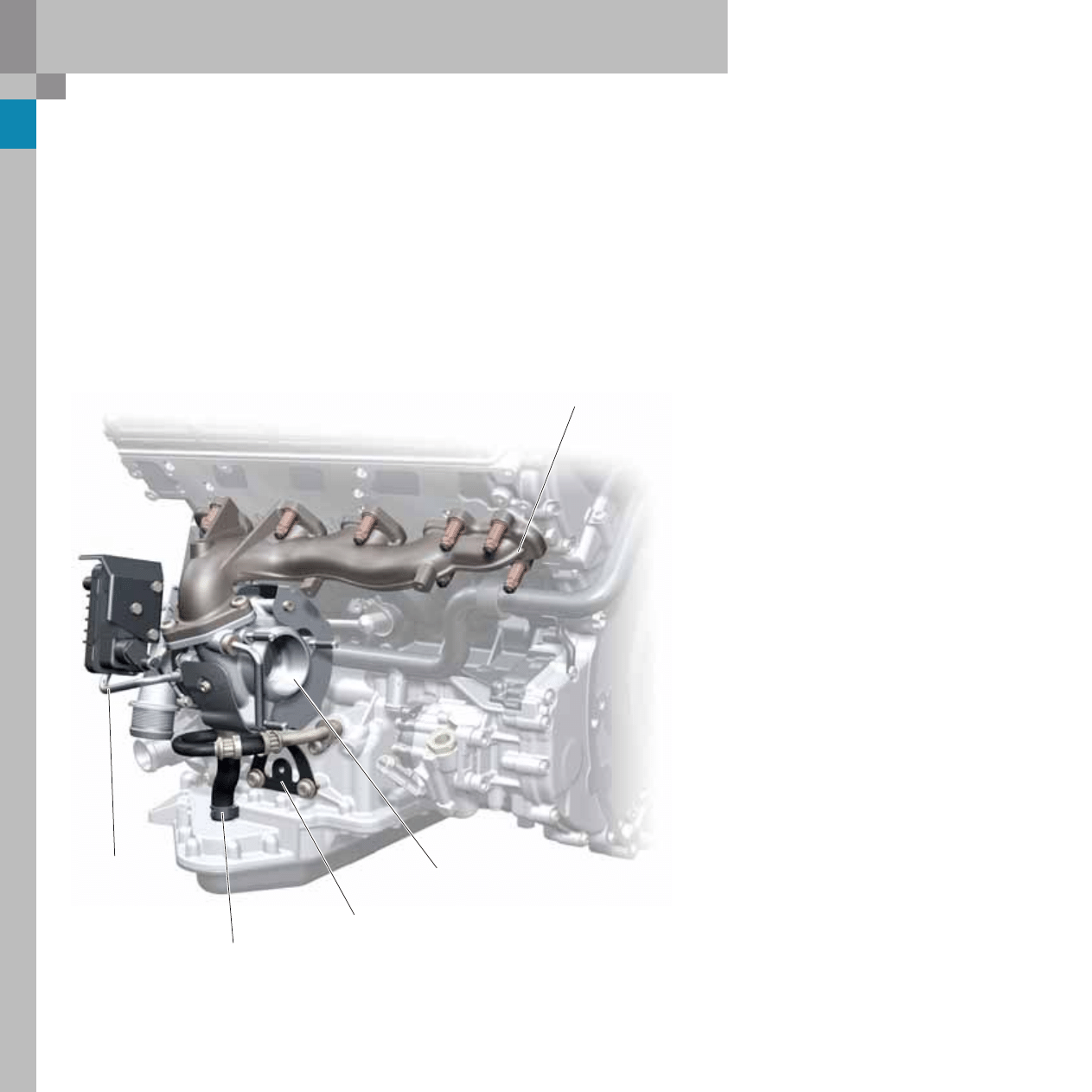
Exhaust manifold
The short gas paths between the cylinder head and
the turbocharger made it possible to change over
from an air-gap insulated exhaust manifold to a
pure cast manifold. This did not result in any addi-
tional heat loss for the oxidising catalytic converter.
Due to the higher rigidity of the cast manifold
(reduced oscillation), the design of the turbocharger
support has been simplified, thus influencing posi-
tively the natural oscillation of the components.
Exhaust gas tap for
exhaust gas recirculation
Support
Turbocharger
Coolant feed
for turbocharger
Oil return pipe, turbocharger
21
365_019
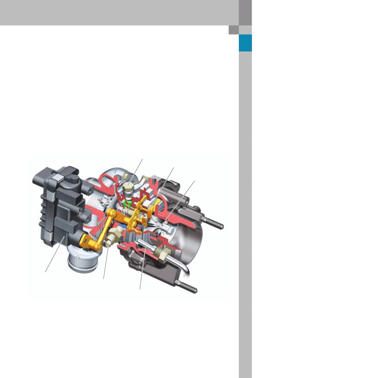
Turbocharger
Two Garrett GT17 chargers of the latest generation
with electrical actuators are used for charging.
The compressor wheel and the guide vanes were
optimised and the turbine-side fan was decoupled
from the turbine in order to increase turbocharger
speed (up to 226,000 rpm), exhaust gas temperature
(approx. 860 °C) and charge pressure (approx.
2.5 bar absolute) in order to enhance engine perfor-
mance.
Oil inlet
Charge pressure
control motor
The turbine side is now sealed by a double ring seal
instead of a single ring seal. This ensures a good
level of gas tightness, even at temporarily elevated
exhaust back pressures due to loaded particulate fil-
ters.
The engine management system has dual air mass
meters which ensure that both chargers run at the
same speed, and therefore have the same delivery
rate.
Decoupling of the fan and
double ring seal
Exhaust-gas temperature sensor
Coolant inlet
Air guide vanes
22
4.2 l V8 TDI engine with common rail injection system
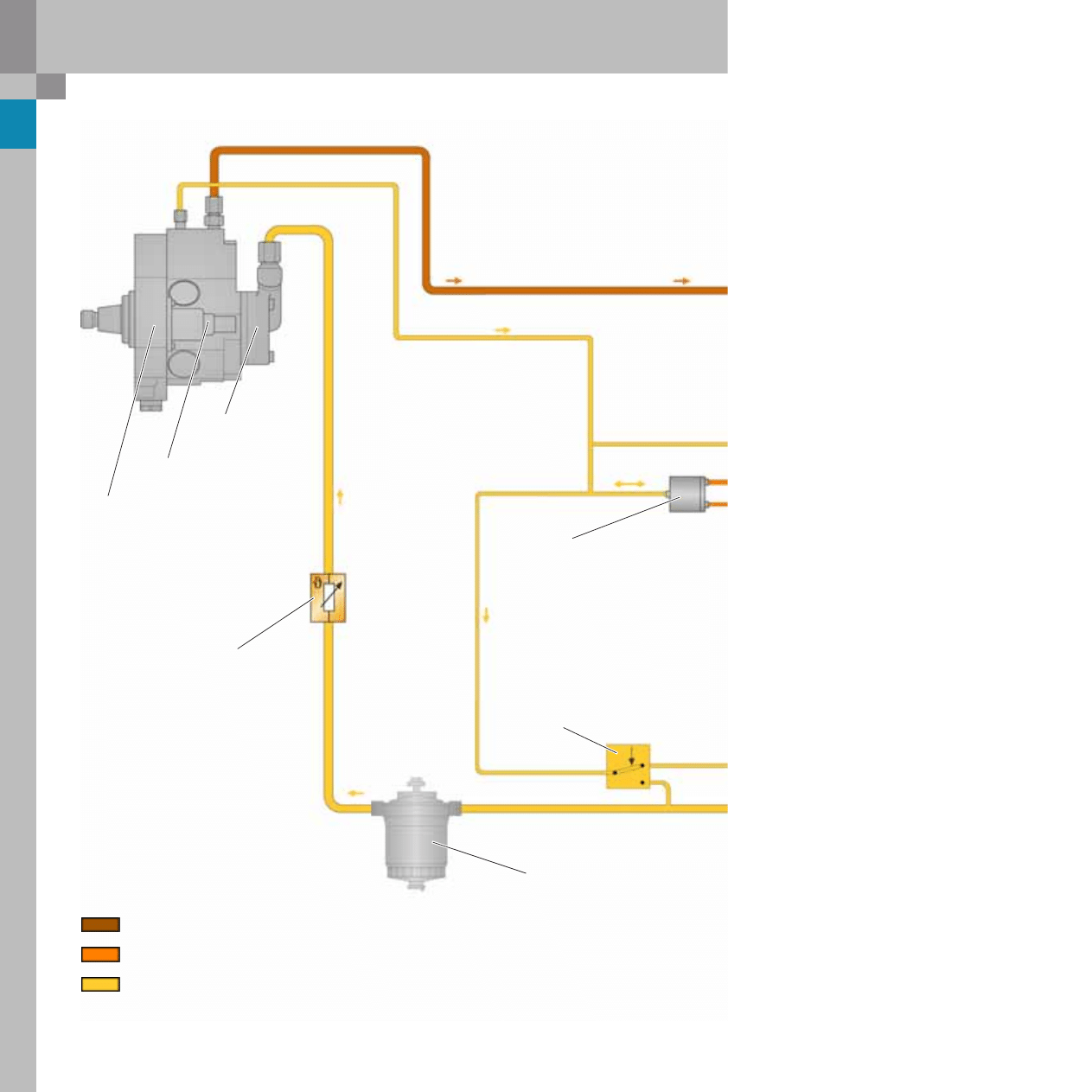
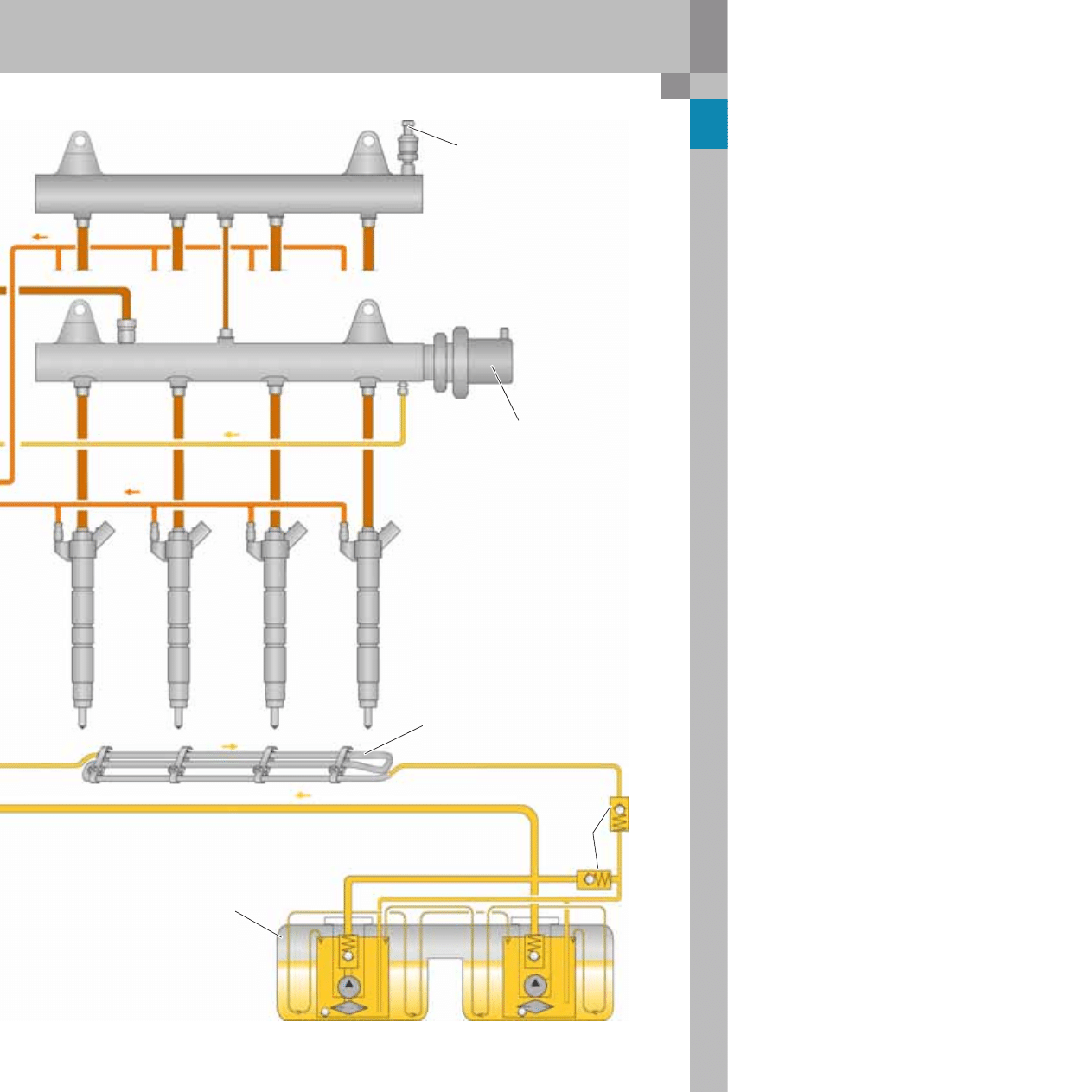
Fuel system
Fuel filter with
water separator
High-pressure pump
CP3.3
Fuel temperature sender
G81
Temperature-dependent
switchover
10 bar pressure retention valve
Permeability in opposite direction
at 0.3-0.5 bar for charging
the injectors after repair work.
Fuel metering valve N290
(fuel metering unit fuel metering unit)
Mechanical
fuel pump
4.5-6.2 bar
from 0.8-1.8 bar
200-1600 bar
max. permissible
pressure 1.8 bar
High-pressure 200-1600 bar
Return pressure from injector 10 -11 bar
Supply pressure max. 1.8 bar
Return pressure max. 1.8 bar
23
365_021
1
2
3
5
6
7
4
8
Rail element, cylinder bank II
Rail element, cylinder bank I
10-11 bar
Fuel pressure sender
G247
Fuel pressure control valve
N276
Fuel cooler (air)
on vehicle underbody
Injectors 1-4
N30, N31, N32, N33
Check
valve
Tank
Fuel tank module with suction
jet pump, non-return valve
and prefilter fuel pump
(pre-supply pump)
G23
G6
to injectors 5-8
N83, N84. N85, N86
24
365_032
Reference
For further information on design
and function, please refer to SSP 325 -
Audi A6 ´05 Engines and Transmissions.
4.2 l V8 TDI engine with common rail injection system
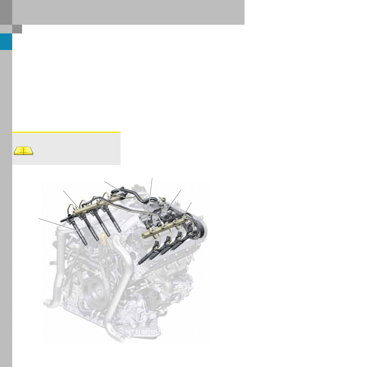
High-pressure fuel circuit
The three-piston high-pressure pump is located in
the inner vee of the engine, and is driven by the
intake camshaft of cylinder bank II via a toothed
belt.
The high-pressure circuit consists of the following
components:
– High-pressure pump with fuel metering valve
(fuel metering unit) N290.
– Rail element I with fuel pressure regulating valve
N276 and
– Rail element II with rail pressure sensor G247 and
8-port piezoelectric injectors.
Rail II
Fuel pressure regulating valve N276
Rail I
Fuel metering valve N290
Injector
Fuel pressure sender G247
It was possible to dispense with the distributor
block in the CR system, as used in the 4.0 l V8 TDI
engine.
This fuel pressure regulator and the fuel pressure
sensor were distributed along both rails.
The rails themselves are now of welded construc-
tion, and no longer of forged construction. The rails
are based on a seamlessly extruded steel tube, the
open ends of which are sealed with threaded plugs.
The connecting fittings for the high-pressure line
and the rail pressure sensor were attached by
capacitor discharge welding*.
*Notes
on capacitor discharge welding:
The advantage of this method lies in the very lim-
ited heat affected zone around the weld seam. Thus,
the basic structure of the raw material remains
unaltered.
25
Note
Make sure that the injector fuel line and
the connecting line
between the rails is tightened to the cor-
rect torque.
Deformed or damaged high-pressure lines
must not be reused, and must be replaced.
365_040
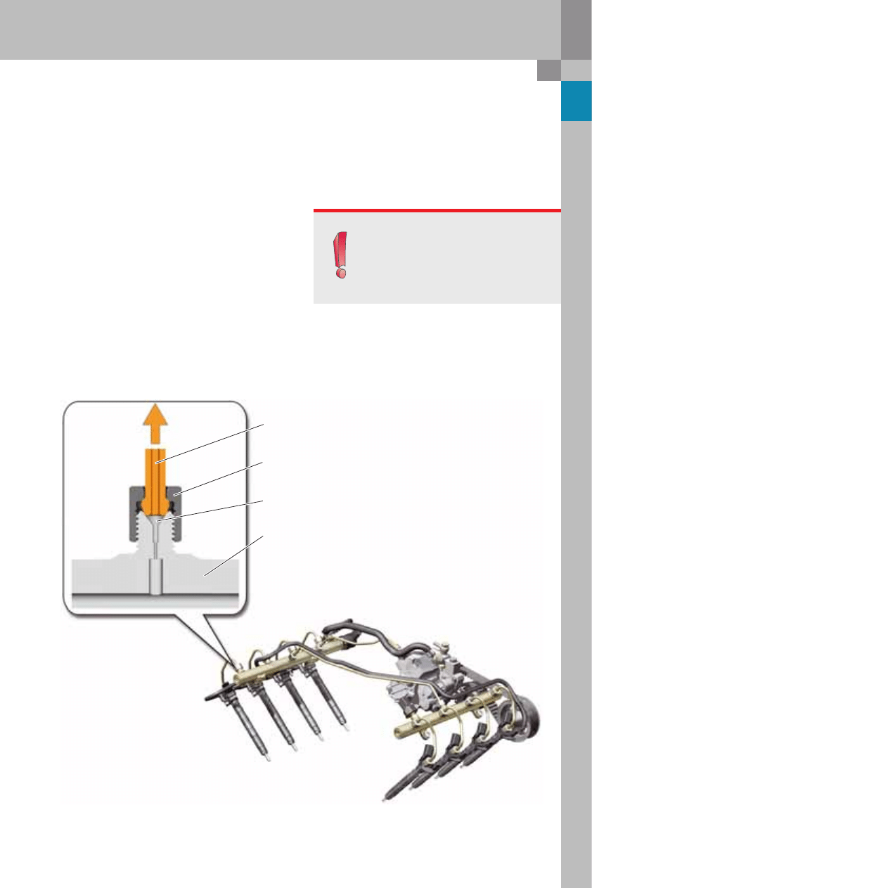
Restrictors in the rail
When the injector closes and during subsequent
injection cycles, a pressure wave forms at the injec-
tor outlet. This pressure wave propagates to the rail,
wher it is reflected.
To dampen the pressure waves, flow restrictors are
integrated in the rail in the supply line, in the high-
pressure pump rail, in the left and right rails and
upstream of each injector. These restrictors are pro-
duced by machining the outer surface of the rail.
Restrictor
Rail
Cap nut
High-pressure line
26
365_029
Note
In the event of a faulty fuel pressure regulat-
ing valve, the complete rail must be replaced.
365_028
365_033
Reference
For further information on design
and function, please refer to SSP 227 -
3.3 l V8 TDI Common Rail Injection System.
4.2 l V8 TDI engine with common rail injection system
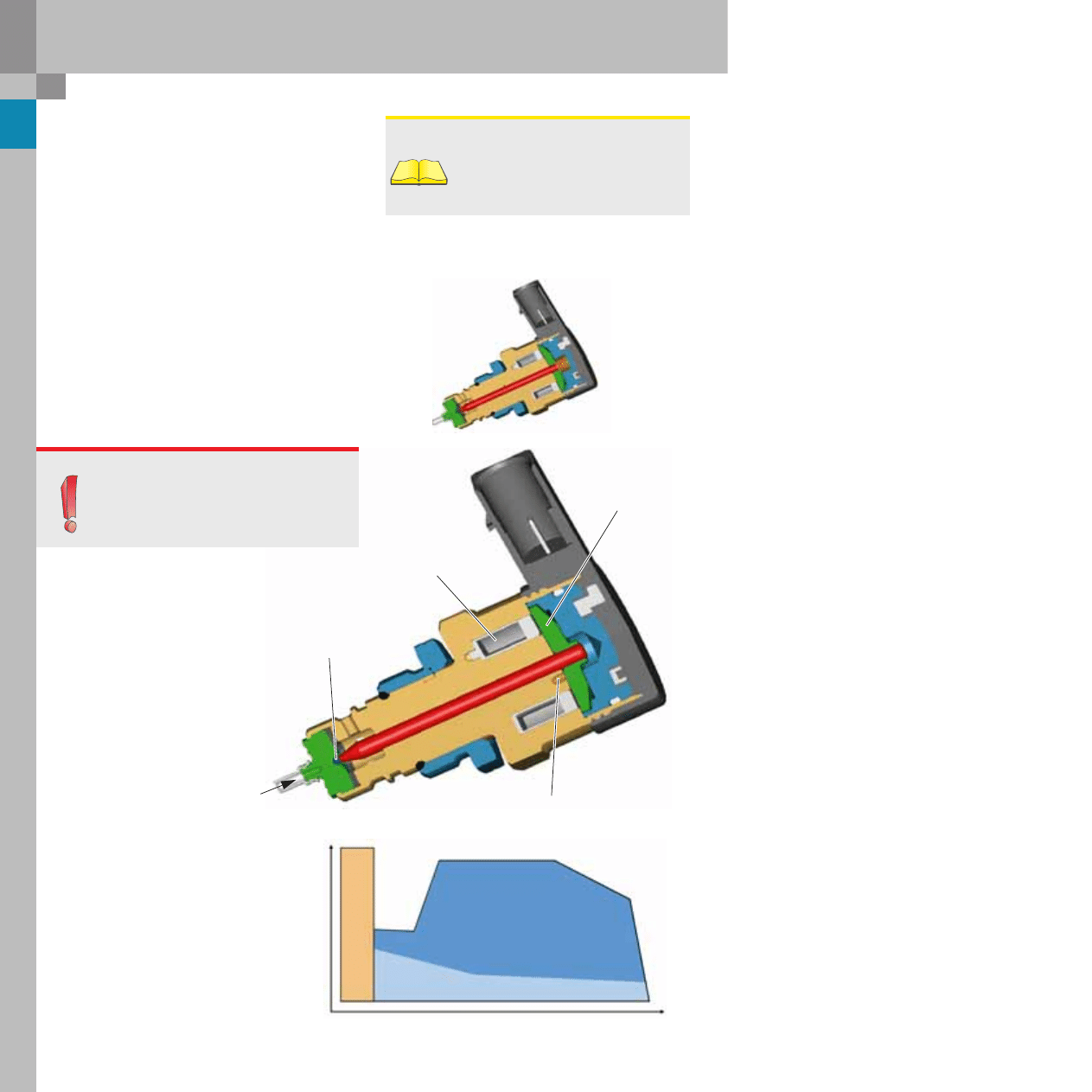
Fuel pressure regulating valve N276
A new fuel pressure regulating valve is used for the
common rail system of the 4.2 l V8 TDI engine. When
the valve is in a deenergised state, it ensures a
"short circuit“ between the high-pressure end and
the low-pressure end.
Function:
When the engine is running, the poppet valve is in
force equilibrium with the spring and the magnetic
circuit. The valve is open in the deenergised state
whereby the spring relieves the load on the ball in
the seat.
Unlike the previous version (which had a short-time
retention pressure of approx. 100 bar), the pressure
in the rail is reduced immediately, thus preventing
the fuel from draining into the cylinder if an injector
is open.
Iron plate
Valve seat ball
Applied
rail pressure
Compression spring
Previous version
Dual-regulator concept
The 3.0 l V6 TDI engine with common rail
used a dual-regulator concept which
activated the fuel pressure regulating
valve N276 or the fuel metering valve
(fuel metering unit) N290.
With this concept, the pressure can be
controlled simultaneously via the fuel
pressure regulating valve and the fuel
metering unit.
Speed
Injection r
ate
Fuel metering unit control at high
injection rates and high rail pressures
Dual-regulator operation at idle, when coasting
and at low injection rates
P
ressur
e r
egulating v
alve contr
ol
at engine start and f
o
r fuel he
atin
Armature
27
365_039
Note
When an injector is replaced,
the adaptation value for the new injector
must be written to the engine control unit.
When the engine control unit is replaced,
the injector rate matching values and the
injector voltage matching valve must be
transferred to the new engine control unit.
Reference
For further information, please refer to
SSP 325 - Audi A6 ´05 Engines and Trans-
missions.
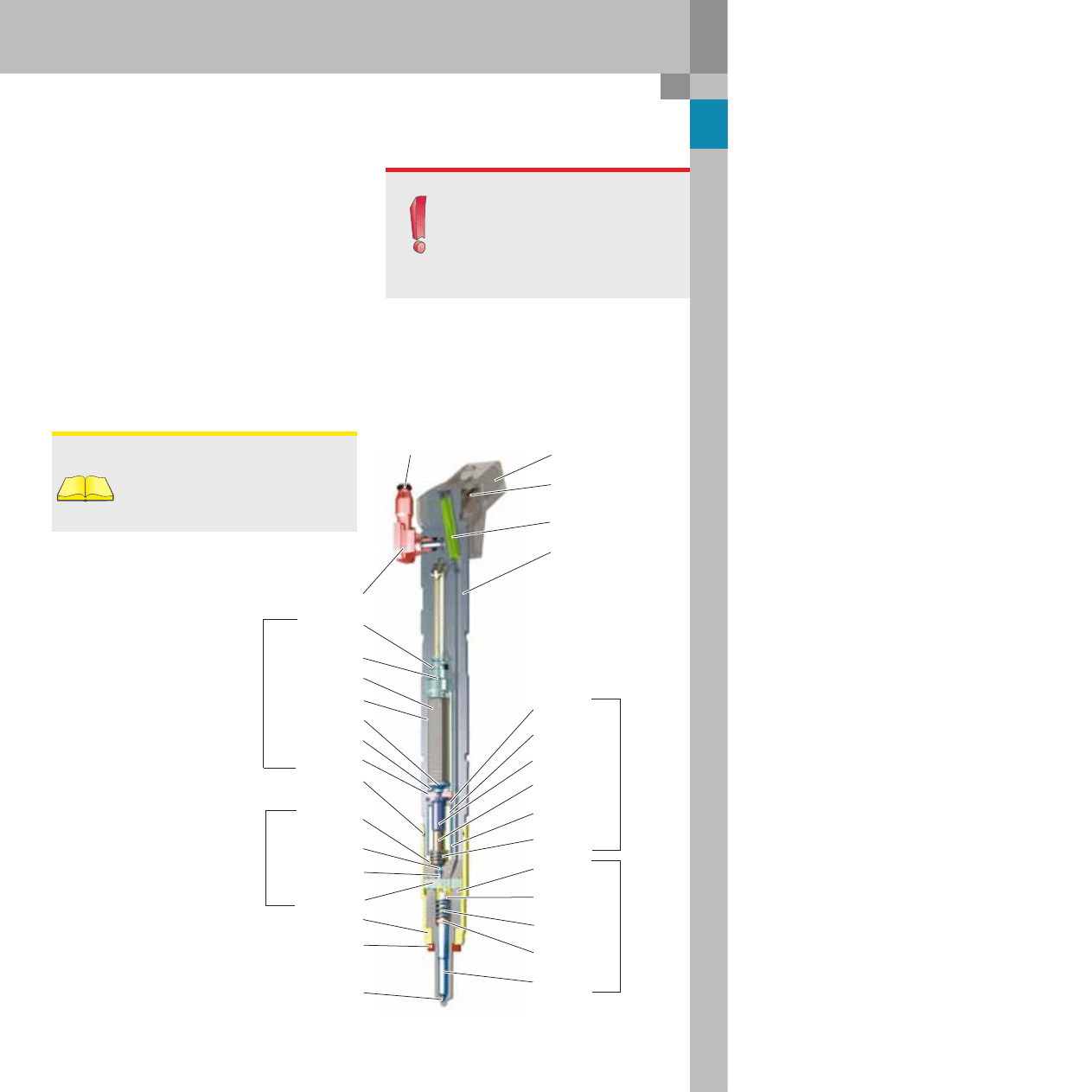
Piezoelectric injectors
By using piezoelectric injectors, it is possible to
achieve:
– multiple electrical activation periods per working
cycle,
– very short switching times for up to five injection
cycles,
– large forces counter to the current rail pressure,
– high stroke precision for rapid rail pressure
reduction
Depending on the rail pressure, piezoelectric injec-
tors require a drive voltage of between 110 and
148 V through capacitors in the control unit.
0-ring
Return connection
0-ring
Actuator foot
Actuator
Actuator sleeve
Actuator head
Adjusting piece
Electrical connection
(blade terminal)
Sealing disc
Rod filter
Actuator
module
Valve plate
Valve pin
Valve spring
Restrictor plate
Switch
valve
Adjusting disc
Injector spring
Spring retainer
Nozzle body
Injector pintle
Nozzle
module
Valve piston
Coupler piston
Coupler body
Adjusting disc
Valve piston spring
Coupler
module
Tubular spring
Low-pressure ring seal
Nozzle clamping nut
Membrane
Connector overmoulding
Body
Nozzle ports modified
from 7 to 8-port
28
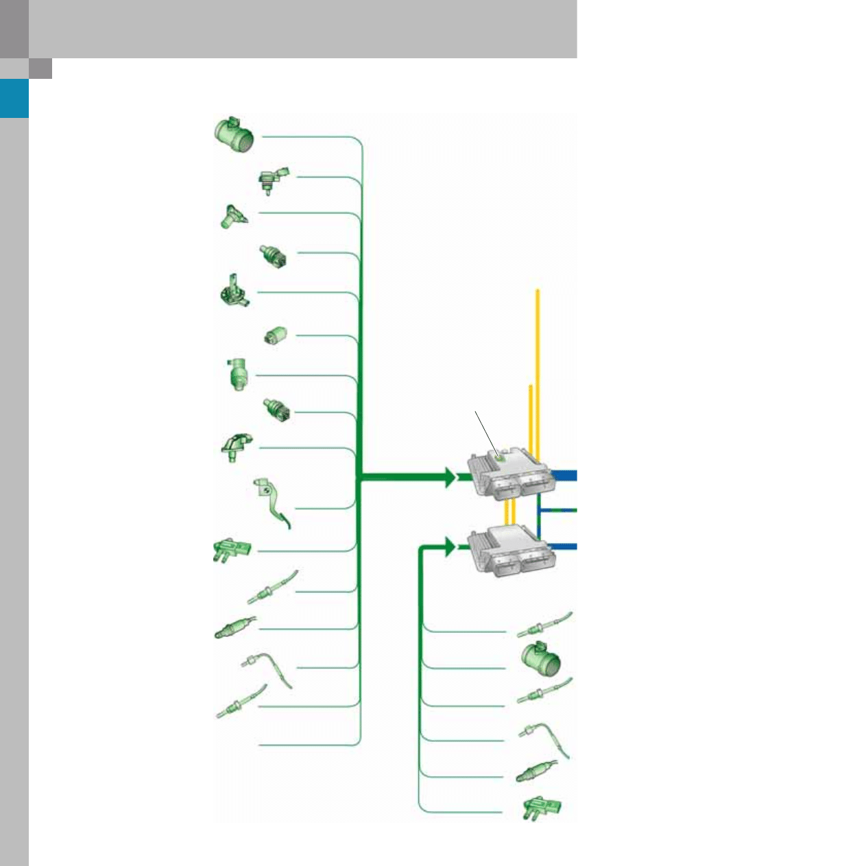
4.2 l V8 TDI engine with common rail injection system
System overview
Fuel temperature sender G81
Air mass meter G70
Engine speed sender G28
Hall sender G40
Exhaust gas pressure sensor 1 G450
Accelerator pedal position sender G79
Accelerator pedal position sender -2- G185
Lambda probe 1 G39
Engine control unit J623
(master)
Sensors
Charge pressure sender G31
Intake air temperature sensor G42
Coolant temperature sender G62
Oil temperature sender G8
Fuel pressure sender G247
Coolant temperature sender
at radiator outlet G83
Catalytic converter temperature sensor I G20
Exhaust gas temperature sender -1- G235
Exhaust gas temperature sender 2 for bank 1
G448
Auxiliary signals:
P/N signal
Term. 50 at starter
Start relay, term. 50 stage 1/2
Request start
Cruise control system
Auxiliary water pump (relay to control)
Engine control unit 2 J624
(slave)
CAN-High
CAN-Low
Altitude sender
P
owertr
ain CAN data bus
29
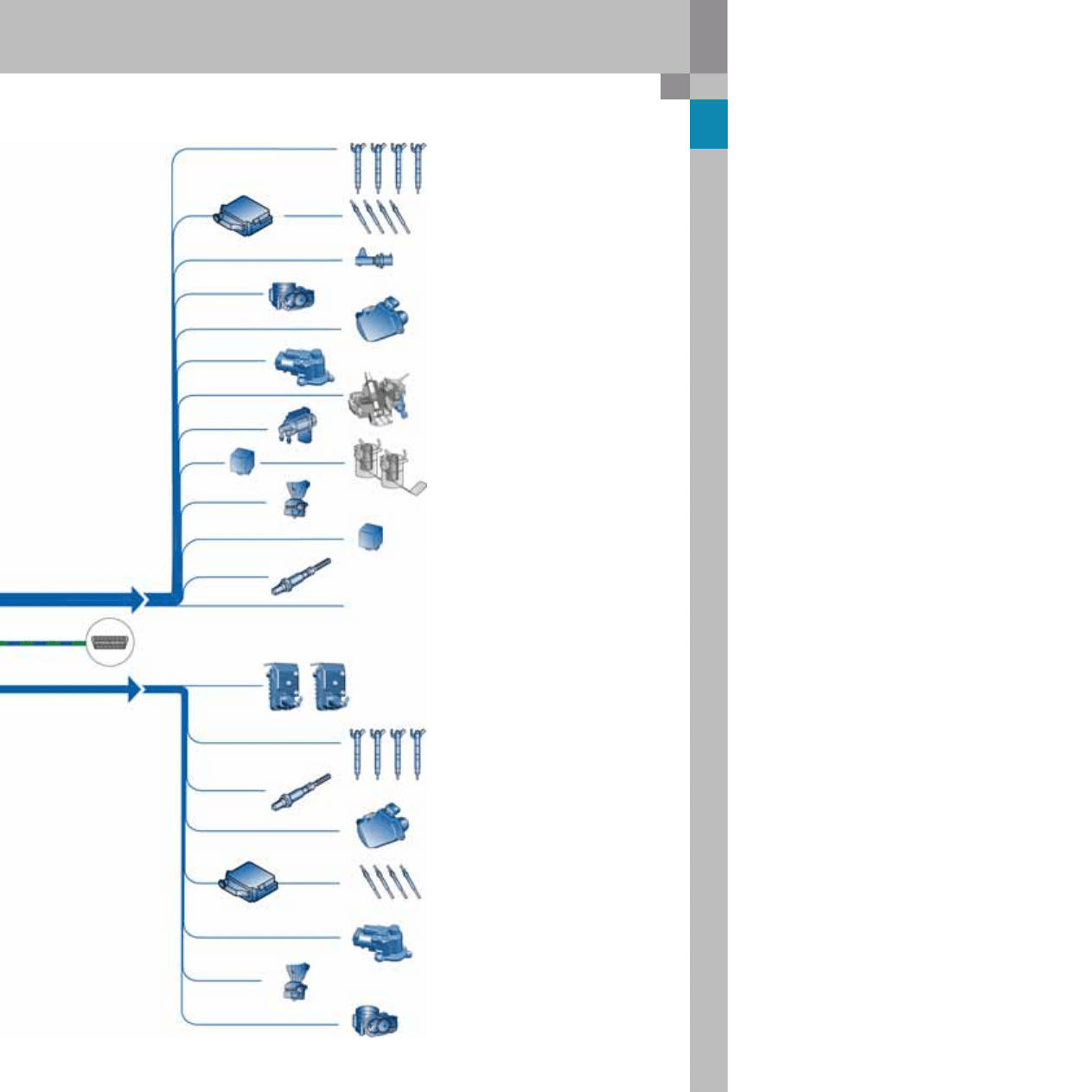
365_042
Intake manifold flap motor 2 V275
Throttle valve module J338
Fuel pressure regulating valve N276
Exhaust gas recirculation actuator V338
Fuel pump relay J17 and
fuel pump G6 and G23
Electro-hydraulic engine mounting solenoid valve,
right N145
Electro/hydraulic engine mounting solenoid valve,
left N144
Exhaust gas recirculation actuator 2 V339
Throttle valve module 2 J544
Actuators
Injectors for cylinders 1, 4, 6, 7
N30, N33, N84, N85
Fuel metering valve N290
Exhaust gas recirculation cooler change-over valve
N345
Engine component current supply relay J757
Auxiliary signals:
Radiator fan control unit PWM 1/2
Engine speed
Glow plugs for cylinders 2, 3, 5, 8
Q11, Q12, Q14. Q17
Glow plugs for cylinders 1, 4, 6, 7
Q10, Q13, Q15, Q16
Automatic glow period
control unit 1 J179
Diagnostic connection
Exhaust gas temperature sender 2
for bank 2
G449
Air mass meter 2
G246
Exhaust gas temperature sender -1-,
bank 2
G236
Catalytic converter
check temperature sensor II
G29
Lambda probe 2
G108
Exhaust gas pressure sensor 2 G451
Glow time control unit 2 J703
Intake manifold flap motor V157
Injectors for cylinders 2, 3, 5, 8
N31, N32, N83, N86
Lambda probe 2 heater Z28
Turbocharger 1 control unit J724
Turbocharger 2 control unit J725
Lambda probe heater Z19
30
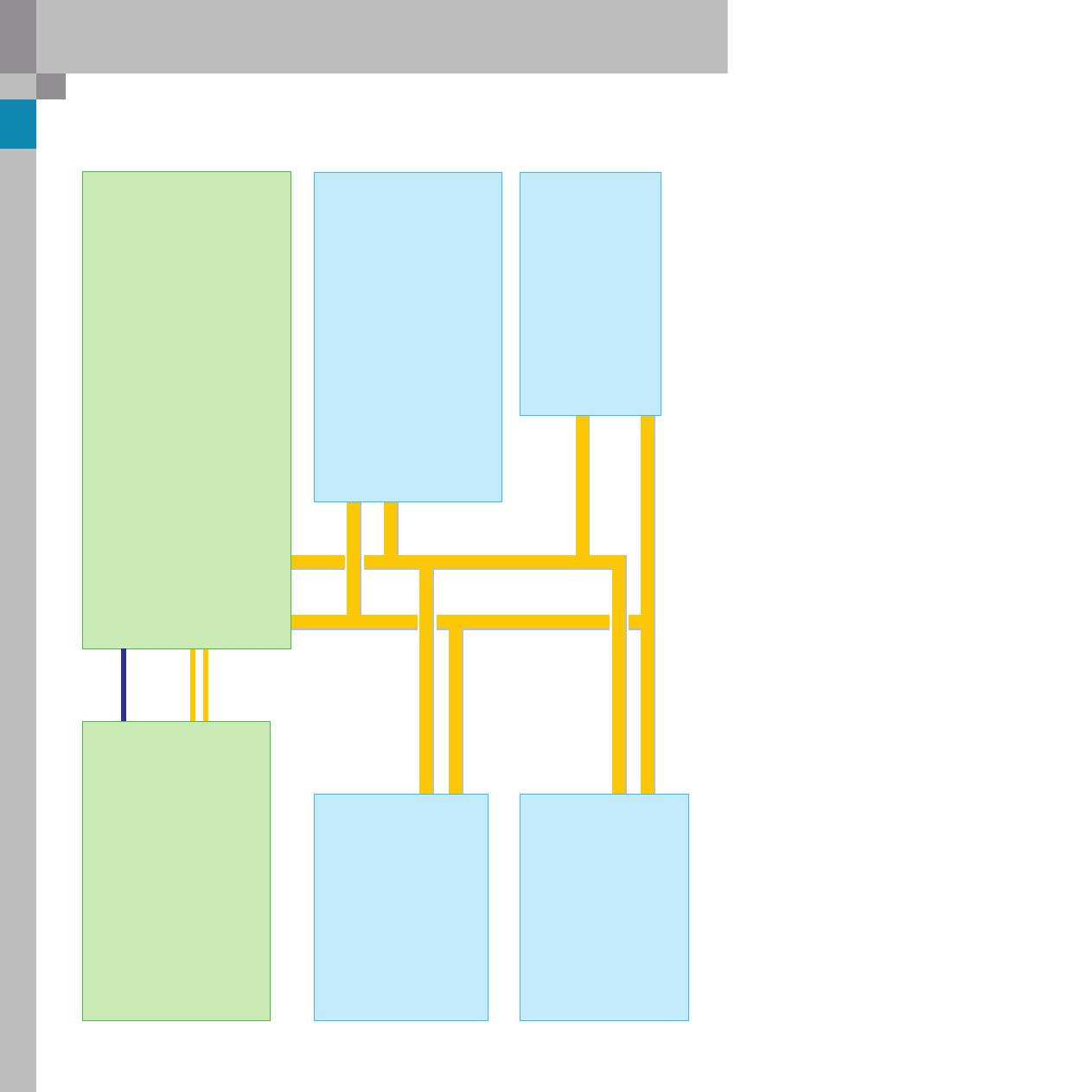
4.2 l V8 TDI engine with common rail injection system
Engine control unit (master) J623
Idling information (EBC)
Kick-down information
Clutch pedal switch
Engine speed
ACTUAL engine torque
Coolant temperature
Brake light switch information
Brake pedal switch
CCS switch positions
CCS nominal speed
NOMINAL/ACTUAL idling speed
Preglow signal
Throttle-valve angle
Intake temperature
OBD2 lamp
"Hot" coolant warning lamp
Fuel consumption
Radiator fan activation
Air conditioner compressor
Power reduction
Particulate filter lamp
Start module
Interlock switch
Starter enable
Starter de-mesh
Load shedding
Oil temperature
CAN High
CAN Low
CAN 2
Low
CAN 2
High
Discrete
line
Data bus diagnostic
interface J533
(gateway)
ACC information
Idle up
Mileage
Date
Time
Brake light
Trailer detector
Engine control unit 2 (slave)
J624
sends all information such as
the master control unit via
CAN 2 directly to the master
control unit.
The slave control unit also con-
trols:
- charge pressure for both
turbochargers
The signal from engine speed
sender G28 is also transmitted
via a discrete line.
CAN data bus interfaces
(powertrain CAN data bus)
Steering angle sensor G85
Steering wheel angle (is uti-
lised for pre-control of idling
speed and for calculating the
engine torque based on the
power demand of the power
steering system)
ABS control unit J104
TCS request
ABS request
EDL request
ESP intervention
ESP brake light switch
Road speed signal
EBC intervention torque
Lateral acceleration
Wheel speed
Automatic gearbox control unit
J217
Selector mechanism activated/
deactivated
Air conditioner compressor OFF
Torque converter lock-up clutch
state
Target gear
Selector lever position
NOMINAL engine torque
Motion resistance index (on
downhill gradients)
Limp-home program (information
on self-diagnosis)
OBD2 status
Turbine speed
Nominal idling speed
31
365_009
Reference
For further information on filter regenera-
tion, please refer to SSP 325 - Audi A6 ´05
Engines and transmissions.
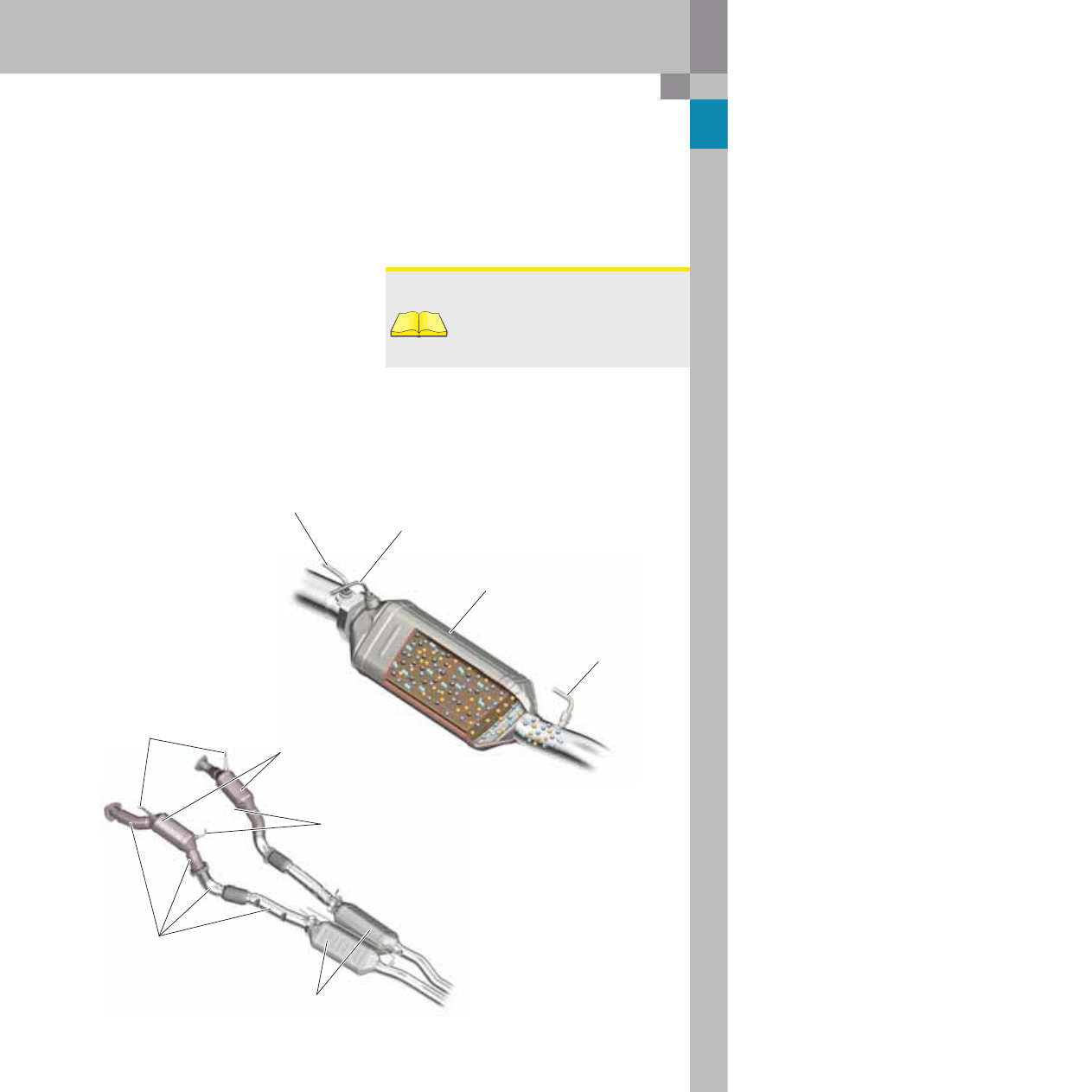
Exhaust system with diesel
particulate filter
A double-chambered exhaust system with particu-
late filter is used in combination the 4.2 l V8 TDI
engine. Each channel of the exhaust system com-
prises a close-coupled oxidising catalytic converter
and a catalysed soot diesel particulate filter located
in the under-body area. To minimise heat loss, the
pipes from the turbochargers to the diesel particu-
late filters are air-gap insulated.
As in the 3.0 l V6 TDI engine, a diesel particulate fil-
ter consisting of a thin-wall silicon carbite substrate
is used. Wall thickness has been reduced by 37 % to
increase cellularity and thus enlarge the active sur-
face area between the catalytic coating and the par-
ticulate layer. This helps to reduce the exhaust back-
pressure and ensure faster filter regeneration times.
The combination of a thin-wall substrate and a cata-
lytic coating allows controlled filter regeneration at
temperatures between 580 and 600 °C in addition to
low exhaust back-pressures.
Pressure line tap
upstream of diesel particulate filter
Temperature sensor
upstream of diesel particulate filter
Catalysed soot
diesel particulate filter
Pressure line tap
downstream of
diesel particulate filter
Temperature sensors downstream
of oxidising catalytic converter
Oxidising catalytic
converters
Lambda probes upstream of
oxidising catalytic converter
Air-gap insulated pipes
Diesel particulate filter
32
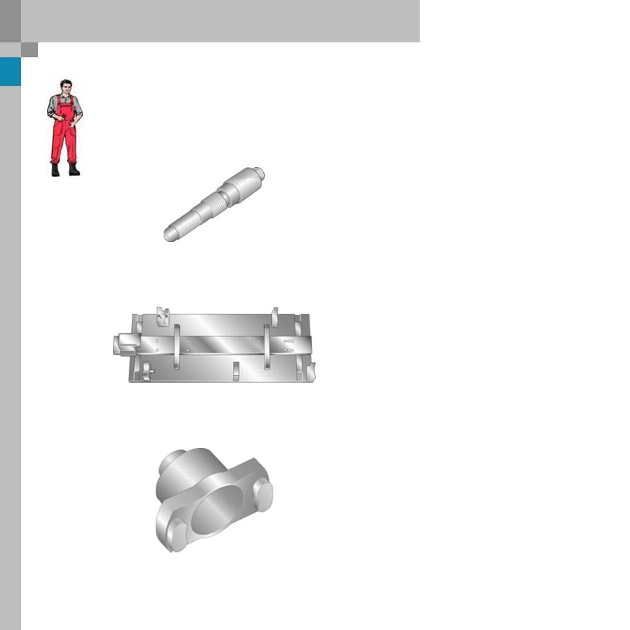
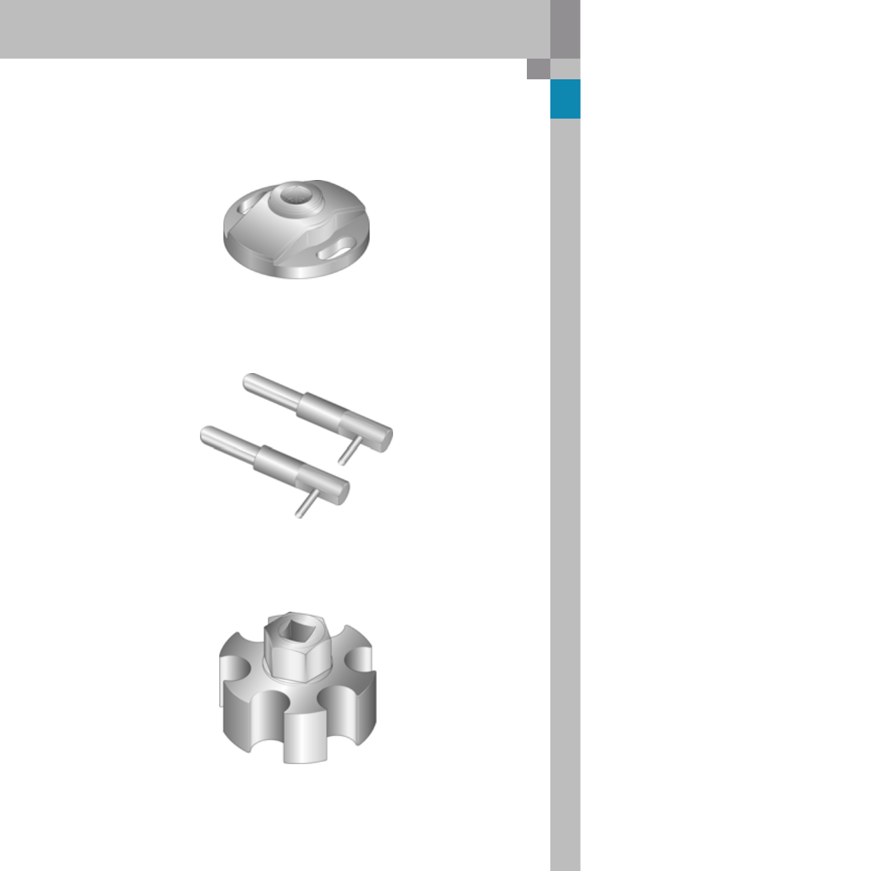
Special tools
365_049
365_048
365_050
4.2 l V8 TDI engine with common rail injection system
T40069
Locating pin
T40094
Camshaft insertion tool
T40062
Adaptor
Sprocket wheel
Here you can see the special tools
for the 4.2 l V8 TDI engine with common rail.
33
365_051
365_052
365_053
T40061
Adaptor
Camshaft
T40060
Timing pins
T40049
Adaptor

34
Notes
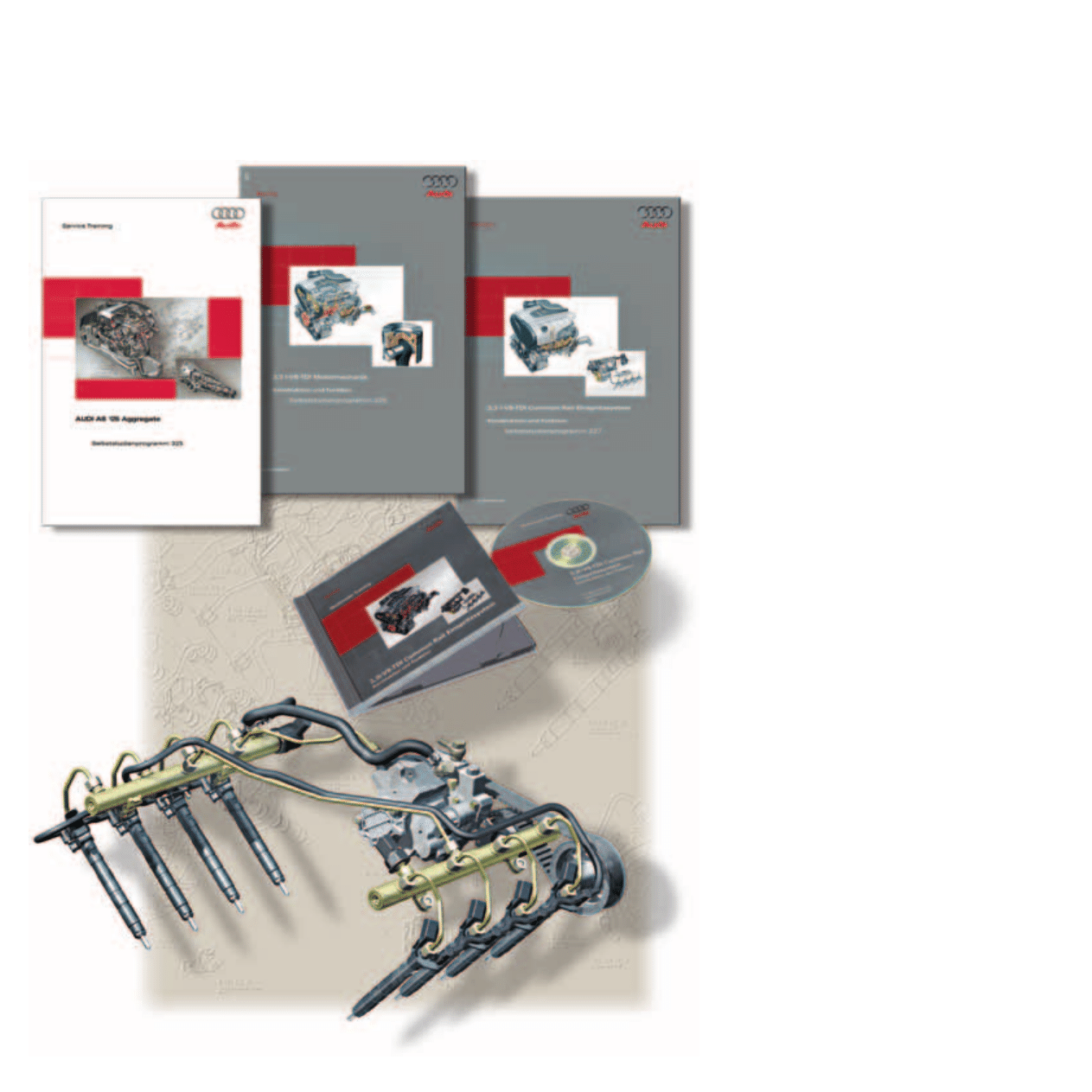
To broaden your knowledge of the common rail injection system,
the following self-study programmes and CBTs have been prepared:
365
All rights reserved. Technical
specifications subject to
change without notice.
Copyright
AUDI AG
N/VK-35
Service.training@audi.de
Fax +49-7312/31-88488
AUDI AG
D-74172 Neckarsulm
Technical status: 10/05
Printed in Germany
A05.5S00.18.20
Audi 4.2 l V8 TDI with
Common Rail Injection System
Self-Study Programme 365
Vorsprung durch Technik
www.audi.co.uk
Service Training
Wyszukiwarka
Podobne podstrony:
Self Study Programme 388 4 2L V8 4V FSI engine
Self Study Programme 279 2 0L 110kw with petrol direct injection FSI
Self Study Programme 351 Common rail fuel injection system fitted in the 3 0l V6 TDI engine
Self Study Programme 431 Audi RS 6
Self Study Programme 17 Octavia convenience electronic system
Self Study Programme 189 2 3L petrol engine in the LT 97
Self Study Programme 376 5 2 litre V10 FSI engine
Self Study Programme 396 Lane change assist
Self Study Programme 276 Phaeton automatic proximity control
Self Study Programme 280 Phaeton auxiliary heater top c and top z
Self Study Programme 288 Audi A8 03 distributed functions
Self Study Programme 398 Audi lane assist
zestaw 24 collocations with common verbs kolokacje z powszechnymi czasownikami
Extreme Self Care Program
ASM based Modelling of Self Replicating Programs
common rail
Uklad zasialania common rail
Wysokiego ciśnienia paliwa Common Rail pompa wtryskowa, Pompy wtryskowe diesel
Common Rail
więcej podobnych podstron