
Development of Wind Power Control System for
Six-Phase Permanent-Magnet Synchronous Generators
*Sheng-Nian Yeh, Jonq-Chin Hwang, Ming-Chih Hsieh, Li-Hsiu Chen
Department of Electrical Engineering, National Taiwan University of Science and Technology
43, Section 4, Keelung Road, Taipei 106, Taiwan
phone: 886-2-27376668 fax: 886-2-27376699 Email: snyeh@mail.ntust.edu.tw
Abstract: This paper presents the development of wind power system with 6-phase permanent-magnet
synchronous generators. The proposed system can not only yield high power density of generator and
capacity of power converters, but also reduce the voltage ripple at the output of rectifiers. A 6-phase,
full-controlled ac-to-dc power converter is used to convert varying voltages from 6-phase
permanent-magnet synchronous generator to constant dc voltage. The mathematic model of the
6-phase switching-mode rectifier is derived. The current control method of dual 3-phase synchronous
rotating frame transformation is proposed to reduce the current harmonics and increase the power
factor on input side of generator, and thereby increase the efficiency of the power converter. In
addition, a buck/boost chopper is designed to charge and discharge the battery set. Fixed-voltage
control method is used to supply load power from battery when speed of wind turbine is low. It thus
can accomplish the management of energy balance control and enhance the stability of the whole
system. A low-cost, 16-bit digital signal processor (DSP, TMS320LF2407A) is used to serve as the
core control device to implement a 768 W prototype generation system. The experimental data show
that the efficiency of the ac-to-dc power converter reaches 90%. The current harmonics and the power
factor on output side of generator are 3.34% and 0.95, respectively. Finally, experiments are given to
justify the feasibility of the proposed system.
Key words: 6-phase, permanent-magnet synchronous generator, power converter
I.
Introduction
This paper presents a high-performance, low-cost
and small-scale 6-phase permanent-magnet
synchronous wind power generation system. In a
traditional three-phase permanent-magnet
synchronous generator system, limited by the
technology of power converters, the power
conversion is possible only if a certain level of wind
turbine speed have been achieved [1].
A 6-phase, 24-slot, 22-pole permanent-magnet
synchronous generator (PMSG) is designed in this
paper. The stator is composed of a double Y
connection and mid-point tap architecture with
concentration windings. A corresponding 6-phase,
full-bridge, full-controlled ac-to-dc power converter
is also presented in this paper. According to different
dc-link connections, the proposed power converter
can be operated at series- or shunt-connected mode.
When the wind speed is in a specified range, the
power converter is switched to the shunt-connected
mode for normal operation, while when the wind
speed is low, the power converter is series-connected
in order to maintain a stable voltage in the dc-link.
This paper is concerned with the analysis and
implementation of a 6-phase ac-to-dc power
converter for low-capacity 6-phase
permanent-magnet synchronous wind-driven
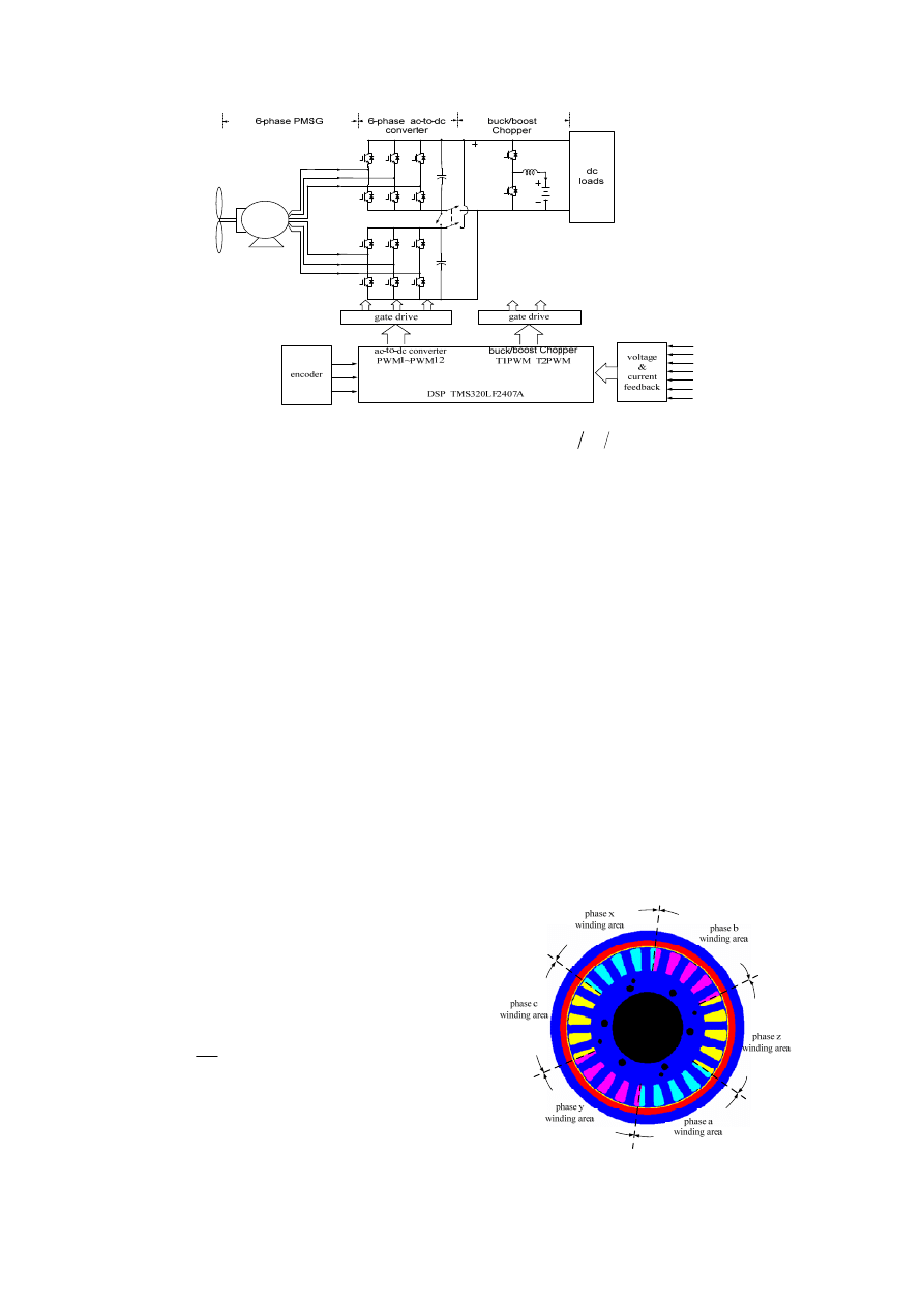
generator system. Fig. 1 shows the system topology.
It consists of a 6-phase wind-driven generator, an
encoder, a 6-phase full-bridge full-controlled power
converter, and a buck/boost dc chopper. All the
corresponding controllers are implemented and
integrated by a single digital signal processor (DSP).
II. Analysis and Implementation of the
6-phase PMSG system
The system consists of wind-driven generators,
battery sets, power converters, and digital controllers.
A servo-motor is used to drive the generator through
mechanical coupling for a simulation of wind-blade
subsystem. To cope with the ac-to-dc power
converter, an encoder at the rotor is introduced to
provide angle feedback of magnetic poles.
The rectifier converts 6-phase ac current from the
generator to a stable 48 V dc-link voltage. In order to
improve the reliability of the dc power, a 36 V
battery set is installed to work with buck/boost
choppers to maintain constant dc-link voltage and
power balance for varying wind speed [2].
The digital control unit is based on a low-cost
16-bit DSP manufactured by Texas Instrument. It has
40 million instructions per second (MIPS) execution
speed, which is quite suitable for the development of
this system. The interface circuits of the DSP consist
of four major parts. They are one joint test action
group (JTAG) port for debugging, two groups of
pulse-width modulation (PWM) circuits, 16 channels
of 10-bit analog-to-digital (A/D) converters for the
system voltage and current feedback, and a pulse
decoding circuit for the encoder. All are for the
current and power control of the 6-phase
permanent-magnet synchronous wind-driven
generator system.
1/7
PMSG
6
φ
a
T
−
b
T
−
c
T
−
a
T
+
b
T
+
c
T
+
x
T
−
y
T
−
z
T
−
x
T
+
y
T
+
z
T
+
2
dc
C
1
dc
C
b
L
B
T
+
B
T
−
B
v
B
i
dc
v
b
i
B
i
B
v
y
i
x
i
a
i
a
i
x
i
y
i
b
i
c
i
z
i
dc
v
A
B
Z
1
S
2
S
Fig. 1 Topology of a 6-phase wind-driven power generator system.
A. 6-phase PMSG
The permanent magnet of the generator uses
rare-earth material. It has several outstanding
properties including high residual induction, high
coercivity, high magnetic energy product, and linear
demagnetization curve [3]. These properties allow
larger air gap and magnetic flux density in machines,
and bring flexibilities to the installation of permanent
magnets and the design of magnetic circuits. It is
possible to produce generators that are different from
the traditional ones in their architectures, shapes,
sizes, according to the requirements of applications.
The material of NdFeb (N42) is applied for the
proposed 6-phase PMSG in this paper.
The winding of the 6-phase generator only has to
bear a current that is half of the current in a 3-phase
generator. This is because that the 6-phase generator
has two groups of 3-phase windings, and is thus
easier to remove waste heat. A commercial software
package called Magsoft Flux2D is used in this paper
to implement the analysis on magnetic circuits and
electric properties of the generator system required.
Fig. 2 shows the simulated section drawing of the
proposed generator.
The analysis is conducted by using the mathematic
model of the 6-phase PMSG, and calculating the
related parameters such as equivalent flux linkages,
stator equivalent resistors, and winding inductances
[4]. When the generator is under no-load, its output
phase voltage equals the magnetization voltage
.
Hence, the stator equivalent magnetic flux linkage
can be expressed as:
m
E
m
m
r
E
λ
ω
′ =
(1)
Since the generator is built by a double Y connection
and mid-point tap architecture, one can find its dc
resistance by applying a dc voltage between any two
phases [5]. The equivalent stator resistance can be
obtained as:
2
s
dc
dc
R
V
I
=
(2)
Transforming to synchronous frame [6], one can
obtain the quadrature- and direct-axis inductances
from the following equations by retrieving the output
voltages, the output currents, and the rotation speed:
'
1
1
11 1
12
r
r
r
r
r m
q
s q
r
d
d
r
d
d
v
r i
L
i
L
i
ω λ
ω
ω
=
+
+
+
2
)
1
r
1
)
(3)
1
1
11 1
12 2
0
(
r
r
r
r
d
s d
r
q
q
q
q
v
r i
L
i
L
i
ω
=
+
−
+
(4)
'
2
2
22 2
21
r
r
r
r m
q
s q
r
d
d
r
d
d
v
r i
L
i
L
i
ω λ
ω
ω
=
+
+
+
(5)
2
2
22 2
21
0
(
r
r
r
r
d
s d
r
q
q
q
q
v
r i
L
i
L
i
ω
=
+
−
+
(6)
Since the generator is of the surface mounted type,
the self-inductances of the windings in quadrature-
and direct-axis are the same. i.e.,
11
11
q
d
L
L
=
(7)
22
22
q
d
L
L
=
(8)
Due to the fact that the mutual inductances
12
q
L
,
12
d
L
,
21
q
L
, and
21
d
L
are small, they are neglected.
From equations (1) to (8), one obtains the magnetic
flux linkages of 0.039V-s/rad, the stator equivalent
resistance of 0.23 ohm, and the self-inductances
11
22
11
22
0.31
q
q
d
d
L
L
L
L
m
=
=
=
=
H
.
Fig. 2 Sectional drawing of the magnetic circuit
analysis for the proposed generator.
2/7
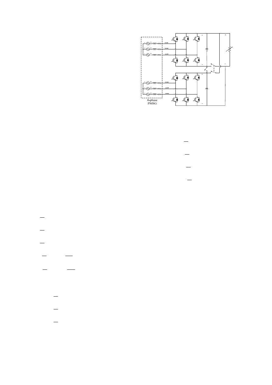
B. 6-phase ac-to-dc power converter
A 6-phase ac-to-dc full-bridge full-controlled
power converter is proposed as shown in Fig. 3,
where
is the dc-link voltage;
and
are the capacitances of the dc-link;
signifies
resistive load. Appropriate switching control in the
converter can yield unity power factor, small dc-link
voltage ripples, and reduce the harmonic loss of the
generator [7]. Continuous conduction mode is
exercised to have less generator output current
harmonics, and thereby results in sinusoidal current
waveform. In addition, to avoid shorting the rectifier,
the upper and lower power switches of the same arm
must be operated mutual exclusively with dead time.
dc
v
1
dc
C
2
dc
C
dc
R
Table 1 lists the operation modes of the proposed
converter. When the wind generator is running at low
speed, the converter is switched to series-mode to
maintain a stable dc-link voltage of the form
. On the other hand, when the wind
speed lies within a normal range, the converter is
switched to parallel-mode. Since the 6-phase ac-to-dc
power converter is composed of two groups of
three-phase ac-to-dc converters, the current passing
though the power transistors of the converters can be
distributed equally. Besides, if one group fails, the
system is capable of providing an output with half of
the rated power. It is more reliable than conventional
converters.
1
dc
dc
dc
v
v
v
=
+
2
From Fig. 3 and the parameters obtained above,
the differential equations from the winding a-b-c and
the dc-link capacitors can be expressed as:
11
a
a
s a
d
L
i
e
R i
v
dt
=
−
−
a
(9)
11
b
b
s b
d
L
i
e
R i
v
dt
= −
−
b
(10)
11
c
c
s c
d
L
i
e
R i
v
dt
= −
−
c
(11)
1
1
1
1
dc
dc
dc
a
a
b b
c c
dc
dc
v
d
C
v
i
i S
i S
i S
i
dt
R
= −
=
+
+
−
1
(12)
2
2
2
2
dc
dc
dc
x
x
y
y
z
z
dc
dc
v
d
C
v
i
i S
i S
i S
i
dt
R
= −
=
+
+
−
2
(13)
The corresponding equations for winding x-y-z are
similar to (9)-(11). i.e.,
22
x
x
s x
d
L
i
e
R i
v
dt
= −
−
x
(14)
22
y
y
s y
d
L
i
e
R i
v
dt
=
−
−
y
(15)
22
z
z
s z
d
L
i
e
R i
v
dt
= −
−
z
(16)
In the proposed system, the output voltages and
currents are time-varying, and its dynamic analysis
and control are relatively difficult. Therefore, the
dual three-phase synchronous rotating frame is used
a
T
−
b
T
−
c
T
−
x
T
−
y
T
−
z
T
−
a
i
b
i
c
i
x
i
y
i
z
i
s
R
s
R
s
R
s
R
s
R
s
R
22
L
22
L
22
L
x
e
y
e
z
e
1
dc
v
2
dc
v
1
dc
C
2
dc
C
dc
v
dc
R
a
T
+
b
T
+
c
T
+
x
T
+
y
T
+
z
T
+
a
e
b
e
c
e
11
L
11
L
11
L
1
S
2
S
Fig. 3 Topology of the 6-phase full-bridged,
full-controlled converter.
to simplify controller design [9]. For the balanced
6-phase generator output system, the quadrature- and
direct-axis voltage equations can be written as:
1
1
1
11
1
11
(
)
r
r
r
r
r
q
q
s q
q
q
r
q
d
d
v
e
R i
L
i
L
i
dt
ω
=
−
+
−
1
(17)
1
1
1
11
1
11
(
)
r
r
r
r
d
d
s d
d
d
r
d
d
v
e
R i
L
i
L
i
dt
ω
=
−
+
+
1
r
q
(18)
2
2
2
22
2
22
(
)
r
r
r
r
r
q
q
s q
q
q
r
q
d
d
v
e
R i
L
i
L
i
dt
ω
=
−
+
−
2
(19)
2
2
2
22
2
22
(
)
r
r
r
r
r
d
d
s d
d
d
r
d
q
d
v
e
R i
L
i
L
i
dt
ω
=
−
+
+
2
r
°
°
− °
°
°
−
°
°
°
°
°
m
(20)
Since the system is linear, proportional-integral
controllers are applied for generator output current
tracking. Suppose that the generator voltages are:
cos
a
r m
e
ω λ
θ
′
=
(21)
cos(
120 )
b
r m
r
e
ω λ
θ
′
=
−
(22)
cos(
240 )
c
r m
r
e
ω λ
θ
′
=
−
(23)
cos(
30 )
x
r m
r
e
ω λ
θ
′
=
(24)
cos(
150 )
y
r m
r
e
ω λ
θ
′
=
−
(25)
cos(
270 )
z
r m
r
e
ω λ
θ
′
=
−
(26)
With appropriate control parameters, the
corresponding generator output currents are:
1
cos(
)
a
m
r
i
i
I
θ θ
=
(27)
1
cos(
120 )
b
m
r
i
i
I
θ θ
=
− −
(28)
1
cos(
240 )
c
m
r
i
i
I
θ θ
=
− −
(29)
2
cos(
30 )
x
m
r
i
i
I
θ θ
=
− −
(30)
2
cos(
150 )
y
m
r
i
i
I
θ θ
=
− −
(31)
2
cos(
270 )
z
m
r
i
i
I
θ θ
=
− −
(32)
where
and
are peak output currents of
windings a-b-c and x-y-z, and
is the phase
difference between the output voltages and the output
currents. Transforming
1
m
I
2
m
I
i
θ
(21)-(26) into synchronous
frame yields the quadrature- and direct-axis voltages
of the generator:
1
r
q
r
e
ω λ′
=
(33)
3/7

1
0
r
d
e
= (34)
2
r
q
r
e
ω λ′
=
m
i
i
i
i
(35)
2
0
r
d
e
= (36)
Likewise, transforming (27)-(32) into synchronous
frame results in:
1
1
cos
r
q
m
i
I
θ
=
(37)
1
1
sin
r
d
m
i
I
θ
=
(38)
2
2
cos
r
q
m
i
I
θ
=
(39)
2
2
sin
r
d
m
i
I
θ
=
(40)
From (33)-(36) and (37)-(40), one can get the real
and reactive powers from the generator:
1
3
2
r
abc
r
m q
P
ω λ
′
=
i
(41)
1
3
2
r
abc
r
m d
Q
ω λ
′
=
i
(42)
2
3
2
r
xyz
r
m q
P
ω λ
′
=
i
(43)
2
3
2
r
xyz
r m d
Q
ω λ
′
=
i
(44)
From (37)-(44), one can let the direct-axis current be
zero, then the quadrature-axis currents will have the
same peak values of the generator output current,
when the output currents are in phase with output
voltages. Under this circumstance, the reactive power
of the generator output is zero, and the active power
can be controlled by the quadrature currents
and
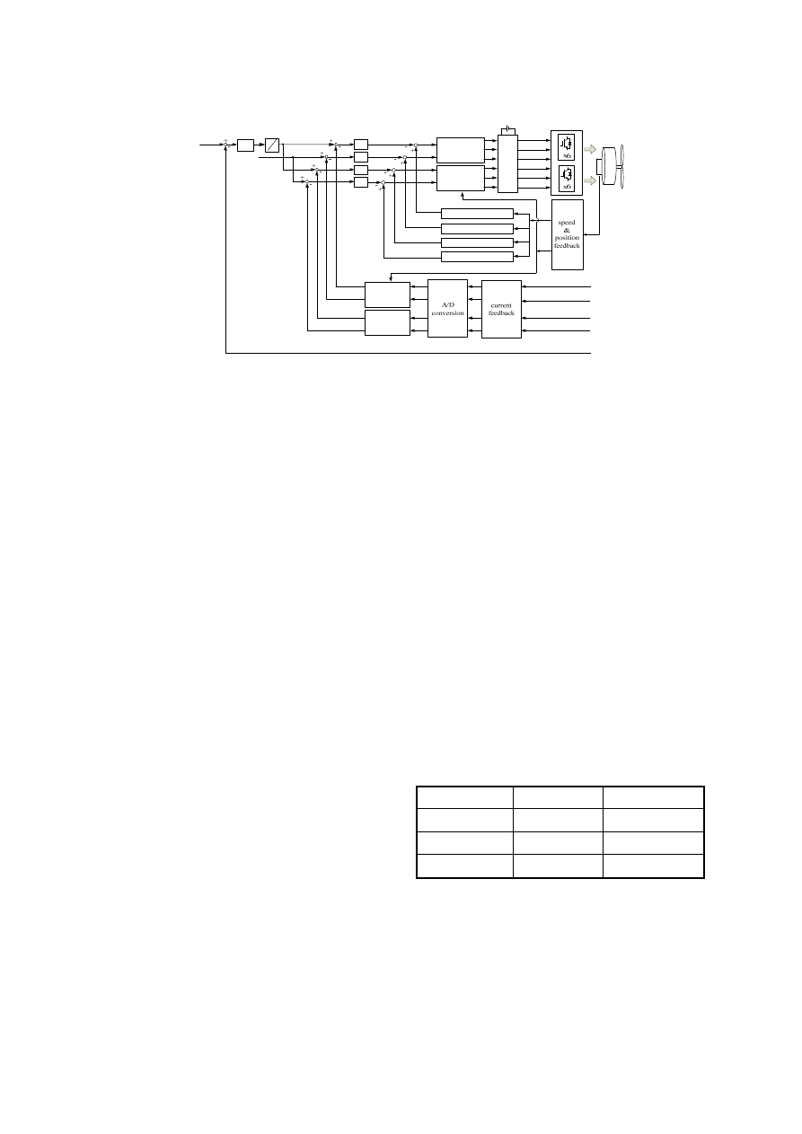
. Based on the above strategy, a control system of
the 6-phase ac-to-dc power converter is proposed in
Fig. 4. The dual three-phase synchronous
transformation matrices depicted in the figure are the
interface between control and feedback signals, and
they synchronously vary with the rotation speed of
the generator. The matrices
,
can be obtained from
substituting
and
for
1
r
q
i
2
r
q
i
0
0
€
€
( ),
(
30 )
qd
r
qd
r
T
T
θ
θ −
o
1
1
0
0
€
€
( ),
(
30 )
qd
r
qd
r
T
T
θ
θ
−
−
−
o
€
r
θ
€ 30
r
θ
°
−
x
in the
following equations:
0
1
1
cos
cos(
120 ) cos(
240 )
2
( )
sin
sin(
120 ) sin(
240 )
3
1
1
1
2
2
2
cos
sin
1
( )
cos(
120 ) sin(
120 ) 1
cos(
240 ) sin(
240 ) 1
qd
qdo
x
x
x
T
x
x
x
x
x
x
T
x
x
x
x
x
°
°
°
°
−
°
°
°
°
⎡
⎤
⎥
⎥
⎥
⎥
⎥
−
−
⎢
⎢
=
−
−
⎢
⎢
⎢
⎣
⎦
⎡
⎤
⎢
⎥
=
−
−
⎢
⎥
⎢
⎥
−
−
⎣
⎦
*
2
d
(45)
From the transformed current signals in synchronous
frame, the output commands
,
,
, and
are calculated by the proportional-integral
controllers for the PWM output.
*
1
q
v
*
1
d
v
*
2
q
v
v
C. Storage System
In order to maintain power balance between the
wind-driven generator and loads under varying wind
speed, a storage system consisting of buck/boost
choppers and battery sets is installed at the dc-link.
When the output power of the wind generator system
is larger than the loads, the dc chopper is operated in
the buck mode to transfer residual power to the
battery. Reversely, it is operated in the boost mode to
replenish the deficit in generator output power.
III. Experimental Results
This paper completes the system prototype
according to the system proposed in Fig. 1 with the
specifications:
z Number of poles of permanent magnet
synchronous generator: 22
z Rated power: 1 kW
z Rated current: 20 A
z Rated rotation speed: 1000 rpm
z Capacitance of the dc-link: 3300 μF
z Inductance
B
L
of dc chopper: 0.5 mH
z Sampling period: 100 μs
In order to verify the stability and reliability of the
proposed system, experiments are conducted on
loading and no-load operations under constant as
well as varying rotation speeds for the proposed
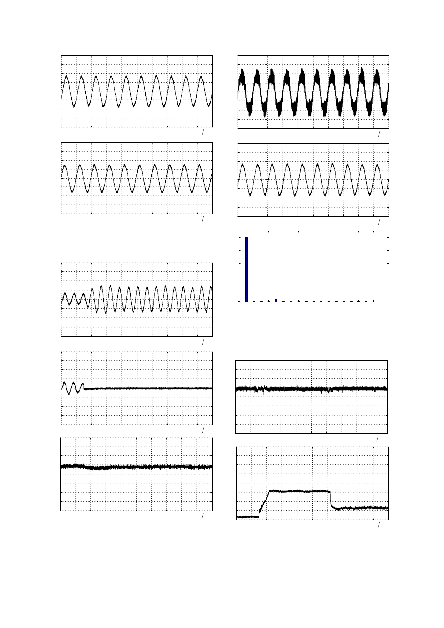
system. Fig. 5 shows a phase difference of 30 degree
between the currents and
a
i
x
i
, which meets the
design of the presented generator architecture. To
evaluate the reliability of the overall system, Fig. 6
shows the transient and steady-state currents
and
a
i
x
i
of generator output, when winding x-y-z/rectifier
x-y-z fails. Under this circumstance, dc-link voltage
remains constant as can be seen from Fig. 6. At 550
rpm and a full-load of 768W, Fig. 7 shows the
voltage, current and corresponding current harmonic
spectrum in the steady-state. The total harmonic
distortion of current is only 3.59%, and the power
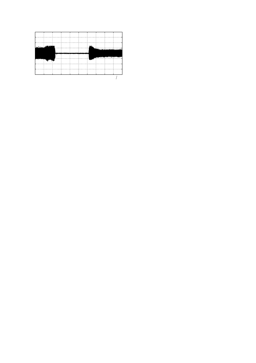
factor is close to unity. Finally, to test the dynamic
response, a servo-motor is used to simulate the
varying wind speed. The rotation speed of the
generator is dropped from 500 to 0 rpm, and then
increased from 0 to 400 rpm. The results in Fig. 8
shows that this wind generator system is capable of
providing a stable power, which is unaffected by the
wind speed.
IV. Conclusions
This paper presents the generation system, which
integrates the 6-phase PMSG, the 6-phase ac-to-dc
power converter, and the buck/boost choppers in
order to supply a stable dc power under varying wind
speed. The magnetic circuit analysis is conducted for
the proposed 6-phase generator by Magsoft Flux2D,
4/7
and the corresponding mathematic model are used
r
ω
ˆ
r
θ
a
i
b
i
x
i
y
i
1
dc
v
,
a
a
T
T
+
−
,
b
b
T
T
+
−
,
c
c
T
T
+
−
,
x
x
T
T
+
−
,
y
y
T
T
+
−
,
z
z
T
T
+
−
SPWM
1
ˆ
( )
qdo
r
T
θ
−
1
0
ˆ
(
30 )
qdo
r
T
θ
−
−
ˆ
( )
qdo
r
T
θ
0
ˆ
(
30 )
qdo
r
T
θ −
1
q
i
2
q
i
1
d
i
2
d
i
*
1
q
i
*
2
q
i
*
*
1
2
0
d
d
i
i
=
=
*
*
*
1
2
dc
dc
dc
v
v
v
=
=
1
dc
v
*
1
q
u
*
1
d
u
*
2
d
u
*
2
q
u
*
1
q
v
*
1
d
v
*
2
q
v
*
2
d
v
vdc
G
1
iq
G
1
id
G
2
iq
G
2
id
G
1
r
s d
r
m
L i
ω
ω λ ′
−
+
2
r
s d
r
m
L i
ω
ω λ ′
−
+
1
r
s q
L i
ω
2
r
s q
L i
ω
a
i
b
i
x
i
y
i
, ,
A B Z
1
2
dc
v
Fig. 4 The control block diagram of the 6-phase ac-to-dc power converter.
for the parameter calculations of the equivalent flux
linkages, the stator equivalent resistance, and the
winding inductors. The resulted parameters help the
proposed 6-phase ac-to-dc power converter build the
dynamic equations for the system control. The
control of the rectifier with dual three-phase
coordinate transformation simplifies the control
parameter design, and improves the system dynamic
response.
The experiments on a full-load of 768 W are given
to justify the design and the analysis of the proposed
generator. Loading and reliability evaluation are
conducted to show the excellent performance of the
system. The experimental results reveal high power
factor and low harmonic distortion with efficiency of
90%, thereby verifies the practicality of the proposed
6-phase wind generation system.
References
[1] F. Wang, Z. Wenpeng, Z. Ming and W. Baoguo,
“Design considerations of high-speed PM
generators for micro turbines,” International
Conference on Power System Technology, vol.
1, 2002, pp. 158-162.
[2] M. K. Kazimierczuk, “Analysis and design of
buck/boost zero-voltage-switching resonant
dc/dc convertor,” IEE Proceedings of Circuits,
Devices and Systems, vol. 136, 1989, pp.
157–166.
[3] F. Wang, M. Zong, W. Zheng and E. Guan,
“Design features of high speed PM machines,”
Sixth International Conference on Electrical
Machines and Systems, vol. 1 , 2003, pp. 66-70.
[4] Z. Cunshan and T. Feng,”Research on
improving permanent magnetic generator output
characteristic,” Fifth International Conference
on Electrical Machines and Systems, vol. 2,
2001. pp. 850-852.
[5] E. Muljadi, C. P. Butterfield and Y.-H. Wan,
“Axial-flux modular permanent-magnet
generator with a toroidal winding for
wind-turbine applications,” IEEE Transactions
on Industry Applications, vol. 35, no. 4, 1999,
pp. 831–836.
[6] S. M. A. Sharkh, D. Morris, S. R. Turnock, L.
Myers and A. S. Bahaj, “Performance of an
integrated water turbine PM generator,”
International Conference on Power Electronics,
Machines and Drives, 2002, pp. 486–491.
[7] C. Mademlis, I. Kioskeridis and N. Margaris,
“Optimal Efficiency Control Strategy for
Interior Permanent-Magnet Synchronous Motor
Drives,” IEEE Transactions on Energy
Conversion, vol. 19, 2004, pp. 715–723.
[8] E. Cengelci and P. Enjeti, “Modular PM
generator/converter topologies, suitable for
utility interface of wind/micro turbine and
flywheel type electromechanical energy
conversion systems,” IEEE Industry
Applications Annual Conference Record, vol. 4,
2000, pp. 2269-2276.
[9] N. Bianchi, S. Bolognani and F. Luise,
“Potentials and Limits of High-Speed PM
motor,” IEEE PESC’04, vol. 1, 2004, pp.
458-463.
Acknowledgement
The authors wish to express their sincerely
appreciation to Nation Science Council for
supporting this research with grant NSC
94-2213-E-011-069.
Table 1 Operation mode of the proposed converter
Switch status
Operation mode
Dc-link voltage
1
2
:
,
:
S
on S
off
Serial mode
1
2
dc
dc
dc
v
v
v
=
+
1
2
:
,
:
S
off S
on
Parallel mode
1
2
dc
dc
dc
v
v
v
=
=
1
2
:
,
:
S
off S
off
Converter off
0
dc
v
=
5/7
-40
-30
-20
-10
0
10
20
30
40
(
)
10
time
ms div
( )
a
-40
-30
-20
-10
0
10
20
30
40
( )
x
(
)
10
time
ms div
( )
b
Fig. 5 Phase difference of output currents from phase
a and phase x: (a)phase current
; (b)phase current
a
i
x
i
.
-40
-30
-20
-10
0
10
20
30
40
( )
(
)
20
time
ms div
( )
a
-40
-30
-20
-10
0
10
20
30
40
(
)
20
time
ms div
( )
b
0
10
20
30
40
50
60
70
80
(
)
20
time
ms div
( )
c
Fig. 6 Reliability evaluation under one generator
winding and/or its corresponding rectifier outage at
500 rpm and a load of 256W: (a)phase current
;
(b)phase current
a
i
x
i
; (c)dc-link voltage
.
dc
v
-40
-30
-20
-10
0
10
20
30
40
(
)
10
time
ms div
( )
a
-40
-30
-20
-10
0
10
20
30
40
(
)
10
time
ms div
( )
b
g (
0
20
40
60
80
100
)
THD= 3.59%
Harmonic order
0
2
4
6
8
10
12
14
16
18
20
(c)
Fig. 7 Experimental results under rotor speed of 550
rpm and resistive load of 768 W: (a)output voltage
, (b)phase current
; (c)current harmonic
spectrum of
.
a
v
a
i
a
i
0
10
20
30
40
50
60
70
80
(
)
2
time s div
( )
a
0
5
10
15
20
25
30
35
40
(
)
2
time s div
( )
b
6/7
-40
-30
-20
-10
0
10
20
30
40
(
)
2
time s div
( )
c
Fig. 8 Dynamic test results under varying wind
speed: (a)dc-link voltage
; (b)output current of
the battery set
; (c)output current of the generator
.
dc
v
B
i
a
i
7/7
Wyszukiwarka
Podobne podstrony:
Development of wind turbine control algorithms for industrial use
Advanced Methods for Development of Wind turbine models for control designe
H Infinity State Feedback Control for a Class of Networked Cascade Control Systems With Uncertain De
Development of a highthroughput yeast based assay for detection of metabolically activated genotoxin
Core Wall Survey Control System for High Rise Buildings
Microprocessor Control System for PWM IGBT Inverter Feeding Three Phase Induction Motor
Foresight analysis of wind power in Turkey
(eolica) II PRINCIPLES OF A WIND POWER TURBINE?HAVIOUR(1)
Microprocessor Control System for PWM IGBT Inverter Feeding Three Phase Induction Motor(1)
Munster Application of an acoustic enhancement system for outdoor venues
Simulation of a PMSM Motor Control System
Foresight analysis of wind power in Turkey
Microprocessor Control System for PWM IGBT Inverter Feeding Three Phase Induction Motor(1)
0 Principles of a Wind Power Turbine Behaviour
Miller Recent Developments In Slab A Software Based System For Interactive Spatial Sound Synthesis
więcej podobnych podstron