
Initial Print Date: 12/04
Table of Contents
Subject
Page
Central Locking and Soft Close Automatic Doors . . . . . . . . . . . . . . . . . .6
System Overview . . . . . . . . . . . . . . . . . . . . . . . . . . . . . . . . . . . . . . . . . . . . . . .7
Car Access System (CAS) . . . . . . . . . . . . . . . . . . . . . . . . . . . . . . . . . . . . . . .8
Door Modules . . . . . . . . . . . . . . . . . . . . . . . . . . . . . . . . . . . . . . . . . . . . . . . . . .9
Power Module . . . . . . . . . . . . . . . . . . . . . . . . . . . . . . . . . . . . . . . . . . . . . . . . . .9
Door Lock Assemblies . . . . . . . . . . . . . . . . . . . . . . . . . . . . . . . . . . . . . . . . .10
Trunk lock Actuator and Soft Close Drive Assembly . . . . . . . . . . . . . . .10
Engine-Hood Contact . . . . . . . . . . . . . . . . . . . . . . . . . . . . . . . . . . . . . . . . . .11
Fuel Tank Filler Door Actuator . . . . . . . . . . . . . . . . . . . . . . . . . . . . . . . . . . .11
Central Locking Button (CLB) . . . . . . . . . . . . . . . . . . . . . . . . . . . . . . . . . . .11
Passenger Compartment Trunk Lid Release Button (TOEHKI). . . . . . .11
Outside Trunk-Lid Release Button (TOEHK). . . . . . . . . . . . . . . . . . . . . .12
Hotel Switch . . . . . . . . . . . . . . . . . . . . . . . . . . . . . . . . . . . . . . . . . . . . . . . . . .12
Central Locking System Functions . . . . . . . . . . . . . . . . . . . . . . . . . . . . . .13
Central Locking . . . . . . . . . . . . . . . . . . . . . . . . . . . . . . . . . . . . . . . . . . . . .13
Double Locking . . . . . . . . . . . . . . . . . . . . . . . . . . . . . . . . . . . . . . . . . . . . .13
Selective Unlocking . . . . . . . . . . . . . . . . . . . . . . . . . . . . . . . . . . . . . . . . .13
Double Unlocking with Valid Remote Control . . . . . . . . . . . . . . . . . . .13
Double Unlocking via Central Lock Button (CLB) . . . . . . . . . . . . . . .13
Electric Lock-Out Protection . . . . . . . . . . . . . . . . . . . . . . . . . . . . . . . . .14
Crash Unlocking . . . . . . . . . . . . . . . . . . . . . . . . . . . . . . . . . . . . . . . . . . . .14
Reactivation of Controls after Crash Unlocking . . . . . . . . . . . . . . . . .14
Timed-Arrest . . . . . . . . . . . . . . . . . . . . . . . . . . . . . . . . . . . . . . . . . . . . . . .15
Initiation of Convenience Closing/Opening . . . . . . . . . . . . . . . . . . . . .15
Signalling to Anti-Theft Alarm System (via CAN) . . . . . . . . . . . . . . . .16
Vehicle and Key Memory Individualization . . . . . . . . . . . . . . . . . . . . . .16
Soft Close Automatic Doors (SCA) . . . . . . . . . . . . . . . . . . . . . . . . . . . .17
Timed Arrest Circuit . . . . . . . . . . . . . . . . . . . . . . . . . . . . . . . . . . . . . . . . .17
E65 Central Body Electronics
Revision Date:

Subject
Page
Emergency Close . . . . . . . . . . . . . . . . . . . . . . . . . . . . . . . . . . . . . . . . . . .22
Phase 1 . . . . . . . . . . . . . . . . . . . . . . . . . . . . . . . . . . . . . . . . . . . . . . . . . . .22
Phase 2 . . . . . . . . . . . . . . . . . . . . . . . . . . . . . . . . . . . . . . . . . . . . . . . . . . .22
Convenience Opening/Closing . . . . . . . . . . . . . . . . . . . . . . . . . . . . . . .23
Closing . . . . . . . . . . . . . . . . . . . . . . . . . . . . . . . . . . . . . . . . . . . . . . . . . . . .23
Opening . . . . . . . . . . . . . . . . . . . . . . . . . . . . . . . . . . . . . . . . . . . . . . . . . . .23
Child Lock-out . . . . . . . . . . . . . . . . . . . . . . . . . . . . . . . . . . . . . . . . . . . . . .24
Motor Protection (thermal protection) . . . . . . . . . . . . . . . . . . . . . . . . . . . .24
Load Deactivation . . . . . . . . . . . . . . . . . . . . . . . . . . . . . . . . . . . . . . . . . . . . .24
Undervoltage Deactivation . . . . . . . . . . . . . . . . . . . . . . . . . . . . . . . . . . . . . .24
Smooth Start-up . . . . . . . . . . . . . . . . . . . . . . . . . . . . . . . . . . . . . . . . . . . . . .25
Smooth Rundown . . . . . . . . . . . . . . . . . . . . . . . . . . . . . . . . . . . . . . . . . . . . .25
Synchronous Motor Operation . . . . . . . . . . . . . . . . . . . . . . . . . . . . . . . . . .26
Blocking Protection . . . . . . . . . . . . . . . . . . . . . . . . . . . . . . . . . . . . . . . . . . . .26
Anti-Trapping Protection . . . . . . . . . . . . . . . . . . . . . . . . . . . . . . . . . . . . . . . .26
Manual Initialization . . . . . . . . . . . . . . . . . . . . . . . . . . . . . . . . . . . . . . . . . . . .27
Electric Roller Sun Blinds . . . . . . . . . . . . . . . . . . . . . . . . . . . . . . . . . . . . . . .28
System Overview . . . . . . . . . . . . . . . . . . . . . . . . . . . . . . . . . . . . . . . . . . . . . .28
Sunroof Cassette . . . . . . . . . . . . . . . . . . . . . . . . . . . . . . . . . . . . . . . . . . . . .32
SHD Control Unit . . . . . . . . . . . . . . . . . . . . . . . . . . . . . . . . . . . . . . . . . . . . . .33

Subject
Page
Sunroof Switch . . . . . . . . . . . . . . . . . . . . . . . . . . . . . . . . . . . . . . . . . . . . . . . .33
Vehicle Bus Interface . . . . . . . . . . . . . . . . . . . . . . . . . . . . . . . . . . . . . . . . . .34
Adjustment of Anti-trapping Protection to the Vehicle Speed . . . .36
Emergency Mechanical Operation . . . . . . . . . . . . . . . . . . . . . . . . . . . . . . .36

4
E65 Central Body Electronics
E65 Central Body Electronics
Model: E65/E66
Production: All
After completion of this module you will be able to:
• Understand the Operation of Body Electronics Systems
• Understand the Role of Bus Networks in Body Electronics Systems
• Locate and Identify Components used in Body Electronics Systems
• Diagnose Concerns in Body Electronic Systems

Introduction
The Central Body Electronics functions of the E65 are to a large extent identical to the
ZKE III centralized system of the E38. To enhance convenience and safety, numerous
technical modifications and innovations have been carried out. A large proportion of
these improvements are executed in the background and are not immediately noticed by
the customer.
A major difference to the E38 is the placement of software for a particular function. The
software can be located in the associated control unit or distributed to several control
units. On account of this distribution, each system is described below mainly in its
capacity as a function.
The following functions are classified as "Central Body Electronics" of the E65:
• Central Locking and soft-close automatic doors
• Power windows
• Roller sun blinds
• Sun roof
• Front seat adjustment
• Steering-column adjustment
• Memory seats, door mirrors, steering column
• Windshield wipe-wash functions
• Automatic trunk lid lift
5
E65 Central Body Electronics

Central Locking and Soft Close Automatic Doors
The Central Locking system (ZV) of the E65 controls the:
• Door locks (optional soft-close).
• Trunk lid lock and soft close.
• Fuel tank filler flap locking.
Various improvements have been made to the system, however the greatest change from
the previous model is that while the CAS contains the Central Locking Master functions,
the output operations are de-centralized and carried out by several different modules.
The Central Locking may be operated from the following locations:
• Lock cylinder, driver's door.
• Remote Control (FZV function of FBD).
• Central locking button (CLB).
• Passenger compartment trunk lid release button (TOEHKI).
• Trunk-lid button, inside of trunk lid (TOEHKK, only if equipped with HKL).
• Outside trunk-lid button (TOEHK).
• Hotel switch in lockable compartment in center console (hotel).
Unlocking via the crash sensor and forced double unlocking via the "key-inserted signal"
in the Car Access System (CAS) and the central locking button are possible.
The following central-locking functions can be controlled by way of the operating loca-
tions:
• Locking
• Double locking
• Selective unlocking
• Unlocking
• Soft close (optional for the doors)
In order to improve anti-theft security, the lock cylinder in the trunk lid is now only used
for mechanical emergency unlocking.
The individual components communicate with each other via the K-CAN P and with the
rest of the vehicle via the K-CAN S (e.g. anti-theft alarm system).
The FZV is connected by way of a separate unidirectional line to the CAS control unit.
6
E65 Central Body Electronics
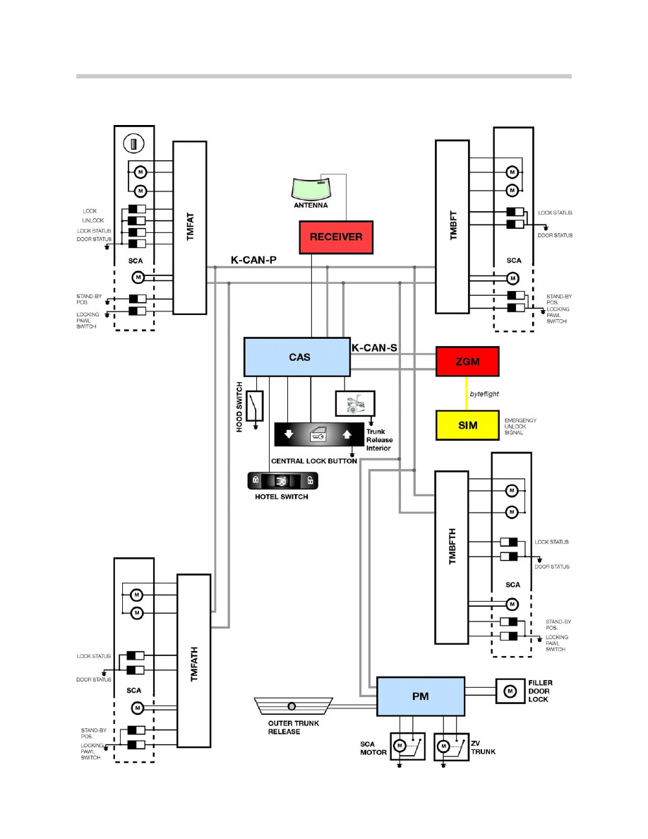
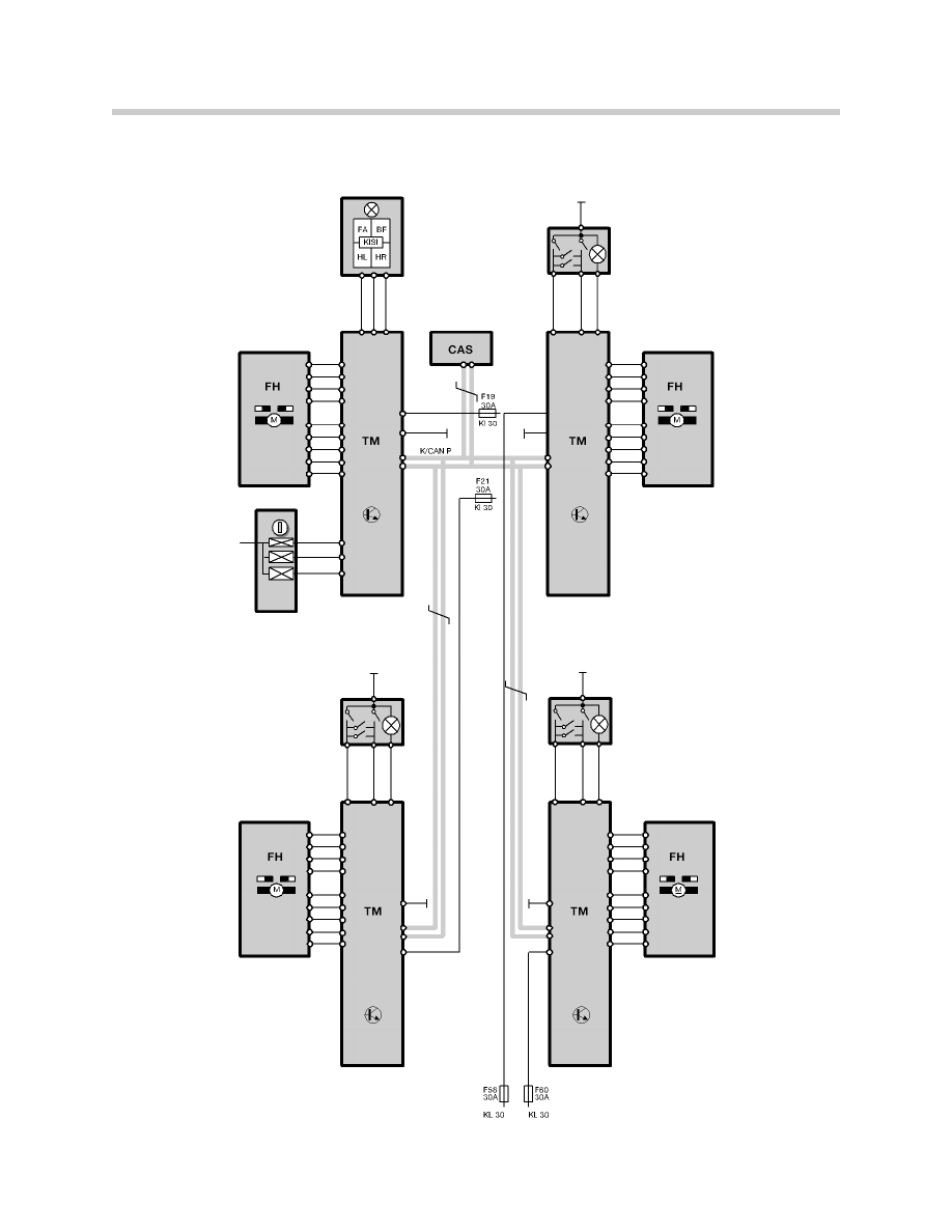
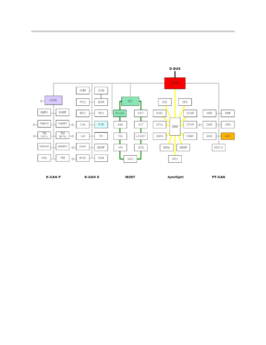
System Overview
7
E65 Central Body Electronics
Components
The Central Locking system of the E65 consists of the following components:
• Car Access System module (CAS).
• Door Modules (4).
• Power Module.
• Door lock assemblies.
• Trunk lock actuator and soft close drive assembly.
• Engine hood contact.
• Fuel tank filler door actuator.
• Central locking button (CLB).
• Passenger compartment trunk lid release button (TOEHKI).
• Trunk-lid button, inside of trunk lid (TOEHKK, only if equipped with HKL).
• Outside trunk lid release button (TOEHK).
• Hotel switch in lockable compartment of the center console (hotel).
Car Access System (CAS)
As Central Locking Master (ZV master), the CAS
controls all the higher-level functions of the Central
Locking system.
It centrally monitors the battery voltage of the ZV
(lock actuators) assemblies.
The ZV assemblies function within a voltage range of
9 V to 16 V.
Activation of the ZV assemblies is controlled as fol-
lows:
• For safety reasons, the "crash unlocking" function is activated independently of the
battery voltage.
• If the CAS determines a value less than 9 V or greater than 16 V, there is no forward-
ing or implementation of operator prompts by the CAS.
• The motors in the doors are blanked out based on the evaluation of the local voltage
at the door modules (motors for Soft Close Automatic and motors for electric open-
ing).
8
E65 Central Body Electronics
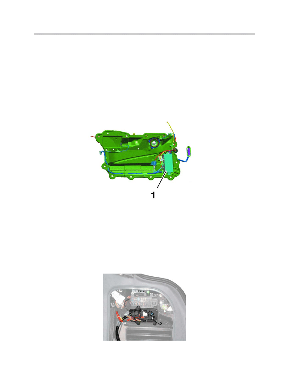
Door Modules
Each door contains a door module (1) for the control of all functions contained or
attached to the door. The door module is located inside of the door attached to the
inner door carrier.
The door modules receive the signals for locking and un-locking requests from the
CAS over the K-CAN-P.
The door modules are also responsible for interpreting the signals from the hall
sensors in the door lock assemblies and providing them to the CAS.
The output for the ZV drives is controlled by internal final stages.
Power Module
Within the Central Locking system the Power Module is responsible for the output
control of the trunk lock actuator, soft close motor and the fuel filler flap actuator.
The Power module is also responsible for relaying the signals:
• Status of the trunk lid open/closed
• Status of the outside trunk lid button
• Status of timed-arrest for the trunk and filler flap ZV drives
9
E65 Central Body Electronics
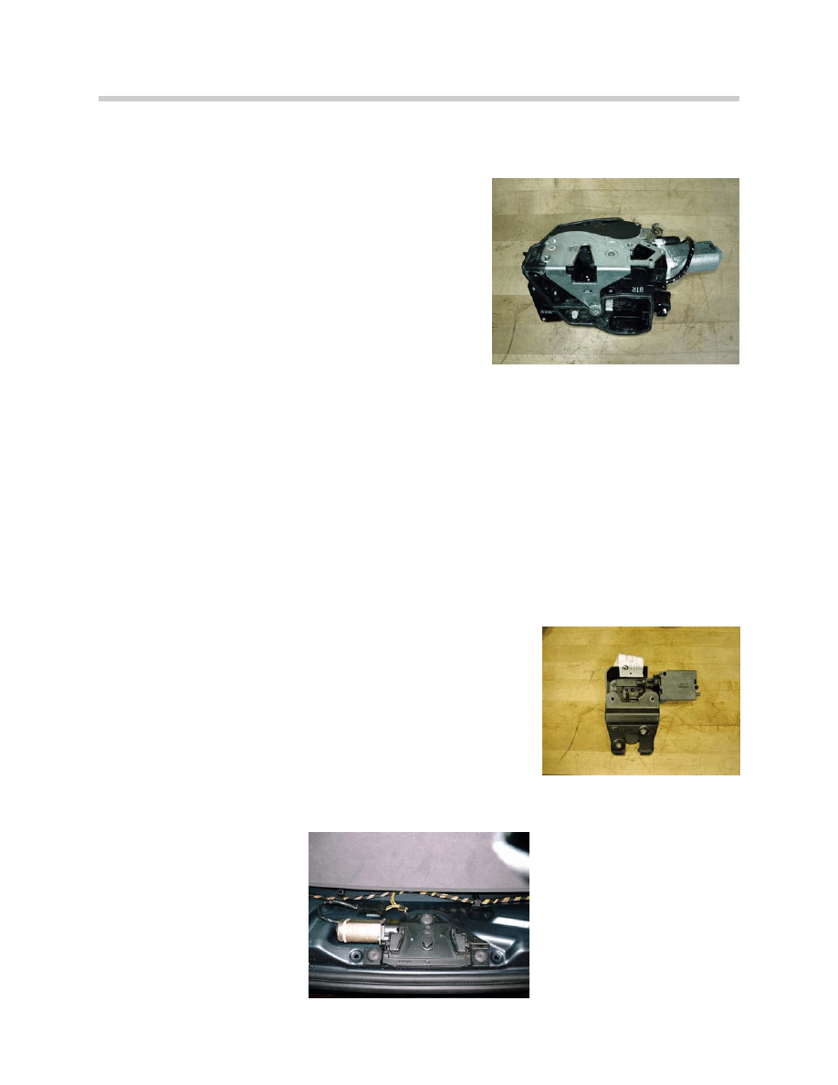
Door Lock Assemblies
The door lock and ZV drives consist of a single inte-
grated unit. The door lock assembly contains two
servo motors, the locking mechanism and hall sen-
sors for position sensing. The hall sensors signal:
• Door contact (open or closed)
• Position of mechanical lock (locked/ unlocked)
If the vehicle is equipped with the optional soft close
doors there is an additional motor for pulling the door
closed as well as two more hall sensors. The hall
sensors signal:
• “Stand-by” position
• “Locking pawl switch” position
The Drivers lock assembly contains two hall sensors for the signalling of the position of
the external lock cylinder in the drivers door. The hall sensors signal:
• Unlock request
• Lock request
The rear doors are equipped with child lock out switches preventing the rear doors from
being opened from the inside.
Trunk lock Actuator and Soft Close Drive Assembly
The trunk lock and trunk lock actuator are two separate com-
ponents. The lock actuator is controlled by the PM and con-
tains a micro-switch to signal the lock status of the trunk.
This input is sent via the K-CAN-P to the CAS for the moni-
toring of the trunk (e.g. DWA, CC)
The signal is also an input to the PM to run the soft close
motor and to control the trunk lights.
The soft close motor is carried over from the E38. It contains
an internal micro-switch to signal the PM that the motor has
completed 1800 of rotation.
10
E65 Central Body Electronics
Engine-Hood Contact
The engine-hood contact is a simple ground (N/O) contact. This contact is closed when
the hood is open and is monitored for the purposes of theft prevention and CC messages
(Check Control). The status is distributed by the CAS to the vehicle electrical system.
Fuel Tank Filler Door Actuator
The assembly for unlocking and locking the fuel tank filler door is operated by the Power
Module. The commands for this purpose are controlled by the ZV master (CAS). The
fuel-tank flap is only locked with ZV central double locking (ZS).
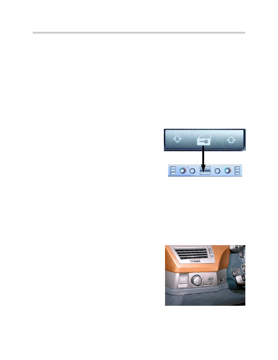
Central Locking Button (CLB)
The Central Locking button is located in the iDrive
Comfort Area as part of the IHKA control panel.
However, the CLB is not processed by the IHKA,
it has a direct connection to the CAS.
The button is a rocker switch that provides two sepa-
rate signals; one for unlock and another for lock. The
signal provided is a momentary ground.
The operation of the CLB remains the same as the
previous E38:
• Central locking/unlocking of the doors
(the fuel filler flap remains open).
• Removing a vehicle from double lock to
central lock (emergency function)
Passenger Compartment Trunk Lid Release Button (TOEHKI).
The interior trunk release button is located in the
iDrive Driving Area to the left of the steering column.
It provides a momentary ground signal to the CAS
when pressed.
The signal is passed on to the PM over the K-CAN-P.
The button is active from KL R when the hotel setting
is off and the vehicle speed is below 2mph.
11
E65 Central Body Electronics
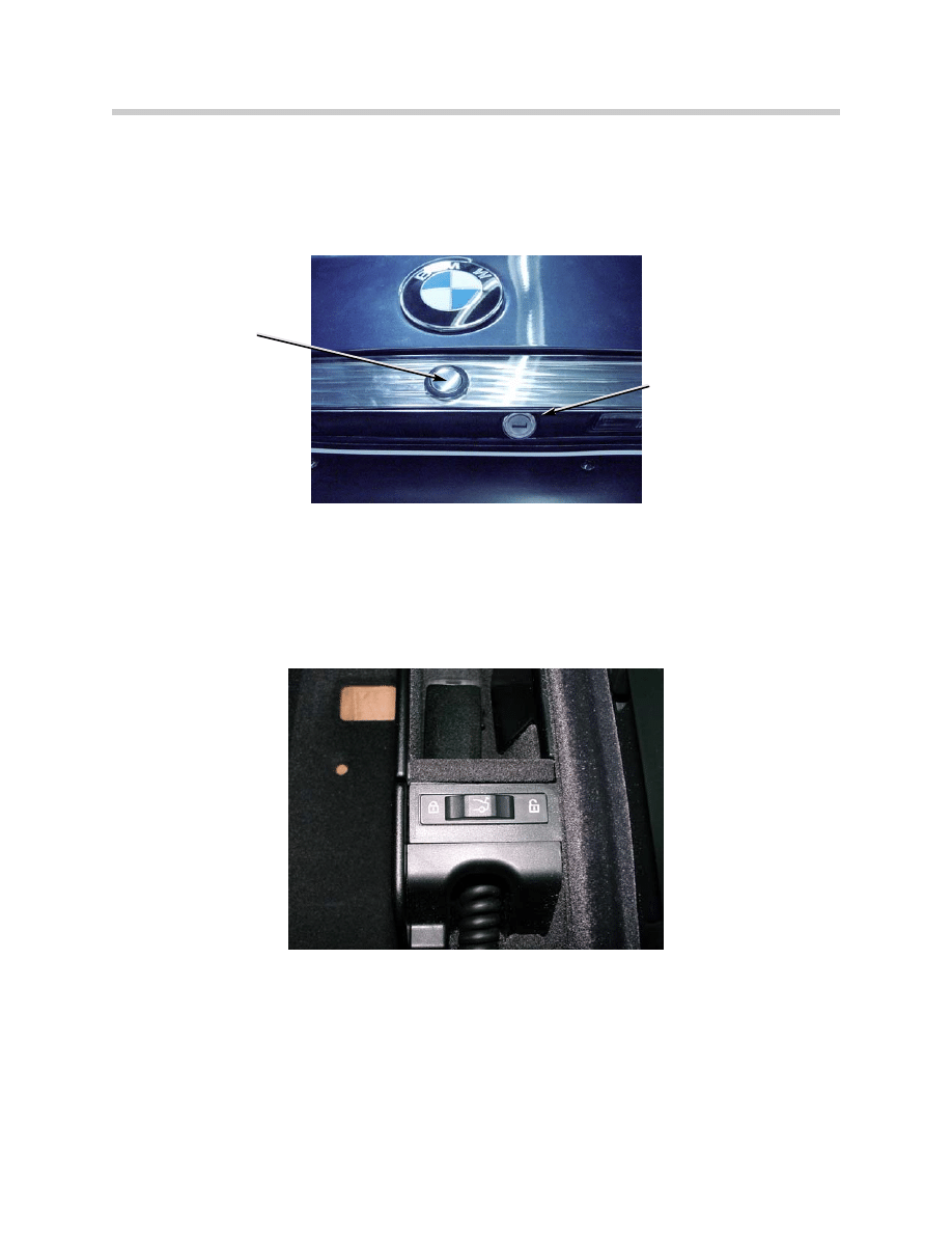
Outside Trunk-Lid Release Button (TOEHK).
The outside trunk lid release button is a direct input to the Power Module. It provides a
momentary ground when pressed.
The button is active when the vehicle is unlocked and the hotel setting is off.
Hotel Switch
The Hotel switch is located inside of the lockable compartment of the center console.
It is a direct input to the CAS as a ground signal when the switch is in the “lock” position.
Locking of the compartment is done using the mechanical key integrated into the
Remote Control which the customers then takes with them. Only the “electronic key”
is then handed over to the hotel valet.
When the setting is “locked”, the interior and outside trunk release button inputs
are ignored.
The CAS sends the telegram over the bus that the hotel setting is engaged. This is
used,for example, by the DWA to continue to monitor the trunk and the hood even
though the vehicle is unlocked.
12
E65 Central Body Electronics
Release button
on trunk lid
Emergency lock cylinder

Principle of Operation
Central Locking System Functions
Central Locking
Central locking is activated using the Central Locking button inside of the vehicle. Only
the doors and trunk are locked, the fuel tank filler door remains open for access by gas
station attendants. The locking pin in the door lock assembly is not disengaged, there-
fore the vehicle doors may be unlocked by pulling on the interior handle once.
Double Locking
When double locking is engaged, the locking pin in each door is disengaged from the
lock by a mechanical coupling. It is no longer possible to unlock the vehicle from the
inside using the handles or from the outside. The fuel-tank filler door is locked.
Double locking is only possible with terminal OFF and the subsequent opening of one of
the front doors and with the driver's door closed. With the driver's door open, there is no
action in response to the double locking operator request.
Selective Unlocking
Selective unlocking is activated by means of coding. With selective unlocking, only the
driver's door is unlocked on the first unlocking command via the driver's door operating
location or the remote control. The other doors move into the locked position. Only with
the second unlocking attempt is the entire vehicle unlocked.
Double Unlocking with Valid Remote Control
With the vehicle double locked, the assemblies are moved from the "double locking"
position to the "locked" position when a valid Remote Control is inserted in the CAS. The
vehicle engine may only be started when the central locking has been double-unlocked.
The procedure is handled by the K-CAN messages for the central locking control system.
If a driver has unintentionally locked himself inside his vehicle by means of the Remote-
Control , forced double unlocking prevents him from driving off in the vehicle while it is
double-locked and the anti-theft alarm system is armed.
Double Unlocking via Central Lock Button (CLB)
An occupant who has accidentally locked himself in is able to get out by operating the
CLB. This action moves the ZV on a one-off basis from double locked to locked. It is
then possible to open the door through double operation of the inside door handle.
The DWA is not disarmed in this process so that when a vehicle is opened in this way
an alarm cycle is triggered when the door is opened.
13
E65 Central Body Electronics

Electric Lock-Out Protection
With electric lock-out protection, the electronics ensures that the central-locking assem-
bly is unlocked again e.g. when the locking knob is pressed down with an open driver's
door. This protects the driver against being inadvertently locked out. With the driver's
door open, it is not possible to lock the vehicle with the central lock button. The remote
control is likewise ineffective.
Crash Unlocking
The crash message is transmitted from the Safety Information Module (SIM) via the ZGM
to the K-CAN-S. The CAS receives the message and passes it on over the K-CAN-P.
The message is made available to the door modules and the Power Module. A priority
"unlocking message" is simultaneously created by the ZV master in the CAS and for-
warded to the door modules and the Power Module. This is to ensure that the system is
unlocked in each case even if the crash message were to be delayed because of a a cur-
rently active message. Unlocking of the Central Locking system in the event of a crash is
only permitted under the following conditions:
• Terminal R ON
• Terminal 15 ON
• Vehicle is not in double-locked state (for theft protection).
Reactivation of Controls after Crash Unlocking
The following component signals are disabled after crash unlocking to prevent unwanted
re-locking due to crash-induced short-circuit faults or damage of the lock mechanism:
• Lock cylinder, driver's door
• CLB
• Remote Control
These components are re-activated by resetting the CAS-internal crash status. After ter-
minal R "OFF", the following events can reset the crash status after 3 s:
• Reception of signals "status, crash severity" value 0 (light collision without airbag
activation)
• Opening and closing of driver's door
• Unlocking command at lock cylinder in driver's door
• Unlocking command via Remote Control
• Deactivation and reactivation of terminal R
14
E65 Central Body Electronics

Timed-Arrest
An timed arrest circuit is provided because the assembly motors are always operated up
to their stops. An internal counter is increased by a value of 1 each time it is actuated.
This counter is reduced by a value of 1 after a specified period of time.
The timed arrest circuit engages if the counter exceeds a specified value on account of
permanent actuation. All the operator prompts for the Central Locking are forwarded but
no longer executed.
The door modules and the Power Module signal via the K-CAN P to the Central-Locking
master in the CAS that an assembly is now in timed arrest status. The ZV master in the
CAS then outputs an overall status "ZV assembly, timed arrest circuit" for all the users.
The timed arrest circuit is disengaged by the door modules and the Power Module when
the signal "ZV assembly, timed arrest circuit" is removed. There is also an timed arrest
circuit for trunk-lid unlocking. The anti-repeat circuit is ignored during the crash unlocking
function.
Initiation of Convenience Closing/Opening
The Central Locking system includes the convenience function for power windows and
sliding sunroof. It is possible by means of the lock cylinder in the driver's door or by
Remote Control to initiate sequential closing (only from drivers door) and opening of the
windows and the sunroof as long as terminal R is off.
Convenience closing is initiated if a ZS (double-lock) command is held for an extended
period. The sequence is aborted if the ZS command is cancelled during the closing
operation. If a ZS command is entered again within a specific period since the cancella-
tion, the sequence starts after a brief period.
Convenience opening is initiated if an ER (unlock) command is held for an extended peri-
od. The sequence is aborted if the ER command is cancelled. In the event of resump-
tion, convenience opening follows the same process as convenience closing.
The Central Locking system forwards the operator prompts to controlling functions in the
CAS (power-window master) and to the vehicle bus system.
15
E65 Central Body Electronics

Signalling to Anti-Theft Alarm System (via CAN)
The DWA is not part of the Central Locking system but it does require commands and
signals from it. For this purpose, the DWA monitors the status of doors, hood, trunk and
terminal status.
The DWA monitors the tilt sensor and the ultrasonic interior protection sensor by itself.
The DWA is armed by each valid locking (ZS) command. Optical feedback is provided by
an LED, which signals the status of the DWA. The tilt and interior sensors are deactivat-
ed if a ZS command is initiated again within a specific period (10 s) after the first arming
of the DWA.
The CAS forwards this information to the K-CAN P and K-CAN S. The DWA is disarmed
by each double-unlocking command. The luggage compartment can also be accessed
while the DWA is armed via remote control without the alarm being activated.
The alarm is activated if the trunk lid is opened mechanically using the emergency lock
cylinder while the DWA is armed.
Scope of DWA monitoring from the Central Locking system:
• Door contacts
• Engine-hood contact
• Trunk-lid contact
• Tampering, driver's-door lock cylinder
Vehicle and Key Memory Individualization
All the codable functions for Vehicle/Key Memory are activated within the framework
of the E65 Coding, Individualization and Programming program (CIP).
These functions can be set using the coding software and are stored in the CAS.
They only become active when the vehicle has been "double-locked".
The following central locking functions have been made possible for individualization
(4 keys + 1 vehicle coding):
• Selective unlocking of driver's door.
• Automatic locking from a speed of 16 km/h (10mph).
• Automatic relocking if vehicle unlocked by remote control and no ensuing action
in 2 minutes.
16
E65 Central Body Electronics

Soft Close Automatic Doors (SCA)
The Soft Close Automatic Doors are optional equipment (part of the convenience pack-
age). The drive assemblies are integrated into the door locks and are controlled by the
individual door modules.
There are 2 additional hall sensor signals for the position detection of the SCA drive:
1) “Stand-by” position
2) “Locking pawl switch” position
• The control system always knows the position of the drive and can, if necessary,
activate it in order to move it to a defined or “set” position.
• The "Locking pawl switch" position is set each time the drive is switched on and
deleted again when switched off in a set position (stand-by or park). The "Stand-by”
position" is set when the door is opened and deleted when the latch has reached
the park position.
• When the door is opened, (recognized by the rotary-latch hall sensor), the SCA drive
moves into the stand-by position so that it only needs to move half a turn into the
park position the next time the door is pulled closed. If the door is moved into the
main catch before the SCA is in operation (slamming shut), the SCA drive remains
in the stand-by position. The SCA does not move the next time the door is opened.
• When the door is closed, the sensors identify the catch position from the locking-
pawl signal and pull the door into the main catch. The SCA drive then remains in the
park position.
• If the electronics fails to identify the reaching of the two defined positions, the control
system assumes a timeout after 5 seconds and shuts down the SCA drive. An entry
is also made in the fault memory of the respective door module.
• The stop conditions are checked every 23 ms while the SCA is in operation. The
motor is shut down if the SCA is not stopped within 5 seconds. The motor is
switched off when reaching the park position.
Timed Arrest Circuit
The SCA doors have a timed arrest circuit to prevent the motors and final stages from
overheating. Operation is staggered until the arrest counter in the door modules returns
to zero.
17
E65 Central Body Electronics

Power Windows
The power windows are controlled by the door modules, (i.e. one door module locally
controls one power window). The CAS control unit controls the window functions as
the power-window master.
The master controls the convenience functions and the Central locking (ZV) interface.
List of power window functions:
• Closing and opening of windows.
• Toll function (one-touch) in both directions on all 4 windows.
• Child lock-out.
• Emergency close.
• Convenience opening/closing.
• Timed arrest circuit.
• Excessive load cutout.
• Smooth rundown / smooth startup.
• Synchronous motor operation.
• Anti-trapping protection.
18
E65 Central Body Electronics
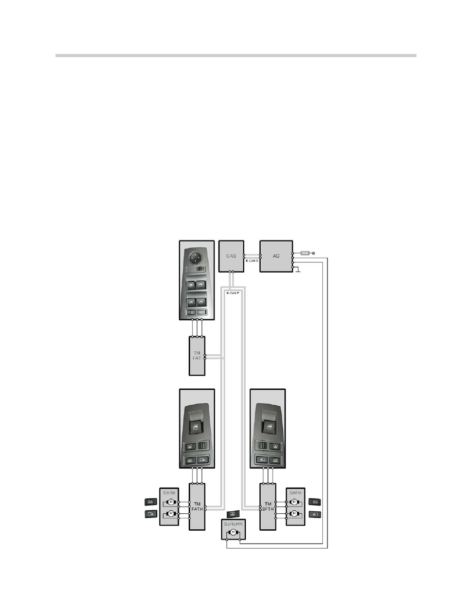
System Overview
19
E65 Central Body Electronics
Components
Car Access System (CAS)
The CAS contains the master functions of the power window system. It is also responsi-
ble for signalling the convenience open/closed requests.
Electric Window Lift Assemblies
The electric window lift assemblies consist of an electric motor/module with integrated
hall sensors for distance and speed sensing. The anti-trap strips in the door frame of the
predecessor E38 have been deleted. The module integrated into the assembly receives
the control requests from the door module via a PWM signal, it then provides the appro-
priate voltage to control the operation of the motor within an infinitely variable speed
range up to full voltage. The window motor/modules must be initialized.
The window regulators are of the cable operated design as used in the E38.
Door Modules
Each door contains a door module for the control of all functions contained or attached to
the door. The door module is located inside of the door attached to the inner door carrier.
The door module receives the control requests from the window switches and carries out
the allowed operation of the motor. The control is based on the status signalled from the
CAS and the current condition of the window as detected by the hall sensors in the
motor assembly.
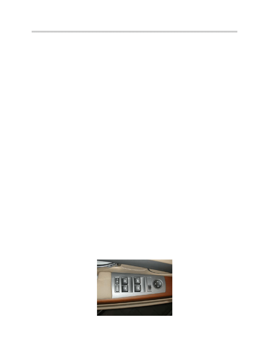
Window Switches
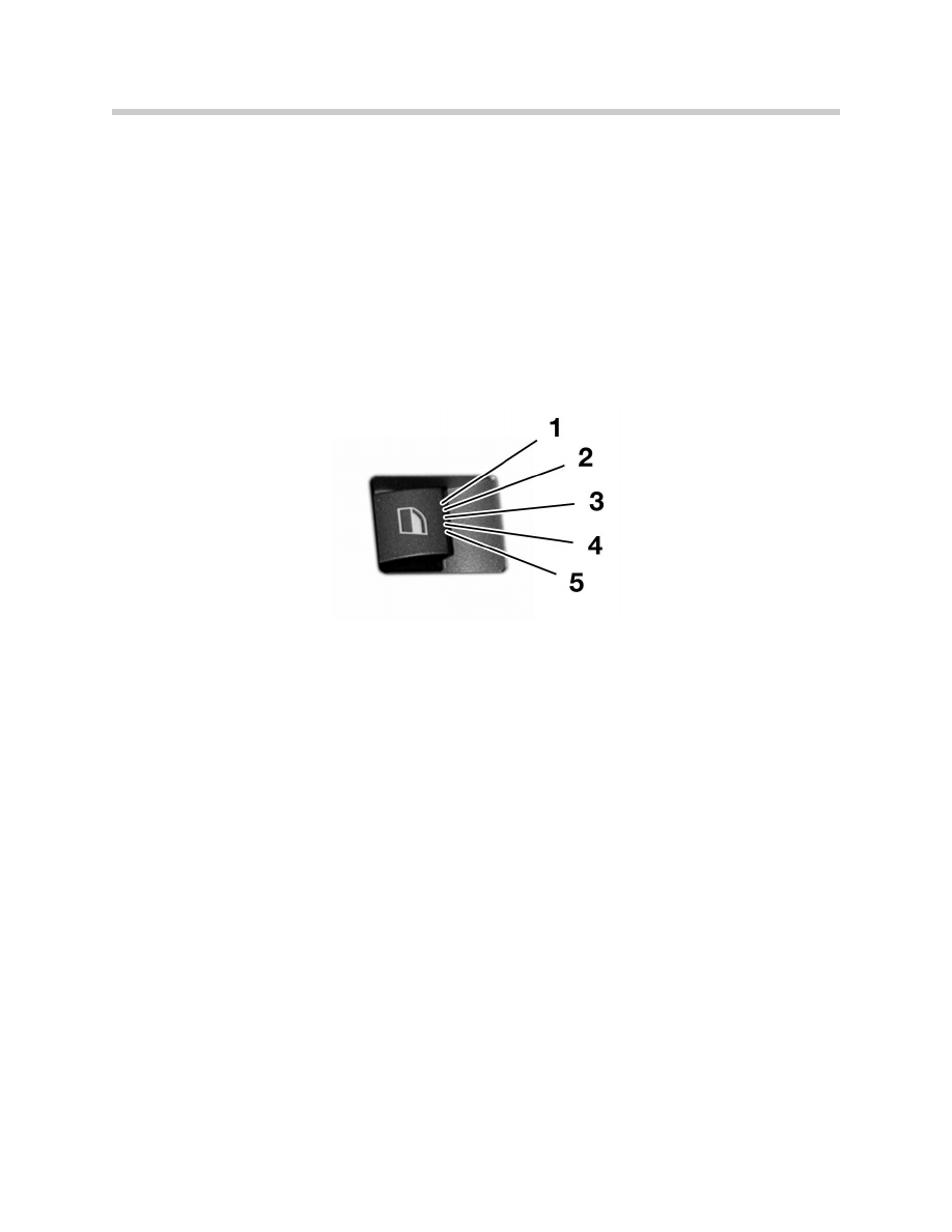
The window switches of the E65 are of the press/pull type as first seen on the E46. The
drivers door switch block is a control unit that communicates with the door module via a
local P-bus (single wire: 9.6kbps).
The drivers door module signals the status of all of the switches of the drivers switch
block to the other door modules and the CAS over the K-CAN-P.
The single switches in the passenger doors are conventional ground switches that
communicate 5 statuses over 2 wires as used on the predecessor E38.
20
E65 Central Body Electronics
Principle of Operation
Operating the Windows
The power windows are enabled and disabled by the power-window master in the CAS.
Enabling and disabling are dependent on coding and the status of the door contacts and
the terminal status.
The power windows can be operated from "terminal R on" and are disabled in the
crossover into "sleep mode".
The switch control logic, which was introduced for the first time in the E46, is also used
in the E65. This prevents the windows from being closed by mistake.
Toll operation (one-touch) takes place in the closing or opening direction immediately
after the switch position "one touch closed" or "one-touch open" has been reached. The
power windows are activated in the initial closed/open lock-in positions as long as the
button is held in this position. Anti-trapping protection is active in both one-touch and
manual operation.
The function with the highest priority that is started or selected first is executed.
However, a one-touch function can be cancelled by the local switch.
In order to prevent damage to the motor, the window travel is subject to a maximum acti-
vation time of 10 s (exception: initialization run).
If the window glass moves to the upper stop, the drive is activated at full power for the
blocking time of 0.5 s in order to ensure safe closing.
The following functions are available thanks to timed activation of the power-window dri-
ves by means of power final stages:
• Smooth startup
• Smooth rundown
• Speed control (2 speed stages)
21
E65 Central Body Electronics
1. One touch closed
2. Manual close
3. Neutral
4. Manual open
5. One touch open

Emergency Close
This function is used for deliberate closing of the windows without anti-trapping protec-
tion. Use of this function may be necessary for example in the event of an attack from an
outside source or closing a window glass which has frozen solid.
The entire control sequence is divided into two phases:
Phase 1
The emergency-close mode is activated after 0.5 s when the position "one-touch
closed" is held. The window is closed at maximum speed and with modified anti-trap-
ping protection. Releasing the button terminates emergency closing, (i.e. the window
proceeds to be closed with full anti-trapping protection as with automatic operation).
Anti-trapping protection remains activated in modified form even during emergency clos-
ing. If trapping is detected, the window travels back only the short distance of 20 mm.
This relieves strain on the mechanical system or gives the attacker the option of backing
away.
Phase 2
The button must now be released ("zero position") and then pressed again in the position
"overpressed closed" within 4 s. The window is now closed without anti-trapping protec-
tion with full force. In the event of blocking, the window is powered until the motor ther-
mal protection is activated or the window has moved to the upper stop.
Emergency closing is terminated when the button is released. For safety reasons, it is
always possible to open the window independently of the thermal protection.
If there is no renewed activation of the emergency-close mode within 4 s (overpressing
and holding), anti-trapping protection returns to its normal state. "Emergency close" is
not operational from a vehicle speed of > 16 km/h (10mph).
When the child lock is engaged, the emergency-close function cannot be activated by
the local switches in the rear doors but only only by the switch block in the driver's door.
An emergency-closing operation activated by the switch block in the driver's door cannot
be interrupted by the local buttons in the front passenger door or the rear doors.
The emergency-close function can be completely deactivated by means of coding.
22
E65 Central Body Electronics

Convenience Opening/Closing
The convenience function enables the operator to close or open all the windows and the
slide/tilt sunroof before entering or leaving the vehicle.
The convenience opening function can be triggered by means of the Remote Control
key. Both convenience opening and closing can be operated by mechanical key opera-
tion in the driver's door lock.
The function is controlled by the power-window master in the CAS control unit. For this
purpose, a K-CAN-P message is sent from the CAS to the four doors.
Closing
The closing operation starts after a delay; for this purpose, the key must be held in the
locking (VR) or double locking (ZS) position during the entire closing operation. The clos-
ing operation can be terminated at any time by turning the key back. The sequence
begins again after 0.5 s if a ZS command is entered again within 3 s of the cancellation.
The individual windows and the sunroof are closed in the following sequence: rear power
windows (PWs), front PWs and sunroof. The PWs are activated so that two PWs are
always switched on simultaneously (starting with the rear). The front PWs are started
after a 1 s delay. The sunroof is closed immediately when all 4 windows are closed or 3.5
s after the start of convenience closing.
Opening
In the unlocking lock cylinder position (ER), it is possible to initiate convenience opening
by holding the key in this position. With convenience opening, first the front PWs are
opened, followed by the rear PWs after a delay of 1 s. The sunroof is opened immediately
when all 4 windows are open or 3.5 s after the start of convenience opening.
The operation can be terminated at any time by turning the key back. The sequence
begins again after 0.5 s if an ER command is entered again within 3 s of the cancellation.
Operation by Remote Control is performed in the same way as operation by lock cylinder.
23
E65 Central Body Electronics

Child Lock-out
Operation of the two rear power-window buttons is disabled by means of the child-lock
button in the switch block in the driver's door. When the child lock is engaged, it is only
possible to operate the rear power windows from the driver's switch block or via the con-
venience function. An LED in the button indicates the current status of the child lock.
The LED is activated by the power-window master in the CAS. No opening/closing func-
tion is triggered when the child lock is engaged.
In the event of a fault, the Check Control message "Child lock not functioning" in the
instrument cluster is sent by the CAS.
It is only possible to deactivate the child lock in conjunction with a valid Remote Control
in the ignition.
The child lock remains engaged after a CRASH telegram has been received.
Motor Protection (thermal protection)
Each power-window motor is provided with its own thermal protection to prevent them
from overheating. For this purpose, the motor running time is added up in a counter. The
output value of the counter is influenced by the ambient temperature.
If the counter exceeds a threshold, new control requests are no longer accepted but a
movement that is already in process is continued. The counter is reduced again if the
motor is deactivated. Operator prompts are accepted again when the value drops below
the threshold. Return window travel in the event of trapping is not obstructed by the ther-
mal protection.
Load Deactivation
In order to assist starting, the power windows are not operational with terminal 50 (starter
motor). Each action, e.g. opening or one-touch function, is terminated immediately and
the power windows are stopped. Following the starting sequence, the windows are fully
operational again once they have been re-actuated.
Undervoltage Deactivation
The supply voltage is monitored locally in the door modules. If the supply voltage is
below 9 V, the power windows are disabled.
24
E65 Central Body Electronics
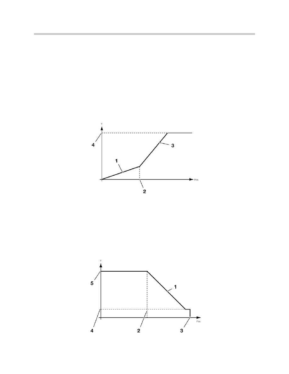
Smooth Start-up
Smooth start-up describes a new feature of the E65 which starts the power windows
with a linear increase in speed up to full speed. Smooth start-up takes place in both the
closing and opening directions.
Clunking noises are avoided in the door due to the low speed as play in the window lift
assembly is taken up.
To ensure that the windows remain quiet during the entire service life of the vehicle, the
gradient of the first ramp is less steep than that of the second ramp. The total window
travel until the full desired speed is reached is approximately 5 mm.
Smooth Rundown
Smooth rundown describes running down of the power windows with a linear decrease
in the infinitely variable speed until the window is at a standstill. This function is used
when approaching the end positions (in both automatic and manual operation) of the
lower and upper stops.
The smooth-rundown travel is about 15 mm on the downward travel and about 30 mm
on the upward travel.
25
E65 Central Body Electronics
1. First gradient ramp
2. Distance traveled
during first ramp
3. Second gradient ramp
4. Full run speed
1. Rundown gradient ramp
2. Start of rundown
3. End position
4. Speed in window seal area
5. Full run speed

Synchronous Motor Operation
The window speed is kept constant over a wide voltage range by timed activation (PWM)
of the power windows.
Blocking Protection
Blocking protection is based on monitoring of the Hall-sensor signals. With each signal
change of the active sensor, a time measurement is restarted which triggers the blocking
reaction when a defined period of time is exceeded (exception: emergency close).
If blocking protection takes place in an adjustment range protected by closing-force limi-
tation, the window travels back when the closing-force limitation is exceeded. Outside
this range, the window travels back for 1/4 turn in order to relieve the tension on the
mechanical system.
Anti-Trapping Protection
Anti-trapping protection restricts window closing force to a maximum permissible value
(closing-force limitation). Any load in excess of this force causes the window to immedi-
ately stop and reverse.
The power windows require an initialization procedure during the initial startup.
The initialization procedure consists of:
• Standardization
• Learning of characteristic closing-force curve
When the window is standardized, the end positions of the window travel are determined
by a blocking run in the upper window seal and on the lower window stop. When the
closing force is being learned, it is measured over the entire closing travel and perma-
nently stored.
Anti-trapping protection is active and one-touch closing is possible only after initialization
has been completed.
Calibration of the triggering threshold begins with a closing force of approx. 500 N. This
high starting value increases operational reliability so that the windows are closed even in
the event of stiffness.
26
E65 Central Body Electronics
Manual Initialization
The power-window system must always be initialized after any repair work affecting the
system has been carried out.
Operation sequence:
• Press the power window switch in the open direction for at least 15 seconds but
no longer than 25 seconds.
• Release the switch and then pull it to the “one-touch” close position and hold it.
Initialization begins (this step is part of the CAS logic to prevent a trigger of the
initialization mode if the switch is jammed).
• Hold the switch in the “one-touch” close position until initialization is completed.
The windows will open and then return to the closed position to confirm a success-
ful initialization.
• A Check Control message is issued if any of the side-windows are not initialized.
The message is retracted as soon as all windows are successfully initialized.
27
E65 Central Body Electronics
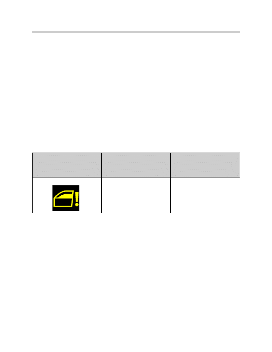
Check Control message
displayed in Kombi
Message displayed in
Control Display
Cause
Power window not initialized!
“Power window not initialized!” Anti-
trap protection deactivated. Please
contact the nearest BMW center.
One or more windows have not been
detected by the CAS as not initialized.
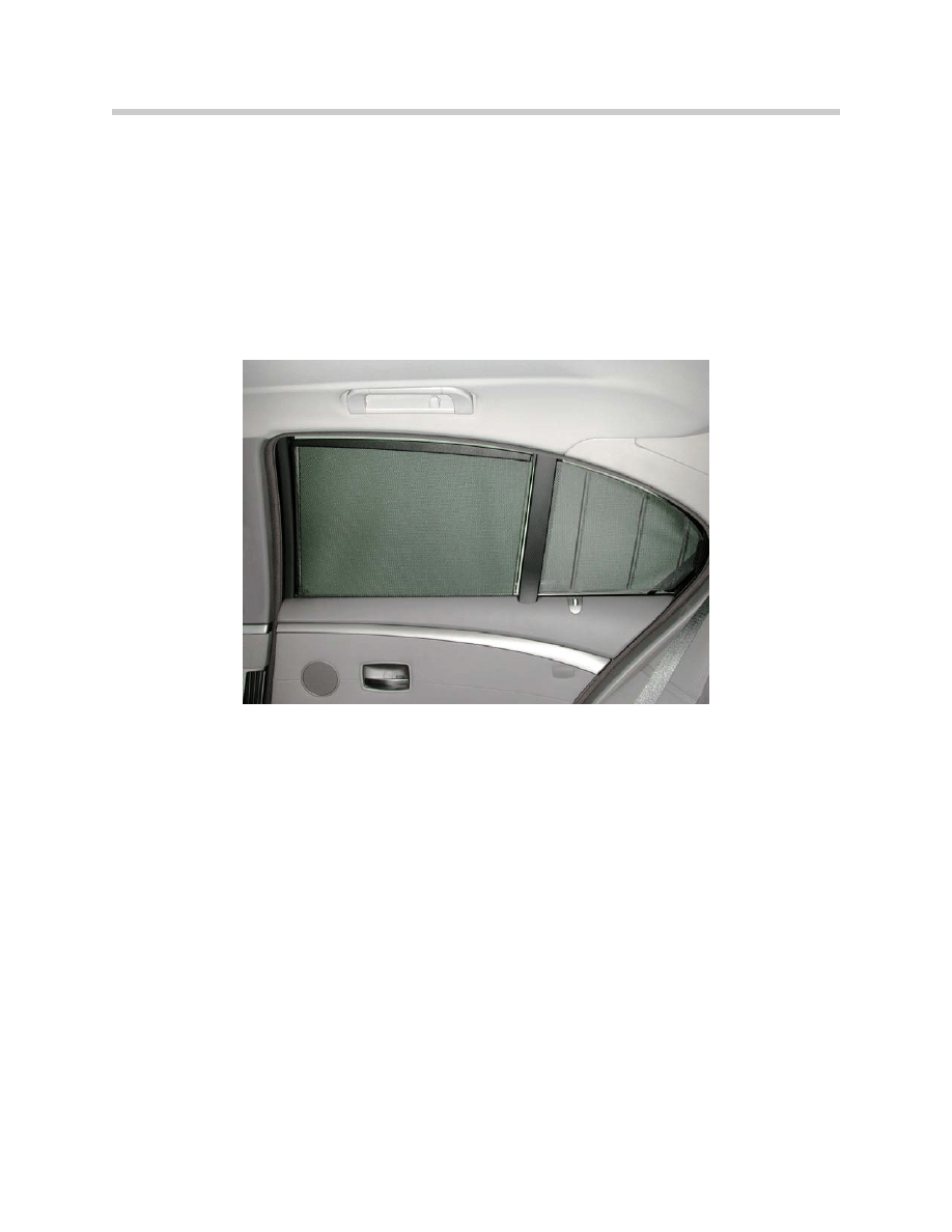
Electric Roller Sun Blinds
Rear electric roller sun blinds are optional equipment. They are only available in combina-
tion with the rear-window roller blind. Each door has two roller sun blinds: one for the
side window and one for the quarter window.
The IHKA contains the master function and the rear-window roller blind control. The
operating switches for the rear electric roller sun blinds are located in the driver's door
switch block (module) and on the rear switch blocks (module).
There are buttons for the side-window sun blind, the quarter window sun blind, the rear-
window roller blind and left/right rear door side selections on each door switch block .
Both rear door modules contain control outputs and master functions for the rear-com-
partment roller sun blinds.
System Overview
28
E65 Central Body Electronics
Principle of Operation
To protect the customer against trapping, the side-window roller blinds can only be raised
when the side window is closed. The system regards the side window as "closed" up to a
maximum opening of 10 mm.
• It is always possible to lower the side window roller blinds, even when the window
is open.
• It is always possible to lower the window glass, even when the side-window roller
blind is up.
When the window is open and a command to raise the side-window roller blind is sent,
the side-window roller blind starts up briefly and reverses . This indicates that an invalid
operation has been attempted. The roller sun blind cannot be raised until the customer
closes the window. It is always possible to operate the quarter roller blind, irrespective of
the side window position.
Briefly pressing or holding down the control buttons for the side and rear-window roller
blinds initiates an automatic movement of the roller sun blinds as far as the top or bottom
stop.
The left/right slide switches on the rear switch blocks are used to select whether the
roller sun blinds and the side window on the left or right hand side are to be operated.
Holding down the rear window roller blind switch activates a special function, which acti-
vates the rear-window roller blind immediately. After 750 ms, all rear-compartment roller
sun blinds move in the same direction as the rear-window roller blind.
For example, when the rear-window roller blind is down, both the rear-window roller blind
and the rear-compartment roller sun blinds move upwards when the button is held down.
29
E65 Central Body Electronics

Undervoltage Protection
The voltage supply is monitored locally in the door modules. Roller sun blind operation is
stopped if the voltage is less than 9.0 V. The functions are not available again until the
voltage exceeds 9.5 V.
Once a roller sun blind has been set in motion, the operation is completed regardless of
the voltage level.
Blockage Detection
To protect the motor and the control units, the door module has blockage detection
which switches the motor off after it reaches the upper or lower end position. The deacti-
vation criteria is calculated from the motor starting current. When 75% over the normal
motor starting current is reached the control unit switches off the motor.
Motor activation is also time monitored. The system stops activating the motors after 11
s for the rear and side-window roller blinds and 6 s for the quarter window roller sun blind.
Timed Arrest
To prevent playing children from overloading the motor by constantly sending commands
(thermal cutout), a timed arrest feature used. If this counter exceeds a maximum running
time of 90 seconds, then no new operating requests will be accepted. If running time of
the motor exceeds 90 seconds, the motor operation pauses 270 seconds.
When timed arrest is active, it is possible to reverse the roller sun blind once downward.
Child Safety Lock
The child safety lock function is engaged or released via a button in the driver's door
switch block. When the child safety lock is engaged, it not possible to operate the rear
compartment roller sun blinds and the rear-window roller blind from the rear switches.
An active roller sun blind function is not interrupted by engaging the child safety lock.
30
E65 Central Body Electronics
Sunroof (SHD)
Introduction
The SHD module controls the opening, closing, lifting and lowering of the glass sunroof
in the E65.
The anti-trapping protection of the sunroof has been improved considerably.
The following functions are available for the sunroof:
• Manual operation
• One-touch operation
• Convenience opening and closing
• Panic close
• Anti-trapping protection
• Emergency operation
• Mechanical operation
• Generation of CC messages
• Diagnosis
System Overview
31
E65 Central Body Electronics
Components
The sunroof consists of the following components:
• Sunroof cassette
• SHD Control unit
• Sunroof switch
• Vehicle bus interface
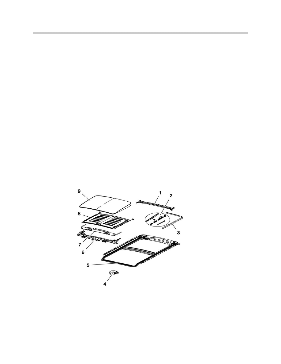
Sunroof Cassette
The structure of the sunroof cassette is similar to that of the E38/E39.
The parts that can be replaced with the cassette still installed in the vehicle are:
• Glass panel
• Floating headliner
• Wind deflector
• SHD module
• Roof gutter
The cables of the sunroof cassette cannot be serviced individually, if they are defective,
the entire cassette must be replaced. If the sliding/tilt lever is damaged the cassette
must also be replaced.
Note: Be careful removing the rubber drain hoses from the cassette because
they are bonded to the body and are not easily replaced.
32
E65 Central Body Electronics
1.
Roof gutter
2.
Mechanism
3. Edge trim
4. SHD
module
5. Sunroof recess
6. Bracket for cables
7.
Wind deflector
8.
Floating headliner
9.
Glass panel
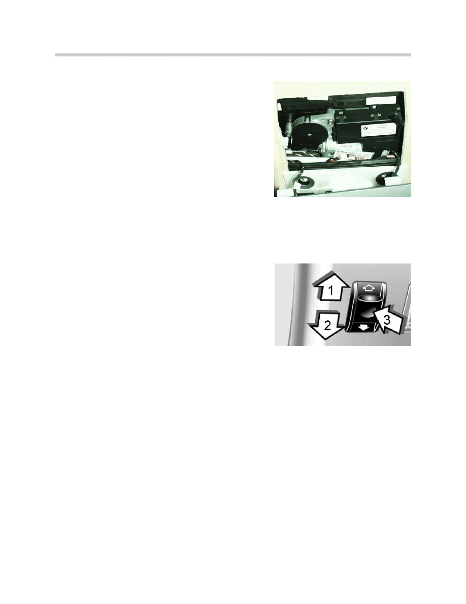
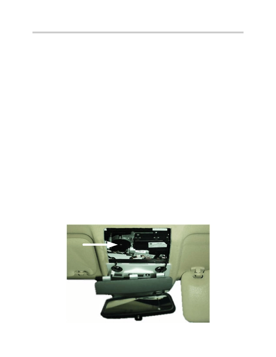
SHD Control Unit
The sunroof module is located, as with other models,
behind the rear view mirror in the center of the roof.
It contains the following components:
• DC motor with attached gear reduction
mechanism.
• 2 integrated Hall sensors for position and trap
detection.
• Control unit
The DC motor is controlled with a PWM signal to
provide a smooth-rundown feature similar to the
window operation.
This module can only be replaced as a complete unit.
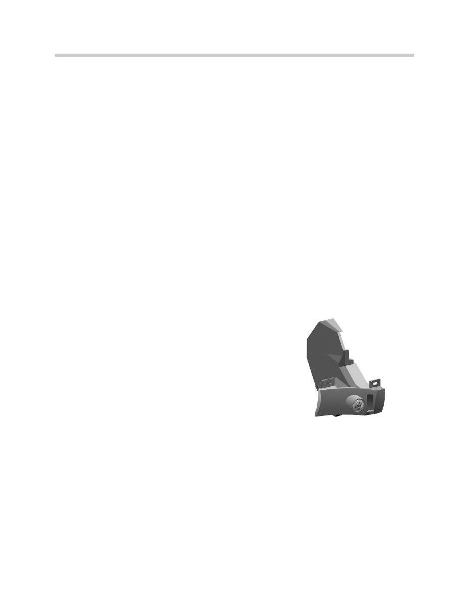
Sunroof Switch
The switch is installed in the panel behind the interior
light, beside the emergency call button.
Possible directions for movement:
1. Open
2. Close
3. Lift
The operations available from the sunroof switch
correspond to the previous E38.
The sunroof switch provides the SHD module with requests for sunroof operation as
coded grounds over three wires. The ground supply for the switch is from the SHD
control unit.
33
E65 Central Body Electronics
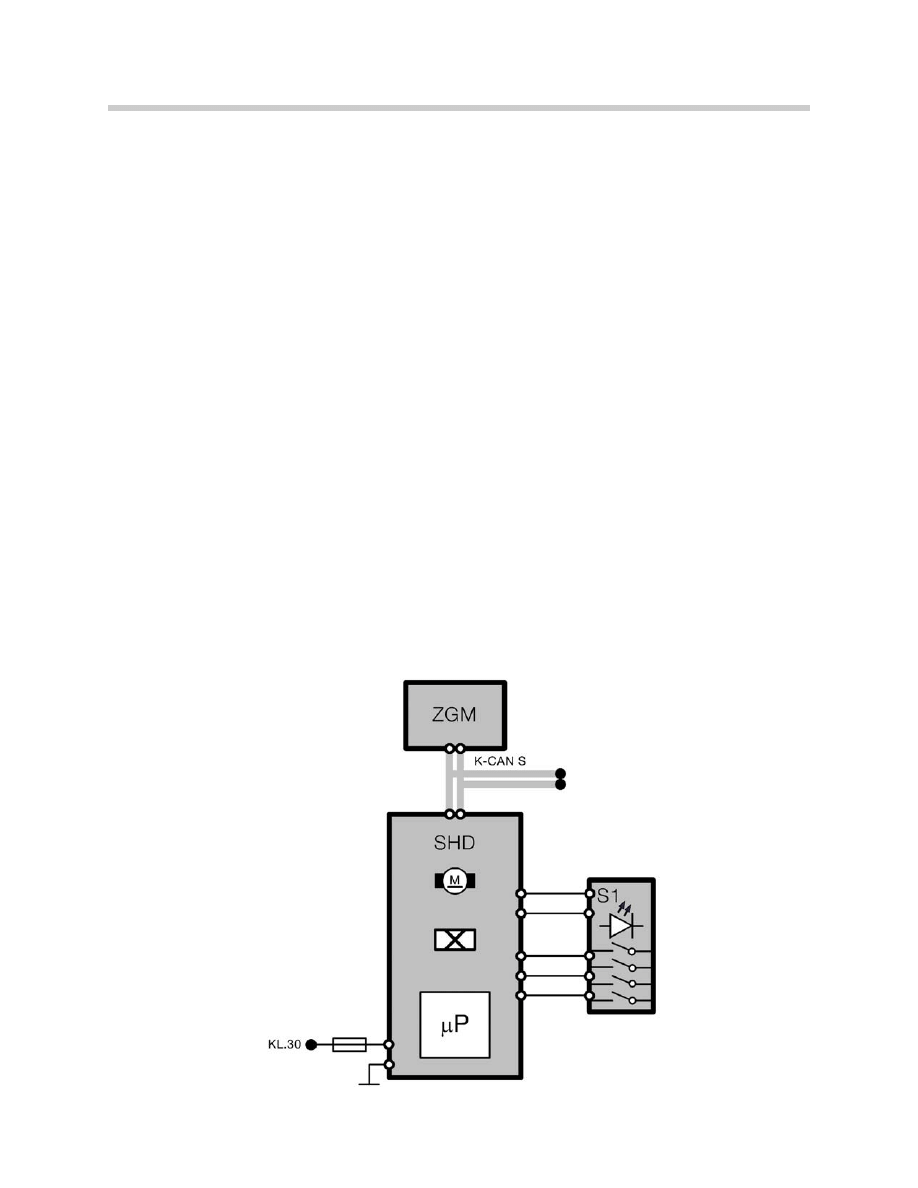
Vehicle Bus Interface
The communication with the vehicle electronics is via the K-CAN-S connection.
CAS
The convenience opening/closing commands and the terminal status are received from
the CAS via the K-CAN S.
Instrument Cluster
The instrument cluster serves as a display of Check Control (CC) messages for the SHD.
Control Display CD
Extended CC messages are displayed in the CD.
Dynamic Stability Control DSC
The DSC provides the speed signal over the bus system used for the panic mode and
anti-trapping protection.
34
E65 Central Body Electronics

Principle of Operation
The manual, one-touch and convenience open/close features correspond to the previous
models.
The following operations are new to the E65 SHD:
Panic Close
This function is for deliberate closing of the sunroof without anti-trapping protection. It
might be necessary to use this function, for example, in the event of an outside attack or if
the roof is jammed.
The control procedure is divided into two phases:
Phase 1
Holding the switch position "one-touch CLOSE" activates the panic close mode after
0.5s. The sunroof is closed at maximum speed and with modified anti-trapping protec-
tion.
Releasing the button terminates the panic close, which means that the sunroof is closed
with normal anti-trap.
Even in the case of panic closing, the anti-trapping protection remains activated in a
modified form. If trapping is detected, the roof only moves back 20 mm. This relieves
strain on the mechanical system or gives the attacker the option of backing away.
Phase 2
The sunroof switch must be released ("Position zero") and immediately pressed again
within 1.5 seconds. The sunroof is now closed at maximum power without anti-trapping
protection. The actuation time of the SHD motor is a maximum of 15 s. In the event of
blocking, the SHD motor still receives current until the higher-level motor protection of
15s kicks in or the sunroof lid is moved into the end position.
For safety reasons, it must always be possible to open the sunroof. Releasing the button
discontinues the panic close immediately.
If the sunroof is in the lift position, the panic close function cannot be triggered.
As of a vehicle speed of >16 km/h (10mph), panic close does not function.
35
E65 Central Body Electronics
Anti-trapping Protection
The SHD has anti-trapping protection for all closing functions. In order to detect trap-
ping, hall sensors are integrated into the motor. The sensors provide direct measurement
of the closing speed and end positions. They are also used for calculation of the sunroof
closing power. The result of the calculations are stored in the control unit as the “charac-
teristic curve”.
For each closing operation, the required closing power is determined. The characteristic
curve is then calibrated to this value and as closing proceeds, the currently measured val-
ues are compared. If the measured force increases to a value above the characteristic
curve by more than the triggering threshold, the sunroof is reversed.
In compliance with governmental regulations, the maximum closing power should not
exceed 100 N in the range of 25 mm to 4 mm. The mass inertia of the moving parts
makes it necessary to reduce the adjustment speed of the roof in this area. This is done
by reduction of the voltage applied to the motor. The voltage is adjusted by pulse width
modulation (smooth-rundown feature).
Adjustment of Anti-trapping Protection to the Vehicle Speed
The air flow when driving produces a vacuum at the sunroof. This suction is particularly
strong when the roof is closed from the lift position.
The SHD control unit is unable to distinguish this rise in force from trapping of an obsta-
cle. For this reason, the speed signal is included in the anti-trap protection function. The
speed signal is provided by the DSC and received by the SHD via the K-CAN-S.
Emergency Mechanical Operation
In the event of an electrical defect, the sunroof can be moved by using the hexagon
wrench from the on-board tool kit.
36
E65 Central Body Electronics

Workshop Hints
Initialization
Initialization of the SHD control unit is necessary after:
• Intervention in the mechanical sequence, e.g. manual operation or roof position
changed while module was removed.
• Interruption of power supply while the sunroof was moving.
• Replacement of SHD control unit or sunroof cassette.
Disconnection of the battery does not erase the stored positions in the control unit.
The initialization consists of 2 operations that are required for complete functioning of the
sunroof:
1. Standardization: This is when the sunroof module measures and stores the mechan-
ical end position of the sunroof in the end position "lift". This end position is used
by the module to calculate the remaining positions.
2. Learning the characteristic curve: the sunroof module stores the required force to
move the sunroof).
Initialization is performed as follows:
• Press the operating switch to the "Lift" position and hold it there.
• After 15 seconds, the sunroof drive runs towards "lift." The end position is saved in
the module.
• In the position "Lift," the drive stops for 5 seconds and then runs towards "Close."
The characteristic curve for "Close from Lift" is learned.
• The drive then moves to the "Open" end position, turns around and moves towards
"Close." The characteristic curve for "Close" is learned.
The switch must remain pressed during the entire procedure. If the switch is released,
the procedure must be repeated. The anti-trapping protection does not function during
initialization.
A Check Control message is issued by the SHD until initialization is performed.
37
E65 Central Body Electronics

Classroom Exercise - Review Questions
1.
Which control module contains the master functions for central locking?
2.
What is the purpose of the “Hotel Switch”?
3.
List the bus signal path for crash unlocking:
4.
What bus connects the driver’s door switch block with the door module?
5.
What is the bus signal path for convenience opening from the remote control?
38
E65 Central Body Electronics

Classroom Exercise - Review Questions
6.
What is meant by the “Smooth Startup” function of the power windows?
7.
How are the power windows initialized on the E65?
8.
What control module is responsible for the operation of the rear electric sun blind?
Describe the bus path for this signal?
Notes:
39
E65 Central Body Electronics
Document Outline
- Main Menu
- Intro to Advanced Body Electronics
- E65 Power Management
- E65 Power Module
- E65 Car Access System
- E65 Driver Information
- E65 Body Electronics
- E65 Central Body Electronics
- E65 Remote Control Services
- E65 Automatic Trunk Lid Lift
- E65 Windshield Wiping Washing
- E65 Seat, Mirror and Steering Column
- E65/66 Model Update
- E65/66 Comfort Access
- E6x Voltage Supply and Bus Systems
- E6x Body Electronics
- E6x Body Electronics
- E6x 9/05 Model Updates
- E6x Driver Information Systems
- E90 Voltage Supply and Bus Systems
- E90 General Vehicle Electrical
- E90 General Vehicle Electrical
- E90 General Vehicle Electrical II
- E90 Driver Information Systems
- E90 Entertainment and Communication
- Car Communication Computer
- Head-Up Display
- Head-Up Display (First Generation)
- E70 Head-Up Display (Second Generation)
- E70 Audio Systems
- BMW Night Vision
- Glossary
Wyszukiwarka
Podobne podstrony:
05a E65 Central Body Electronics
11 Central Body Electronics
21 body electrical system
Body Electrical
02 E63 64 Body Electrical
04a E65 Audio System
Body Electrical
BODY ELECTRICAL TROUBELSHOOTING
08 Body electrical system(BE)
CHAPTER FIVE THE BODY ELECTR(ON)IC CATCHES COLD VIRUSES AND COMPUTERS
Self without Body Textual Self Representation in an Electron
BANK CENTRALNY I JEGO FUNKCJE
Bank centralny 5
Magazyny i centra logistyczne
Europejski Bank Centralny
Bank centralny
Electrolux sprzęt
więcej podobnych podstron