83-400
Function description
C. Electrical function, control unit up to approx. 07/86 (Webasto no.
439.789)
Note
A continuous voltage from terminal 30 is
The circulation pump (A6m1 or A31m1) of
supplied through the fuses of the auxiliary
fuse box (F12) to the following terminals of
the auxiliary heater operates even when the
the auxiliary heater:
ignition is switched on if, on model 201, the
Control unit (N33) terminals 1, 3 and 4 of
left-hand heater switch is turned to "heat", or
connector A and also at the timer (N34)
on models 124 and 126.02, if the car heater
terminal 2.
is in the heating mode (mono or duo valve
open).
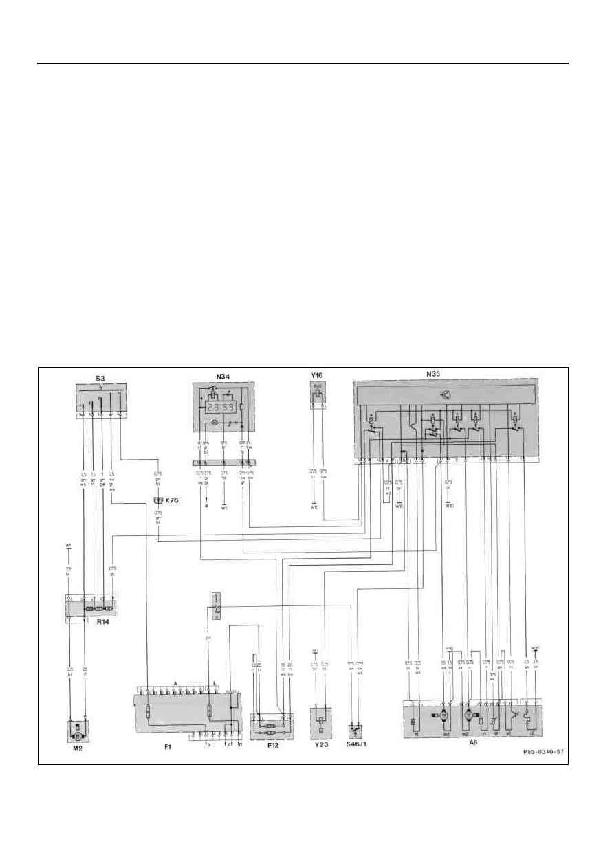
Wiring diagram, auxiliary heater, model 201
A6
Auxiliary heater unit
N34
Auxiliary heater timer
A6b1
Temperature sensor
R14
Blower motor preresistor group
A6f1
Temperature cutout
S3
Air volume switch
A6m1
Circulating pump
Copyright Daimler AG 02.12.14 G/08/07. Ten wydruk WIS nie jest obj
ę
ty funkcj
ą
aktualizacji.
strona 1

A6m1
Circulating pump
S46/1
Auxiliary heater microswitch
A6m2
Combustion air blower
W1
Main ground (behind instrument cluster)
A6r1
Combustion air blower preresistor
W10
Battery ground
A6r2
Glow plug
X5/1
Interior terminal block
A6v1
Flame monitor, photoelectric cell
X76
Air volume switch/auxiliary heater
F1
Electrical center
connection
F12
Auxiliary heater auxiliary fuse box
Y16
Auxiliary heater switchover valve
M2
Blower motor
Y23
Auxiliary heater fuel metering pump
N33
Auxiliary heater control unit
a
To terminal block X6 terminal 58d
a
Blower control relay
b
To ignition starter switch terminal 15X
b
Circulating pump relay
c
To ignition starter switch terminal 30
c
Combustion air blower/full-load relay
d
To ignition starter switch terminal 15
d
Combustion air blower/part-load relay
* *
Ground cable only on cars with diesel
e
Glow plug relay
engine
Copyright Daimler AG 02.12.14 G/08/07. Ten wydruk WIS nie jest obj
ę
ty funkcj
ą
aktualizacji.
strona 2

Starting by switching on with timer (N34)
Part-load switching (approx. half heating
and subsequent full-load operation (full
capacity)
heating capacity)
When a coolant temperature of approx. 80°C
If the contact in the timer (N34) is closed,
is reached in the auxiliary heater heating
terminal 5 of connector A of the control unit
unit (A6), the temperature sensor (A6b1)
(N33) and the switchover valve (Y16) are
signals this to the control unit (N33) as a
energized. The electronics in the control unit
result of its altered resistance, the
(N33) allow a safety switching time of 120 s
electronics of which open the relay (N33c)
to commence. Simultaneously, electronics in
and in turn close the relay (N33d). The
the control unit (N33) close the relay (N33e)
combustion air blower (A6m2) on the
for the glow plug (A6r2) and relay (N33b) for
auxiliary heater heating unit (A6) is now
the circulation pump (A6m1 or A31m1 or
energized via the resistor (A6r1) on the
M13/2); both are operating. The fuel
auxiliary heater heating unit (A6). As a
metering pump (Y23) is also energized
result, the combustion air blower (A6m2)
approx. 30 s later by the electronics in the
only runs at approx. half-speed.
control unit (N33). The voltage is clocked by
At the same time the electronics in the
the electronics in the control unit (N33).
control unit (N33) halve the number of
35 s after switching on, the electronics in the
cycles of the fuel metering pump (Y23) and
control unit (N33) close the relay (N33c),
thus adapt the fuel supply to the lower
which energizes the combustion air blower
demand.
(A6m2) on the auxiliary heater heating unit
Start of combustion interval
(A6).
Once a coolant temperature of approx. 85°C
has been reached in the auxiliary heater
Combustion now commences. The flame
heating unit (A6) the temperature sensor
monitor (A6v1) in the auxiliary heater
heating unit (A6) signals the stabilization of
(A6b1) signals this to the control unit (N33)
combustion to the control unit (N33). The
as a result of its altered resistance.
electronics in the control unit (N33) open the
relay (N33e) and switch off the glow plug
The electronics in the control unit (N33)
(A6r2). The auxiliary heater is now
switch off the fuel metering pump (Y23) and
operating.
switch over from relay (N33d) to relay
Switching on the heater blower
(N33c) so that the combustion air blower
Once the coolant temperature in the
(A6m2) runs at a higher speed.
auxiliary heater heating unit (A6) has risen
After 60 s (after-running) the relay (N33c)
to approx. 55°C, the temperature sensor
opens and thus switches off the combustion
(A6b1) signals this to the control unit (N33)
air blower (A6m2). Circulation pump (A6m1
as a result of its altered resistance. The
or A31m1 or M13/2) and heater blower (M2)
electronics in the control unit (N33) close the
continue running.
relay (N33a) and thus energize the blower
motor (M2).
Copyright Daimler AG 02.12.14 G/08/07. Ten wydruk WIS nie jest obj
ę
ty funkcj
ą
aktualizacji.
strona 3

End of combustion interval
Switching off with timer in controlled
Once the coolant temperature in the
mode with after-running completed
auxiliary heater heating unit (A6) has
The circulation pump (A6m1 or A31m1 or
dropped to approx. 80°C, the temperature
M13/2) and the blower motor (M2) are
sensor (A6b1) signals this to the control unit
operating.
(N33) as result of its altered resistance, the
By switching off with the timer (N34), the
electronics of which close the relay (N33e)
power to terminal 5 of connector A at the
for the glow plug (A6r2) and start up the fuel
control unit (N33) and to the switchover
metering pump (Y23) 30 s later. The relay
valve (Y16) is interrupted. The electronics in
the control unit (N33) open the relay (N33b)
(N33c) for the combustion air blower (A6m2)
for the circulation pump (A6m2 or A31m1 or
is also closed 35 s after the relay (N33e) by
M13/2) and the relay (N33a) for the blower
motor (M2) and in this way switch them off.
the electronics in the control unit (N33).
At the same time, the operating indicator
Combustion is started. Once combustion has
lamp goes out.
stabilized, this is signalled by the flame
monitor (A6v1) to the control unit (N33). The
electronics in the control unit (N33) open the
relay (N33e) and thus switch off the glow
plug (A6r2). Once a coolant temperature of
approx. 80°C has been reached, the
temperature sensor (A6b1) signals this to
the control unit (N33) and the system
switches to part-load.
Full-load switching (full heating capacity)
Switching is performed automatically when,
because of low outside temperatures, part-
load (approx. half heating capacity) is not
sufficient to maintain the coolant
temperature above 70°C. Once the coolant
temperature has dropped to approx. 70°C in
the auxiliary heater heating unit (A6), the
temperature sensor (A6b1) signals this to
the control unit (N33) by its altered
resistance. The electronics in the control unit
(N33) open the relay (N33d) and in turn
Copyright Daimler AG 02.12.14 G/08/07. Ten wydruk WIS nie jest obj
ę
ty funkcj
ą
aktualizacji.
strona 4

Switching off at full-load or part-load with
Automatic cutout in the event of a fault in
the timer
controlled mode
When switching off from full or part-load with
If a fault occurs during the controlled mode,
the timer (N34), the power to terminal 5 of
e.g. the temperature cutout (A6f1) is
connector A of the control unit (N33) and to
activated, combustion is interrupted. If the
the switchover valve (Y16) is interrupted.
coolant temperature in the auxiliary heater
The electronics in the control unit (N33)
heating unit (A6) then drops to approx. 80°C,
switch off the fuel metering pump (Y23) and
two start attempts are made, followed by a
combustion ceases. At the same time, the
fault cutout because no combustion has
relay (N33a) opens and the blower motor
taken place. The operating indicator lamp
(M2) is switched off. 60 s later (after-
(green) goes out.
running), the electronics in the control unit
Automatic cutout in the event of a fault in
(N33) open the relay (N33b) for the
part-load or full-load operation
circulation pump (A6m1 or A31m1 or M13/2)
If the temperature cutout (A6f1) is activated
and the relay (N33c) for the combustion air
during part-load or full-load operation, the
blower (A6m2). Circulation pump (A6m1 or
power for the metering pump (Y23) is
A31m1 or M13/2) and combustion air blower
interrupted and the flame goes out. The
(A6m2) are switched off. The operating
flame monitor (A6v1) signals to the control
indicator lamp (green) goes out. During
unit (N33) that the flame has been
after-running at part-load, the electronics in
extinguished. The electronics in the control
the control unit (N33) switch from relay
unit (N33) open the relay (N33a) and the
(N33d) to relay (N33c) so that the
blower motor (M2) is switched off.
combustion air blower (A6m2) runs at high
60 s later (after-running), the electronics
speed.
(N33) open the relay (N33b) for the
Automatic cutout in the event of
circulation pump (A6m1 or A31m1 or M13/2)
unsuccessful combustion
and the relay (N33c) for the combustion air
If no combustion occurs during the safety
blower (A6m2), and both are switched off.
switching period of 120 s after switching on
The operating indicator lamp goes out. For
the heater, the electronics in the control unit
after-running at part-load, a switchover is
(N33) immediately perform an automatic
made from relay (N33d) to relay (N33c) so
repeat start.
that the combustion air blower (A6m2) is
If during the new safety switching time of
running at high speed.
120 s combustion still does not occur, the
electronics in the control unit (N33) switch
off the fuel metering pump (Y23) and 60 s
later (after-running) open the relay (N33b)
Copyright Daimler AG 02.12.14 G/08/07. Ten wydruk WIS nie jest obj
ę
ty funkcj
ą
aktualizacji.
strona 5
Wyszukiwarka
Podobne podstrony:
0400 Function description D Electrical function, control unit (Webasto no 105 499) Auxiliary heater
0400 Function description B Operating principle with function diagram Auxiliary heater Models 124,
0400 Function description auxiliary heater A General Models 124, 126, 201
0410 Function test Auxiliary heating BBW DBW 46 Models 124, 126, 201
0622 Removal and installation of control unit for airbag seat belt tensioner Model 126 (from 09 87)
0620 Removal and installation of control unit for airbag seat belt tensioner Model 126 (to 08 87)
0402 Arrangement of components Auxiliary heater A Model 124
Wack, Tantleff Dunn Relationship between Electronic Game Playing, Obesity and Psychological Functio
Attitudes toward Affirmative Action as a Function of Racial ,,,
Changes in Brain Function of Depressed Subjects During
Detection and Function of Opioid Receptors on Cells from the Immune System
Functions of the Nervous System
więcej podobnych podstron