83-400
Function description
A. General
The auxiliary heater is connected to the
The auxiliary heater must not be operated in
coolant circuit of the engine. It can be
enclosed areas with no exhaust extraction
switched on when the car is parked or when
facility, even with the programmed heating
driving if a higher heating capacity is
mode. The auxiliary heater should be
required.
switched off at filling stations.
The auxiliary heater is designed to heat the
If the power for the timer is interrupted for
passenger compartment and to defrost the
more than 3 s, the time display flashes when
car windows. The cold engine is also
one of the buttons 1 - 3 has been pressed.
preheated by means of the coolant which
The time should then be reset.
assures more reliable starting of the engine
even at low outside temperatures.
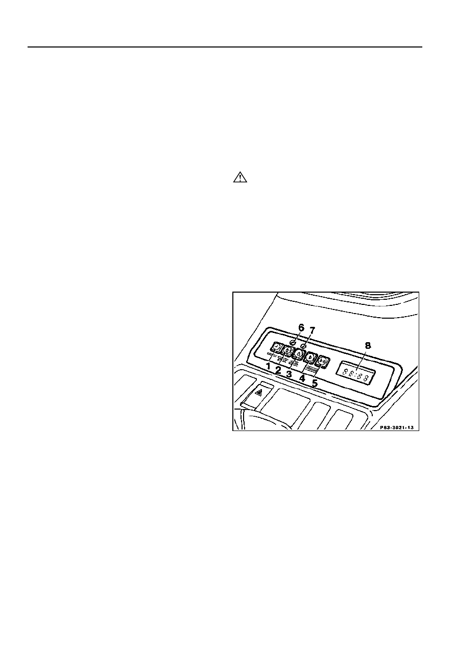
Timer (1st version, model 201.02 up to
approx. 03/85)
The auxiliary heater is switched on and off
with the timer. This is installed in the center
console. The heater starting point can be
preselected up to 24 hours in advance.
1
Pushbutton for calling up current time display
2
Pushbutton for programmed heating
3
Pushbutton for instant heating
4
Pushbutton for slow setting of clock time
5
Pushbutton for rapid setting of clock time
6
Programmed heating indicator lamp (yellow)
7
Operating indicator lamp (green)
8
Clock time display
Copyright Daimler AG 02.12.14 G/08/07. Ten wydruk WIS nie jest obj
ę
ty funkcj
ą
aktualizacji.
strona 1
Instant heating operation
Press pushbutton (3). The auxiliary heater
switches on and the green operating indicator
lamp (7) comes on. In the instant heating
mode, the automatic operating time of max.
59 minutes is indicated in the display (8). The
automatic operating time can be reduced by
pressing pushbuttons 4 and 5.
The auxiliary heater can be switched off with
pushbutton (3) before the expiry of the
automatic operating time.
When the instant heating mode is switched
off/on (pushbutton 3) during the maximum
operating time of 59 minutes, the remaining
operating time is indicated in the display (8)
each time the heater is switched on, always
rounded up or down to 9 minutes, i.e. the
display shows 9, 19, 29 minutes, etc. If the
full operating time (59 minutes) is desired
instead of the remaining time displayed, e.g.
29 minutes, the time in the display (8) must
be set to 00. This switches off the auxiliary
heater. It is then necessary to press
pushbutton (3) (on). The operating time is
now 59 minutes.
Operation with programmed heating
Press pushbutton (2), the yellow programmed
heating indicator lamp (6) comes on. The
heater is switched on automatically at the
selected time and the green operating
indicator lamp (7) also comes on. Automatic
operating time 1 hour.
Copyright Daimler AG 02.12.14 G/08/07. Ten wydruk WIS nie jest obj
ę
ty funkcj
ą
aktualizacji.
strona 2
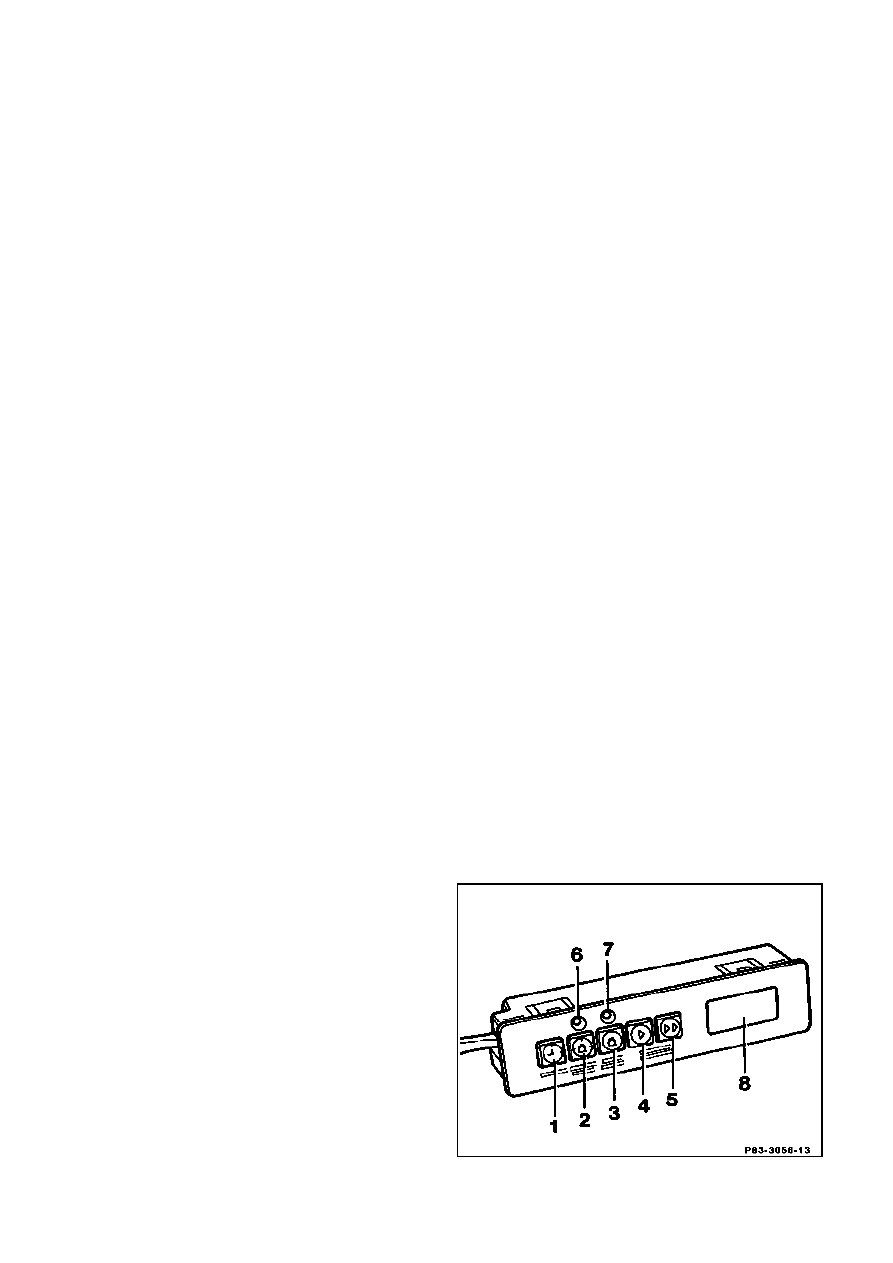
1
Pushbutton for calling up current time display
2
Pushbutton for switching on/off programmed
heating
3
Pushbutton for switching on/off instant heating
4
Pushbutton for slow setting of clock time
5
Pushbutton for rapid setting of clock time
6
Programmed heating indicator lamp (yellow)
7
Operating indicator lamp (green)
8
Clock time display
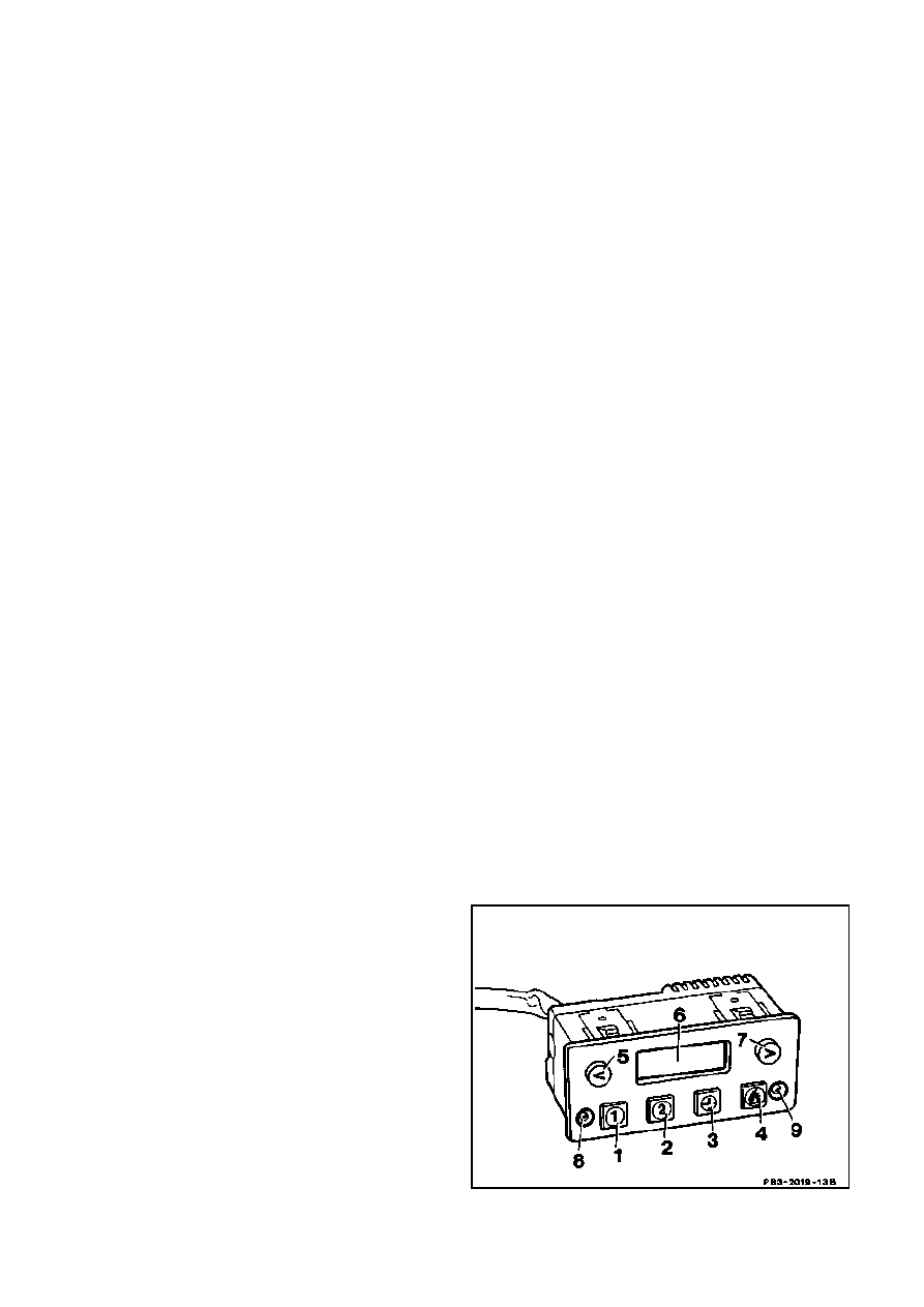
Timer (2nd version, model 201.02 as of
approx. 04/85)
Revised functions
a) Forward and reverse (buttons 5 and 7)
for setting time of day and cut-in time.
b) The automatic operating time for instant
heating (button 4) is not displayed. It is 1
hour.
c) One cut-in time can be stored for
programmed heating with each of buttons (1)
and (2). If the programmed heating mode is
switched on with button 1 or 2, the yellow
programmed heating indicator lamp (8)
comes on. The number of the button pressed
appears in the display (8) and the cut-in time
for 20 seconds. Once the auxiliary heater is
operating, only the green operating indicator
lamp (9) is illuminated.
1/2 Pushbutton for programmed heating
3
Pushbutton for displaying current time
4
Pushbutton for instant heating
5
Pushbutton for reverse setting of time of day and
cut-in time
6
Time display
7
Pushbutton for forward setting of time of day and
cut-in time
8
Yellow programmed heating indicator lamp
9
Green operating indicator lamp
Copyright Daimler AG 02.12.14 G/08/07. Ten wydruk WIS nie jest obj
ę
ty funkcj
ą
aktualizacji.
strona 3
Control unit
The control unit (N33) houses relays and
time switches which automatically control the
operating sequence in combination with the
temperature sensor of the auxiliary heater
heating unit (A6).
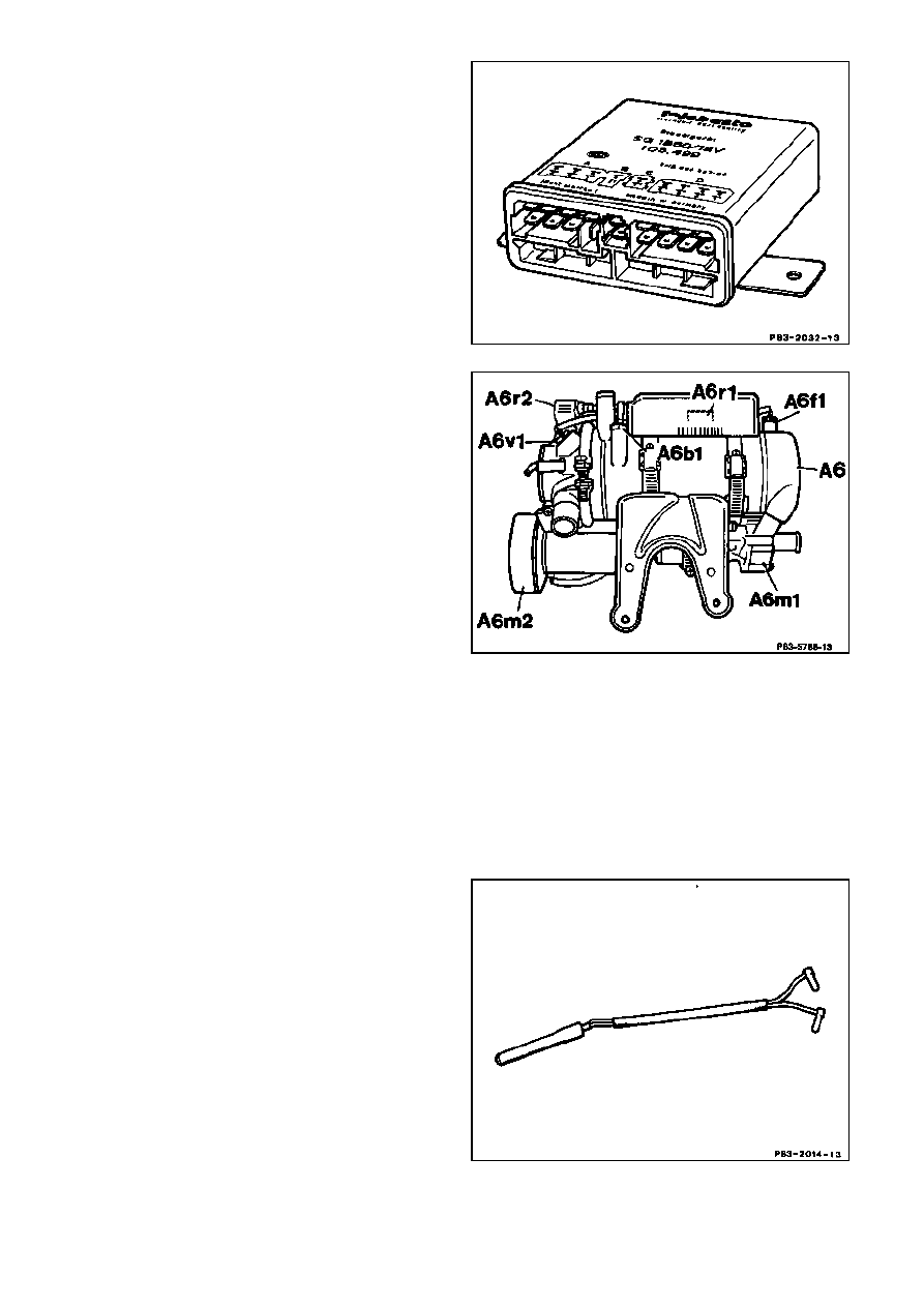
Heater
The fuel-air mixture is burnt in the heater and
thus heats the coolant in the water jacket.
The components listed in the illustration are
part of the heater assembly and perform the
functions described below.
A6
Auxiliary heater unit
A6b1
Temperature sensor
A6f1
Temperature cutout
A6m1
Circulating pump
A6r1
Combustion air blower preresistor
A6m2
Combustion air blower
A6r2
Glow plug
A6v1
Flame monitor
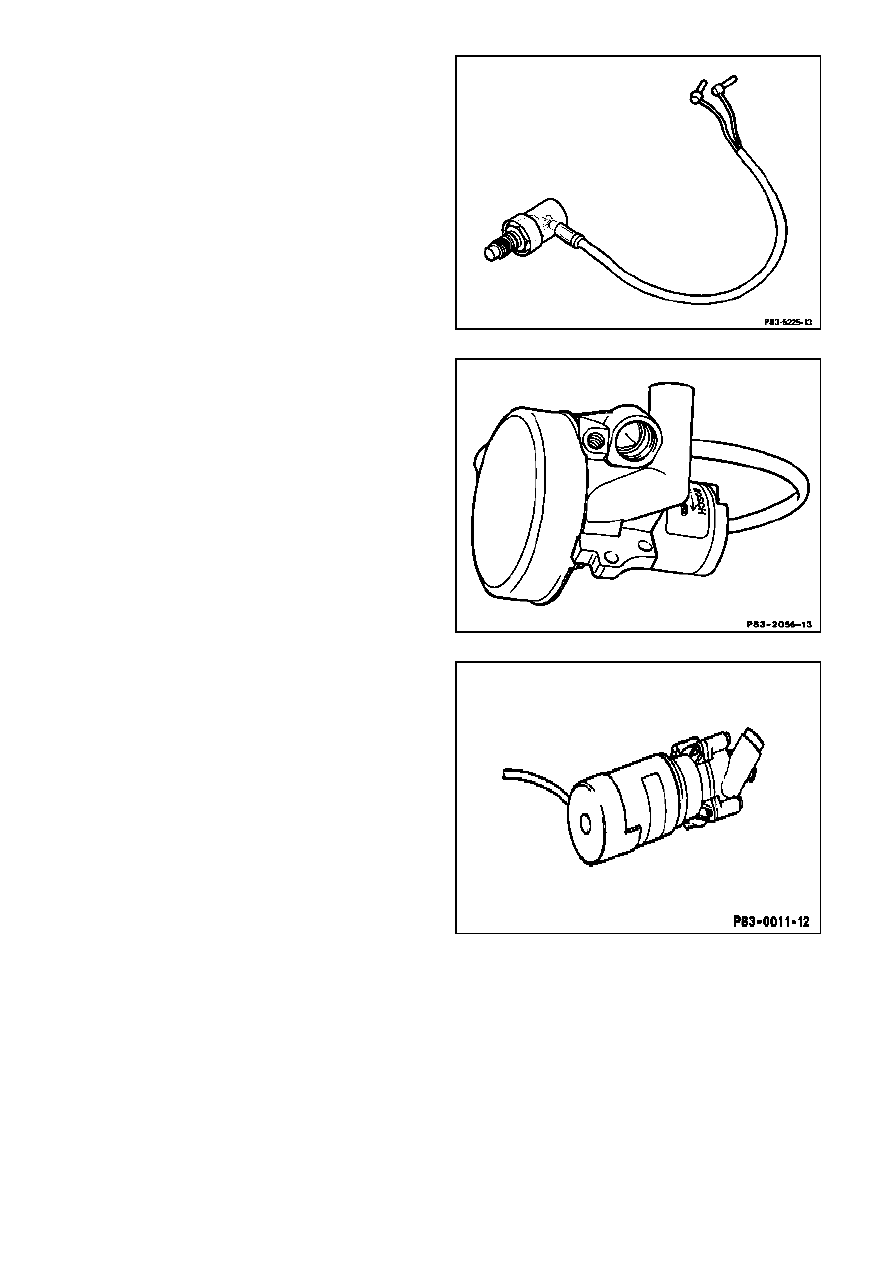
Flame monitor (in heater)
The flame monitor is a light-sensitive
component which monitors combustion. If
combustion stops, the flame monitor signals
this to the control unit and the control unit
switches off the heater (malfunction).
Copyright Daimler AG 02.12.14 G/08/07. Ten wydruk WIS nie jest obj
ę
ty funkcj
ą
aktualizacji.
strona 4
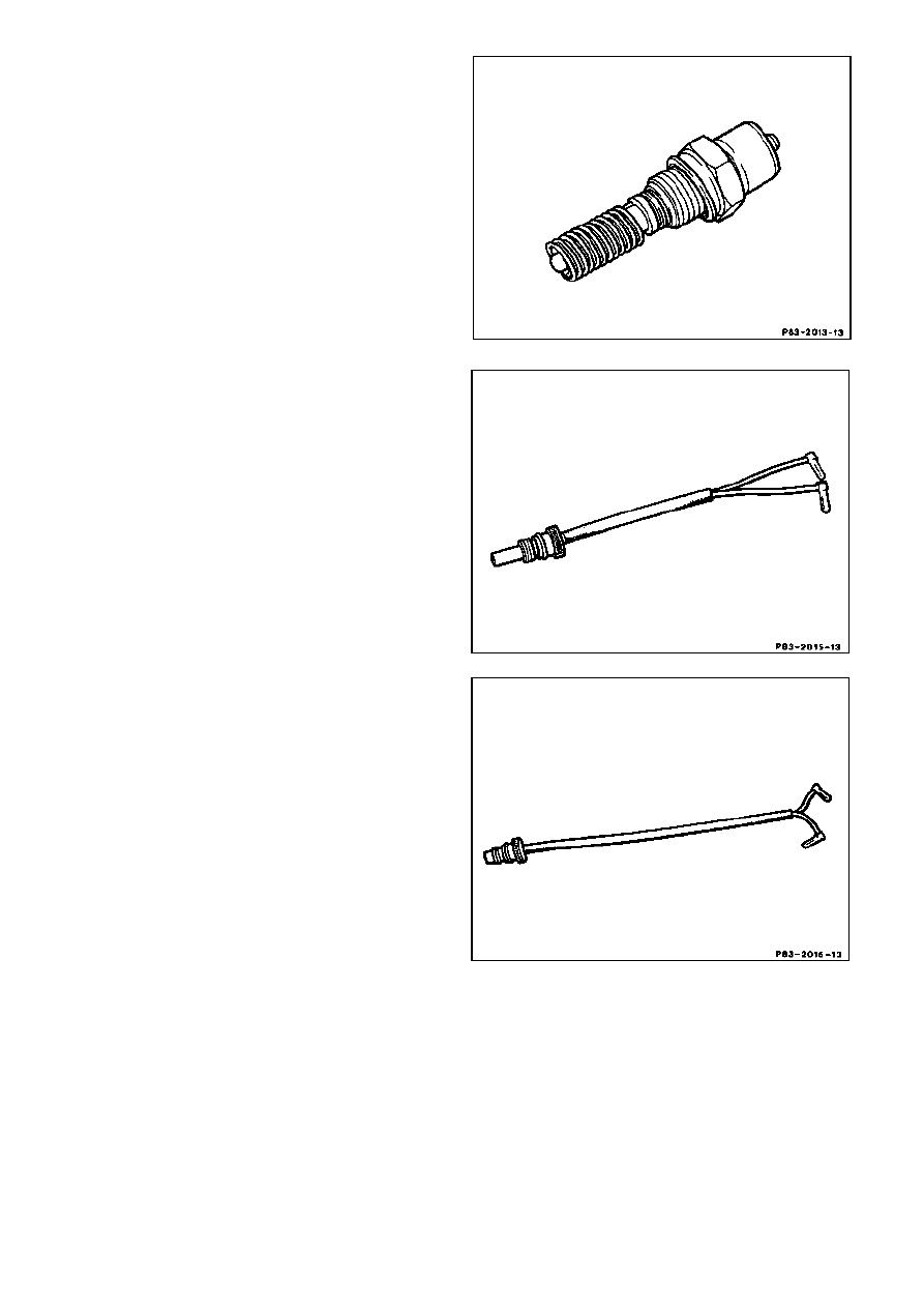
Glow plug (in heater)
The glow plug produces the heat necessary
for starting and is switched off by the flame
monitor via the control unit (N33) after
combustion has stabilized.
Temperature sensor (in heater)
The temperature sensor is a resistor (PTC)
which alters its value in response to
temperature. Its resistance increases as
temperature increases. Switching on the
heater blower and operation of the heater
(full or half heating capacity or combustion
interval) is controlled by the temperature
sensor via the control unit (N33).
Temperature cutout (in heater)
1st version
The temperature cutout is an overheating
protection. At a temperature > 140°C, the
fuse in the temperature cutout blows,
interrupting the power for the fuel metering
pump. This results in full shutdown of the
heater.
Copyright Daimler AG 02.12.14 G/08/07. Ten wydruk WIS nie jest obj
ę
ty funkcj
ą
aktualizacji.
strona 5
Resettable temperature cutout (in heater)
2nd version
The temperature cutout is an overheating
protection. At a coolant temperature > 117°C,
the resettable temperature cutout is
activated, interrupting the power for the fuel
metering pump. This results in fault shutdown
of the heater.
Combustion air blower (on heater)
The combustion air blower delivers the
quantity of air required for mixture
preparation. Control is by means of the
temperature sensor via the control unit (N33).
Circulation pump (on heater)
The circulation pump ensures coolant
circulation. It operates when the auxiliary
heater is switched on, and on models
124.061, 124.0 up to approx. 09/92, (except
model 124.034), models
124.120/128/133/188/193/3 up to approx.
01/93, models
124.125/127/130/180/185/190/2, models
126.02 and 201 even when the ignition is
switched on if the vehicle heating is in
heating mode.
Copyright Daimler AG 02.12.14 G/08/07. Ten wydruk WIS nie jest obj
ę
ty funkcj
ą
aktualizacji.
strona 6
Circulation pump - models 124.034/036
The circulation pump ensures coolant
circulation. It operates when the auxiliary
heater is switched on.
Model 124.034
Model 124.036
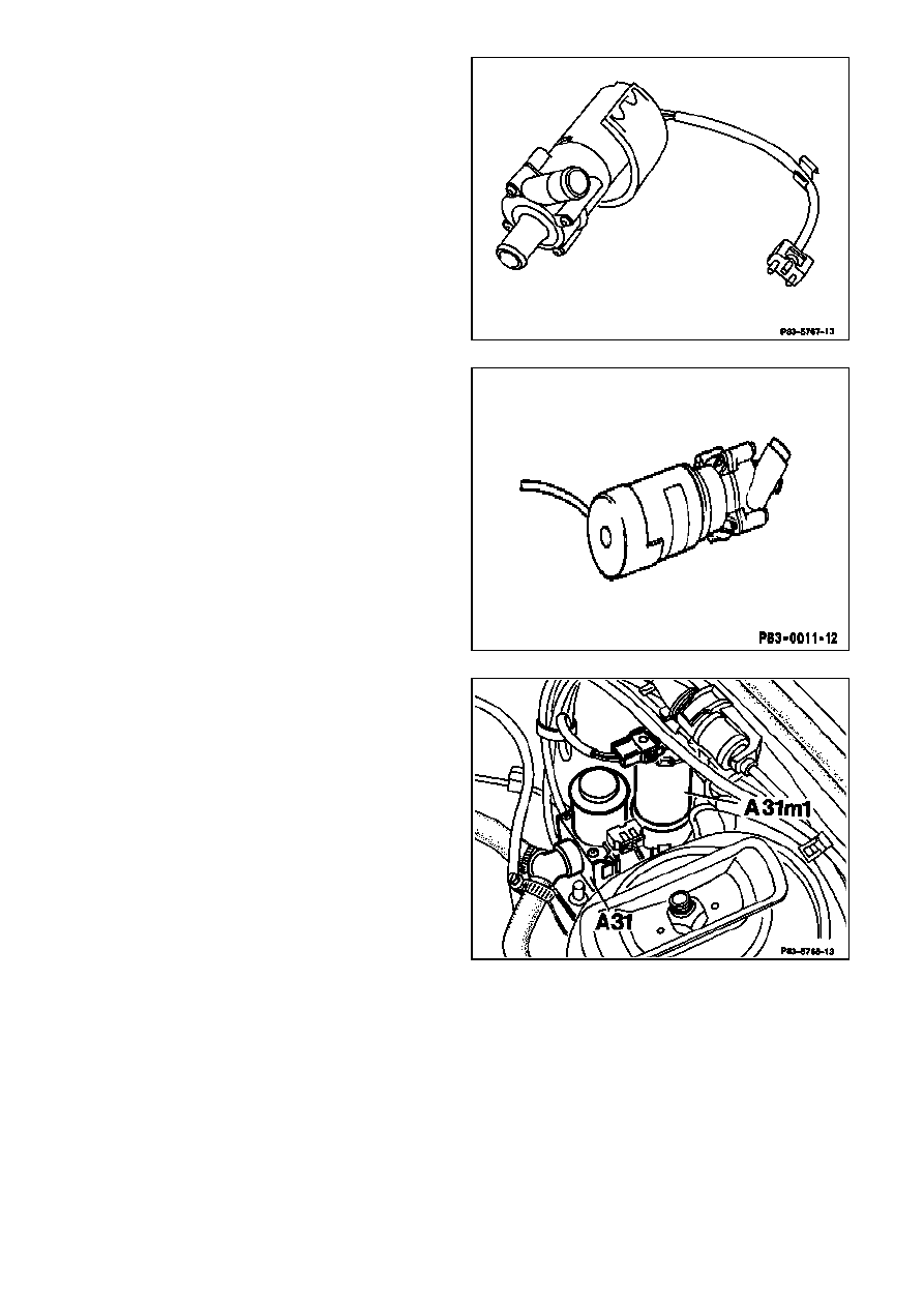
Heating system supply unit (A31)
Model 124.0 as of approx. 10/92 (excluding
models 124.034/036/061),
models 124.120/128/133/188/193/3 as of
approx. 02/93, models 124.126/131/186/191
No circulation pump is fitted to the auxiliary
heater heating unit (A6). The coolant is
circulated by actuating the production
circulation pump (A31m1) which is integrated
in the heating system supply unit (A31).
Copyright Daimler AG 02.12.14 G/08/07. Ten wydruk WIS nie jest obj
ę
ty funkcj
ą
aktualizacji.
strona 7
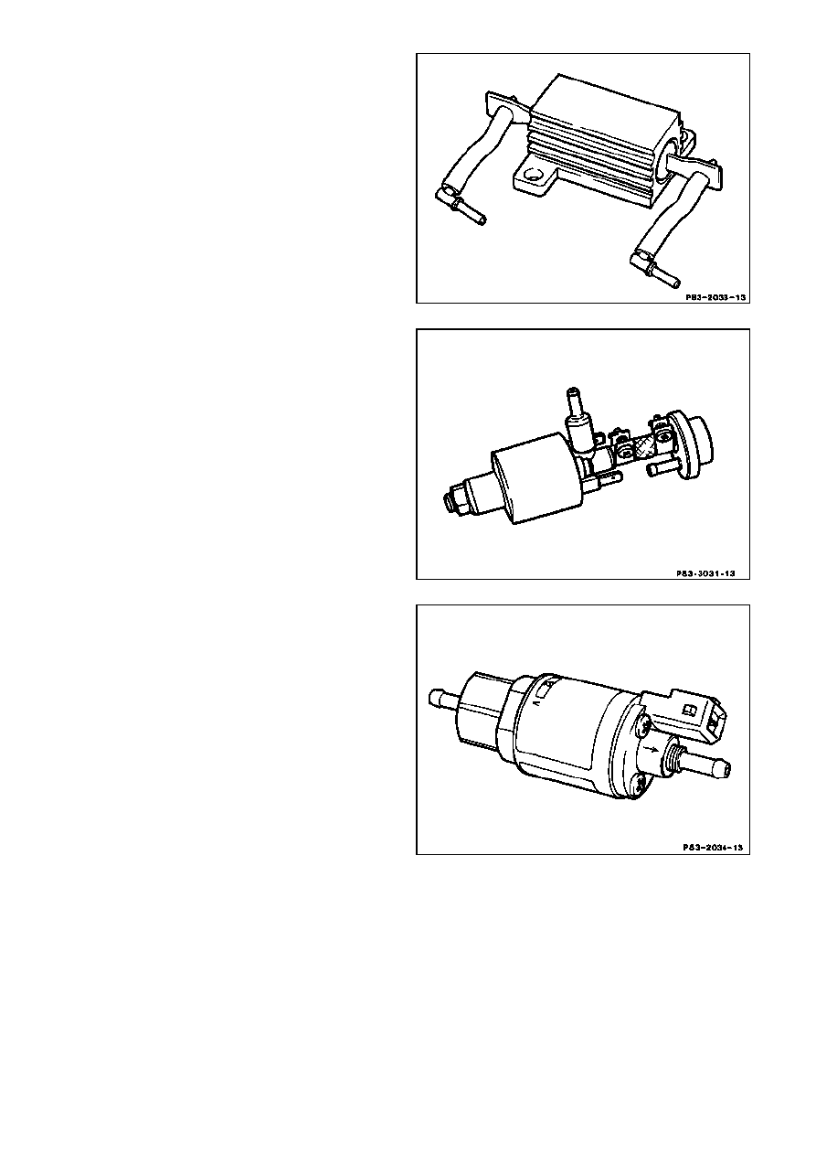
Resistor on the heater
At partial load operation, the resistor of the
control unit (N33) is connected upstream of
the combustion air blower so that the
combustion air blower operates only at
approx. half speed.
Fuel metering pump (1st version for
model 124 up to approx. 08/89, on model
201 up to approx. 08/88)
The fuel metering pump delivers the quantity
of fuel necessary for combustion from the
fuel tank to the heater. The pump is
controlled by the control unit (N33).
Fuel metering pump (2nd version on
model 124 as of approx. 09/89, on model
201 as of approx. 09/88)
The function of the fuel metering pump is
identical to the 1st version. The operating
range for fuel induction has been increased,
enabling the pressure reducer on diesel
models to be deleted.
Copyright Daimler AG 02.12.14 G/08/07. Ten wydruk WIS nie jest obj
ę
ty funkcj
ą
aktualizacji.
strona 8
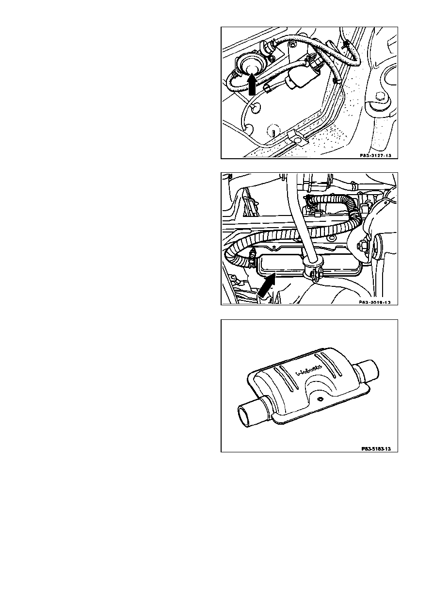
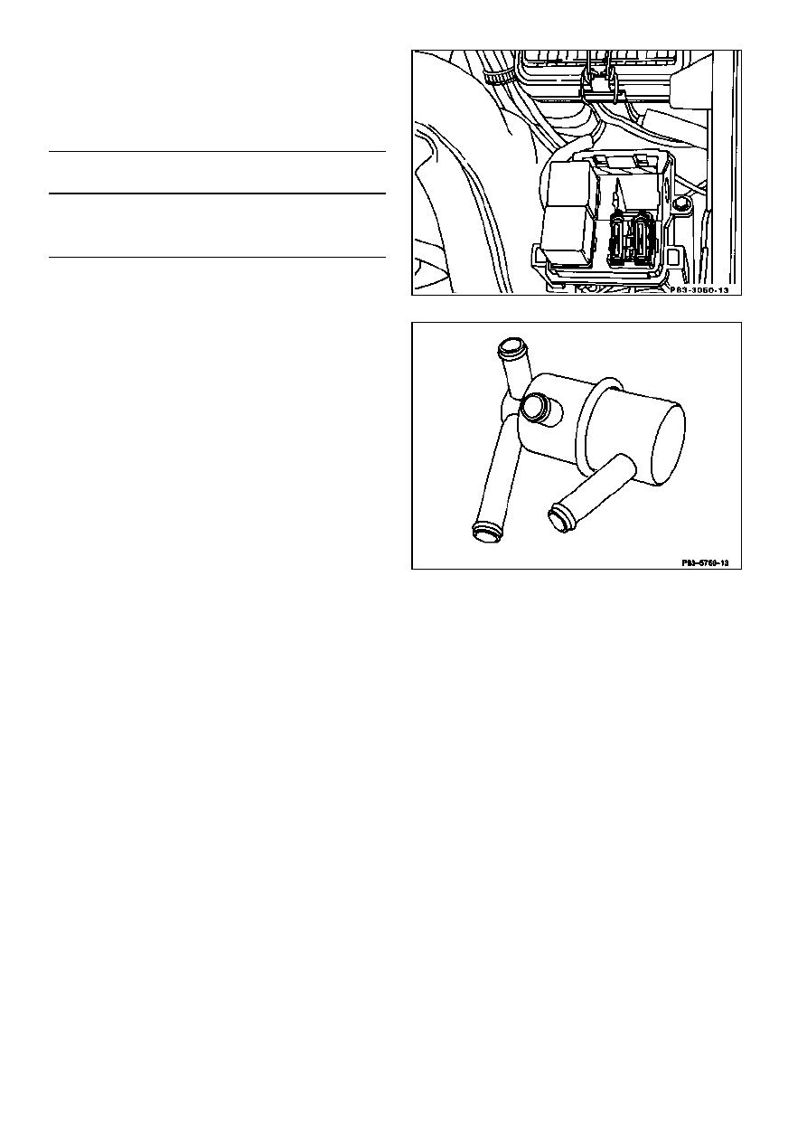
Pressure reducer
The pressure reducer (arrow) on diesel
models is connected upstream of the fuel
metering pump (1st version), as the pressure
at the fuel extraction point is too high.
Exhaust silencer (1st version)
The exhaust silencer (arrow) muffles the
combustion noise and vents the exhaust gas
into the atmosphere.
Exhaust silencer (2nd version)
Copyright Daimler AG 02.12.14 G/08/07. Ten wydruk WIS nie jest obj
ę
ty funkcj
ą
aktualizacji.
strona 9
Electrical fuses
The auxiliary heater is protected against
overload and short-circuit with two fuses.
Glow plug
Auxiliary heater control
Fuse
Fuse
16 amps
8 amps
Thermostat
Models 124.034/036
The thermostat has three functions in
conjunction with the auxiliary heater coolant
circuit.
Up to approx. 55°C coolant temperature, the
coolant supply from the engine to the
auxiliary heater heating unit (A6) is shut off
and the coolant in the engine does not heat
up.
Between 55°C and 65°C coolant
temperature, the thermostat starts to open
and regulates the coolant supply from the
engine to the auxiliary heater heating unit
(A6). Thus the coolant in the engine is also
heated up.
Above 65°C coolant temperature in the
engine, the thermostat is fully open and the
coolant is still only supplied to the auxiliary
heater heating unit (A6) from the engine.
The engine is therefore fully incorporated into
the coolant circuit.
Copyright Daimler AG 02.12.14 G/08/07. Ten wydruk WIS nie jest obj
ę
ty funkcj
ą
aktualizacji.
strona 10
Wyszukiwarka
Podobne podstrony:
Programmed repair Auxiliary heater Part C Models 124, 126 020 024 025
Programmed repair Auxiliary heater Part C Models 124, 126 020 024 025
0400 Function description B Operating principle with function diagram Auxiliary heater Models 124,
0400 Function description D Electrical function, control unit (Webasto no 105 499) Auxiliary heater
0400 Function description electrical function of control unit Auxiliary heater Models 124, 126, 201
0410 Function test Auxiliary heating BBW DBW 46 Models 124, 126, 201
0409 Troubleshooting information Models 124, 126, 201 with auxiliary heating BBW DBW 46
0403 Coolant circuit with diagram Auxiliary heater A Models 124 061,124 0 to approx 09 92 (except
0402 Arrangement of components Auxiliary heater A Model 124
fdl function description langua Nieznany
BizAgi Functional Description
Volkswagen Golf Variant 2007, Golf Variant 2010, Jetta 2005 Auxiliary heater Edition 03 2010 Work
DESCRIPTION FOR THE GENERAL PUBLIC
więcej podobnych podstron