
Uppgjord - Prepared
Dokansv/Godkänd - Doc respons/Approved
Faktaansvarig - Subject responsible
Kontr - Checked
Nr - No.
Datum - Date
File
Rev
WORK INSTRUCTION
1 (00)
ETX/TX/DZ MYON
2/000 21-FCK 114 20 Uen
ETX/TX/DT (H. Westlund)
1996-01-01
D
FDL – FUNCTION DESCRIPTION LANGUAGE
Contents
Page
1
REVISION INFORMATION
..................................................
3
2
INTRODUCTION
....................................................................
3
3
LANGUAGE DESCRIPTION
................................................
3
3.1
Overview
..................................................................................
3
3.2
The State Transition Model
..................................................
3
3.3
The Event Sequence Model
................................................
4
4
OVERVIEW OF BASIC ELEMENTS
..................................
5
5
STATE-TRANSITION MODEL – SYNTAX AND
SEMANTICS
..........................................................................
10
5.1
Flow
........................................................................................
10
5.2
Transition
................................................................................
11
5.3
Start
........................................................................................
11
5.4
State
........................................................................................
11
5.5
Signal Reception
..................................................................
11
5.6
Signal Sending
......................................................................
11
5.7
Command
..............................................................................
11
5.8
Printout
..................................................................................
11
5.9
Decision and Decision Path Values
..................................
12
5.10
Task
........................................................................................
12
5.11
Macros and Expanded Macros
..........................................
12
5.12
Loop Delimiters
....................................................................
13
5.13
Divergence and Convergence Points
..............................
13
6
STATE-TRANSITION MODEL – SYNTAX TABLE
......
13
7
EVENT-SEQUENCE MODEL – SYNTAX AND
SEMANTICS
..........................................................................
14
7.1
Flow
........................................................................................
14
7.2
Sequence
..............................................................................
14
7.3
Start
........................................................................................
15
7.4
Stop
........................................................................................
15
7.5
Signal Reception
..................................................................
15
7.6
Signal Sending
......................................................................
15
7.7
Command
..............................................................................
15

Uppgjord - Prepared
Dokansv/Godkänd - Doc respons/Approved
Faktaansvarig - Subject responsible
Kontr - Checked
Nr - No.
Datum - Date
File
Rev
WORK INSTRUCTION
2 (00)
2/000 21-FCK 114 20 Uen
1996-01-01
D
7.8
Printout
..................................................................................
15
7.9
Decision and Decision Path Values
..................................
15
7.10
Task
........................................................................................
16
7.11
Macros and expanded Macros
..........................................
16
7.12
Loop Delimiters
....................................................................
16
7.13
Divergence and Convergence Points
..............................
17
8
EVENT-SEQUENCE MODEL - SYNTAX TABLE
.... ....
17
9
MODEL INDEPENDENT ELEMENTS – SYNTAX AND
SEMANTICS
..........................................................................
18
9.1
Flow Lines and Signal Lines
..............................................
18
9.2
Flow Connector
....................................................................
18
9.3
Frame
......................................................................................
19
9.4
Dummy Symbol and Free Text
..........................................
19
10
TEXT ASSOCIATED WITH SYMBOLS
..........................
20
10.1
General
..................................................................................
20
10.2
Star Notation (*)
....................................................................
20
10.3
Hyphen Notation (-)
..............................................................
21
10.4
Identifiers
................................................................................
21
11
DRAWING CONVENTIONS OF FLOW
DESCRIPTIONS
..................................................................
22
12
EXAMPLES
..........................................................................
26
12.1
Some examples using basic Description Elements
... ...
26
12.2
Short Notations
....................................................................
30
12.3
Traffic Functions Outgoing Call
..........................................
32

Uppgjord - Prepared
Dokansv/Godkänd - Doc respons/Approved
Faktaansvarig - Subject responsible
Kontr - Checked
Nr - No.
Datum - Date
File
Rev
WORK INSTRUCTION
3 (00)
2/000 21-FCK 114 20 Uen
1996-01-01
D
1
REVISION INFORMATION
B
Added reference for HLPLEX usage.
C
Trouble report fixed due to redundant phrasing
D
Improved from user feedback
2
INTRODUCTION
This document describes the Ericsson Function Description Language, FDL, which
can be used during Function Design and Function Block Design. To get more infor-
mation on how the language is applied in these activities, it is recommended to also
use the document instructions for Function Description (FD) and Function Block
Description (BD).
The language is based on the CCITT recommendation for the SDL (Specification
and Description Language) graphical language, with modifications that reflect the
ETX traditions concerning the use of flowchart diagrams as well as parts of the re-
sult from the collaboration between ETX, ELLEMTEL and The Swedish Telecom
Administration.
The name FDL has been used as an ETX internal work name for the language in or-
der to indicate the difference compared with the latest CCITT/SDL recommendation.
The language is supported by different tools such as flow chart editors implemented
on PC XT/AT and SUN workstation.
If designing using HLPLEX, see 2/000 21–FCK 114 21 Uen, Flowchart Symbols for
HLPLEX.
3
LANGUAGE DESCRIPTION
3.1
Overview
Interesting aspects of a system are
•
The dynamic behaviour of the system during system operation
•
The static structure of the system.
FDL is a language for describing the dynamic behaviour of a system in the form of
flowchart diagrams containing graphical symbols. FDL can be used for describing
behaviour according to the State-Transition model or according to the
Event-Sequence model. Some of the elements in the language are model dependent.
3.2
The State Transition Model
The dynamic behaviour of a function can be based on the State-Transition model
(also called a ’finite state machine’) including the following concepts:

Uppgjord - Prepared
Dokansv/Godkänd - Doc respons/Approved
Faktaansvarig - Subject responsible
Kontr - Checked
Nr - No.
Datum - Date
File
Rev
WORK INSTRUCTION
4 (00)
2/000 21-FCK 114 20 Uen
1996-01-01
D
•
A function is always in a STATE. Inputs to the function are SIG-
NALS and COMMANDS which are acted upon by the function
depending on its current state. The combination of state and signal/
command received uniquely determines the subsequent actions per-
formed by the function, and the possible next state that the function
may adopt. The changeover from one state to the next state is called
a TRANSITION.
•
The initial state in a transition is called the IN-STATE, and the final
state in a transition in called the NEXT- STATE.
3.3
The Event Sequence Model
The Event-Sequence model is an alternative to the State- Transition model. It de-
fines a way to describe the dynamic behaviour of a function or function block in
terms of event sequences. An event sequence has a defined start-point, which is the
event, followed by a sequence of actions that ends in a defined end-point.
Uppgjord - Prepared
Dokansv/Godkänd - Doc respons/Approved
Faktaansvarig - Subject responsible
Kontr - Checked
Nr - No.
Datum - Date
File
Rev
WORK INSTRUCTION
5 (00)
2/000 21-FCK 114 20 Uen
1996-01-01
D
4
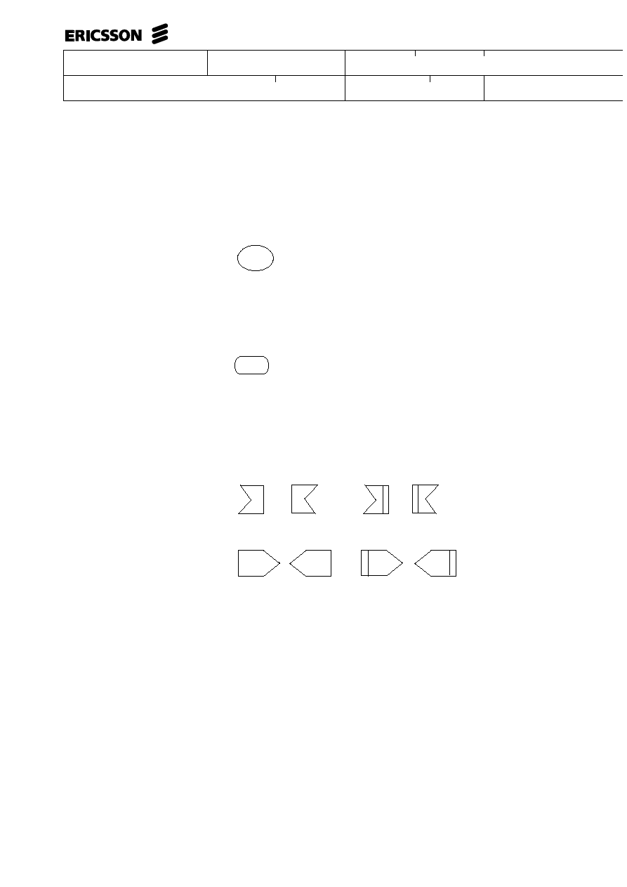
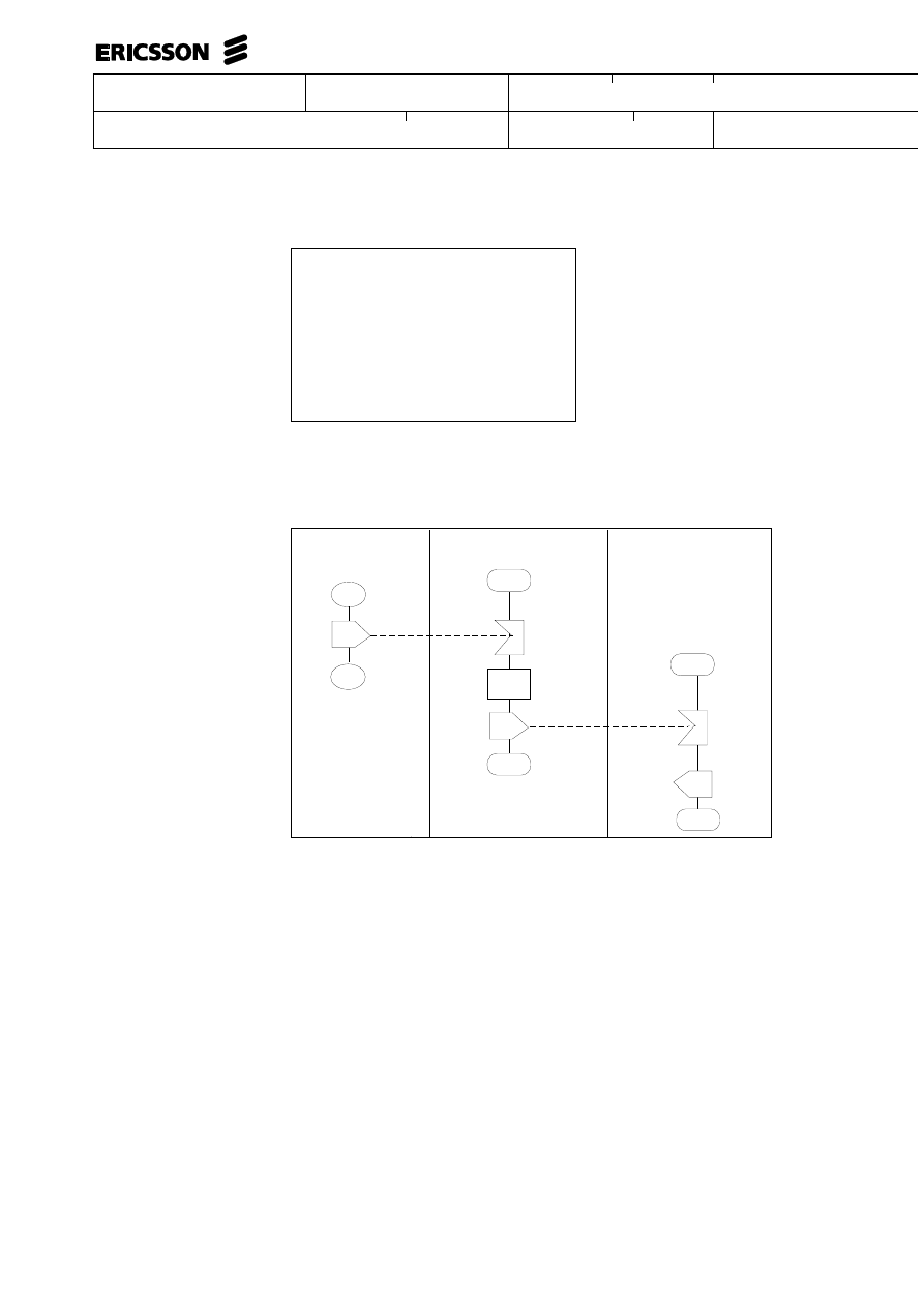
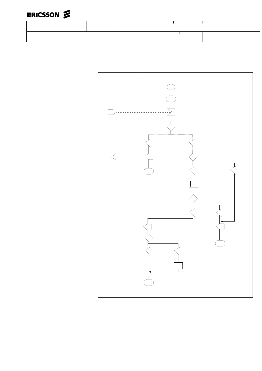
OVERVIEW OF BASIC ELEMENTS
START/STOP symbol
STATE symbol
SIGNAL RECEPETION symbols
SIGNAL SENDING symbols
A START points out the initial start of a flow (state-transition model)
or the start point of an event sequence (event-sequence model).
A STATE is a condition during which a function is ready to accept signals
and commands, and perform transitions accordingly.
This symbol may only be used in state-transition flowcharts.
The symbols with an extra vertical line are internal signals, i.e. signals that
do not participate in the external interaction.
NOTE that the direction of the symbols has no significance.

Uppgjord - Prepared
Dokansv/Godkänd - Doc respons/Approved
Faktaansvarig - Subject responsible
Kontr - Checked
Nr - No.
Datum - Date
File
Rev
WORK INSTRUCTION
6 (00)
2/000 21-FCK 114 20 Uen
1996-01-01
D
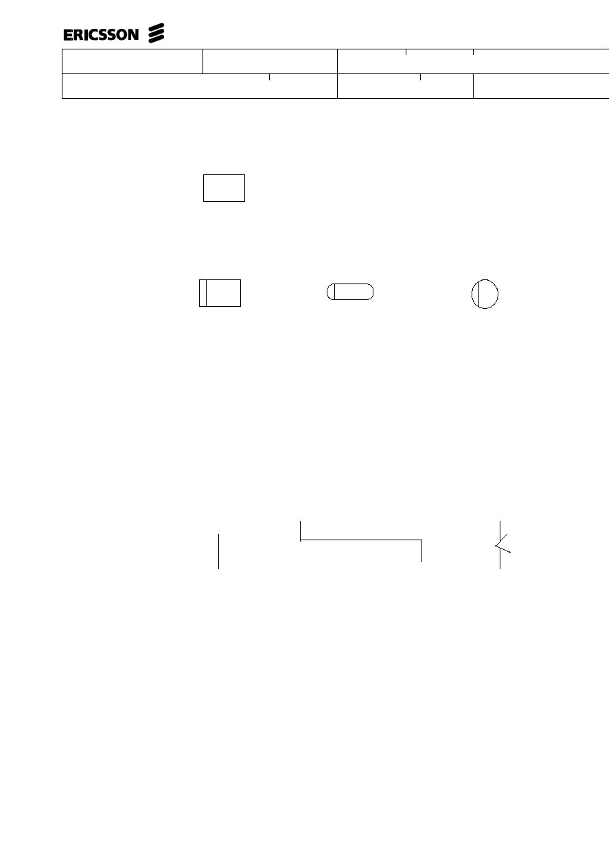
INPUT/OUTPUT symbol
The INPUT/OUTPUT symbol is used to show COMMANDS and PRINTOUTS
COMMAND
xxxxx
PRINTOUT
yyyyy
NOTE
The same symbol is used in SDL to illustrate the SAVE concept, which means that a
signal received by a state is queued and can be received at a subsequent state.
FDL has no element to describe such signal reception mechanisms.
DECISION symbol
DECISION PATH VALUE symbol
A DECISION is the point at which a transition or sequence branches into two or more paths.
Each branch has a specified condition and the flow of control will follow one branch if a
calculation made within the decision corresponds to the value of that condition.
The value of the condition is stated together with the DECISION PATH VALUE
(condition) symbol.
Uppgjord - Prepared
Dokansv/Godkänd - Doc respons/Approved
Faktaansvarig - Subject responsible
Kontr - Checked
Nr - No.
Datum - Date
File
Rev
WORK INSTRUCTION
7 (00)
2/000 21-FCK 114 20 Uen
1996-01-01
D
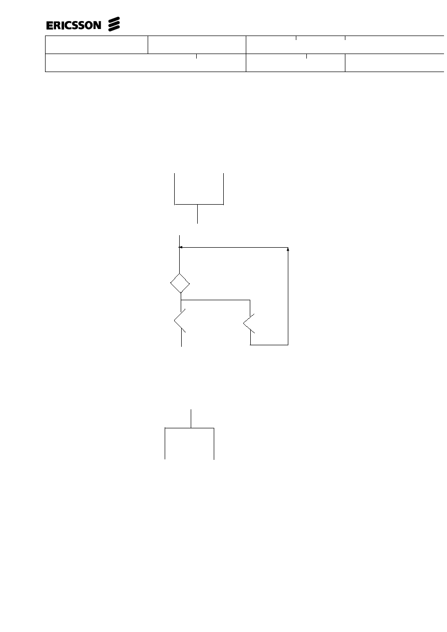
TASK symbol
A TASK represents an action within a transition or sequence.
MACRO CALL symbol
MACRO BEGIN symbol
MACRO END symbol
A macro represents a larger transition or sequence, or a part of a transition or sequence to
be expanded into the flow at one or more points.
The description of the macro definition begins with a MACRO CALL symbol and ends with
one or more MACRO END symbols.
The MACRO CALL symbol indicates where the MACRO is expanded.
MACRO CALL, MACRO BEGIN and MACRO END symbols used to describe the same MACRO
must all be labelled by the same identifier i.e. the name of the macro..
Flow lines are drawn between symbols to describe the flow of execution. Flow lines may be
drawn between any two symbols which may be allowed in a sequence within a flow.
Flow lines that follow a divergence from a DECISION symbol must have a DECISION PATH
VALUE embedded in the flow line.
Flow lines
Uppgjord - Prepared
Dokansv/Godkänd - Doc respons/Approved
Faktaansvarig - Subject responsible
Kontr - Checked
Nr - No.
Datum - Date
File
Rev
WORK INSTRUCTION
8 (00)
2/000 21-FCK 114 20 Uen
1996-01-01
D
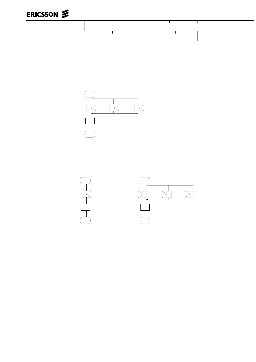
A convergence point is a point where two or more flow lines join together.
Arrows indicate the direction of the horizontal lines in such points in order to
avoid ambiguity.
Convergence point
The arrow will automatically be added by the tool.
The UP-arrow is a symbol
which makes it possible to
draw lines like this.
Divergence point
A divergence point is a point within the execution of a function where one flow line
divides into two or more branches.
Uppgjord - Prepared
Dokansv/Godkänd - Doc respons/Approved
Faktaansvarig - Subject responsible
Kontr - Checked
Nr - No.
Datum - Date
File
Rev
WORK INSTRUCTION
9 (00)
2/000 21-FCK 114 20 Uen
1996-01-01
D
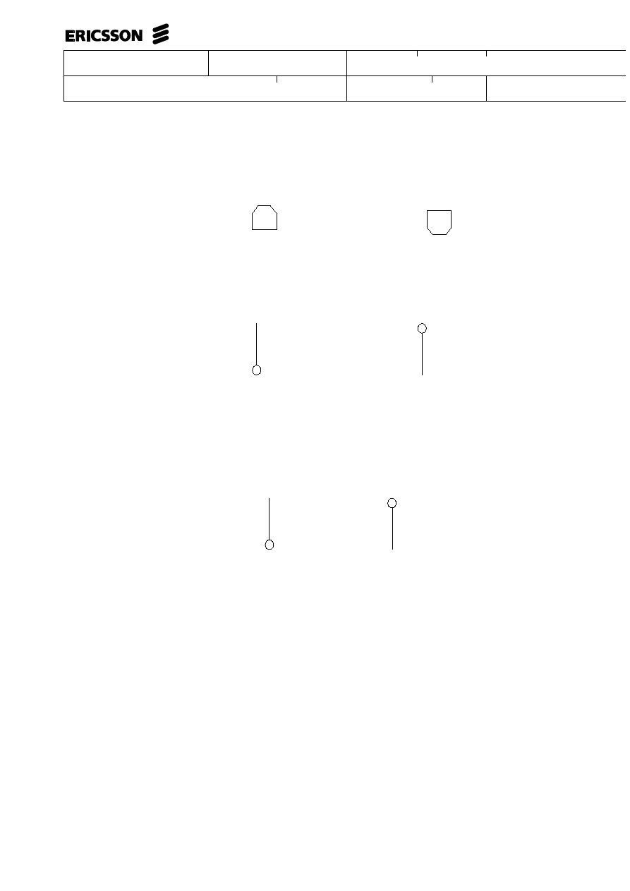
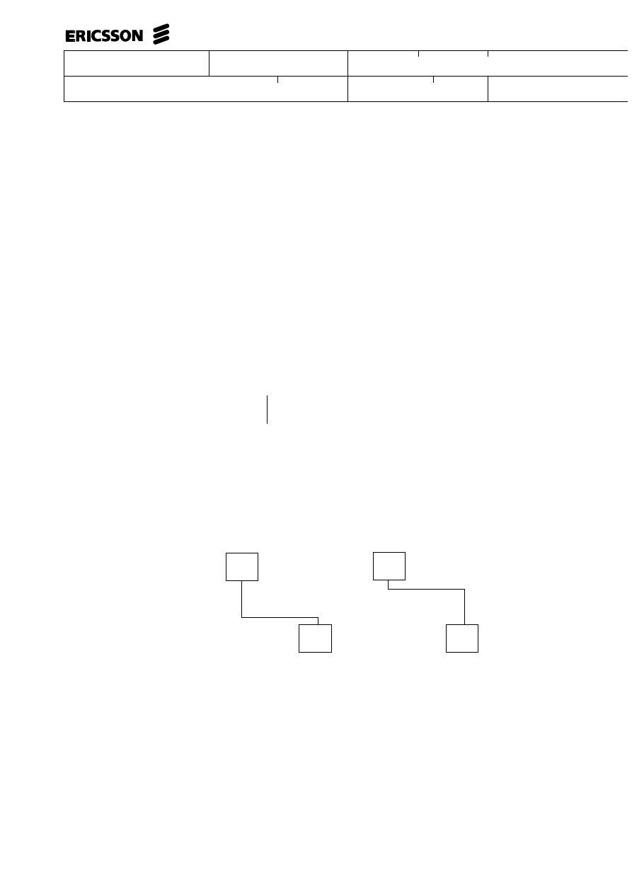
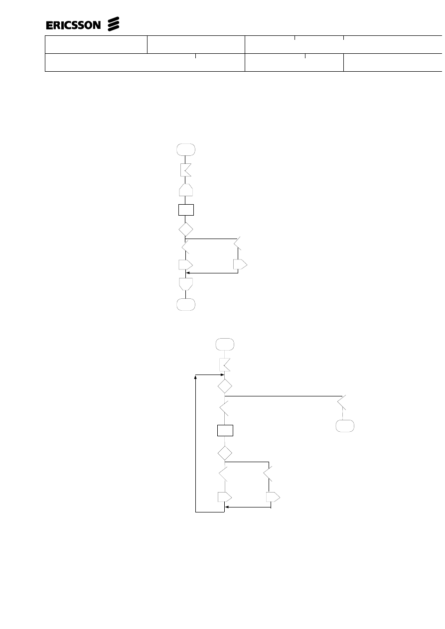
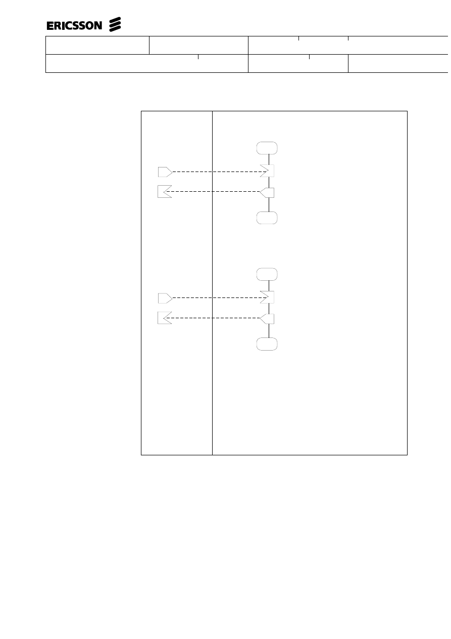
LOOP BEGIN symbol
LOOP END symbol
OUT CONNECTOR symbol
IN CONNECTOR symbol
Connectors are used to divide parts of a flow line which must be divided across
different pages of a document. Connector symbols do not represent any action
within a flow, they are only used for layout purposes to show the logical connection of
a flow that is broken over a page, or when all branches in a flow cannot be shown
on the same page. Connector symbols are used in pairs of IN CONNECTOR and
OUT CONNECTOR symbols. Every pair is identified by a label.
Example :
L21
[P.9
L21
[P.9
NOTE
The page references shall not be type in, they are added by the formatter.
Iteration is the act of repeating a sequence of actions‘
within a flow. i.e. a loop.
Uppgjord - Prepared
Dokansv/Godkänd - Doc respons/Approved
Faktaansvarig - Subject responsible
Kontr - Checked
Nr - No.
Datum - Date
File
Rev
WORK INSTRUCTION
10 (00)
2/000 21-FCK 114 20 Uen
1996-01-01
D
FRAME
A frame is a rectangle that can be used for enclosing flows on a page.
Each frame has text associated with it.
EXAMPLE.
FUNCTION A
FUNCTION B
FUNCTION C
5
STATE-TRANSITION MODEL – SYNTAX AND
SEMANTICS
5.1
Flow
Every flow is made up of one or more transitions. One state within the flow should
be designated an initial state, and every other state in the function should be reach-
able from that state through some series of transitions. In the normal case the flow
is a closed directed graph, thus the initial state can be reached again from any other
state through some series of transitions. For the normal case every state should ap-
pear at least twice in the flow description, once as an IN-STATE and once as a
NEXT-STATE (or once as a CONTINUING-STATE).

Uppgjord - Prepared
Dokansv/Godkänd - Doc respons/Approved
Faktaansvarig - Subject responsible
Kontr - Checked
Nr - No.
Datum - Date
File
Rev
WORK INSTRUCTION
11 (00)
2/000 21-FCK 114 20 Uen
1996-01-01
D
5.2
Transition
Every transition begins with one STATE symbol that receives one or more SIG-
NALS or COMMANDS. The STATE at the beginning of the transition may be the
same as the final STATE of the transition, or it may be different. A symbol is con-
sidered to be a part of a transition if it is connected indirectly or directly with the
beginning STATE symbol of that transition by a flow line or connector. A transition
must only be described in one place in a flow.
5.3
Start
One of the transitions in a graph can be designated as the start transition, eg. the
part that represents the functional beginning. That can be made by using the START
symbol.
5.4
State
A STATE symbol may occur in different positions within a flow.
A STATE symbol that begins a transition is called an IN-STATE, and a STATE
symbol that ends a transition is called a NEXT-STATE.
A STATE symbol can be drawn to show that it is both a NEXT-STATE for one
transition, and an IN-STATE for another transition. In this case, it is called a
CONTINUING-STATE and can follow the same symbols as a NEXT-STATE, and
can be followed by the same symbols as an IN-STATE.
5.5
Signal Reception
A SIGNAL RECEPTION symbol represents an incoming signal that starts a
transition.
5.6
Signal Sending
A sent signal is described with one of the SIGNAL SENDING symbols
5.7
Command
A COMMAND is described with the INPUT/OUTPUT symbol and the text
COMMAND. A received command starts a transition.
5.8
Printout
A PRINTOUT is described with the INPUT/OUTPUT symbol with the text
PRINTOUT.

Uppgjord - Prepared
Dokansv/Godkänd - Doc respons/Approved
Faktaansvarig - Subject responsible
Kontr - Checked
Nr - No.
Datum - Date
File
Rev
WORK INSTRUCTION
12 (00)
2/000 21-FCK 114 20 Uen
1996-01-01
D
5.9
Decision and Decision Path Values
A DECISION symbol describes a point in a transition where alternative paths may
be chosen during execution. A DECISION must be followed by a divergence point
of two or more branches.
Each branch must begin with a DECISION PATH VALUE symbol that describes
the conditions under which the branch will be executed. One and only one
DECISION PATH VALUE must match the condition in all foreseeable cases.
5.10
Task
A TASK symbol can be used to describe any kind of action within a transition.
5.11
Macros and Expanded Macros
In cases where the same sequence of actions is carried out in many different
transitions, macros can be used to reduce the size of a flow.
The point where the actions are to be carried out is described with a MACRO
CALL symbol, and the actions are described in a macro expansion.
The macro expansion must be described by a separate flow. An expanded macro
must start with a MACRO BEGIN symbol and end with MACRO END symbols (a
macro expansion can have many end points if it contains divergence points).
An expanded MACRO can contain the same symbols as transitions, except the
START symbol and MACRO CALLs that refer to the macro itself. A macro can
contain MACRO CALLs to other macros, if the macro is not expanded inside the
other macros or by yet other macros expanded in those macros. In other terms,
macro expansion must be strict hierarchical, since recursive expansion is not
possible.
The MACRO CALL symbol, the MACRO BEGIN symbol and the MACRO END
symbol(s) that describe the same macro, must all have the same name according to
the rules for identifiers in symbol text.
The symbols in a macro expansion must not refer to data that is not available at
every point where the macro is to be expanded.
The symbol(s) preceding the MACRO CALL and the symbol following the MACRO
BEGIN are semantically connected with each other. This means that the first symbol
after the MACRO BEGIN must be in the "Can be followed by" list for the symbol(s)
preceding the MACRO CALL. Analogous, the symbol(s) preceding the MACRO
CALL must be in the "Can follow" list for the symbol after MACRO BEGIN.
A macro is not allowed to separate the following symbol pairs.
•
IN-STATE and SIGNAL RECEPTION.
•
IN-STATE and COMMAND.
•
LOOP BEGIN and LOOP END for the same loop.

Uppgjord - Prepared
Dokansv/Godkänd - Doc respons/Approved
Faktaansvarig - Subject responsible
Kontr - Checked
Nr - No.
Datum - Date
File
Rev
WORK INSTRUCTION
13 (00)
2/000 21-FCK 114 20 Uen
1996-01-01
D
5.12
Loop Delimiters
The LOOP BEGIN and the LOOP END symbols are the loop delimiter symbols.
For every LOOP BEGIN symbol found within a transition there must be a matching
LOOP END symbol.
Loops may be nested. A LOOP END is always paired with the most recently found
LOOP BEGIN.
The LOOP BEGIN and LOOP END symbols for a loop must both be part of the
same transition. The LOOP BEGIN and LOOP END must not be separated by
macros, that is, it is not allowed to have the LOOP BEGIN for a loop outside a
macro and the corresponding LOOP END inside the macro or vice versa.
Every possible execution that passes the LOOP END must have passed the LOOP
BEGIN. In other terms, it is not allowed to enter a loop through connectors or to
have converging lines leading into the loop. It is, however, permitted to leave a loop
through a connector or diverging lines.
5.13
Divergence and Convergence Points
Divergence points may occur within a transition only after a STATE symbol or after
a DECISION symbol.
Convergence points may occur at any point, except between a DECISION and
DECISION PATH VALUE.
6
STATE-TRANSITION MODEL – SYNTAX
TABLE
The table overleaf gives a summary of the syntactic rules.
Each line indicates the possible followers to a symbol type and each column
indicates the possible predecessors.
For example, line 1 is read "a START symbol can be followed by a NEXT-STATE, a
SIGNAL SENDING, a PRINTOUT, a DECISION, a TASK, a MACRO CALL, or a
LOOP BEGIN" since the columns 3, 5, 7, 8, 10, 11, and 14 are marked with an ’X’.
Column 12 is read "a MACRO BEGIN symbol can follow no other symbol", since
the column is empty.

Uppgjord - Prepared
Dokansv/Godkänd - Doc respons/Approved
Faktaansvarig - Subject responsible
Kontr - Checked
Nr - No.
Datum - Date
File
Rev
WORK INSTRUCTION
14 (00)
2/000 21-FCK 114 20 Uen
1996-01-01
D
1
2
3
4
5
6
7
8
9
10
11
12
13
14
15
1
START
x
x
x
x
x
x
x
2
IN-STATE
x
x
3
NEXT
-STATE
4
SIGNAL
RECEPTION
x
x
x
x
x
x
x
x
x
5
SIGNAL
SENDING
x
1)
x
x
x
x
x
x
x
x
6
COMMAND
x
x
x
x
x
x
x
x
x
7
PRINTOUT
x
x
x
x
x
x
x
x
x
8
DECISION
x
9
DECISION
PATH
VALUE
x
x
x
x
x
x
x
x
x
10
TASK
x
x
x
x
x
x
x
x
x
11
MACRO
CALL
x
x
x
x
x
x
x
x
x
12
MACRO
BEGIN
x
x
x
x
x
x
x
13
MACRO
END
14
LOOP
BEGIN
x
x
x
x
x
x
x
15
LOOP END
x
x
x
x
x
x
1) When the signal sending symbol represents a COMBINED FORWARD signal in
AXE it must be immediately followed by a signal reception symbol representing the
COMBINED BACKWARD signal. Otherwise signal reception cannot follow signal
sending.
7
EVENT-SEQUENCE MODEL – SYNTAX AND
SEMANTICS
7.1
Flow
Every flow is made up of one or more event sequences. Each sequence describes the
behaviour of the function when an event, i.e. a SIGNAL or COMMAND, occurs.
7.2
Sequence
An event sequence has a start point and an end point. The start point can be either of

Uppgjord - Prepared
Dokansv/Godkänd - Doc respons/Approved
Faktaansvarig - Subject responsible
Kontr - Checked
Nr - No.
Datum - Date
File
Rev
WORK INSTRUCTION
15 (00)
2/000 21-FCK 114 20 Uen
1996-01-01
D
•
a SIGNAL RECEPTION
•
a COMMAND
•
a START
The end point can be either of
•
a STOP
•
a SIGNAL SENDING
•
a PRINTOUT
7.3
Start
The START symbol can be used to indicate an event in general without specifying
how the function is notified about it. An event represented by a START symbol can
be a signal, a flag changing value a.s.o. The START symbol can therefore be used
for describing, for example, time-outs and fault flags.
7.4
Stop
The STOP symbol indicates the end of a sequence. The STOP symbol is not
allowed inside loops or inside macros
7.5
Signal Reception
A SIGNAL RECEPTION symbol represents an incoming signal that starts a
sequence.
7.6
Signal Sending
A sent signal is described with one of the SIGNAL SENDING symbols.
7.7
Command
A COMMAND is described with the INPUT/OUTPUT symbol and the text
COMMAND.
7.8
Printout
A PRINTOUT is described with the INPUT/OUTPUT symbol with the text
PRINTOUT.
7.9
Decision and Decision Path Values
A DECISION symbol describes a point in a sequence where alternative paths may
be chosen during execution. A DECISION must be followed by a divergence point
of two or more branches.

Uppgjord - Prepared
Dokansv/Godkänd - Doc respons/Approved
Faktaansvarig - Subject responsible
Kontr - Checked
Nr - No.
Datum - Date
File
Rev
WORK INSTRUCTION
16 (00)
2/000 21-FCK 114 20 Uen
1996-01-01
D
Each branch must begin with a DECISION PATH VALUE symbol that describes
the conditions under which the branch will be executed. One and only one
DECISION PATH VALUE must match the condition in all foreseeable cases.
7.10
Task
A TASK symbol can be used to describe any kind of action within a sequence.
7.11
Macros and expanded Macros
In cases where the same sequence of actions are carried out in many different event
sequences, macros can be used to reduce the size of a flow.
The point where the actions are to be carried out is described with a MACRO
CALL symbol, and the actions are described in a macro expansion
The macro expansion must be described by a separate flow. An expanded macro
must start with a MACRO BEGIN symbol and end with MACRO END symbols (a
macro expansion can have many end points if it contains divergence points)
An expanded MACRO can contain the same symbols as sequences, except the
START symbol and MACRO CALLs that refer to the macro itself. A macro can
contain MACRO CALLs to other macros, if the macro is not expanded inside the
other macros or by yet other macros expanded in those macros. In other terms,
macro expansion must be strict hierarchical, since recursive expansion is not
possible.
The MACRO CALL symbol, the MACRO BEGIN symbol and the MACRO END
symbol(s) that describe the same macro, must all have the same name according to
the rules for identifiers in symbol text.
The symbols in a macro expansion must not refer to data that is not available at
every point where the macro is to be expanded.
The symbol(s) preceding the MACRO CALL and the symbol following the MACRO
BEGIN are semantically connected with each other. This means that the first symbol
after the MACRO BEGIN must be in the "Can be followed by" list for the symbol(s)
preceding the MACRO CALL. Analogous, the symbol(s) preceding the MACRO
CALL must be in the "Can follow" list for the symbol after MACRO BEGIN.
A macro is not allowed to separate the following symbol pairs.
•
LOOP BEGIN
•
LOOP END
for the same loop.
7.12
Loop Delimiters
The LOOP BEGIN and the LOOP END symbols are the loop delimiter symbols.
For every LOOP BEGIN symbol found within a sequence there must be a matching
LOOP END symbol.

Uppgjord - Prepared
Dokansv/Godkänd - Doc respons/Approved
Faktaansvarig - Subject responsible
Kontr - Checked
Nr - No.
Datum - Date
File
Rev
WORK INSTRUCTION
17 (00)
2/000 21-FCK 114 20 Uen
1996-01-01
D
Loops may be nested. A LOOP END is always paired with the most recently found
LOOP BEGIN.
The LOOP BEGIN and LOOP END symbols for a loop must both be part of the
same sequence. The LOOP BEGIN and LOOP END must not be separated by
macros, that is, it is not allowed to have the LOOP BEGIN for a loop outside a
macro and the corresponding LOOP END inside the macro or vice versa.
Every possible execution that passes the LOOP END must have passed the LOOP
BEGIN. In other terms, it is not allowed to enter a loop through connectors or to
have converging lines leading into the loop. It is, however, permitted to leave a loop
through a connector or diverging lines.
7.13
Divergence and Convergence Points
Divergence points may occur within a sequence only after a DECISION symbol.
Divergence points may occur within a sequence only after a DECISION symbol.
8
EVENT-SEQUENCE MODEL - SYNTAX
TABLE
The table below gives a summary of the syntactic rules. Each line indicates the pos-
sible followers to a symbol type and each column indicates the possible
predecessors.
For example, line 3 is read "a SIGNAL RECEPTION symbol can be followed by a
STOP, a SIGNAL SENDING, a PRINTOUT, a DECISION, a TASK, a MACRO
CALL, or a LOOP BEGIN" since the columns 2, 4, 6, 7, 9, 10, and 13 are marked
with an ’X’. Column 11 is read "a MACRO BEGIN symbol can follow no other
symbol", since the column is empty.
1
2
3
4
5
6
7
8
9
10
11
12
13
14
1
START
x
x
x
x
x
x
x
2
STOP
3
SIGNAL
RECEPTION
x
x
x
x
x
x
x
4
SIGNAL
SENDING
x
x
x
x
x
x
x
x
x
5
COMMAND
x
x
x
x
x
x
6
PRINTOUT
x
x
x
x
x
x
x
x
x
7
DECISION
x

Uppgjord - Prepared
Dokansv/Godkänd - Doc respons/Approved
Faktaansvarig - Subject responsible
Kontr - Checked
Nr - No.
Datum - Date
File
Rev
WORK INSTRUCTION
18 (00)
2/000 21-FCK 114 20 Uen
1996-01-01
D
1
2
3
4
5
6
7
8
9
10
11
12
13
14
8
DECISION
PATH
VALUE
x
x
x
x
x
x
x
x
x
9
TASK
x
x
x
x
x
x
x
x
x
10
MACRO
CALL
x
x
x
x
x
x
x
x
x
11
MACRO
BEGIN
x
x
x
x
x
x
12
MACRO END
13
LOOP BEGIN
x
x
x
x
x
x
14
LOOP END
x
x
x
x
x
x
x
x
x
9
MODEL INDEPENDENT ELEMENTS –
SYNTAX AND SEMANTICS
9.1
Flow Lines and Signal Lines
Flow lines may be drawn between any two symbols that are allowed to follow in
sequence.
Signal lines may be drawn between a SIGNAL SENDING and a SIGNAL RECEP-
TION symbol, or between a SIGNAL SENDING/SIGNAL RECEPTION symbol
and a connector. Signal lines have no semantic meaning, they are just a way of
making flows easier to read.
9.2
Flow Connector
Connectors are elements for breaking up lines within a page or over pages. They do
not represent any actions within a flow, they are only used for layout purposes to
show the logical continuation of a line. Therefore are connectors not included in the
syntactic rules in previous chapters. It is allowed to use connectors to break up any
line. The symbols(s) preceding an OUT-CONNECTOR and the symbol following
the corresponding IN-CONNECTOR are semantically connected to each other and
must therefore obey the syntactic rules.
An OUT-CONNECTOR symbol must have an identifier and cannot be followed by
any other symbol.
An IN-CONNECTOR symbol must have the same identifier name as the
corresponding OUT-CONNECTOR symbol.
An IN-CONNECTOR may represent a convergence point which means that several
corresponding OUT-CONNECTORS with the same identifier name can exist. An
IN-CONNECTOR identifier must, however, be unique within the document.
Uppgjord - Prepared
Dokansv/Godkänd - Doc respons/Approved
Faktaansvarig - Subject responsible
Kontr - Checked
Nr - No.
Datum - Date
File
Rev
WORK INSTRUCTION
19 (00)
2/000 21-FCK 114 20 Uen
1996-01-01
D
Connectors can also be used for breaking up signal lines within a page or over two
pages. The same rules as for flow line connectors applies to signal connectors.
9.3
Frame
A FRAME is a rectangle that can be used for enclosing transitions and sequences on
a page. The syntax and semantic interpretation of frames is not defined in this
document. The use of frames must therefore be provided by document instructions.
9.4
Dummy Symbol and Free Text
In the tools supporting the FDL language there are some symbols which are not part
of the language. They only exist for layout purposes.
They are
•
Dummy Symbol
This is the dummy symbol.
It can be connected with any other symbol
except the ’Free Text’ symbol.
•
The dummy symbol can be connected to other symbols with flow
lines. Since the tools draw flow lines automatically, there is some-
times a need for controlling the location of lines.
This can be done by using the dummy symbol.
Example :
Line drawn through a
dummy symbol
Line automatically drawn
•
Free Text
•
Free text is text that is not associated with any symbol or frame. It
can be written anywhere on a page, provided that there is free space.
The tools supply a “symbol” in the shape of a small angle which
shall be used for adding free text. The angle is only visible inside
the tools, it is not printed out on paper.

Uppgjord - Prepared
Dokansv/Godkänd - Doc respons/Approved
Faktaansvarig - Subject responsible
Kontr - Checked
Nr - No.
Datum - Date
File
Rev
WORK INSTRUCTION
20 (00)
2/000 21-FCK 114 20 Uen
1996-01-01
D
10
TEXT ASSOCIATED WITH SYMBOLS
10.1
General
There are two kinds of texts associated with symbols: identifiers and comments.
Identifiers are names used to identify an object within a flow. Comments are texts
used to add further information about that object.
Symbol text is always placed to the upper right of the symbol. Comments are
delimited by /* and */.
All symbols except the START symbol must always have an associated symbol text.
For all symbols, except for START, TASK, DECISION, and DECISION PATH
VALUE symbols the text must also contain an identifier.
Identifiers are used to show eg. the logical connection between pairs of symbols.
LOOP BEGIN and LOOP END symbols, MACRO CALL and MACRO BEGIN,
and IN and OUT CONNECTOR are matched in this way.
SIGNAL and MACRO identifiers are unique within a flow description document.
Multiple Identifiers. STATE and SIGNAL symbols are allowed to have multiple
identifiers associated with them. All identifiers must be separated by commas.
10.2
Star Notation (*)
The following rule is valid only within the State-Transition model.
The asterisk symbol (*) may be used to identify STATES and SIGNAL RECEP-
TIONS. This is a shorthand method of specifying state-signal behaviour within a
flow. When star notation is used, the star stands for all other signals not explicitly
shown with reference to this state, or all other states not explicitly shown for this
signal.
A STATE or SIGNAL RECEPTION that is not included by an asterisk notation is
shown by using one of the following alternatives.
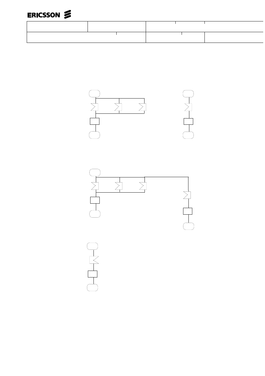
•
By the existence of a graph containing the specific combination of
STATE and SIGNAL.
•
The STATE or SIGNAL stated within parenthesis after the asterisk
is not included in the asterisk. Several STATES or SIGNALS can
be stated at the same time by using comma as a separator
The star notation may only be used for either the STATE or the SIGNAL RECEP-
TION symbol in each sequence, that is, a star state followed by a star signal is not
allowed
Use of star notation may lead to confusion. For example, if a transition is stated as
’STATE * receives SIGNAL B ’ and another transition states ’STATE A receives
SIGNAL *’. Which of these transitions describes the transition ’STATE A receives
SIGNAL B’?
Uppgjord - Prepared
Dokansv/Godkänd - Doc respons/Approved
Faktaansvarig - Subject responsible
Kontr - Checked
Nr - No.
Datum - Date
File
Rev
WORK INSTRUCTION
21 (00)
2/000 21-FCK 114 20 Uen
1996-01-01
D
The answer is ’STATE * receives SIGNAL B’. Explicit signals have higher prece-
dence than explicit states. This type of confusions can be avoided with use of
parenthesis as described above. In this example, the second transition should have
been ’STATE A receives SIGNAL *(B)’, that is, ’STATE A receives SIGNAL *
EXCEPT B’.
10.3
Hyphen Notation (-)
The following rule is valid only within the State-Transition model.
The hyphen (-) may be used with NEXT-STATE symbols to show that the NEXT-
STATE represents the same state as the IN-STATE. This is useful when multiple
names are given for the IN-STATE symbol. The hyphen means that the transition
ends in the same state as it began.
Examples of use of star and hyphen are shown elsewhere in this document.
10.4
Identifiers
Certain rules should be followed for an identifier. The reason is that references be-
tween different symbols can automatically be created when a document is printed. If
there are any connections between OUT CONNECTORS and IN CONNECTORS or
MACRO CALL and MACRO BEGIN, then page references will be added.
Page references between different symbols are based on the first <name> in the
symbol text according to the following rules.
<name> : : = {
<alphanumeric> |
<full stop> |
<underline> }*
<end of name>
<end of name> : : = {
<alphanumeric>
| <full stop>
A <name> must contain at least one <alphanumeric>
<alphanumeric> : : =
letter between A-Z,a-z
| digit 0-9
<underline> : : =
-
<full stop>: : =
.
The first 30 characters in a name are significant for the page reference.
The combination <underline> followed by one or more control characters (for exam-
ple, new line) are not regarded as a part of the name. This use of underline allows a
name to be split over more than one line. To have an underline at the same position
as a split, use two underlines.
A name is terminated by the first space or any control character (not stated in com-
bination with <underline>) or any other character which cannot be a part of the
name according to the rules specified above.
Uppgjord - Prepared
Dokansv/Godkänd - Doc respons/Approved
Faktaansvarig - Subject responsible
Kontr - Checked
Nr - No.
Datum - Date
File
Rev
WORK INSTRUCTION
22 (00)
2/000 21-FCK 114 20 Uen
1996-01-01
D
The character / immediately followed by the character * always starts a comment.
The character * immediately followed by the character / always terminates a com-
ment. Any character can be included in a comment text. Comment text using this
notation can be inserted before or after a name.
A comment can also start with a left bracket. In such cases all the remaining symbol
text is regarded as comment text.
The following examples show how the formatter interprets symbol text.
Symbol Text
Name
Comment
123 This
123
Space Terminates name
123 This
123
Leading spaces ignored
ALFA%Beta
ALFA
% terminates name
1. Connect
1.
Dot legal character
1_2
1_2
Underline legal character
A_ B
AB
Underline at end of line = name
continues on next line
A_ _ B
A_B
If underline at split, use two
CONNect
CONNect
Difference between lower case
and upper case letters
/*Comment*/XX
XX
Comment before name
XX/*Comment*/
XX
Comment terminates name
11
DRAWING CONVENTIONS OF FLOW
DESCRIPTIONS
Flows are drawn using the basic symbols, flow lines, connectors, and associated
texts. Flows are generally drawn from top to bottom. Sequences are implied when
one symbol is placed above a second symbol, and they are connected with a flow
line. There is no implied sequence when two or more symbols are connected by a
horizontal flow line.
Convergence may be shown between branches of a transition that are placed on the
same page of a document. Convergence may also be shown by two or more
out-connector symbols connected with the same in-connector symbol.
A flow may diverge into several branches. If all branches of a flow cannot be drawn
on the same page of the document, a connector can be used.
Use capital letters for names (for example, states, signals, commands, block names
..).
Indicate with a comment ’comb’ if a combined signal is used.
When using the LOOP DELIMITERS, comment on the condition for the iteration
by using constructs such as DO WHILE or DO UNTIL.

Uppgjord - Prepared
Dokansv/Godkänd - Doc respons/Approved
Faktaansvarig - Subject responsible
Kontr - Checked
Nr - No.
Datum - Date
File
Rev
WORK INSTRUCTION
23 (00)
2/000 21-FCK 114 20 Uen
1996-01-01
D
Draw top to bottom, left to right.
Avoid line crossings.
Put emphasis on
•
External interwork (comment on important info conveyed by a
signal)
•
Important decisions
•
What is being done, not details in how.
Degree of detail in flows
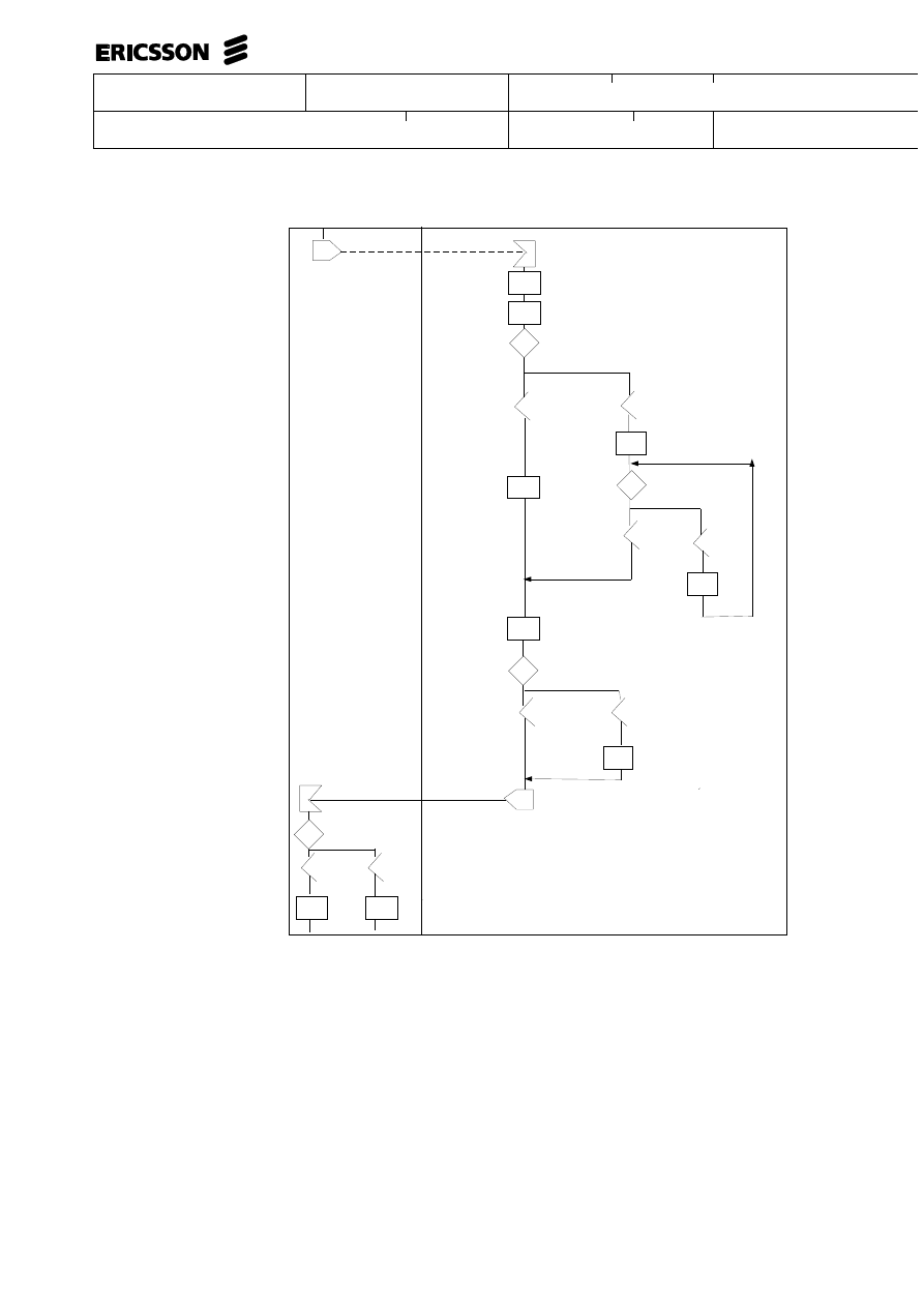
Example of a flow (not complete) with an excess of details, that is, . details that do
not affect the interface.
Uppgjord - Prepared
Dokansv/Godkänd - Doc respons/Approved
Faktaansvarig - Subject responsible
Kontr - Checked
Nr - No.
Datum - Date
File
Rev
WORK INSTRUCTION
24 (00)
2/000 21-FCK 114 20 Uen
1996-01-01
D
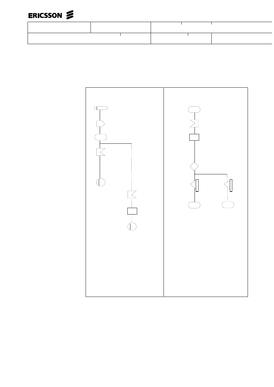
SIG5
Set result
code
Task D
Task A
Task B
Task C
Task E
Search
Result
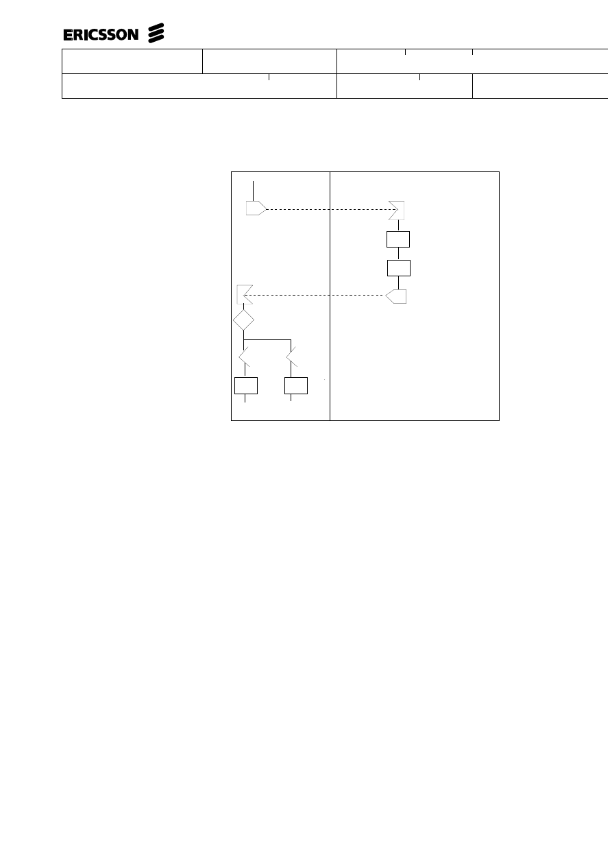
Example (incomplete) of a flow regarding the level of detail.
The same behaviour as in the previous example is described, but a more appropriate
level of detail is selected.
Several measures can be summarised in one box and assigned descriptive names.
Note that in a comment on SIG5, signal data has been stated. This is necessary, par-
ticularly if the signal data is to influence the measures at the receiving end. Here the
source of the signal data ’Search Result’ obviously comes from the task box
“Search”. If not obvious, it should be made clear for example, by a comment at the
task box (for example, “Output = Search result”.)
Uppgjord - Prepared
Dokansv/Godkänd - Doc respons/Approved
Faktaansvarig - Subject responsible
Kontr - Checked
Nr - No.
Datum - Date
File
Rev
WORK INSTRUCTION
25 (00)
2/000 21-FCK 114 20 Uen
1996-01-01
D
SIG5
Search result
Task A,B,C,D,E
Search
/* With search
result*/
Uppgjord - Prepared
Dokansv/Godkänd - Doc respons/Approved
Faktaansvarig - Subject responsible
Kontr - Checked
Nr - No.
Datum - Date
File
Rev
WORK INSTRUCTION
26 (00)
2/000 21-FCK 114 20 Uen
1996-01-01
D
12
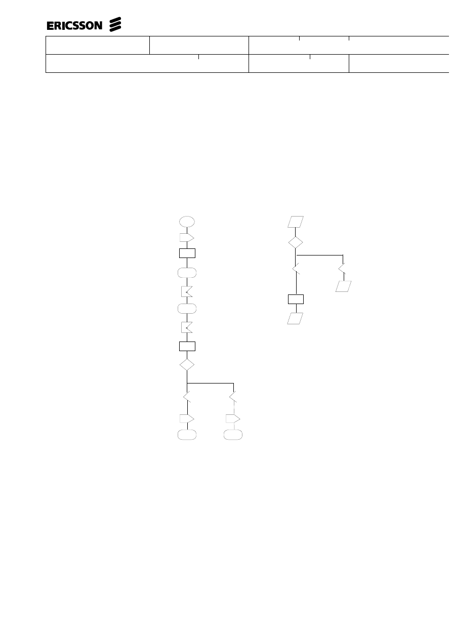
EXAMPLES
12.1
Some examples using basic Description Elements
State-transition
model
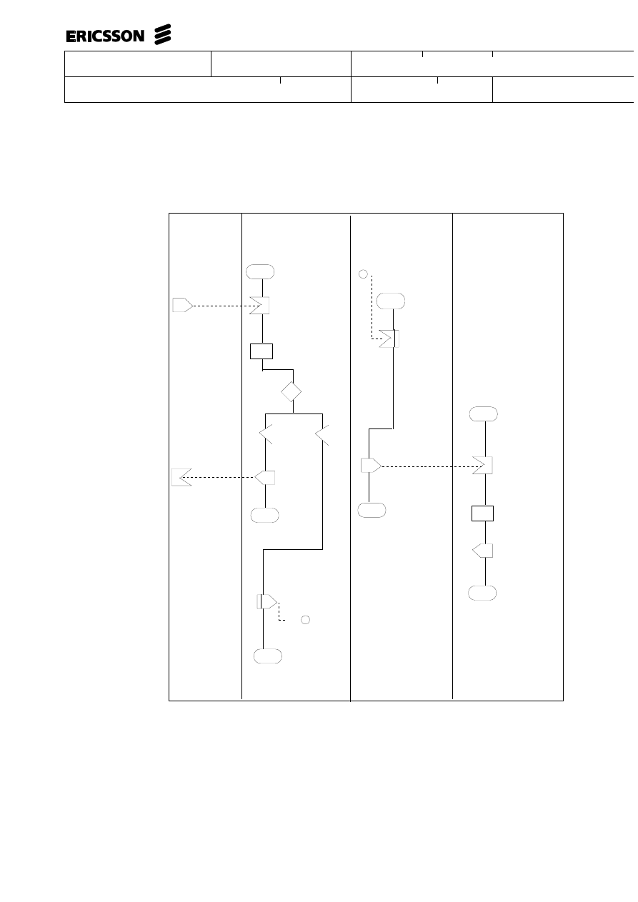
INITSUPERV
Set start values for
supervision
IDLE
INITSUPERVACK
RESERVE
SEIZE
Accumulate call counter
Check condition
for seizure
Cong
Seized
CONG
SEIZEACK
IDLE
BUSY
Event-Sequence Model
COMMAND
DUDAC
Command
accepted
Yes
No
Set
supervision
data
PRINTOUT
EXECUTED
PRINTOUT
NOT_ACCEPTED
Uppgjord - Prepared
Dokansv/Godkänd - Doc respons/Approved
Faktaansvarig - Subject responsible
Kontr - Checked
Nr - No.
Datum - Date
File
Rev
WORK INSTRUCTION
27 (00)
2/000 21-FCK 114 20 Uen
1996-01-01
D
Macro and Macro definition
IDLE
SEIZEIND
Select_route
[P.28
BUSY
Sendcong
[P.28
CONG
IDLE
Select_route
[P.28
Evaluate type of call
Check result
Ord. call
Subscr. service
SEIZEACK
SEIZEACK2
Select_route
Select_route
IDLE
SEIZE
Accumulate call counter
Sendcong
[P.28
Connector
Uppgjord - Prepared
Dokansv/Godkänd - Doc respons/Approved
Faktaansvarig - Subject responsible
Kontr - Checked
Nr - No.
Datum - Date
File
Rev
WORK INSTRUCTION
28 (00)
2/000 21-FCK 114 20 Uen
1996-01-01
D
Iteration by using the iteration symbol
IDLE
SEIZE
Check Blocktypes
/* DO UNTIL all blocktypes are checked*/
Compare block reference
Check
Trunk
Else
SEIZER
SEIZEACK
Check Blocktypes
IDLE
IDLE
SEIZE
All block types are checked
No
Yes
IDLE
Compare block reference
Check
Trunk
Else
SEIZEACK
SEIZER
Iteration without using the iteration symbol
Uppgjord - Prepared
Dokansv/Godkänd - Doc respons/Approved
Faktaansvarig - Subject responsible
Kontr - Checked
Nr - No.
Datum - Date
File
Rev
WORK INSTRUCTION
29 (00)
2/000 21-FCK 114 20 Uen
1996-01-01
D
Star notation
Using star notation on STATE symbols
K
f1
D
*
L
J
In the following example, the star notation includes the combinations
STATE A with SIGNAL N, but DOES NOT include the combination
state A and signal P, since it is explicitly stated.
P
F1
D
A
f1
D
*
M
N
P
Uppgjord - Prepared
Dokansv/Godkänd - Doc respons/Approved
Faktaansvarig - Subject responsible
Kontr - Checked
Nr - No.
Datum - Date
File
Rev
WORK INSTRUCTION
30 (00)
2/000 21-FCK 114 20 Uen
1996-01-01
D
12.2
Short Notations
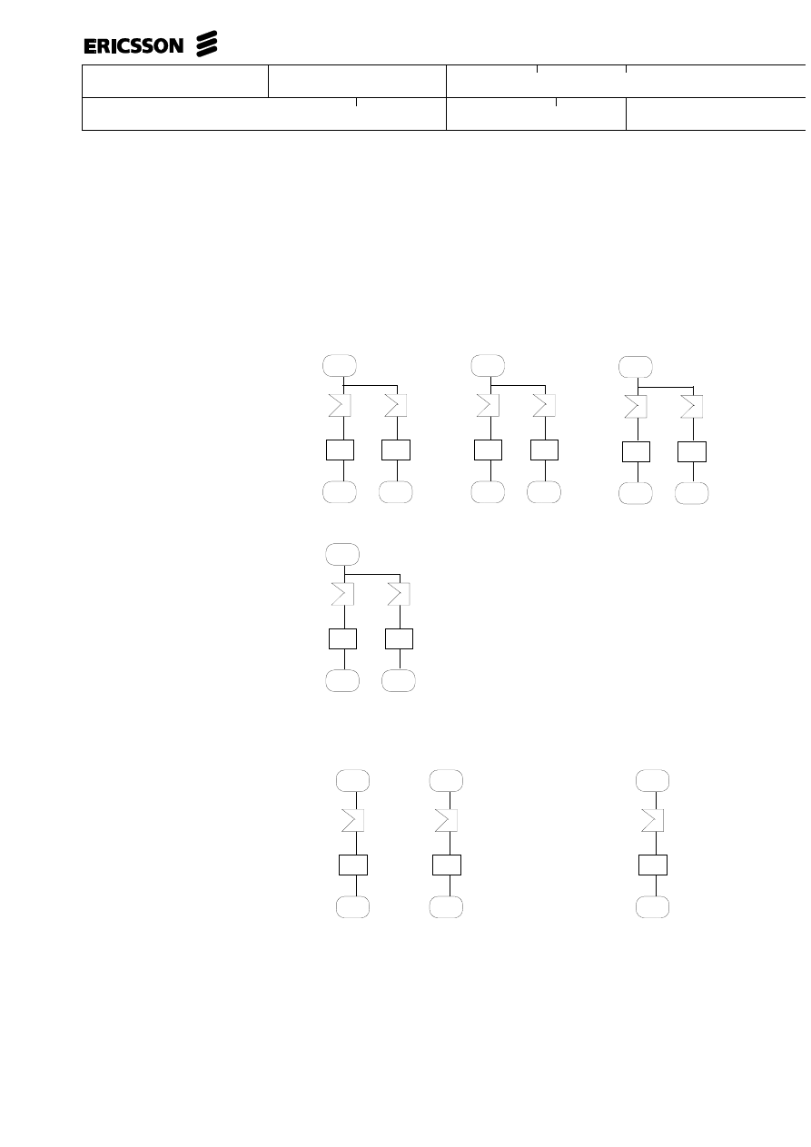
Multiple appearance of a state.
The following tree graphs can be replaced by one single graph
by merging STATE as shown below.
A
K
J
f1
f2
D
P
C
K
J
f1
f2
D
P
G
K
J
f1
f2
D
P
A,C,G
K
J
f1
f2
D
P
Hyphen Notation
The following two graphs can be replaced by one single graph by using
hyphen notation as follows.
can be replaced by
D
K
f1
D
P
K
f1
P
D,P
K
f1
_
Uppgjord - Prepared
Dokansv/Godkänd - Doc respons/Approved
Faktaansvarig - Subject responsible
Kontr - Checked
Nr - No.
Datum - Date
File
Rev
WORK INSTRUCTION
31 (00)
2/000 21-FCK 114 20 Uen
1996-01-01
D
Multiple appearance of received signals.
The following three SIGNAL RECEPTION symbols can be repllaced by one
as shown below..
A
K, J, L
f1
D
A
K
f1
D
J
L
Star notation
Else declaration for received signals by using star notation
A
K
f1
D
J
L
This part represents the
ELSE branch
/* The * stands for all
signals not explicitly
mentioned*/
f2
P
A
f1
D
(K,L)
/* This means all signals not explicitly stated in combination with
state A, EXCEPT the signals K and L */
*
*

Uppgjord - Prepared
Dokansv/Godkänd - Doc respons/Approved
Faktaansvarig - Subject responsible
Kontr - Checked
Nr - No.
Datum - Date
File
Rev
WORK INSTRUCTION
32 (00)
2/000 21-FCK 114 20 Uen
1996-01-01
D
Star notation
Using star notation on STATE symbols
K
f1
D
*
L
J
In the following example, the star notation includes the combinations
STATE A with SIGNAL N, but DOES NOT include the combination
state A and signal P, since it is explicitly stated.
P
F1
D
A
f1
D
*
M
N
P
12.3
Traffic Functions Outgoing Call
The following shows an example in which some different elements are used together
in order to describe a part of the function “Outgoing Call”.
Note that the description of the function is incomplete.
Uppgjord - Prepared
Dokansv/Godkänd - Doc respons/Approved
Faktaansvarig - Subject responsible
Kontr - Checked
Nr - No.
Datum - Date
File
Rev
WORK INSTRUCTION
33 (00)
2/000 21-FCK 114 20 Uen
1996-01-01
D
SEIZELA
LIFAULT
IDLE
SEIZELA
Subscr. line available
for traffic
NO
YES
LIFAULT
Special
circuit
YES
NO
Seize_special_
circuit
[P.36
Result
Seized
Not
seized
BUSY
Blocking
NO
YES
Mark ind. not
available for traffic
IDLE
LASEIZED
SEIZED
EXTERN
/* TCS */
Outgoing traffic in subscriber line
ALLOC: LI
Uppgjord - Prepared
Dokansv/Godkänd - Doc respons/Approved
Faktaansvarig - Subject responsible
Kontr - Checked
Nr - No.
Datum - Date
File
Rev
WORK INSTRUCTION
34 (00)
2/000 21-FCK 114 20 Uen
1996-01-01
D
SEIZELA
IDLE
SEIZELA
LOCKOUT
LOCK
/*Line lockout*/
LOCKOUT
SEIZELA
SEIZELA
BUSY
BUSY
*
_
Uppgjord - Prepared
Dokansv/Godkänd - Doc respons/Approved
Faktaansvarig - Subject responsible
Kontr - Checked
Nr - No.
Datum - Date
File
Rev
WORK INSTRUCTION
35 (00)
2/000 21-FCK 114 20 Uen
1996-01-01
D
12.3.1
Seize Special circuit
FUNC: Outgoing traffic in
subscriber line.
ALLOC:LI
FUNC:Seize of special circuit
ALLOC:SE
Seize_special_circuit
[P.34
BSEIZE
L16
SPSEIZED
/*Speech
circuit
seized */
Seize_
special_
circuit
SPCONG
/*Congestion*/
Release
special
circuit
Seize_
special_
circuit
IDLE
BSEIZE
Special circuit
handling
Task ind. seized
Yes
No
SE2
IDLE
Uppgjord - Prepared
Dokansv/Godkänd - Doc respons/Approved
Faktaansvarig - Subject responsible
Kontr - Checked
Nr - No.
Datum - Date
File
Rev
WORK INSTRUCTION
36 (00)
2/000 21-FCK 114 20 Uen
1996-01-01
D
12.3.2
Selection of channel and connect speech path
EXTERN
/* TCS */
IDLE
IDLE
IDLE
IDLE
SELIND3
REJECT
SELPIND3
Seize CJ
ind.
Cong
Yes
No
REJECT
--
CJIND
CJ_s
[P.37
CJ_s
CJIND
READLIDATA
CJB1
READLIDATA
Read Time
switch
connection data
RT,KR ref.
READLIDATAR
--
Selection of
junctor
ALLOC: CJ
Outgoing traffic
in junctor
ALLOC: CJ
Outgoing traffic in
subscriber line
ALLOC: LI
Wyszukiwarka
Podobne podstrony:
0400 Function description B Operating principle with function diagram Auxiliary heater Models 124,
0400 Function description auxiliary heater A General Models 124, 126, 201
BizAgi Functional Description
0400 Function description D Electrical function, control unit (Webasto no 105 499) Auxiliary heater
0400 Function description electrical function of control unit Auxiliary heater Models 124, 126, 201
9 16 12 2011 grammaire descrip Nieznany (2)
8 9 12 2011 grammaire descript Nieznany (2)
10 13 1 2012 grammaire descrip Nieznany (2)
1 7 10 2011 la grammaire descri Nieznany (2)
Index Function Index Function i Nieznany
Multi Language with Option Demo Nieznany
Language acquisition and univer Nieznany
9 16 12 2011 grammaire descrip Nieznany (2)
8 9 12 2011 grammaire descript Nieznany (2)
islcollective worksheets intermediate b1 elementary school spelling writing comparison language func
Three functions of the language according to Karl
#0521 – Describing Speech and Language Ability
więcej podobnych podstron