
High-Performance Context-Free Parser for
Polymorphic Malware Detection
Young H. Cho and William H. Mangione-Smith
The University of California, Los Angeles, CA 91311
{young, billms}@ee.ucla.edu
http://cares.icsl.ucla.edu
Abstract.
Due to increasing economic damage from computer network
intrusions, many routers have built-in firewalls that can classify packets
based on header information. Such classification engine can be effective
in stopping attacks that target protocol specific vulnerabilities. However,
they are not able to detect worms that are encapsulated in the packet
payload. One method used to detect such application-level attack is deep
packet inspection. Unlike the most firewalls, a system with a deep packet
inspection engine can search for one or more specific patterns in all parts
of the packets. Although deep packet inspection increases the packet
filtering effectiveness and accuracy, most of the current implementations
do not extend beyond recognizing a set of predefined regular expressions.
In this paper, we present an advanced inspection engine architecture that
is capable of recognizing language structures described by context-free
grammars. We begin by modifying a known regular expression engine to
function as the lexical analyzer. Then we build an efficient multi-threaded
parsing co-processor that processes the tokens from the lexical analyzer
according to the grammar.
1
Introduction
One effective method for detecting network attacks is called deep packet inspec-
tion. Unlike the traditional firewall methods, deep packet inspection is designed
to search and detect the entire packet for known attack signatures. However, due
to high processing requirement, implementing such a detector using a general
purpose processor is costly for 1+ gigabit network. Therefore, many researchers
have developed several cost-efficient high-performance pattern matching engines
and processors for deep packet inspection [7, 12, 13, 4, 19, 2, 8, 16, 6, 5].
Although these pattern matching filters can be powerful tools for finding sus-
picious packets in the network, they are not capable of detecting other higher-
level characteristics that are commonly found in malware. We hypothesize that
the ability to detect advanced features like the language structure and the pro-
gram dataflow can lead to more accurate and advanced form of filters.
For example, polymorphic virus such as Lexotan and W95/Puron attack by
executing the same instructions in the same order, with only garbage instruc-
tions, and jumps inserted between the core instructions differently in subsequent
2
Young H. Cho et al.
Common target instruction in viruses
CMP AX, 'ZM'
66 3D 4D 5A
Byte sequences to search for
66 3D 4D 5A
90 90 BF
Code containing the target sequence
NOP
The actual instructions
NOP
MOV EDI, 5A4D3D66
Fig. 1.
When disassembled, the code does not contain the target instruction. Thus,
the false positives can occur when only pattern matching engine is used.
generations. As illustrated in figure 1, simple pattern search can be ineffective or
prone to false positives for such attack since sequence of bytes are different based
on the locations and the content of the inserted codes are [20]. However, if the
code structure can be examined, one may be able to classify and detect an entire
sequence of polymorphic variants with one grammar. Therefore, we propose an
advanced network intrusion detection architecture that uses a hardware parser.
We begin our discussion by describing several projects related to deep packet
inspection and hardware parsing in section 2. To develop the concept of language
recognition, we briefly describe the main phases of computer programming lan-
guage parsing in section 3. Then, we present the modifications we made to our
programmable pattern match engine so that we can integrate it as a token scan-
ner of our language parser in section 4. In section 5 we complete the design with
the specialized parsing co-processor for recognizing language structure defined
by the grammar. We conclude in section 6 with discussions of design issues and
our direction for the future.
2
Related Work
Snort is one of the most widely used open source intrusion detection system
with configuration files containing updated network worm signatures. Since the
database of the signature rules are available to the public, many researchers
use it to build high performance pattern matchers for their intrusion detection
systems.
2.1
Dynamic Payload Inspection
The dynamic pattern search is the most computationally intensive process of
deep packet inspection.
Several researchers have used field programmable gate arrays to implement
search engines capable of supporting high-speed network. The researchers have
shown that the patterns can be translated into non-deterministic and determin-
istic finite state automata to effectively map on to FPGAs to perform high speed

Polymorphic Malware Detection
3
pattern detection [17, 14, 12]. The researchers have also shown that the area effi-
cient pattern detectors can be built by optimizing the group of byte comparators
that are pipelined according the patterns [7, 18, 19, 2, 8]. Our earlier works use
chains of byte comparators and read-only-memory (ROM) to reduce the amount
of logic by storing parts of the data in memory [3, 4, 6].
Others have found that pattern matching can be done efficiently using pro-
grammable memories without using reconfigurable hardware technology. Gokhal
et al. implemented a re-programmable pattern search system using content ad-
dressable memories (CAM) [13]. Dharmapurikar et al. use Bloom filters with
specialized hash functions and memories [9, 15, 16] while Yu et al. use TCAM to
build high performance pattern matcher that is able to support gigabit network
[22]. We have implemented an ASIC co-processor that can be programmed to
detect the entire Snort pattern set at a rate of more than 7.144 Gbps [5].
2.2
Language Parser Acceleration
Due to ever increasing use of the Extensible Markup Language (XML) in com-
munication, there has been some interest for hardware XML parser. Companies
such as Tarari, Datapower, and IBM have developed acceleration hardware chips
that are capable of parsing XML at a network bandwidth of gigabit per second
[10, 21].
These devices uses the underlying concepts from the software compiler tech-
nology. Therefore, we also apply these concepts in building our own hardware
parser. However, there are additional problems that needs to be considered for
using the technology in detecting hidden programs in network packet payload.
3
Language Recognition
The first objective of computer program compiler is an accurate language recog-
nition. Therefore, we examine the technologies developed for compilers for inte-
grating the advanced recognition function to our detector.
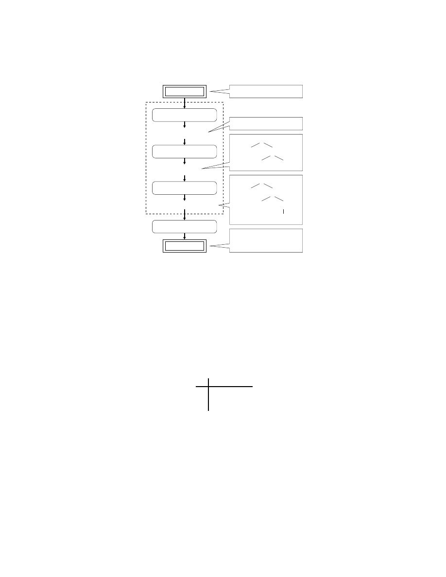
As shown in figure 2, most modern compilers work in phases where the input
is transformed from one representation to another. The first phase is called the
lexical analysis where the input program is scanned and filtered to construct
sequence of patterns called tokens. Then the sequence of tokens is forwarded to
the parser for syntactic analysis. In this phase, the syntax of the input program
is verified while also producing its parse tree. Then the parse tree is used as a
framework to check and add semantics of each functions and variables in semantic
analysis phase. The output of this analysis is used in the later stages to optimize
and generate executable code for the target architecture [1].
Lexical and syntactic analysis are mainly responsible for verifying and con-
structing software structure using the grammatical rules while semantic analysis
is responsible for detecting semantic errors and checking type usage. For our ap-
plication, we do not produce a parse tree since we are only interested in syntactic
acceptance. Therefore, we focus our research efforts to understanding lexical and
syntactical analysis of the compilers.
4
Young H. Cho et al.
mem(VAR(z)) = reg2
Parse Tree
1. Lexical Analysis
Stream of Tokens
3. Semantic Analysis
2. Syntax Analysis
Parse Tree with Semantics
Executable
z = a + 15
(VAR)(EQ)(VAR)(OP)(INT)
Source Code
4. Code Generation
EQ
VAR(z)
OP(+)
VAR(a) INT(15)
EQ
VAR(z)
OP(+)
VAR(a)
inttofloat
INT(15)
reg1 = mem(VAR(a))
reg2 = addf(reg1,15.0)
Fig. 2.
Processing phases of computer language compilers
3.1
Context Free Grammar
Many commonly used programming languages are defined with context-free
grammar (CFG). A context free grammar is a formal way to specify a class
of languages. It consists of tokens, nonterminals, a start symbol, and produc-
tions. Tokens are predefined linear patterns that are the basic vocabulary of the
grammar. In order to build a useful program structure with tokens, productions
are used. We introduce our notational convention for context free grammar with
an example often used in compiler text [1].
No. Production
1 E → E+T | T
2 T → T×F | F
3 F → (E) | id
Fig. 3.
Language syntax for a simple calculator described in CFG
The grammar in figure 3 expresses the syntax for a simple calculator. The
grammar describes the order of precedence of calculation starting with paren-
thesis, multiplication, and, finally, addition. This example consists of three pro-
ductions rules, each consisting of a nonterminal followed by an arrow and combi-
nation of nonterminals, tokens, and or symbol which is expressed with a vertical
Polymorphic Malware Detection
5
bar. The left side of the arrow can be seen as a resulting variable whereas the
right side is used to express the language syntax.
This formal representation is more powerful than the regular expression. In
addition to regular expression, it is able to represent more advanced program-
ming language structures such as balanced parenthesis and recursive statements
like “if-then-else”. Given such powerful formal representation, it may be possible
to devise more efficient and accurate signature for advanced forms of attack.
3.2
Language Processing Phases
The phase that is used for detecting tokens from regular expressions is called the
lexical analysis. In practice, the regular expressions are translated into determin-
istic (DFA) or non-deterministic finite automata (NFA). Then a state machine
is generated to recognize the pattern inputs. This machine is often referred to
as scanner.
The syntactic analysis phase follows immediately after lexical analysis. In this
phase, the grammar is used for verifying the language syntax and constructing
the syntax data structure. The processing engine of this phase is called the parser.
For modern compilers, the parsers are automatically generated according to the
rules defined in the grammars through tools such as Yacc or Bison [1, 11].
3.3
Recognizing Network Packet
Computer program source codes are analyzed with scanner and parser to deter-
mine correctness in the language structure. We propose to adapt the concept
in to the packet inspection system to effectively recognize structure within the
network traffic.
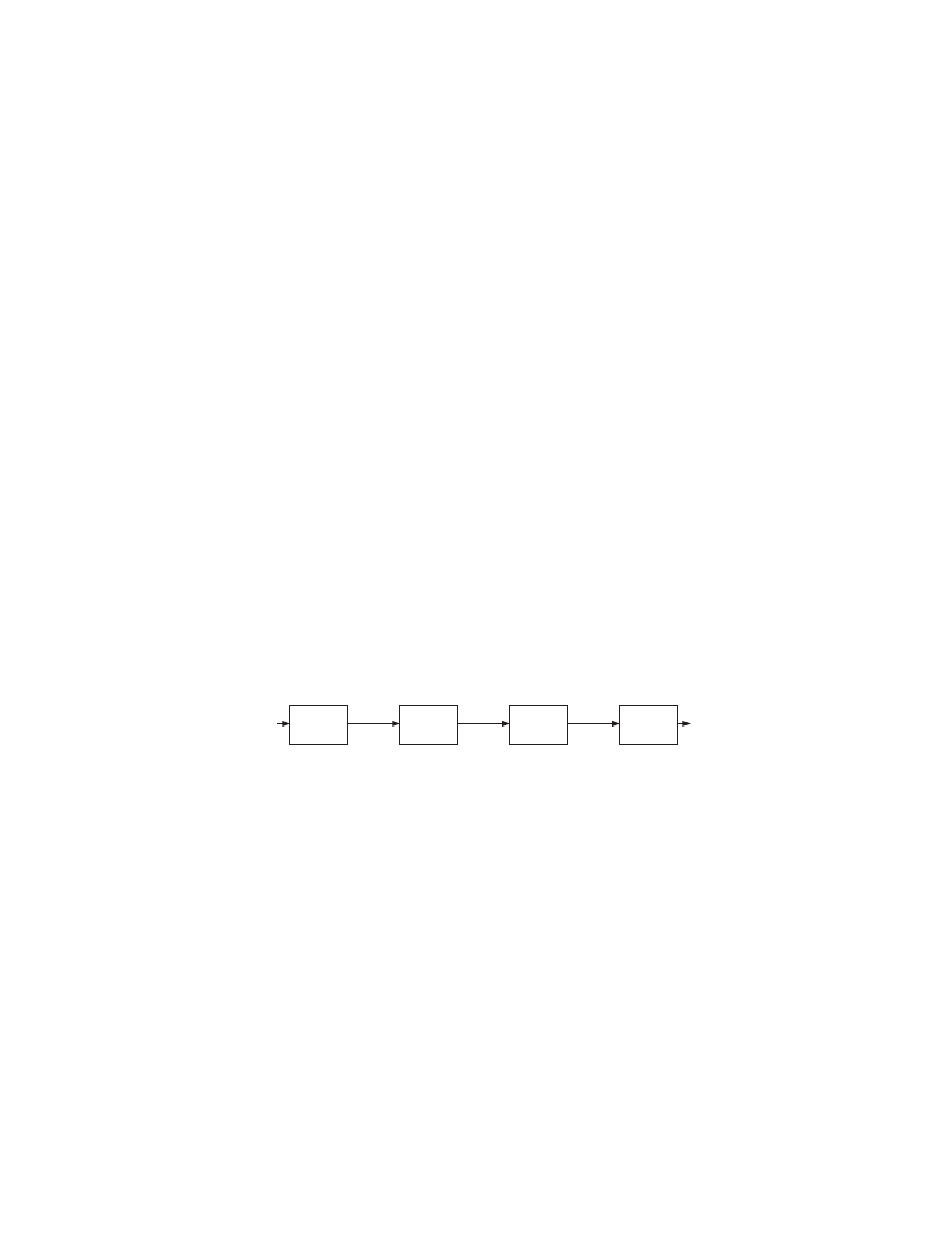
Header
Inspection
Payload
Inspection
Examine
Payload
Network
Packet
Scanner
Parser
Pattern
Index
Token
Streams
Result
Fig. 4.
Processing phases of computer language compilers
Figure 4 is a block diagram of our advanced inspection process. After the
header and the payload inspection, the pattern indices are converted to the
streams of tokens by the scanner. The streams of tokens are then forwarded to
the hardware parser to verify its grammatical structure. When the parser finds
that the token stream conforms to the grammar, the packet can be marked to
be suspicious.
4
Input Data Scanner
The first phase of language recognition is the conversion of sequence of bytes
to sequence of predefined tokens. There are several similarities between a token

6
Young H. Cho et al.
scanner and the signature matcher designs discussed previously. Both systems
are responsible for detecting and identifying predefined byte patterns from the
stream of data input. The scanner is provided with a point in the input stream
at which it is to produce sequence of tokens. Therefore, the token sequence
produced by a lexical scanner is unique. On the other hand, a signature matcher
does not constrain where the embedded string starts; it simply detects matching
patterns as it scans the stream at every byte offset [5].
4.1
Token Stream
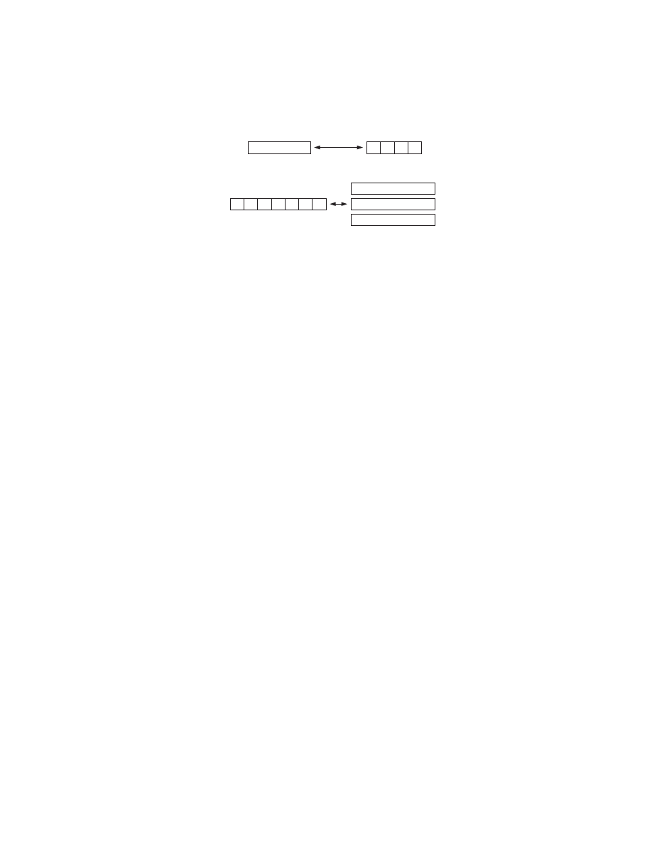
For our application, it is not possible predict the start of a malicious code before
processing begins. Thus, every token must be searched for at every byte offset
to have complete intrusion detection. When a token is detected at a given byte
offset, the scanner will insert its offset to the output stream regardless of other
tokens that might overlap the pattern. Since no two consecutive tokens from
scanner input should overlap each other, the output must be reformed into one
or more valid token streams.
A specific attack scheme can often embed its payload at more than one
location within a packet. Therefore, the scanner has to look for tokens at every
byte alignment. Furthermore, the scanner maybe looking for several starting
tokens for grammars representing different classes of attacks.
this_is_an_example
3. example
1. ample
2. an
4. his
5. is
6. this
Pattern List
is
an
example
is
an
example
is
an
example
is
ample
his
this
Fig. 5.
Multiple Token Streams from Single Data Stream
Figure 5 is an example of how one input byte stream maybe properly recog-
nized as four independent token streams. If we knew where the code started, as
with compilers, only one of the four streams would be of interest. Since the code
of the attack may be located anywhere in the payload, all four streams must
be considered viable threats. Therefore we have modified our pattern scanner to
produce multiple streams.
In order to keep each stream separate, we modify our high-performance pat-
tern matcher to provide pattern length and detection time information. When
Polymorphic Malware Detection
7
we reexamined our matcher design, we found that the pattern length informa-
tion is loaded from the memory during the pattern matching process. Therefore,
obtaining the length is simply a matter of synchronizing and outputting it with
the index number. We also learn from the design that the index output is re-
timed to synchronize with the first byte of the detected pattern in the input.
Since the purpose of the time stamp is to show the relative cycle count between
detections, it is sufficient to use the output of a simple counter that increments
every cycle [6, 5].
A
B
A>B
A=B
Comparator
FIFO Control(N)
Valid
Ena(N)
Next Idx Time
Current Idx Time
A
B
Adder
Current
Idx Time
Pattern
Length
Next
Idx Time
FIFO
Control(0)
FIFO(0)
FIFO(1)
FIFO(m)
Current
Index
Ena(0)
FIFO
Control(1)
Ena(1)
FIFO
Control(m)
Ena(m)
Index
Seq(0)
Index
Seq(1)
Index
Seq(m)
Reset
Gap(N)
Gap(0)
Gap(1)
Gap(m)
Reset
Register
D
Q
ENA
Gap(0:N-1),N>0
ground,N=0
RST
Or
And
Gap(N)
Ena(0:N-1)
Init(N)
Init(N)
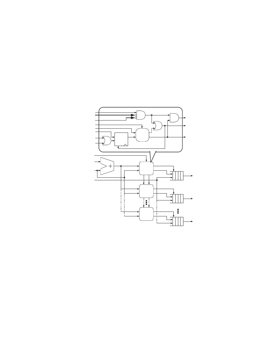
Fig. 6.
Token stream splitter
Once we have index, length, and time of a detected token, we can determine
whether any two tokens can belong to the same stream. As shown in figure 6,
the length of a newly detected token is added to the detection time and stored
in the register of an available FIFO control. Since each byte is processed in every
cycle, this sum represents when the next valid token is expected to arrive within
the same stream. Then, when the next pattern is detected, its detection time is
compared with the value stored in the register. If the time stamp is less than the
stored value, it means that the two consecutive patterns are overlapping. So, the
token may not be stored in the FIFO. If the time stamp is equal to the stored
8
Young H. Cho et al.
value, the index is stored in the FIFO since it indicates that the patterns abut.
Finally, when the time stamp is greater than the stored value, it indicates that
there was a gap between the token. Thus, if the token is not accepted by any
other active FIFOs, it is stored along with a flag to show that there was a gap
between the current token and the previous token.
Number of required FIFOs can vary depending on how the grammar and
tokens are defined. Whenever one token is a substring of another pattern or
concatenation of multiple patterns, it introduces the possibility of having one
more valid token stream. Therefore, grammar can be written to produce infinite
number of token streams. When all the FIFOs become unavailable, the design
can stall the pipeline until one of the FIFO become available or simply mark
the packet in question as suspicious. However, such problem rarely occur and
may be avoided by rewriting the token list and grammar to contain only the
non-overlapping patterns.
4.2
Token Threads
Although the original pattern stream is transformed into number valid token
streams, there is more work that needs to be done to find the start token.
this | that
Verb
Pronoun
is | was
Noun
example
Sentence
Pronoun Verb Pronoun Noun
Example Input
Example Grammar
that was this is that example
Potential starting
token of Sentence
that was this is
this is that example
Thread 1:
Thread 2:
xxxxxxxxxx
xxxxxxxxxx
xxxxxxxxxx
xxxxxxxxxx
xxxxxxxxxx
xxxxxxxxx
xxxxxxxxx
xxxxxxxxx
xxxxxxxxx
xxxxxxxxx
Expected Noun, but found Verb
Valid Parser Threads and Results
Successfully parsed
Fig. 7.
Multiple pattern threads in a single token sequence
Figure 7 shows that finding the start token of a sentence requires a higher
level of language recognition. More than one token sequence that satisfy the
grammar can overlap throughout the entire token stream.
We resolve this problem by assuming that every token is a starting token of
the stream. In this solution, a stream with N tokens can be seen as N independent
structures starting at different token offsets. Since each of these structures needs
to be processed separately, we refer to them as Token threads.
We have developed an algorithm for constructing pattern threads (details are
beyond the scope of this paper.) This algorithm uses memory and registers to
Polymorphic Malware Detection
9
simulate the FIFO while maintaining the list of pattern thread pointers. For a
small number of threads, specialized logic design may be easy to implement, but
maintaining a larger number of threads maybe more cost effective to implement
using a microcontroller.
5
Parser based Filter
Top-down parsers reorganize the syntactic structure of sentences by determining
the content of the root node then filling in the corresponding leaf nodes as the
program is processed in order. Bottom-up parsers, on the other hand, scans
through sentences to determine the leaves of the branches before reducing up
towards the root. In following sections we will discuss two representative classes
of grammar and the corresponding parser designs which we modify and integrate
in to our advanced filter.
5.1
Top-down Parsing
A predictive parser is one form of top-down parser. A predictive parser processes
tokens from beginning to end to determine the syntactic structure of the input
without backtracking to the previously processed tokens. The class of grammar
that can be used to derive leftmost derivation of the program using the predictive
parser is called LL grammar. The language described with an LL(n) grammar
can be parsed by looking n tokens following the current token at hand.
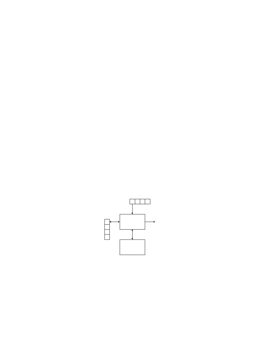
Output
X
Y
Z
$
Stack
Memory
Parsing Table
Predictive
Parser
a
+
b
$
Token Sequence
Fig. 8.
LL Parser: Left to right processing with leftmost derivation
Figure 8 is a block diagram of table-driven predictive parser. The token
sequence is buffered in order, allowing the parser to look at downstream tokens.
The stack in the system retains the state of the parser production.

10
Young H. Cho et al.
5.2
LL(1) Grammar Parsing
The simplest class of LL grammar is LL(1) where only a single token in the buffer
is accessible to the parser at any one processing step. Since LL(1) grammar only
requires the current state of the production and a single token to determine the
next action, a 2-dimensional table can be formed to index all of the productions.
A proper LL(1) grammar guarantees that for any given non-terminal symbol
and token, next grammar production can be determined. Therefore, all grammar
productions are stored in the parsing table according to corresponding non-
terminals and tokens.
When parsing begins, the stack contains the start symbol of the grammar.
At every processing step, the parser accesses the token buffer and the top of
stack. If the parser detects that the new non-terminal is at the top of the stack,
the first token in the buffer and the non-terminal is used the generate a memory
index. At this time, the combination of symbols that do not have any production
will trigger an error. Otherwise, the parser pops the non-terminal from the stack
and uses the index to load and push the right side of the production onto the
stack.
Whenever the top of stack is terminal term, it is compared with the token
on the buffer. If two are the same, the token on the stack is popped as the buffer
advance. If they do not match, parsing error is detected.
The operation of the parser simply pushes the the corresponding terms in
the table according to the non-terminal symbol at the top of the stack and the
token buffer. Then as terminals in the productions are matched up with the
token buffer, the FIFO and the terminals are removed for the next action.
5.3
LL(1) Parsing Processor
We can take the concepts of LL(1) parser and implement it into a specialized
processor.
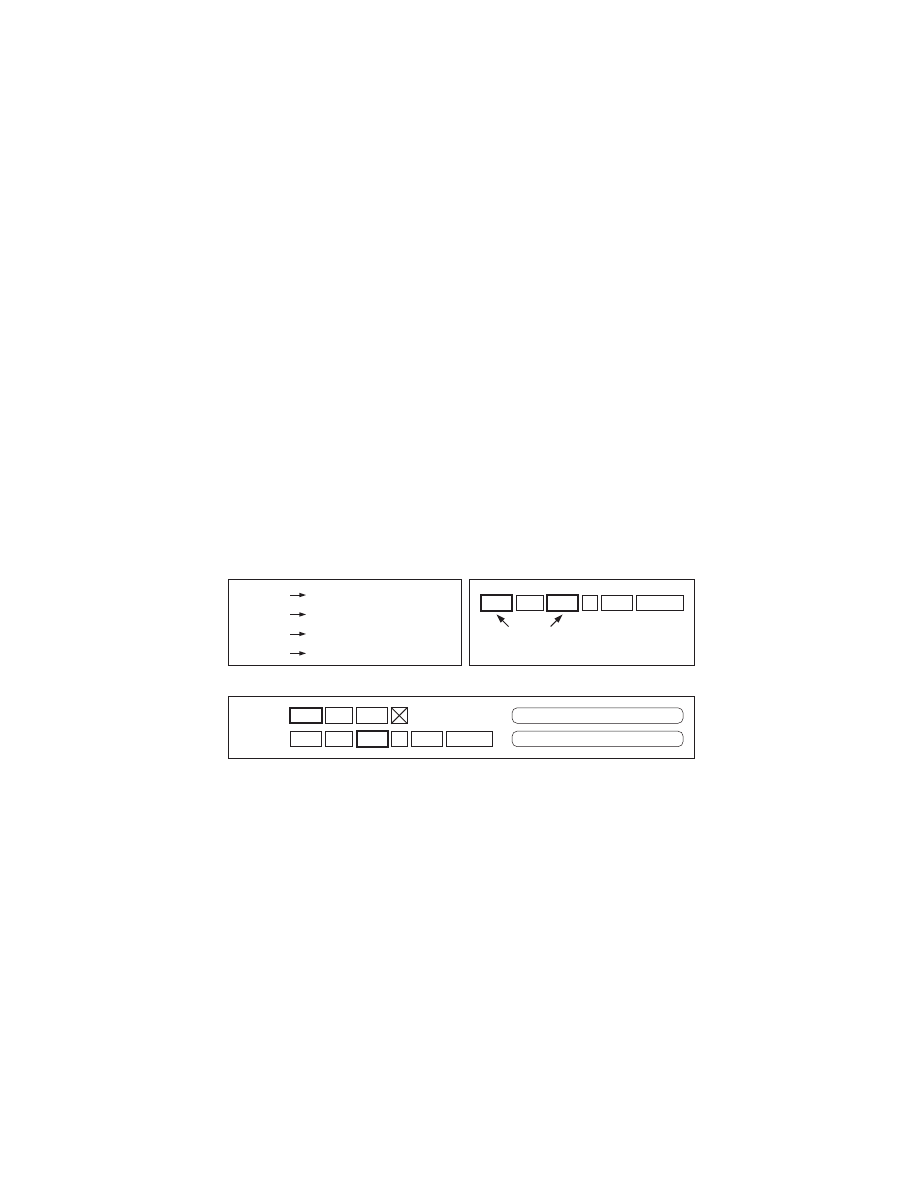
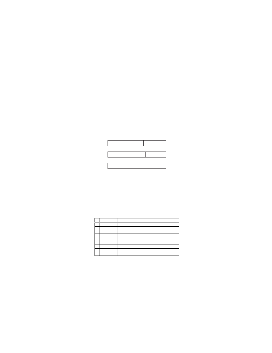
OPCODE
TERM ID
Push-type instruction
COMP
OPCODE
Pop-type instruction
OPCODE
Reset-type instruction
TYPE
TYPE
OPCODE
Jump-type instruction
ADDRESS
Fig. 9.
Instruction types for LL(1) parser
Polymorphic Malware Detection
11
From our study of the LL(1) parsing, we have devised an instruction set
architecture consisting seven operations classified into four types as shown in
figure 9 and table 1.
Instruction Function
1
JUMP(X) • Jump to address X
2a PUSH(X) • Push term X into the stack
•
Jump to the current address+1
2b PUSHC(X) • Push term X into the stack
•
Compare the stack output with the token
3a
POP
•
Pop the stack
•
Compare the stack output with the token
3b
NOPOP
•
Compare the stack output with the token
4a
RESET
•
Reset the stack pointer
•
Push start term into the stack
4b
ERROR
•
Reset the stack pointer
•
Push start term into the stack
Table 1.
Microcode for LL(1) parser instructions
With an exception of instances where more than one symbol must be pushed
into the stack, each table entry can be directly translated into a single instruc-
tion. Just like the parsing description, the address of the memory is obtained
from stack and token buffer output. As for the exception, the memory address
is obtained from the jump instruction which directs the processor to portions of
the memory where the multiple number of instructions are executed sequentially.
Once all the table entries are translated, the instructions can be stored in to a
single memory, in order.
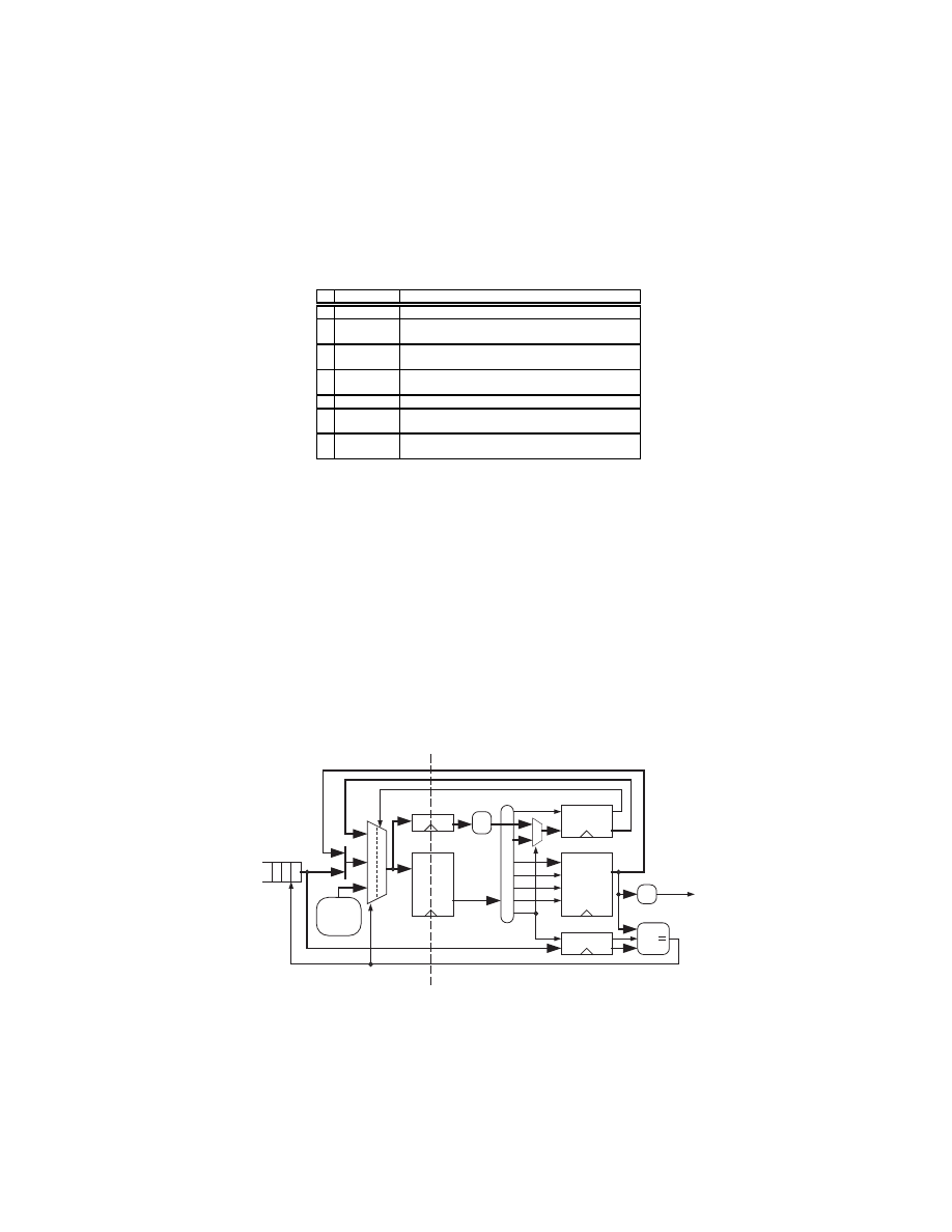
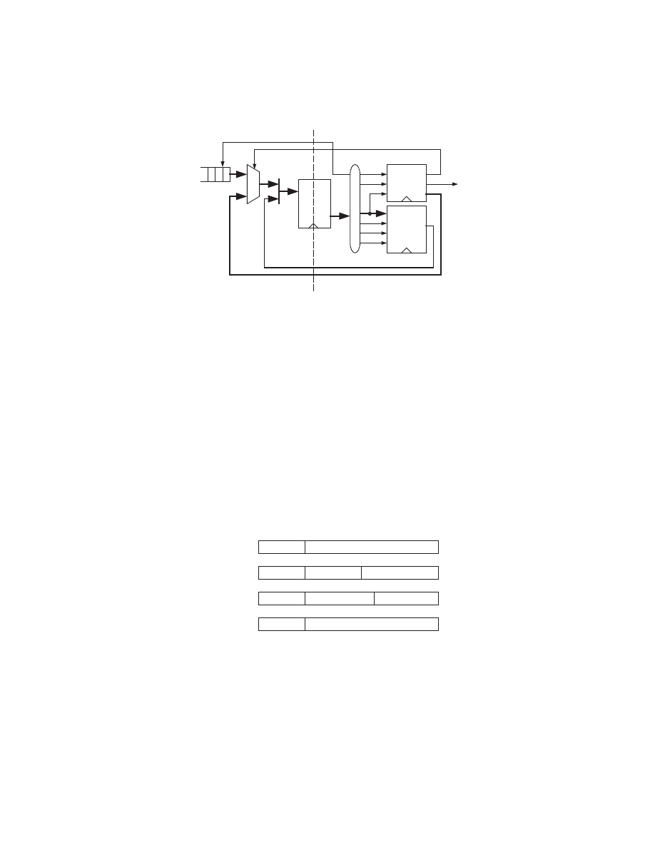
Addr
Data
Memory
0 0
0 1
Reset
Push
Pop
Term
Top
Stack
D
Q
Register
Instr Decode
FIFO
Register
D
Q
Comparator
en
comp
1 X
Address
for Pop-
Compare
A
B
match
jump
=$ accept
Register
D
Q
+1
1
0
addr
FETCH
EXECUTE
Fig. 10.
Logic design for LL(1) parser
12
Young H. Cho et al.
Based on the microcode definitions for each instruction, we can design a co-
processor in figure 10. The parser is a 2-stage pipelined processor that consists
of instruction fetch stage followed by stack processing stage. Since subsequent
iteration of instructions are dependent on each other, each stage of the pipeline
should process data independent instructions. Therefore, our design is utilized
optimally only when two or more independent processing threads are executed
simultaneously.
5.4
Bottom-up Parsing
Like LL(1) parsing, the simplest form of LR (or bottom-up) parsing is LR(1)
which uses 1 token lookahead.
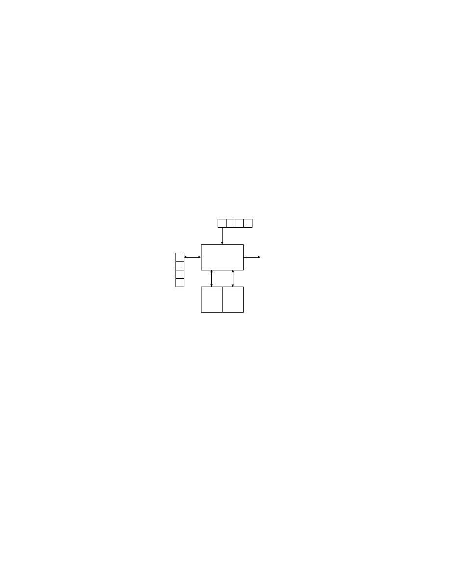
...
LR
Parser
a
+
b
$
Token Sequence
Output
Mem1
Action
Mem2
Goto
Stack
S
n
...
...
Fig. 11.
LR Parser: Left to right processing with rightmost derivation
Figure 11 is a block diagram of table driven LR parser. The stack is used to
keep track of state information instead of the specific production terms. There-
fore, the parsing process and the tables contain different information. An LR
parser has two tables instead of one, requiring two consecutive table look-up for
one parser action.
As with LL parsing, the grammar productions may need to be reformed to
satisfy the parser constraints. Since the production terms are used to generate
the contents of the table entries, during the parsing process the non-terminals
on the left side of the arrow and the production element counts are used instead
of the terms themselves.
Generating LR parsing tables from a grammar is not as intuitive process as
LL(1) parser. Therefore, most parser generators automatically generate parsing
table. Unlike the LL(1) table, there are two separate instruction look-up tables,
action and goto.
The stack is used exclusively to keep track of the state of the parser. The
action table is indexed by the top of stack entry. The action table entry contains
Polymorphic Malware Detection
13
one of four actions, shift, reduce, accept, and error. For shift action, the token
is simply shifted out of the FIFO buffer and a new synthesized state is pushed
onto the stack. The reduce action is used to pop one or more values from the
stack. Then the address for the goto table is obtained using the non-terminal
production and the parser state. The content of the goto table contains the next
state which is then pushed in to the stack for next action. When parser reaches
accept or error, the process is terminated.
5.5
LR(1) Parsing Processor
Just as we did with LL(1) parser, we have devised the instruction set and data
types for the LR(1) parser. Although the parsing process of LR(1) is not readily
obvious from the table entries, execution steps are simpler than LL(1) parsing.
OPCODE
STATE
Push-type instruction
SHIFT
OPCODE
Pop-type instruction
POPVAL
NTERM ID
OPCODE
Reset-type instruction
ACCEPT/ERROR
Fig. 12.
Instruction types for LR(1) parser
Since, at most, one state symbol can be pushed in to the stack at one iter-
ation, the jump instruction is unnecessary. Thus, there are only three types of
instructions as shown on figure 12.
Instruction Function
1a PUSH(X) • Push state X into the stack
1b PUSHS(X) • Push state X into the stack
•
Shift to the next token
2
POP(X,Y) • Pop top X states of the stack
•
Use the Goto table with non-term Y
3a
RESET
•
Reset the stack pointer
3b
ERROR
•
Reset the stack pointer
3c ACCEPT • Reset the stack pointer
•
Assert the accept signal
Table 2.
Microcode for LR(1) parser instructions
The instructions themselves (table 2) are also simpler in LR(1). The only
exception is that the pop instruction requires that the stack is able to pop
multiple items. Also the stack is only popped when a reduce action is executed.
Therefore, the pop instruction will also cause the parser to access the goto table.
14
Young H. Cho et al.
Addr
Data
Memory
0
1
Reset
Push
Pop
Imm
Top
Stack
nterm
shift
D
Q
Register
accept
Instr Decode
state
FIFO
goto
FETCH
EXECUTE
Fig. 13.
Logic design for LR(1) parser
Conceptually, two separate memories are used for execution of reduce action.
However, by forwarding the output back to the input of the parser, the two
memories can be combined. When the memories are combined as shown in figure
13, the reduce action would need to automatically loop around and access the
goto table after the stack is popped during the reduce action.
Like LL(1) parser, the LR(1) parser also can be divided as 2-stage pipeline
processor. Therefore, it also would require two or more executing pattern threads
to fully utilize the engine.
5.6
Parsing Processor
OPCODE
TERM ID/STATE
Push-type
COMP/SHIFT
OPCODE
Jump-type
ADDRESS
OPCODE
Pop-type
POPVAL
NTERM/TYPE
OPCODE
Reset-type
ACCEPT/ERROR
0
0
0
0
4
5
7
8
9
8
9
8
9
8
9
7
5
6
7
7
Fig. 14.
Instruction types for the parser. For LL(1) parsing, the processor is able to
support up to 64 terms. For LR(1), grammars with up to 32 non-terminals and 256
states can be parsed.
Polymorphic Malware Detection
15
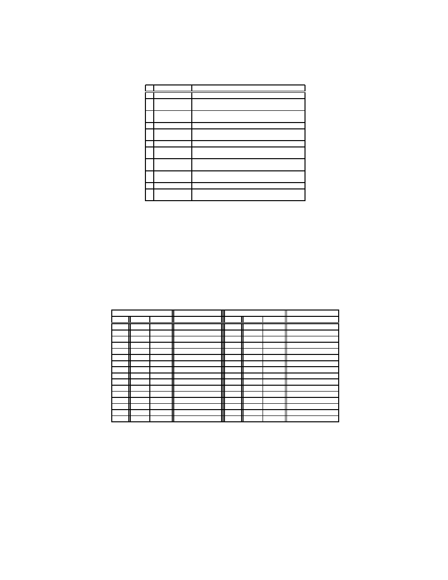
Instruction
Function
1
JUMP.l(X)
•
Jump to address X
2a
PUSH.l(X)
•
Push term X into the stack
•
Jump to the current address+1
2b PUSHC.l(X) • Push term X into the stack
•
Compare the stack output with the token
2c
PUSH.r(X)
•
Push state X into the stack
2d PUSHS.r(X) • Push state X into the stack
•
Shift to the next token
3a NOPOP.l(0,0) • Compare the stack output with the token
3b
POP.l(0,1)
•
Pop the stack
•
Compare the stack output with the token
3c
POP.r(X,Y) • Pop top X > 0 states off the stack
•
Use the Goto table with non-term Y
4a
RST/ERR.l • Reset the stack pointer
•
Push start term into the stack
4b RST/ERR.r • Reset the stack pointer
4c
ACCEPT.r
•
Reset the stack pointer
•
Assert the accept signal
Table 3.
Microcode for combined parser instructions. LL(1) instructions are labeled
with “.l” and LR(1) instructions are labeled with “.r” at the end of the instruction
name.
After examining both parser designs, we notice that the two datapath can
be combined with little effort. Therefore, a new extended set of instruction set
architecture is devised. The example instruction type shown in figure 14 is for a
parser that supports up to 64 different kinds of terms for LL(1) parsing and 32
non-terminals and 256 states for LR(1) parsing.
Address
Data
Address
Data
Addr
Term NTerm
Instruction
Addr
Term NTerm
Instruction
0
id
=0
E=0
JUMP.l(addr=5)
16-20 “×”=2
0-4
...
1
id
=0
E’=1
ERR.l
21-24
...
...
...
2
id
=0
T=2
JUMP.l(addr=13)
24
“(”=0
E=0
JUMP.l(addr=5)
3
id
=0
T’=3
ERR.l
25
“(”=0
E’=1
ERR.l
4
id
=0
F=4
PUSHC.l(0:id=0)
26
“(”=0
T=2
JUMP.l(addr=13)
5
...
...
PUSH.l(1:E’=1)
27
“(”=0
T’=3
ERR.l
6
...
...
PUSHC.l(1:T=2)
28
“(”=0
F=4
JUMP.l(addr=29)
7
...
...
unused
29
...
...
PUSH.l(0:“)”=4)
8
“+”=1
E=0
ERR.l
30
...
...
PUSH.l(1:E=0)
9
“+”=1
E’=1
JUMP.l(addr=45)
31
...
...
PUSHC.l(0:“(”=3)
10
“+”=1
T=2
ERR.l
32-36
“)”=4
0-4
...
11
“+”=1
T’=3
NOPOP.l
37-39
...
...
...
12
“+”=1
F=4
ERR.l
40-44 “$”=5
0-4
...
13
...
...
PUSH.l(1:T’=3)
45
...
...
PUSH.l(1:E’=1)
14
...
...
PUSHC.l(1:F=4)
46
...
...
PUSH.l(1:T=2)
15
...
...
unused
47
...
...
PUSHC.l(0:“×”=3)
Table 4.
LL(1) calculator parser program. Memory with 64 entries can support 16
non-terminals and 16 terminals.
Table 3 is a combined instruction set for LL(1) and LR(1) parsers. Although
the instructions are mapped in to common fields of the instruction types, the
none of the instructions are combined due to their different approach of parsing.
16
Young H. Cho et al.
Addr
Data
Memory
0 0
0 1
Reset
Push
Pop
T/S
Top
Stack
D
Q
Register
Instr Decode
FIFO
Register
D
Q
Comparator
en
comp
1 X
Address
for Pop-
Compare
A
B
match
jump
=$
accept
Register
D
Q
+1
1
0
addr
shift
1
0
nterm
term/state
nten
lr accept
FETCH
EXECUTE
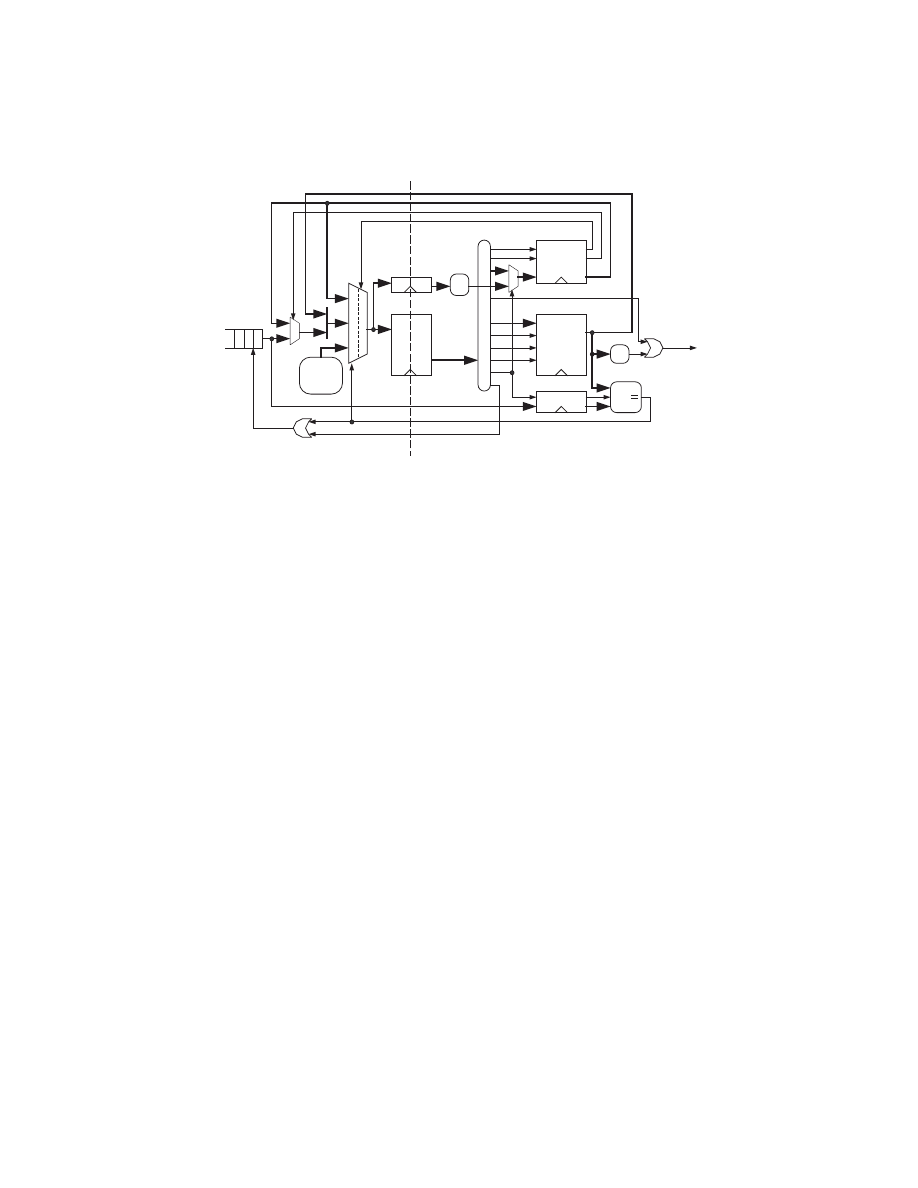
Fig. 15.
Combined parser design
According to the logic layout, all the major components can be the same for
both parsers without significant modifications. Therefore, the modified datapath
(figure 15) is not much larger than either of the parsers.
For a better understanding of our parser, the following example shows the
memory content of the parser for LL(1) grammar. Table 4 is direct direct map-
ping of the calculator example. As it is apparent from the memory content, the
order of the instructions are dependent on the terminal and non-terminal sym-
bols except when more than one symbol are to be pushed onto the stack. In such
situation, the jump instruction loads the instruction counter from a specific ad-
dress where the push instructions are executed sequentially until the last symbol
is pushed. Then the new instruction address is obtained based on the stack and
token buffer output. In LL(1) parsing, the instructions to push production terms
onto the stack are used more than once. For such cases, the jump instruction
allows the set of instructions to be reused.
In a similar manner, the tables for LR(1) parser can be expressed using the
LR(1) instruction set. The microcode for each components are determined by
the instruction decoders to correctly move the data to obtain accurate result for
both type of parsers.
5.7
Multiple Thread Parser
As we mentioned in previous sections, the parser is capable of parsing more
than a single thread. All the parsers we described above are 2-stage pipeline
processors. Therefore, the best bandwidth can be achieved when the number of
active threads are more than one. However, to shorten the critical path of the
design, one may want to increased the number of pipeline stages. In such case,
Polymorphic Malware Detection
17
xxxxx
xxxxx
xxxxx
xxxxx
xxxxx
Memory
Block Bitmap
xxxxx
xxxxx
xxxxx
xxxxx
xxxxx
xxxxx
xxxxx
xxxxx
xxxxx
xxxxx
xxxxx
Priority
Address
Encoder
Thread
Stack
Pointers
xxxxxxxxx
xxxxxxxxx
xxxxxxxxx
xxxxxxxxx
xxxxxxxxx
xxxxxxxxx
xxxxxxxxx
xxxxxxxxx
xxxxxxxxx
xxxxxxxxx
xxxxxxxxx
xxxxxxxxx
xxxxxxxxx
xxxxxxxxx
xxxxxxxxx
xxxxxxxxx
xxxxxxxxx
xxxxxxxxx
xxxxxxxxx
xxxxxxxxx
xxxxxxxxx
xxxxxxxxx
xxxxxxxxx
xxxxxxxxx
xxxxxxxxx
xxxxxxxxx
xxxxxxxxx
xxxxxxxxx
Memory
next
avail
block
Fig. 16.
Example stack that can support up to four parser threads, while efficiently
utilizing the memory. Shaded memory bitmap shows inactive blocks of the memory.
First block of each thread points to itself.
the stack that handles all of the parsing must be equipped to handle multiple
threads.
One way of achieving multi-threading is to simply have multiple stacks that
automatically rotate according to the thread. This method is requires the du-
plicate copies of control logic and for most instances, waste memory. Another
method is to simulate multiple stack by dividing the memory into multiple ad-
dress ranges. This method requires less control logic but the memory is still
wasted. Therefore, we have designed a single memory that behaves as multiple
memory by allotting chains of memory blocks for each token thread.
The basic concept of our stack design is to break the memory into smaller
blocks. By using pointers, we can then create and destroy stacks for the threads as
necessary. As shown in figure 16, the thread stack pointers are used to keep track
xxxxxxxxxxxxxxxxxxxxx
xxxxxxxxxxxxxxxxxxxxx
xxxxxxxxxxxxxxxxxxxxx
xxxxxxxxxxxxxxxxxxxxx
xxxxxxxxxxxxxxxxxxxxx
xxxxxxxxxxxxxxxxxxxxx
xxxxxxxxxxxxxxxxxxxxx
xxxxxxxxxxxxxxxxxxxxx
xxxxxxxxxxxxxxxxxxxxx
xxxxxxxxxxxxxxxxxxxxx
xxxxxxxxxxxxxxxxxxxxx
xxxxxxxxxxxxxxxxxxxxx
xxxxxxxxxxxxxxxxxxxxx
n-entry Stack
Memory
Bottom of
Stack 1
Top of
Stack 1
Bottom of
Stack 2
Top of
Stack 2
0
n
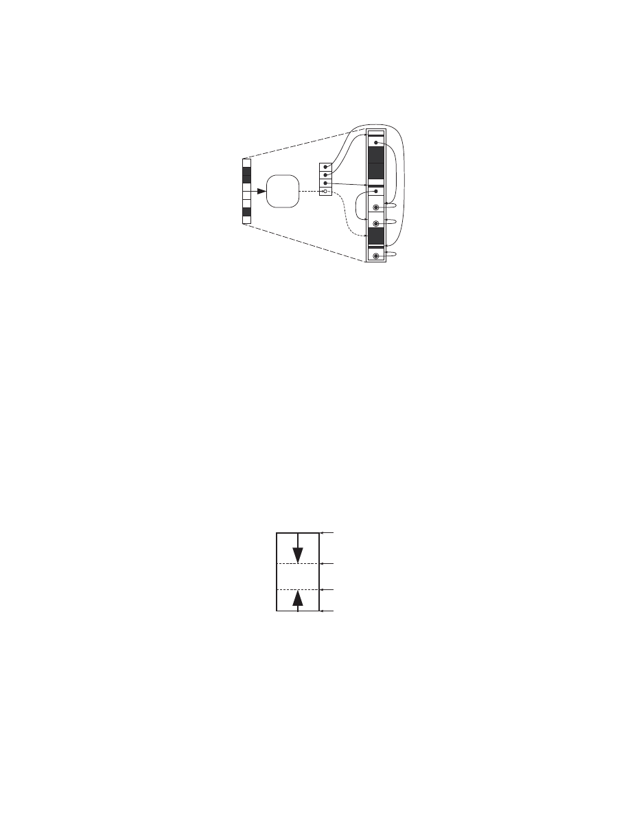
Fig. 17.
Simpler stack that can support up to two parser threads. The memory uti-
lization is optimized by allow the each stack to grow from the opposite ends of the
memory. The design must not allow the pointers to the top of the pointer to cross over.

18
Young H. Cho et al.
of valid threads. At the same time, there is a set of pointers that corresponds to
each block which is used to determine the chain of blocks that are used for each
live thread. Finally, a bitmap to indicate which memory blocks are in used. As
stacks change in size, the bitmap is used to provide the next available block.
For the parsers describe in this section, at most two threads can execute at
one time. By setting the constraint to allow execution of two threads, the stack
can be further simplified. As shown in figure 17, memory can be divided such
that one thread will push the data from top towards bottom, whereas the other
thread can push the data from bottom towards top of the memory.
6
Conclusion
In this paper, we present an advanced method for detecting computer network
intrusion. We integrate the modular context-free parser to our previously imple-
mented high-performance content inspection system. The resulting system is not
only capable of detecting several instances of string patterns, but it is capable of
detecting regular expressions as well as languages expressed in LL(1) or LR(1)
grammar.
Since network attacks are often in the form of computer programs, CFG
is a natural way to sufficiently describe their structures. However, recognizing
syntactic structure in network packet payload introduces several new issues.
The main cause of the problem for the scanner is the fact that the attacking
code can be located anywhere in the payload. First problem is to find all the valid
token streams in the payload. We accomplish this by distributing the pattern
indices into the multiple number FIFOs, ensuring that each FIFO contains valid
token streams. Second problem is to find the beginning of the attack in each
stream. Our approach is to assume that the all the tokens are start of its own
pattern thread. With this assumption, the parsing processor will attempt to
parse every one of the pattern threads. In practice, this will not incur too much
processing overhead because most threads will stop with an error after a short
execution time. This process can be accelerated if the pattern matcher flagged all
the tokens that are defined as start tokens. Given the bitmap of possible start
tokens, the parser can skip to the next flagged token when the current token
thread does not match the grammar.
Our parser is capable of parsing, at most two token threads simultaneously.
Therefore, the rest of the supporting modules can be made to handle no more
than two threads. By limiting the hardware to process two pattern threads at
any one instance, the main design components that handle the context switching
are simplified.
Finally, we make a note that our approach cannot directly detect encrypted
code. This is because the encrypted codes do not have any particular pattern
or structure that can be detectable. However, if there exist constant decoder in
the embedded code as it is with many polymorphic attacks, grammar for the
decoder can be use to find these class of attacks.

Polymorphic Malware Detection
19
References
1. A. Aho, R. Sethi, and J. Ullman. Compilers: Principles and Techniques and Tools.
Addison-Wesley, 1986.
2. Zachary K. Baker and Viktor K. Prasanna. A Methodology for Synthesis of Ef-
ficient Intrusion Detection Systems on FPGAs. In IEEE Symposium on Field-
Programmable Custom Computing Machines, Napa Valley, CA, April 2004. IEEE.
3. Young H. Cho and William H. Mangione-Smith. Deep Packet Filter with Dedicated
Logic and Read Only Memories. In IEEE Symposium on Field-Programmable
Custom Computing Machines, Napa Valley, CA, April 2004. IEEE.
4. Young H. Cho and William H. Mangione-Smith. Programmable Hardware for
Deep Packet Filtering on a Large Signature Set. In First IBM Watson P=ac2
Conference, Yorktown, NY, October 2004. IBM.
5. Young H. Cho and William H. Mangione-Smith. A Pattern Matching Co-processor
for Network Security. In IEEE/ACM 42nd Design Automation Conference, Ana-
heim, CA, June 2005. IEEE/ACM.
6. Young H. Cho and William H. Mangione-Smith. Fast Reconfiguring Deep Packet
Filter for 1+ Gigabit Network. In IEEE Symposium on Field-Programmable Cus-
tom Computing Machines, Napa Valley, CA, April 2005. IEEE.
7. Young H. Cho, Shiva Navab, and William H. Mangione-Smith. Specialized Hard-
ware for Deep Network Packet Filtering.
In 12th Conference on Field Pro-
grammable Logic and Applications, pages 452–461, Montpellier, France, September
2002. Springer-Verlag.
8. Christopher R. Clark and David E. Schimmel. Scalable Parallel Pattern-Matching
on High-Speed Networks. In IEEE Symposium on Field-Programmable Custom
Computing Machines, Napa Valley, CA, April 2004. IEEE.
9. Sarang Dharmapurikar, Praveen Krishnamurthy, Todd Sproull, and John Lock-
wood. Deep Packet Inspection using Parallel Bloom Filters. In IEEE Hot Inter-
connects 12, Stanford, CA, August 2003. IEEE Computer Society Press.
10. John Fontana. XML Vendors Set to Unveil Gigabit Speeds. Network World, Apr
2004.
11. Free Software Foundation. Bison Online Manual. GNU Free Documentation, 2002.
12. R. Franklin, D. Carver, and B. L. Hutchings. Assisting Network Intrusion Detec-
tion with Reconfigurable Hardware. In IEEE Symposium on Field-programmable
Custom Computing Machines, Napa Valley, CA, April 2002. IEEE.
13. M. Gokhale, D. Dubois, A. Dubois, M. Boorman, S. Poole, and V. Hogsett.
Granidt: Towards Gigabit Rate Network Intrusion Detection Technology. In 12th
Conference on Field Programmable Logic and Applications, pages 404–413, Mont-
pellier, France, September 2002. Springer-Verlag.
14. J. W. Lockwood. Evolvable Internet Hardware Platforms. In Proceedings of the
3rd NASA/DoD Workshop on Evolvable Hardware, pages 271–297, Long Beach,
CA, 2001. Department of Defense.
15. J.W. Lockwood, J. Moscola, M. Kulig, D. Reddick, and T. Brooks.
Internet
Worm and Virus Protection in Dynamically Reconfigurable Hardware. In Military
and Aerospace Programmable Logic Device (MAPLD), Washington DC, September
2003. NASA Office of Logic Design.
16. J. Moscola, J. Lockwood, R.P. Loui, and M. Pachos.
Implementation of a
Content-Scanning Module for an Internet Firewall. In IEEE Symposium on Field-
Programmable Custom Computing Machines, Napa Valley, CA, April 2003. IEEE.

20
Young H. Cho et al.
17. R. Sidhu and V. K. Prasanna. Fast Regular Expression Matching using FPGAs.
In IEEE Symposium on Field-Programmable Custom Computing Machines, Napa
Valley, CA, April 2001. IEEE.
18. Ioannis Sourdis and Dionisios Pnevmatikatos. Fast, Large-Scale String Match for
a 10Gbps FPGA-based Network Intrusion Detection System. In 13th Conference
on Field Programmable Logic and Applications, Lisbon, Portugal, September 2003.
Springer-Verlag.
19. Ioannis Sourdis and Dionisios Pnevmatikatos. Pre-decoded CAMs for Efficient and
High-Speed NIDS Pattern Matching. In IEEE Symposium on Field-Programmable
Custom Computing Machines, Napa Valley, CA, April 2004. IEEE.
20. Peter Szor and Peter Ferrie. Hunting for Metamorphic. Virus Bulletin Conference,
Sep 2001.
21. Jan van Lunteren, Ton Engbersen, Joe Bostian, Bill Carey, and Chris Larsson.
XML Accelerator Engine. In First International Workshop on High Performance
XML Processing, New York, NY, May 2004. ACM.
22. Fan Yu, Randy H. Katz, and T.V. Lakshman. Gigabit Rate Packet Pattern-
Matching Using TCAM. In 12th IEEE International Conference on Network Pro-
tocols (ICNP), Berlin, Germany, Oct 2004. IEEE.
Wyszukiwarka
Podobne podstrony:
A Novel High Performance Utility Interactive Photovoltaic Inverter System
Kto,blokuje tą wiedzę Antenna To Replace?tteries And Provide Unlimited Free Energy For Electric?rs
High Performance Fibers
70 1003 1019 Influence of Surface Engineering on the Performance of Tool Steels for Die Casting
how to add free tokens for skp900 obd365
Method Development in High Performance Liquid Chromatography
A Novel High Performance Utility Interactive Photovoltaic Inverter System
Are Evolutionary Rule Learning Algorithms Appropriate for Malware Detection
10 safety chain solution Safe stop0 High performance
qx high performance imager expanded capabilities
więcej podobnych podstron