A Study of the Behavior of Magnetic Microactuators
M.B. Flynn
*
and J.P. Gleeson
**
*
Dept. of Applied Mathematics, University College Cork, Ireland
and School of Physics and Astronomy, University of St.Andrews, Scotland,
mbf@st-and.ac.uk
**
National Microelectronics Research Centre and
Dept. of Applied Mathematics, University College Cork, Ireland,
j.gleeson@ucc.ie
ABSTRACT
The behavior of an idealized magnetic microactuator is
modeled and analyzed. A two parameter mass-spring model
is shown to exhibit a bifurcation from one to three steady
states as the geometry of the device is altered. In addition
we obtain solutions of the differential equation governing
the motion of a forced elastic membrane and find similar
phenomena. Stability analysis determines that in the case of
three steady states that two are stable and one is unstable.
Keywords: Magnetic microactuator, modeling, bifurcations.
1 INTRODUCTION
Many different driving mechanisms are used for
microscale devices, including electromagnetic, electrostatic,
chemical, piezoelectric and thermopneumatic actuation [1].
Magnetic actuators have the ability to produce large forces,
which allows large deflection. Electromagnetic actuation
also has the advantage of contactless movement. In this
paper we examine a simple magnetic microactuator,
following the treatment of papers [2,3,4] of electrostatic
actuation. Significant differences between magnetic
actuators and electrostatic mechanisms are that dust
particles are attracted to electrostatic devices and they often
require large voltages to achieve significant actuation.
Low-frequency magnetic fields do not attract dust particles
and will pass through a non-magnetic materials. Also they
can operate in a conductive fluid, which is a clear
advantage in the field of microfluidics. The chief
disadvantage is the unfavorable scaling of the force law at
smaller dimensions.
The paper is organized as follows. In section 2 we
formulate the governing equation for a simple mass-spring
model of the magnetic forcing. In section 3 we analyze the
model to demonstrate the existence of multiple steady-state
solutions, and introduce the full membrane model in section
4. It is shown that there are either one, two or three steady
solutions, depending upon the value of the parameters in
the model. The stability of solutions is briefly addressed in
section 5, and conclusions are discussed in section 6.
2 THE MODEL
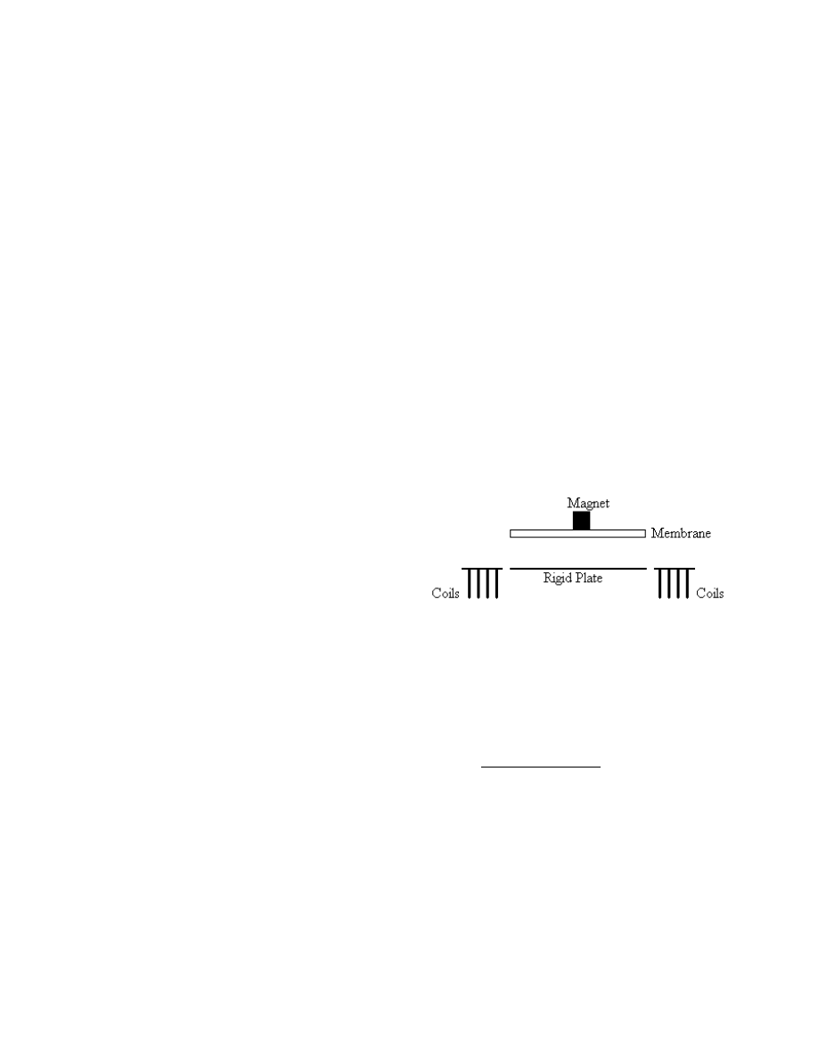
We consider an idealized device consisting of a circular
elastic membrane suspended above a rigid plate. A
cylindrical magnet of volume V and magnetic remanence B
r
is attached on top of the center of the membrane. A coil of
wire with N turns of average radius R is located beneath the
rigid plate at a distance l below the center of the magnet.
The membrane is clamped firmly along its edges. This
model is illustrated in figure 1.
Figure 1: Model of magnetically actuated device.
When a direct current I flows through the wire the
resulting magnetic field causes the plate to deflect by u
from its equilibrium position at u=0. The magnetic force
acting on the membrane is determined from the Biot-Savart
law to be
( )
( )
(
)
2
/
5
2
2
/
)
(
1
R
u
l
u
l
u
F
mag
−
+
−
=
γ
,
(1)
where
4
3/2
r
BVNIR
γ
. The restoring force of the
membrane is assumed to take the standard mass-spring
form
( )
ku
u
F
res
−
=
,
(2)
where k is the spring constant for the membrane.
We introduce the dimensionless variables w=(l-u)/l,
α
= l / R and
β
=
γ
/k. The parameter
α
characterizes the
geometry of the model and
β
the ratio between magnetic
and mechanical forces in the system. Equating the magnetic
and restoring forces leads us to the following expression for
the steady state deflection as
()
β
.
(3)
Physically relevant solutions exist in the region 0<w<1.
3 ANALYSIS
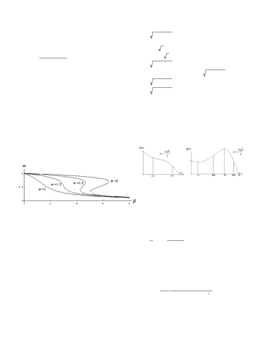
3.1 Numerical Solutions
We numerically solve equation (3) for w as a function of
α
and
β
. A bifurcation plot is shown in figure 2. For values
of
α
less than the critical value of
α
* only one solution
exists in 0<w<1. Beyond
α
* three solutions exist in
0<w<1 for a range of
β
. We have determined the first 8
digits of
α
* to be 1.6237976.
Figure 2: Bifurcation Diagram.
3.2 Functional Analysis
We wish to examine the number of solutions of
equation (3) in the region of 0<w<1. This is equivalent to
finding the roots of the polynomial
(
)
(
)
2
2
5
2
2
2
1
1
)
(
w
w
w
w
f
β
α
−
+
−
=
.
(4)
We note that f(0)=1 and that f(1)=-
β
2
. As
β
2
is always
positive, we realize that there is at least one root within
0<w<1 (if
β
≠
0).
We define the functions f
1
(w)=(w-1)
2
(1+
α
2
w
2
)
5
and
f
2
(w) =
β
2
w
2
. The polynomial f
1
(w) is of order twelve, but
has only three roots: w=1 has multiplicity two, and the
complex conjugate roots w=
±
i/
α
have multiplicity five.
The turning points of f
1
(w ) are w =1,
±
i/
α
, and
(
24
2
25
5
−
±
α
α
)/12
α
.. We require w to be real, which
means that we have either one or three turning points.
If
α
<2
6 /5=0.979796 we have one turning point at
w =1. If
α≥
2
6 /5 we have three turning points at w=1,
(
24
2
25
5
−
±
α
α
)/12
α
, we also find that there is one
point of inflection between (
24
2
25
5
−
−
α
α
)/12
α
and
(
24
2
25
5
−
+
α
α
)/12
α
as well as one between
(
24
2
25
5
−
+
α
α
)/12
α
and 1. Hence, we can determine
the shape of the curve of f
1
(w) to take one of the forms
shown in figure 3 depending on the value of
α
. The roots
of f(w) are the points at which the curve of f
1
(w) intersects
with the parabolic curve of f
2
(w). These two curves can
only intersect a maximum of three times, and so there are at
most three possible steady solutions for the mass-spring
model.
Figure 3: Shape of f
1
(w). TP is a turning point and POI
is a point of inflection.
4 FULL MEMBRANE MODEL
The steady state equation for the displacement u(r) of a
circularly symmetric membrane is given by
T
r
u
f
u
r
u
r
rr
))
(
(
1
−
=
+
,
(5)
where f(u(r)) is the external force per unit area, which in
this case is magnetic. Assuming that the force exerted by
the magnet in equation (1) acts uniformly over the whole
area of the membrane, we obtain the following expression
for f
()
()
(())
()
f
γ
,
(6)
where a is the radius of the membrane and u
o
is the
displacement of the center of the membrane. We non-
dimensionalize with v=(l-u)/R, s=r/a and
λ
=
γ
/T
π
, where
λ
is a positive number. We also define v
o
=(l-u
o
)/R. Hence
equation (5) becomes
( )
2
/
5
2
1
1
o
o
s
ss
v
v
v
s
v
+
=
+
λ
.
(7)
We must also satisfy the boundary conditions v
s
(0)=0 (as
the membrane is symmetric about r=0) and v(1)=
α
(since
the displacement u is zero at the clamped edge r=a). Noting
that equation (6) has the solution
()
2
0
5/2
2
()
41
o
o
vs
vsv
v
λ
+
+
,
(8)
which satisfies the condition v
s
(0)=0 and has v(0)=v
o
, we
impose the condition
()
(9)
to ensure the boundary condition v(1)=
α
is satisfied.
Writing v
o
=
α
w and rearranging equation (9) returns us to
equation (3), with
β
=
λ
/4. The bifurcation analysis of
section 3.1 then holds, i.e., for
α
>
α
* there exist three
possible steady states of the membrane for certain
λ
values.
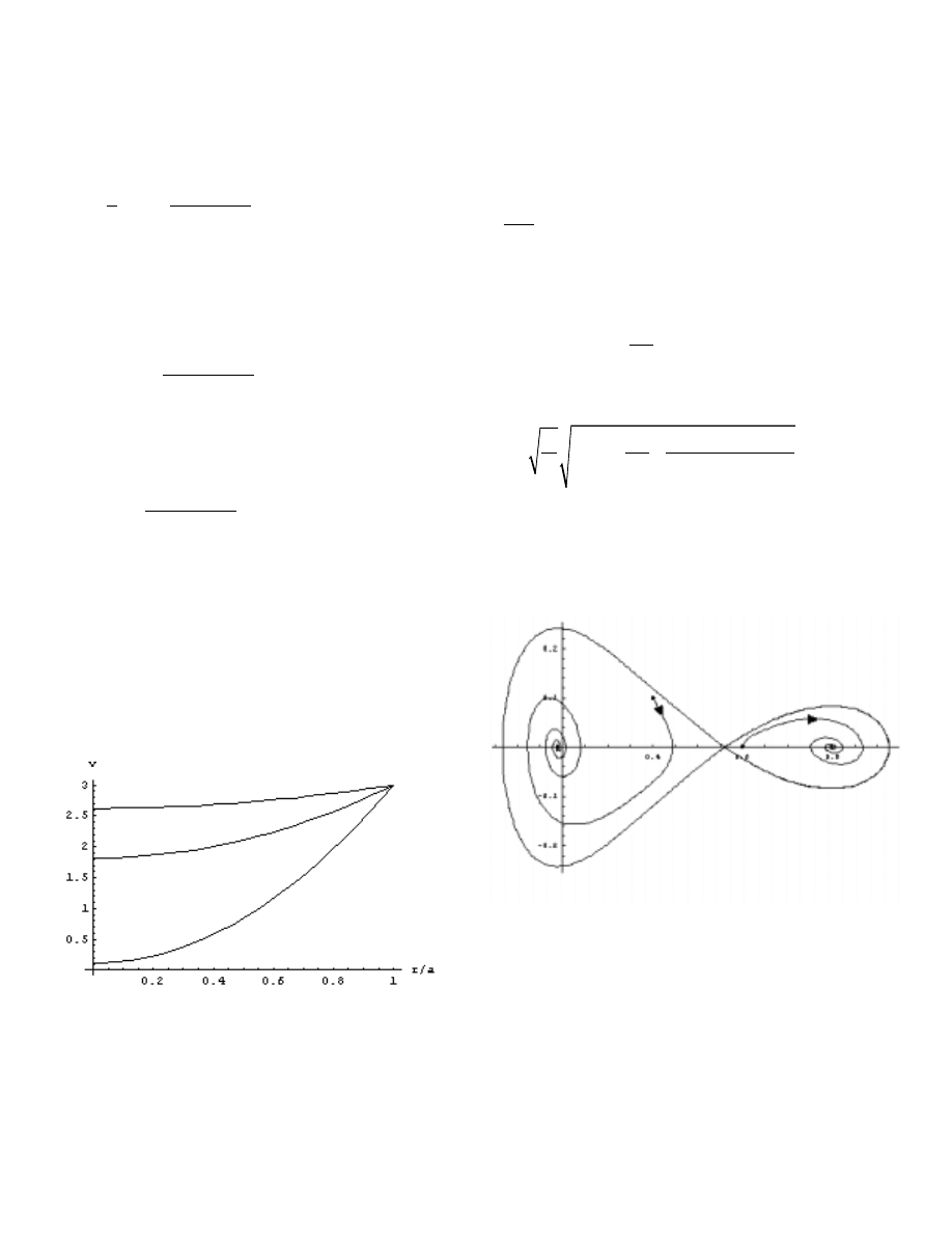
Figure 4 shows an example of the three steady states of the
membrane corresponding to
λ
=100 and
α
=3. The maximal
deflections correspond to v
o
values of approximately 0.12,
0.82 and 2.62.
Figure 4: Multiple steady states for a cylindrically
symmetric membrane. Here
λ
=100 and
α
=3.
5 STABILITY ANALYSIS
To examine the stability of the system we apply
Newton’s second law to the membrane
2
2
()
magres
du
mFFgu
dt
+
(10)
where m is the mass of the membrane. Transforming to the
variable w=(l-u)/l as in section 2 and defining the velocity
of the magnet
dw
ydt
yields the constant-energy curves for y(w):
()
y
β
,
(11)
where c is a constant. This equation describes the orbits of
the system in phase space. By adding a damping term in
equation (10) and numerically integrating we obtain
solutions such as those indicated in figure 5. This shows
one unstable and two stable equilibrium points.
Figure 5: An example of a stability diagram showing
two stable and one unstable steady states.
6 CONCLUSION
We have presented an analysis of a magnetic
microactuator similar to that discussed in [1]. Using a
simple mass-spring model we showed that up to three
steady states may exist. Similar bifurcation behavior was

shown to exist in a more sophisticated membrane model.
The analysis reveals that the geometry of the membrane is
highly influential in the bifurcation behavior. The stability
of solutions was examined and revealed the presence of
either one stable solution or two stable and one unstable
solutions. A similar model was developed to describe
experimental results in [1]; however in that work a fixed
geometry was examined and only one steady state was
reported.
The bifurcation analysis for an electrostatic micro-
actuator has been addressed in [2,3,4]: it was found that
zero to two steady solutions may exist, only one of which is
stable. Thus magnetic actuation is shown to have
qualitatively different behavior to electrostatic actuation.
By constructing a device of a suitable geometry it may be
possible to observe hysteresis effects by switching between
stable steady states, permitting the development of novel
MEMS applications.
7 ACKNOWLEDGEMENTS
One of the authors (JPG) gratefully acknowledges
funding support from the Institute for Nonlinear Science
and the Faculty of Arts Research Fund, University College
Cork.
REFERENCES
[1] D. de Bhailis, C. Murray, M. Duffy, J. Alderman, G.
Kelly, S.C. O’Mathuna, “Modelling and analysis of a
magnetic microactuator”, Sensors and Actuators, 81,
pp.285-289, 2000.
[2] J.A. Pelesko, “Multiple solutions in electrostatic
MEMS”, Proceedings of MSM 2001, pp.290-293,2001.
[3] D. Bernstein, P. Guidotti and J.A. Pelesko,
“Analytical and numerical analysis of electrostatically
actuated MEMS devices”, Proceedings of MSM 2000, pp.
489-492, 2000.
[4] D. Bernstein, P. Guidotti, J.A. Pelesko,
“Mathematical Analysis of an electrostatically actuated
MEMS Device”, Proceedings of Modelling & Simulation
of Microsystems, pp 489-492, 2000.
[5] J.A. Pelesko, X.Y. Chen, “On the Behaviour of Disk
shaped MEMS Devices”, preprint.
Wyszukiwarka
Podobne podstrony:
A Behavioral Genetic Study of the Overlap Between Personality and Parenting
A Behavioral Genetic Study of the Overlap Between Personality and Parenting
Interruption of the blood supply of femoral head an experimental study on the pathogenesis of Legg C
Pancharatnam A Study on the Computer Aided Acoustic Analysis of an Auditorium (CATT)
Nukariya; Religion Of The Samurai Study Of Zen Philosophy And Discipline In China And Japan
Effect of magnetic field on the performance of new refrigerant mixtures
Mossbauer study of the retained austenitic phase in
pharr homer and the study of greek
Book Review The Study of a Negro Policeman
The Study of Man
An experimental study on the development of a b type Stirling engine
Study of the temperature?pendence of the?initic transformation rate in a multiphase TRIP assi
Mossbauer study of the retained austenitic phase in
Interruption of the blood supply of femoral head an experimental study on the pathogenesis of Legg C
Pancharatnam A Study on the Computer Aided Acoustic Analysis of an Auditorium (CATT)
E E (Doc) Smith Lensman 07 Masters of the Vortex
Shaman Saiva and Sufi A Study of the Evolution of Malay Magic by R O Winstedt
więcej podobnych podstron