
730B4–01
–
THEFT DETERRENT & DOOR LOCK
POWER DOOR LOCK CONTROL SYSTEM
73–1
1793
Author:
Date:
2004 COROLLA (RM1037U)
POWER DOOR LOCK CONTROL SYSTEM
ON–VEHICLE INSPECTION
1.
INSPECT FOR ELECTRICAL DOOR LOCK OPERATION
HINT:
w/ Power window:
The door control switch is built in the master switch in the driver’s door and also in the passenger’s
door.
w/o Power window:
The door control switch is in the driver’s door and also in the passenger’s door.
(a)
Check the basic function.
(1)
Check that all the doors will lock when the door control switch (for manual operation) is turned
to the lock side and all the doors will unlock when turned to the unlock side.
(2)
Check that all the doors will lock when the driver’s door lock key cylinder is turned to the lock side
with the key.
(3)
Check that all the doors will lock when the passenger’s door lock key cylinder is turned to the
lock side with the key.
(4)
Check that only the driver’s door will unlock when the driver’s door lock key cylinder is turned to
the unlock side and all the doors will unlock when turned to the unlock side once again within
3 seconds from the first unlocking operation, with the key (2–step unlocking function).
HINT:
The 2–step unlocking function is applicable to the driver’s door lock key cylinder only.
(5)
Check that all the doors will unlock when the passenger’s door lock key cylinder is turned to the
unlock side once with the key.
(b)
Check the key confinement prevention function.
NOTICE:
In order to prevent the key from being confined, the inspection should be performed with the driver’s
door glass open.
(1)
Insert the ignition key into the ignition key cylinder.
(2)
With the driver’s door open, check all the doors will immediately unlock when the door lock knob
for the driver’s door is turned to the lock side.
(3)
With the driver’s door open, check all the doors will immediately unlock when the door control
switch (for manual operation) is turned to the lock side.
(4)
With the driver’s door open, lock the driver’s door by holding the driver’s door lock knob in the
lock side for 2 seconds or more, and then close the driver’s door. At this time, check that all the
doors will unlock.
(c)
Check the security function.
(1)
Close all the doors with the driver’s door glass open so that the door control switch (for manual
operation) can be operated from the outside of the vehicle.
(2)
Pull out the ignition key, open the driver’s door, and close and lock the door with the door control
switch (for manual operation). Under this condition, check that all the doors will not unlock when
the door control switch (for manual operation) is turned to the unlock side from the outside of the
vehicle.
(3)
Pull out the ignition key, close and lock the driver’s door by the key operation. Under this condi-
tion, check that all the doors will not unlock when the door control switch (for manual operation)
is turned to the unlock side from the outside of the vehicle.
(4)
Pull out the ignition key, close the driver’s door and lock the door by the wireless door lock opera-
tion. Under this condition, check that all the doors will not unlock when the door control switch
(for manual operation) is turned to the unlock side from the outside of the vehicle.

73–2
–
THEFT DETERRENT & DOOR LOCK
POWER DOOR LOCK CONTROL SYSTEM
1794
Author:
Date:
2004 COROLLA (RM1037U)
(5)
Check that the security function will cancel when either of the following conditions is satisfied.
The ignition switch turned ON
The driver’s door unlocked by the key operation
The door control switch (for manual operation) turned to the unlock side after unlocking the
door control knob manually
The doors unlocked by the wireless operation (for wireless door lock models)
(d)
Check the illuminated entry function.
(1)
Check that the room light, ignition switch light and rear room light will light up when opening any
of the doors and fade out in 15 seconds after closing the door.
(2)
Check that the room light, ignition switch light and rear room light will fade out immediately when
either of the following conditions is satisfied.
All the doors closed and locked
All the doors closed and the ignition switch turned ON or ACC
730B5–01
B56798
UNLOCK
LOCK
B56797
UNLOCK
LOCK
–
THEFT DETERRENT & DOOR LOCK
POWER DOOR LOCK CONTROL SYSTEM
73–3
1795
Author:
Date:
2004 COROLLA (RM1037U)
INSPECTION
1.
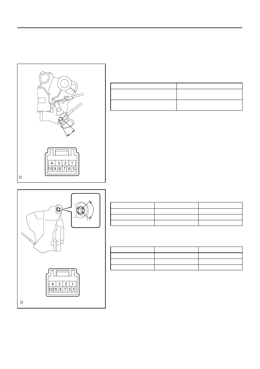
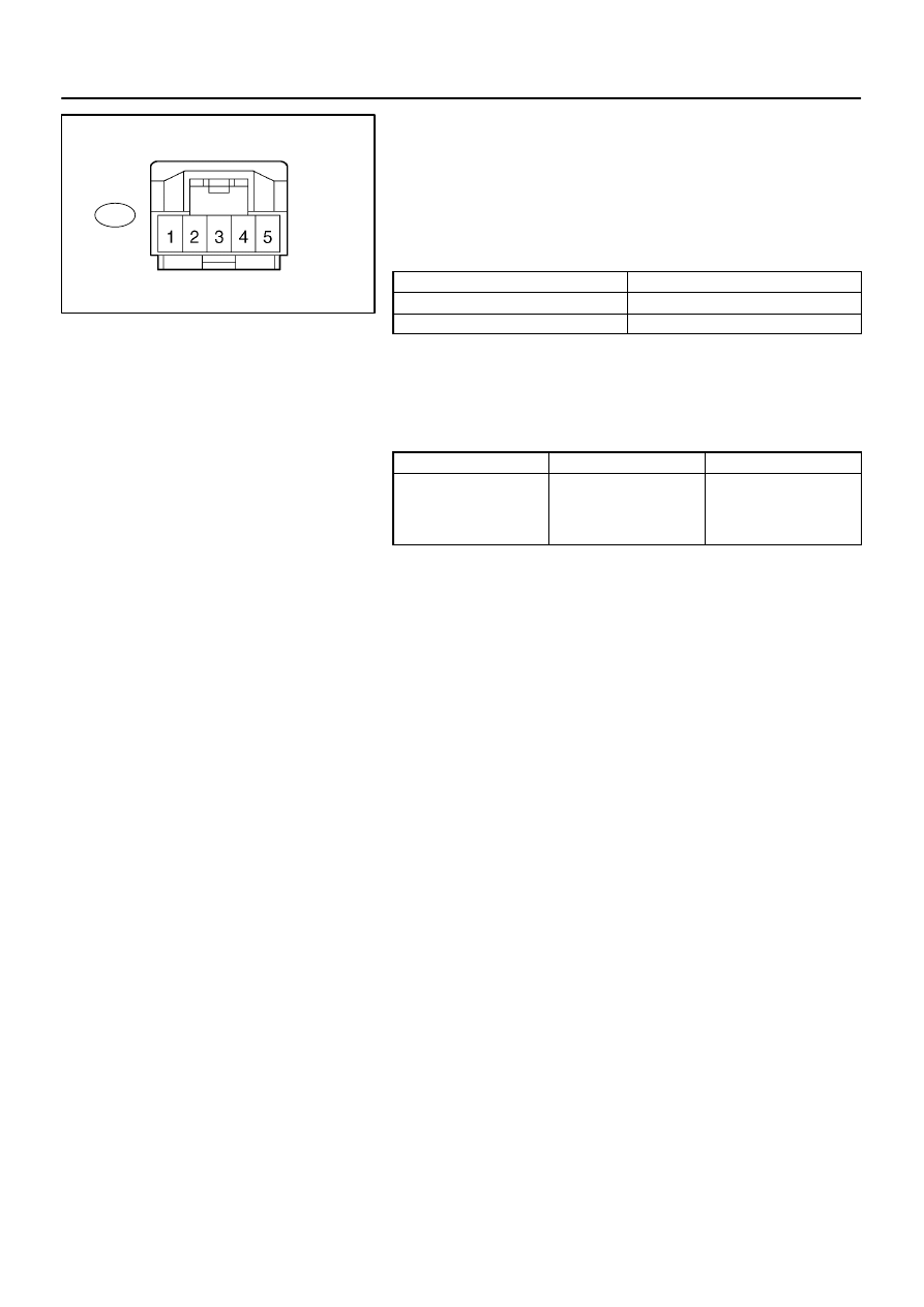
INSPECT DRIVER’S DOOR LOCK
(a)
Inspect the door lock motor operation.
Standard:
Measuring condition
Operation
Battery positive (+) Terminal – 4
Battery negative (–) Terminal – 1
Lock
Battery positive (+) Terminal – 1
Battery negative (–) Terminal – 4
Unlock
If the result is not as specified, replace the door lock assembly.
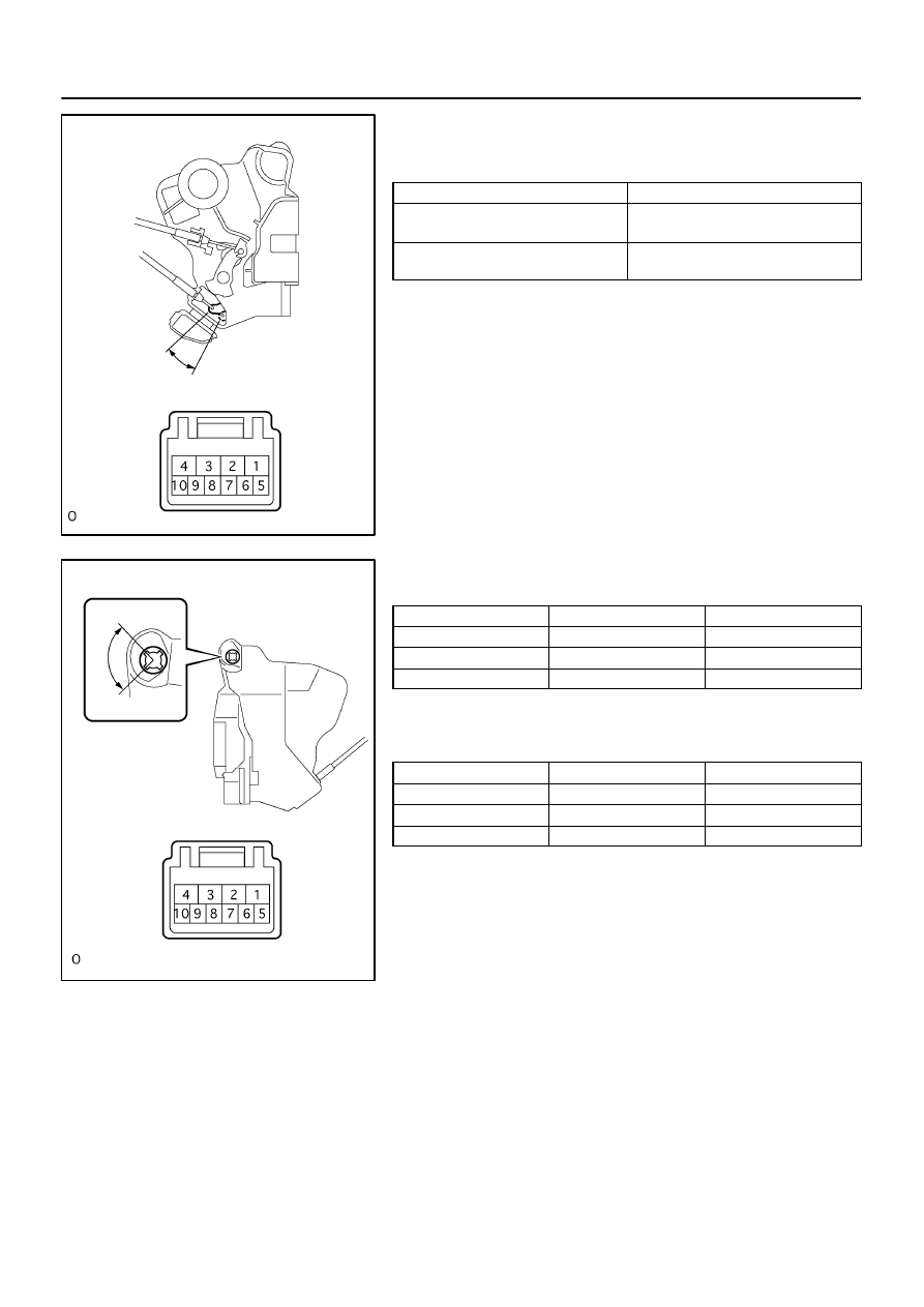
(b)
Inspect the door lock and unlock switch continuity.
Standard:
Door lock position
Terminal No.
Specified condition
Lock
7
⇔
9
Continuity
OFF
–
–
Unlock
7
⇔
10
Continuity
If the result is not as specified, replace the door lock assembly.
(c)
Inspect the position switch continuity.
Standard:
Door lock position
Terminal No.
Specified condition
Lock
7
⇔
8
No continuity
OFF
–
–
Unlock
7
⇔
8
Continuity
If the result is not as specified, replace the door lock assembly.
B59885
UNLOCK
LOCK
B56795
UNLOCK
LOCK
73–4
–
THEFT DETERRENT & DOOR LOCK
POWER DOOR LOCK CONTROL SYSTEM
1796
Author:
Date:
2004 COROLLA (RM1037U)
2.
INSPECT PASSENGER’S DOOR LOCK
(a)
Inspect the door lock motor operation.
Standard:
Measuring condition
Operation
Battery positive (+) Terminal – 4
Battery negative (–) Terminal – 1
Lock
Battery positive (+) Terminal – 1
Battery negative (–) Terminal – 4
Unlock
If the result is not as specified, replace the door lock assembly.
(b)
Inspect the door lock and unlock switch continuity.
Standard:
Door lock position
Terminal No.
Specified condition
Lock
6
⇔
8
Continuity
OFF
–
–
Unlock
5
⇔
8
Continuity
If the result is not as specified, replace the door lock assembly.
(c)
Inspect the position switch continuity.
Standard:
Door lock position
Terminal No.
Specified condition
Lock
7
⇔
8
No continuity
OFF
–
–
Unlock
7
⇔
8
Continuity
If the result is not as specified, replace the door lock assembly.
B56800
UNLOCK
LOCK
B56799
UNLOCK
LOCK
–
THEFT DETERRENT & DOOR LOCK
POWER DOOR LOCK CONTROL SYSTEM
73–5
1797
Author:
Date:
2004 COROLLA (RM1037U)
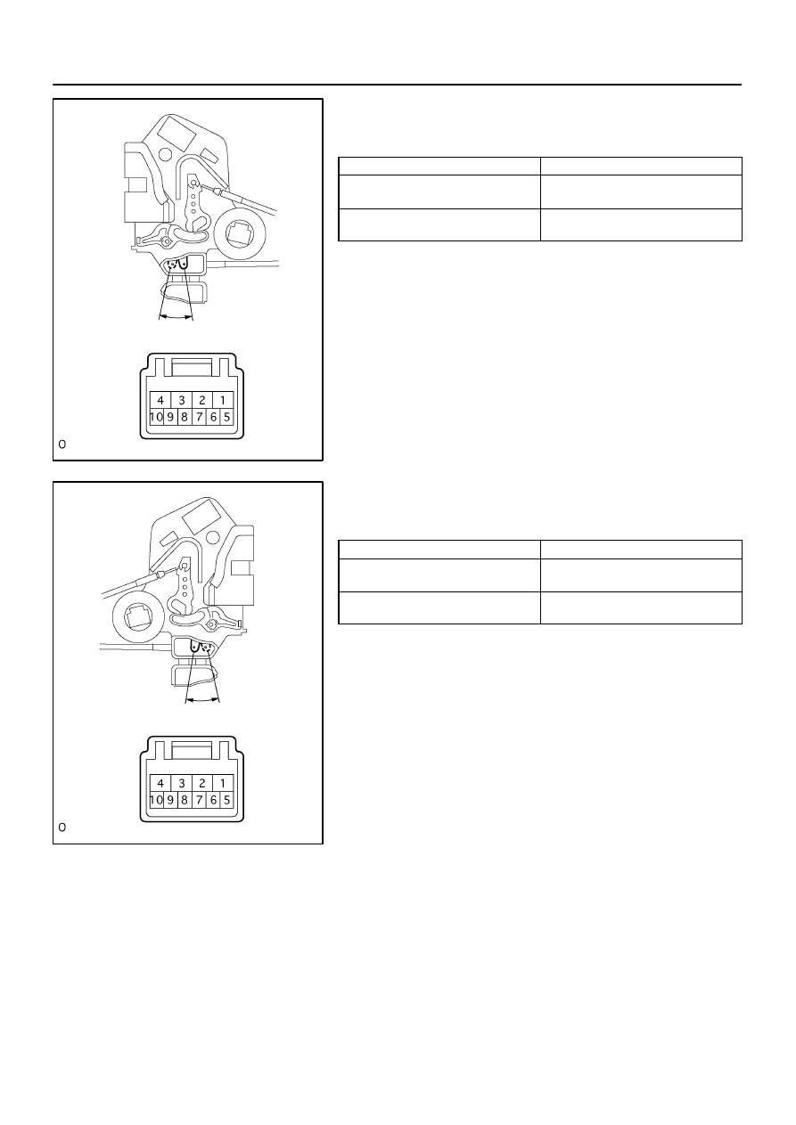
3.
INSPECT REAR DOOR LOCK LH
(a)
Inspect the door lock motor operation.
Standard:
Measuring condition
Operation
Battery positive (+) Terminal – 4
Battery negative (–) Terminal – 1
Lock
Battery positive (+) Terminal – 1
Battery negative (–) Terminal – 4
Unlock
If the result is not as specified, replace the door lock assembly.
4.
INSPECT REAR DOOR LOCK RH
(a)
Inspect the door lock motor operation.
Standard:
Measuring condition
Operation
Battery positive (+) Terminal – 4
Battery negative (–) Terminal – 1
Lock
Battery positive (+) Terminal – 1
Battery negative (–) Terminal – 4
Unlock
If the result is not as specified, replace the door lock assembly.
B59539
w/ Power Window
Door Lock
Control Switch
LOCK
UNLOCK
B59538
w/o Power Window
No pin (1 and 2)
No pin (4)
LOCK
UNLOCK
B59538
Passenger’s Side Switch
No pin (1 and 2)
No pin (4)
LOCK
UNLOCK
73–6
–
THEFT DETERRENT & DOOR LOCK
POWER DOOR LOCK CONTROL SYSTEM
1798
Author:
Date:
2004 COROLLA (RM1037U)
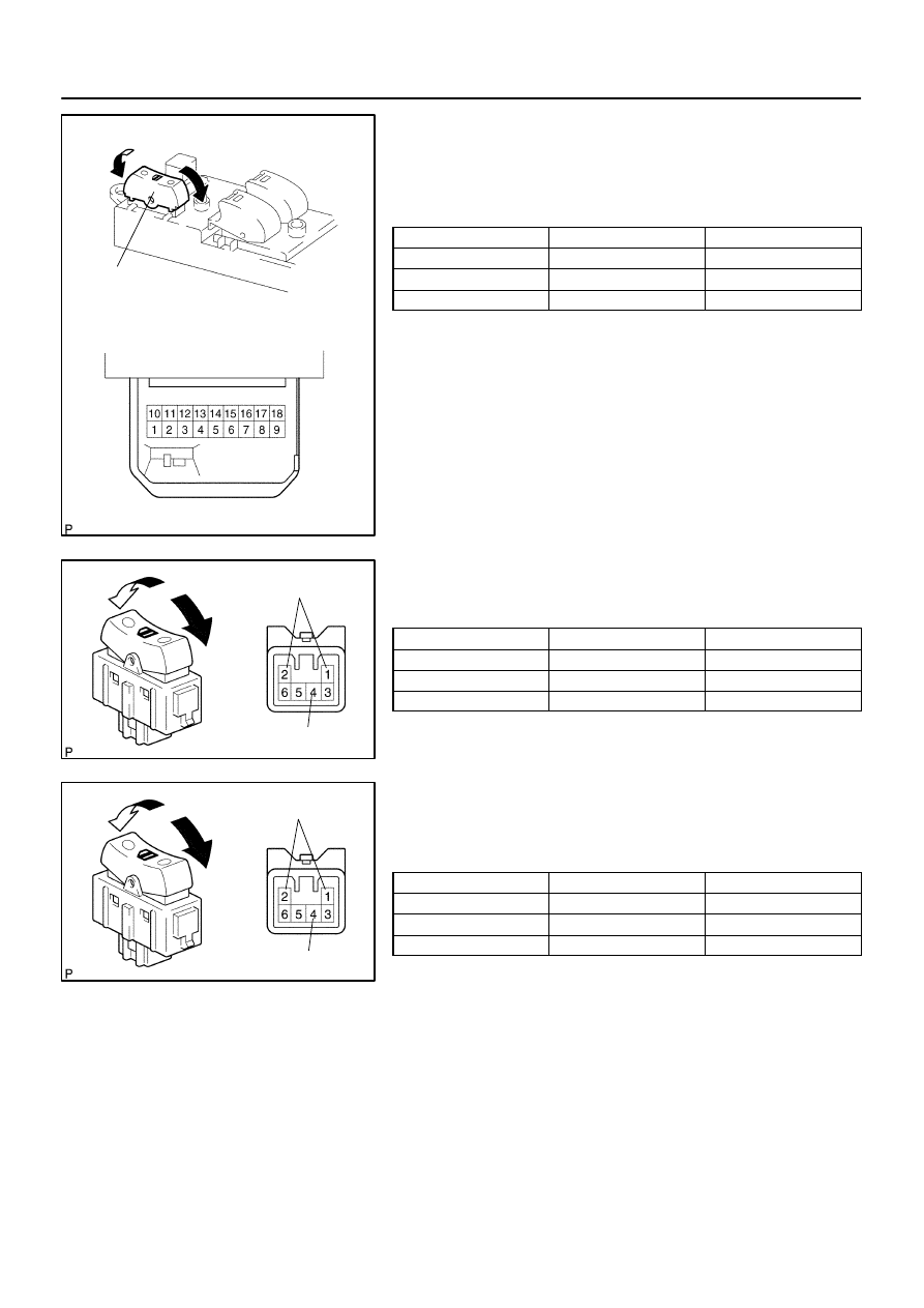
5.
INSPECT POWER WINDOW REGULATOR MASTER
SWITCH ASSY
(a)
w/ Power window:
Inspect the door lock control switch
continuity.
Standard:
Switch position
Terminal No.
Specified condition
Lock
1
⇔
3
⇔
5
Continuity
OFF
–
No continuity
Unlock
1
⇔
3
⇔
8
Continuity
If the result is not as specified, replace the switch.
(b)
w/o Power window:
Inspect the door lock control switch
continuity.
Standard:
Switch position
Terminal No.
Specified condition
Lock
3
⇔
6
Continuity
OFF
–
No continuity
Unlock
3
⇔
5
Continuity
If the result is not as specified, replace the switch.
6.
INSPECT DOOR CONTROL SWITCH ASSY
(a)
Passenger ’s side switch:
Inspect the door lock control switch
continuity.
Standard:
Switch position
Tester connection
Specified condition
Lock
3
⇔
6
Continuity
OFF
–
No continuity
Unlock
3
⇔
5
Continuity
If the result is not as specified, replace the switch.

730B0–02
–
THEFT DETERRENT & DOOR LOCK
WIRELESS DOOR LOCK CONTROL SYSTEM
73–7
1799
Author:
Date:
2004 COROLLA (RM1037U)
WIRELESS DOOR LOCK CONTROL SYSTEM
PRECAUTION
1.
NOTICES WHEN CHECKING
(a)
Power door LOCK/UNLOCK function:
The wireless remote control function operates only when the following 3 conditions are met.
(1)
No key is inserted into the ignition key cylinder.
(2)
All the doors are closed. However, doors can be unlocked even when any of the doors is opened.
(3)
The power door lock system operates normally.
HINT:
The UNLOCK function operates even when a door is open.
The UNLOCK function operates even when the key is inserted into the ignition key cylinder, however
it must be in the OFF position.
(b)
Remote panic function:
The wireless remote control function operates only when the following condition is met.
(1)
The ignition switch is OFF.
HINT:
The key can be inserted, however it must be in the OFF position.
(c)
The wireless door lock remote control operational area differs depending on the situation.
(1)
The operational area differs depending on the operators and the ways the transmitter is held.
(2)
In certain areas, the remote control function will only operate partially for the operational area
will be reduced due to the vehicle body shape and the influence of the surrounding environment.
(3)
Since the transmitter uses faint electric waves, strong electric waves or noise in the frequency
used may reduce the operational area or the remote control may not function.
(4)
When the battery weakens, the operational area is reduced or the remote control may not func-
tion.
HINT:
If the door control transmitter has been left in a place that is exposed to direct sunlight, such as on the instru-
ment panel, it may cause the battery to weaken or cause other such problems.

730B1–02
73–8
–
THEFT DETERRENT & DOOR LOCK
WIRELESS DOOR LOCK CONTROL SYSTEM
1800
Author:
Date:
2004 COROLLA (RM1037U)
ON–VEHICLE INSPECTION
1.
INSPECT WIRELESS DOOR LOCK CONTROL FUNCTIONS
HINT:
The switch described in this text is a switch for transmitting signals (LOCK switch, UNLOCK switch
and PANIC switch) which is built into the door control transmitter.
All the functions listed below must be checked in the remote control operational area.
(a)
Put the vehicle under the conditions that allow the wireless control function to be operated (See PRE-
CAUTION on page
73–7
).
(b)
Check the basic function.
(1)
Check that all the doors lock when the LOCK switch is pressed.
(2)
Check that only the driver side door unlocks when the UNLOCK switch is pressed once and the
other doors unlock when the UNLOCK switch is pressed again within 3 seconds.
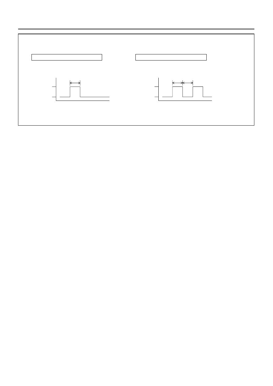
(c)
Check the chattering prevention function.
(1)
Check that the corresponding operation occurs only once and is not repeated continuously while
the switch is held. However, when the switch is operated repeatedly at 1 second intervals, check
that the corresponding operation is carried out.
(d)
Check the automatic lock function.
(1)
Check that all the doors lock automatically as long as none of them have been opened or all the
doors have not been locked within approx. 30 seconds after they are unlocked by pressing the
UNLOCK switch.
(2)
Check that the automatic locking function does not operate when any door has been opened or
all of them have been locked within approx. 30 seconds after they are unlocked by pressing the
UNLOCK switch.
(e)
Check the switch operation fail–safe function.
(1)
Check that the doors can not be locked using the switch while the key is in the ignition key cylin-
der. However, this does not apply when the system is in the recognition code registration mode.
(f)
Check the operation stop function when a door is open or not completely closed.
(1)
Check that the doors are not locked by the switch while any door is open or not completely closed.
However, the glass hatch open operation is possible in this situation.
(g)
Check the repeat function.
(1)
Check that all the doors attempt to automatically lock once again 1 second after the LOCK switch
has been pressed while the movement of the driver side door control knob is being restricted
while in the unlocked position.
(h)
Check the hazard warning lamps flashing functions (answer–back).
(1)
When the LOCK switch is pressed, check that the lamps flash once with the locking of all the
doors.
(2)
When the UNLOCK switch is pressed once, check that the lamps flash twice with the unlocking
of the driver side door.
(3)
When the UNLOCK switch is pressed again within 3 seconds, check that the lamps flash twice
with the unlocking of all the doors.
(i)
Check the remote panic alarm function.
(1)
Check that the horn sounds, and the headlamps, the taillamps and the hazard warning lamps
flash for 60 seconds by the theft alarm function when the PANIC switch is pressed. Also, check
that the horn stops sounding and the lamps stop flashing when either switch of the transmitter
is pressed once again.
(j)
Check the illuminated entry function.
(1)
When all the doors are locked, pressing the UNLOCK switch causes the room lamp (when the
lamp switch is in the DOOR position) to illuminate simultaneously with the unlock operation.
(2)
Check that the room lamp goes off in approx. 15 seconds if doors have not been opened.
B59092
Door Control Receiver
(Wire Harness Side)
D3
–
THEFT DETERRENT & DOOR LOCK
WIRELESS DOOR LOCK CONTROL SYSTEM
73–9
1801
Author:
Date:
2004 COROLLA (RM1037U)
2.
CHECK DOOR CONTROL RECEIVER
(a)
Disconnect the D3 connector from the door control receiv-
er.
(b)
Check the continuity and voltage between the terminals
of the door control receiver connector and the body
ground, as shown in the illustration and table.
Standard:
Symbols (Terminal No.)
Specified condition
+B (D3– 5) – Body ground
10 – 14 V
GND (D3–1) – Body ground
Continuity
If the result is not as specified, there may be a malfunction on
the wire harness side.
(c)
Reconnect the connector and check the voltage between
the terminal and body ground.
Standard:
Symbols (Terminal No.)
Condition
Specified Condition
RDA (D3–2) –
Body ground
No key in ignition key
cylinder, all doors closed
and each transmitter
switch OFF
→
ON
1 V or less
→
Approx. 6 – 7 V
→
1 V or less
If the result is not as specified, the receiver may have a malfunc-
tion.
730B2–01
B59380
Tape
B59371
73–10
–
THEFT DETERRENT & DOOR LOCK
TRANSMITTER BATTERY
1802
Author:
Date:
2004 COROLLA (RM1037U)
TRANSMITTER BATTERY
REPLACEMENT
1.
REPLACE TRANSMITTER BATTERY
NOTICE:
Special caution should be taken for handling each component as they are precision electronic com-
ponents.
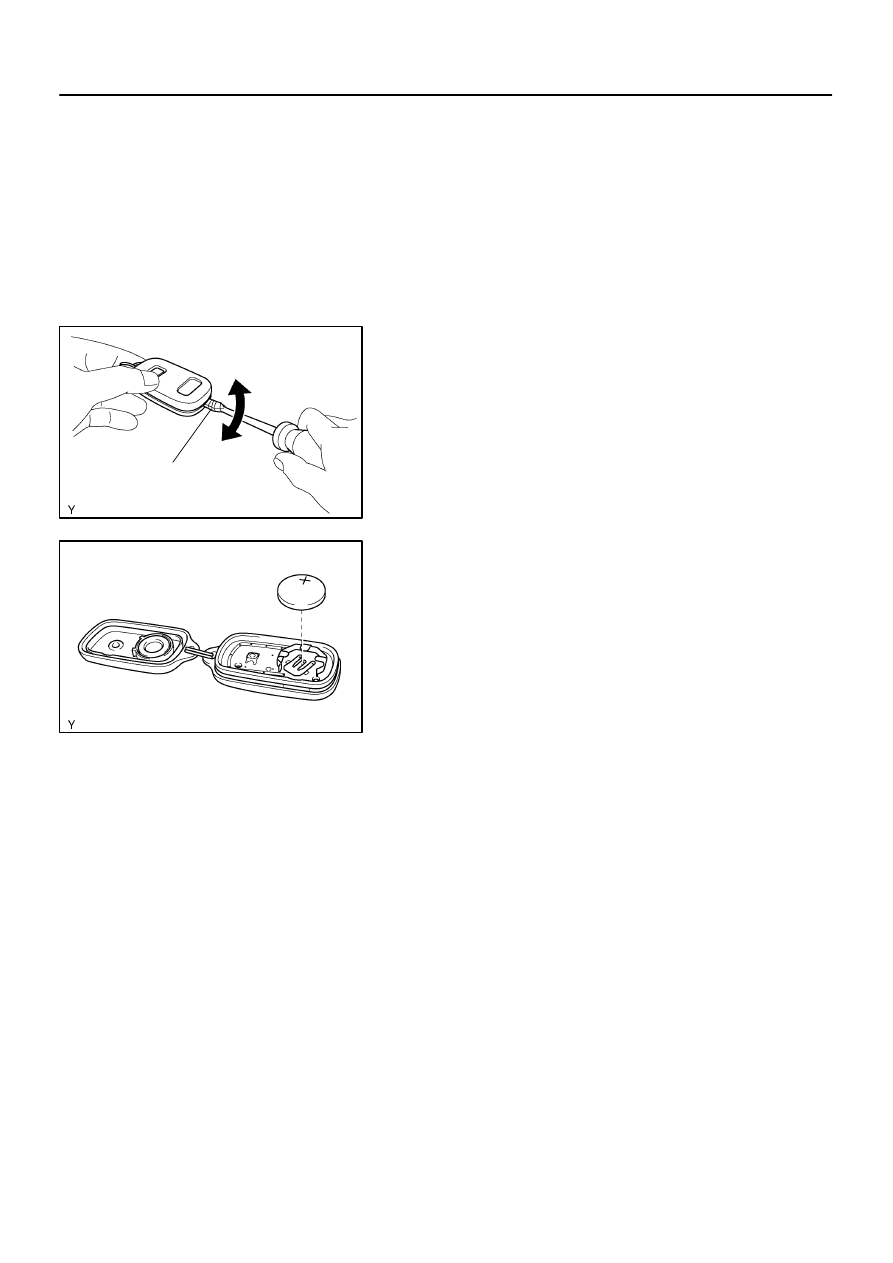
(a)
Using a screwdriver, pry out the transmitter case.
NOTICE:
Do not forcibly pry out the case.
HINT:
Tape the screwdriver tip before use.
(b)
Remove the battery (lithium battery).
NOTICE:
Do not push the terminals with your finger.
Prying up the battery (lithium battery) to forcibly re-
move it will cause deformation of the terminals.
Do not touch the battery with wet hands. Water may
cause unexpected rust.
Do not touch or move any components inside the
transmitter as it may interfere with proper operation.
2.
INSTALL TRANSMITTER BATTERY
(a)
Install a new battery (lithium battery) with the positive (+)
side up, as shown in the illustration.
NOTICE:
Be sure that the positive side and the negative side of
the transmitter battery are matched–up correctly.
Be careful not to bend the electrode of the transmitter
battery insertion.
Be careful that dust or oil does not adhere to the trans-
mitter case.
(b)
Install the case securely.
730B3–03
B58899
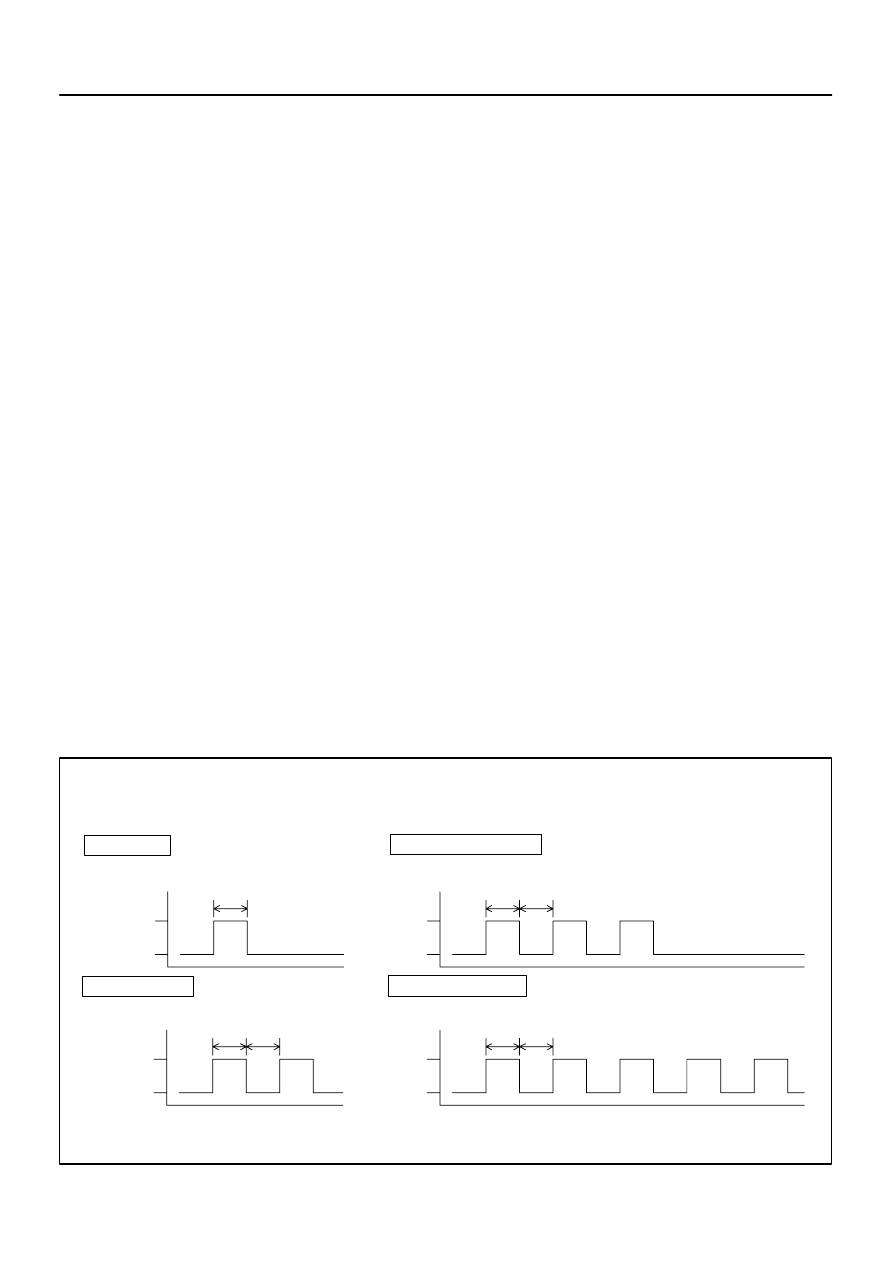
ON–LOCK operation: 1 time
Add Mode
Rewrite Mode
ON–LOCK operation: 2 times
Confirmation Mode
ON–LOCK operation: 3 times
Prohibition Mode
ON–LOCK operation: 5 times
T1
ON
LOCK
ON
LOCK
ON
LOCK
ON
LOCK
T1
T1
T1
T1
T1
T1
T1: Approx. 1 sec.
Number of ON–LOCK operation of ignition switch:
–
THEFT DETERRENT & DOOR LOCK
DOOR CONTROL TRANSMITTER
73–11
1803
Author:
Date:
2004 COROLLA (RM1037U)
DOOR CONTROL TRANSMITTER
REGISTRATION
1.
REGISTRATION OF RECOGNITION CODE
HINT:
The add mode is used to retain the already registered codes while registering a new recognition code.
This mode is used when adding a transmitter. If the number of the registered codes exceeds 4, the
previously registered code will be correspondingly erased in order, starting from the first registered
code.
The rewrite mode is used to erase all the previously registered codes and register only new recognition
codes. This mode is used when exchanging the transmitter or the door control receiver for new one.
The prohibition mode is used to erase all the registered codes and cancel the wireless door lock func-
tion. Use this mode when the transmitter is lost.
The confirmation mode is to confirm how many recognition codes have already been registered before
an additional registration of a recognition code.
All the following registration procedures must be performed in order continuously.
(a)
The vehicle should be in the following conditions.
(1)
The key is not inserted in the ignition key cylinder.
(2)
Driver’s door is OPENED. (The other doors are CLOSED)
(3)
Driver’s door is UNLOCKED.
(b)
Perform the following operations to select the desired mode.
(1)
Insert and remove the key from the ignition switch twice within 5 seconds.
(2)
After the above operations, close and open the driver door twice within 40 seconds. Then insert
the key into the ignition key cylinder and remove it.
(3)
After the above operations, close and open the driver door twice within 40 seconds. Then insert
the key into the ignition key cylinder and close the door.
(4)
Turn the ignition switch from LOCK to ON and back to LOCK at approximately 1 second interval
1 to 5 times to select a mode (see the table below). Then remove the key from the ignition key
cylinder.
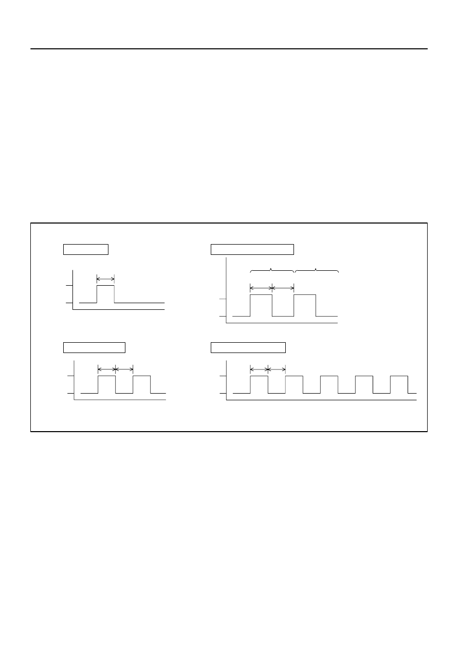
B50827
Confirmation Mode
Add Mode
Prohibition Mode
Rewrite Mode
LOCK
LOCK
LOCK
LOCK
UNLOCK
UNLOCK
UNLOCK
UNLOCK
1st time
2nd time
T1
T1: Approx. 1 sec.
T2: Approx. 2 sec.
T1
T1
T1
T1
T2
T2
Response of selected mode (Power door lock operation):
73–12
–
THEFT DETERRENT & DOOR LOCK
DOOR CONTROL TRANSMITTER
1804
Author:
Date:
2004 COROLLA (RM1037U)
NOTICE:
If the number of the ON–LOCK operation of the ignition switch is 0, 4 or 6 or more, there will be no
response (power door lock and unlock operation) to inform which mode has been selected.
(5)
After selecting a mode, the integration relay automatically performs the power door
LOCK–UNLOCK operation within 3 seconds to inform the selected mode (see the table below).
HINT:
In the confirmation mode, when the operation is performed twice, it directs that 2 types of recognition
codes have been registered.
In the confirmation mode, If the number of the registration code is 0, the LOCK–UNLOCK operation
is automatically performed 5 times.
If the prohibition mode or confirmation mode is selected, registration procedure is completed.
(c)
Register the new recognition codes (Add mode or Rewrite mode):
(1)
Within 40 seconds after the add mode or the rewrite mode has been selected, press the LOCK
and UNLOCK switches on the transmitter switch simultaneously for 1.0 – 1.5 seconds.
Within 3 seconds after the previous operation, press either one of the switches for more than 1.0
seconds.
(2)
Within 3 seconds after the transmitter switch has been turned OFF, the LOCK–UNLOCK opera-
tion will be automatically performed once if the registration of the recognition code of the transmit-
ter is completed correctly.
In case the LOCK–UNLOCK operation is performed twice, the registra-
tion of recognition code has failed. Perform the registration procedure from the beginning once
again.
B58900
LOCK–UNLOCK Occurs Once
LOCK–UNLOCK Occurs Twice
Registration of recognition code has
been completed.
Registration of recognition code has failed.
LOCK
LOCK
UNLOCK
UNLOCK
Response for registration completion:
T1: Approx. 1 sec.
T1
T1
T1
–
THEFT DETERRENT & DOOR LOCK
DOOR CONTROL TRANSMITTER
73–13
1805
Author:
Date:
2004 COROLLA (RM1037U)
(3)
If the multiple transmitter to be registered, repeat step (c) within 40 seconds after the previous
registration.
HINT:
4 types of recognition codes can be registered at one time.
If even one of the following conditions is satisfied, the registration mode will finish.
40 seconds have elapsed while an input of each mode is ready.
Any of the doors is opened
The key plate is inserted in the ignition key cylinder.
4 types of recognition codes are registered at once.

730AV–01
Alarming method
Alarming time
Headlight
Hazard Warning Light
Room Light
Sounding at a cycle of approx. 0.4 sec.
Illuminating (turn on)
Approx. 60 sec.
Flashing at a cycle of flasher relay
Flashing at a cycle of approx. 0.4 sec.
Vehicle Horn
73–14
–
THEFT DETERRENT & DOOR LOCK
TOYOTA VEHICLE INTRUSION PROTECTION
SYSTEM
1806
Author:
Date:
2004 COROLLA (RM1037U)
TOYOTA VEHICLE INTRUSION PROTECTION SYSTEM
ON–VEHICLE INSPECTION
1.
OUTLINE OF TOYOTA VEHICLE INTRUSION PROTECTION (TVIP) SYSTEM
HINT:
The theft deterrent system has 2 modes; one is the active mode that is an initially set mode and another is
the passive mode that can be switched ON/OFF by the specified method (See step 4).
(a)
When the theft deterrent system detects any theft, the system will sound the horns and flash the lights
to alert the people around the vehicle to the theft.
HINT:
Each mode (active and passive) has 4 states; disarmed state, arming preparation state, armed state, alarm
sounding state.
(1)
Disarmed state:
The user is near the vehicle.
The alarming function does not operate.
The theft deterrent function does not operate.
(2)
Arming preparation state:
Time from the user locks a door to leave the vehicle.
Time for transferring to the armed state.
The theft deterrent function does not operate.
(3)
Armed state:
The user leaves the vehicle completely.
The theft deterrent function operates.
(4)
Alarm sounding state:
Once a theft is detected in the armed state, the system will sound the horns and flash the lights
to alert the people around the vehicle to the theft.
Refer to the table for the alarming method and time.
HINT:
In the alarm sounding state, when either of the front doors is unlocked and no key is inserted in the ignition
key cylinder, forced door lock signal is output.
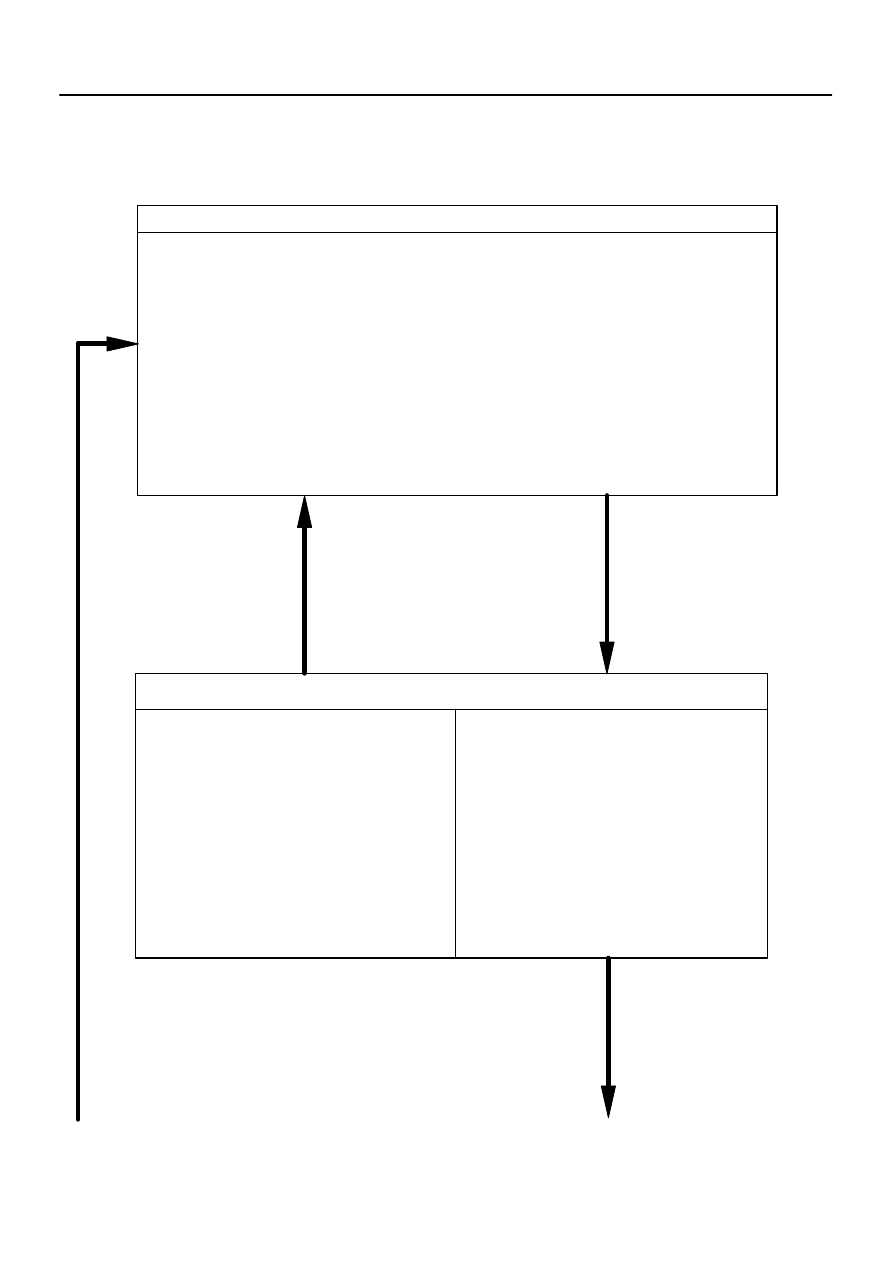
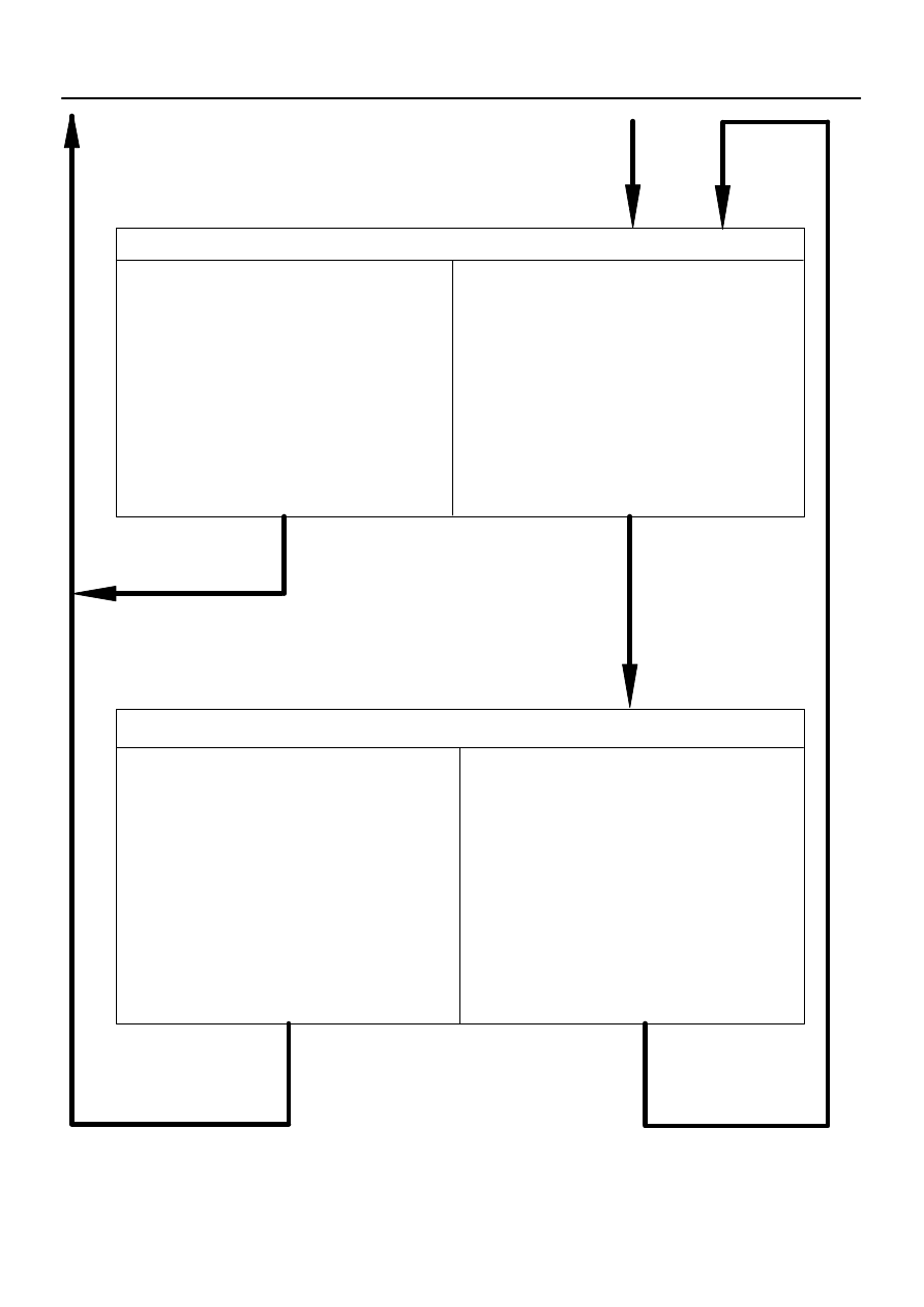
Disarmed State
Arming Preparation State
Perform the following and the system will
go to ”Armed state”:
Allow 30 seconds to elapse with all doors
and luggage compartment door closed and
locked.
Perform any of the followings and the system
will return to ”Disarmed state”:
Open either of the closed doors or luggage
compartment door.
Unlock either of the locked front doors.
Insert the key in the ignition key cylinder.
Disconnect the battery once, and then
reconnect it.
(No key inserted in ignition key cylinder)
Perform any of the followings and the system will go to ”Arming preparation state”:
With all doors and luggage compartment door closed, lock all doors with key.
With all doors and luggage compartment door closed, lock all doors by the wireless door
lock operation.
With all doors and luggage compartment door closed, open and close either of doors or
luggage compartment door, and then close and lock all doors and luggage compartment
door.
Continued from next page
Continued to next page
–
THEFT DETERRENT & DOOR LOCK
TOYOTA VEHICLE INTRUSION PROTECTION
SYSTEM
73–15
1807
Author:
Date:
2004 COROLLA (RM1037U)
2.
ACTIVE ARMING MODE
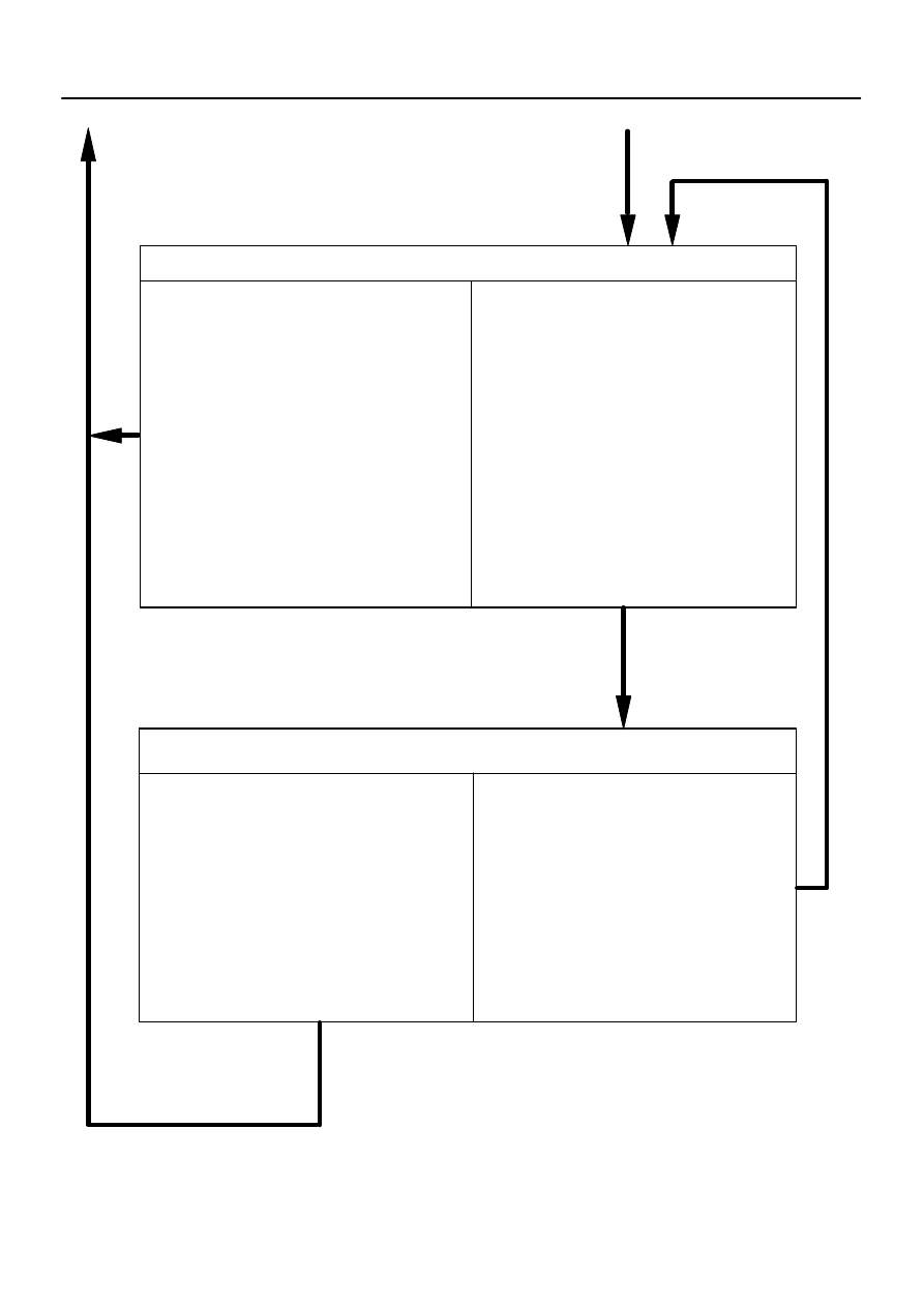
Armed State
Perform any of the followings and the system
will return to ”Disarmed state”:
Unlock the locked doors by the wireless door
lock operation.
Unlock the locked doors with key (except the
luggage compartment door).
Insert the key into the ignition key cylinder
and turn the ignition ON.
Perform any of the followings and the system
will go to ”Alarm sounding state”:
Open either of the closed doors.
Unlock either of the locked front doors in any
way other than the key and the wireless door
lock operations.
Open the closed luggage compartment
door.
Reconnect the battery terminal.
Turn the ignition switch ON without using the
key.
Theft is detected by the glass breakage
sensor.
Alarm Sounding State
Once a theft is detected, lights will flash and
horns will sound to alert people around the
vehicle to the theft.
After the above specified alarming time (60
sec.) has elapsed, the system will return to
”Armed state”.
Perform any of the followings and the sys-
tem will return to ”Disarmed state”:
Unlock the locked doors by the wireless
door lock operation.
Unlock the locked doors with key (except
the luggage compartment door).
Insert the key into the ignition key cylinder
and turn the ignition ON.
Continued from previous page
Continued to previous page
73–16
–
THEFT DETERRENT & DOOR LOCK
TOYOTA VEHICLE INTRUSION PROTECTION
SYSTEM
1808
Author:
Date:
2004 COROLLA (RM1037U)

–
THEFT DETERRENT & DOOR LOCK
TOYOTA VEHICLE INTRUSION PROTECTION
SYSTEM
73–17
1809
Author:
Date:
2004 COROLLA (RM1037U)
Indicator light output:
Condition
Indicator light
Disarmed state
OFF
Arming preparation state
ON
Armed state
BLINK
Alarm sounding state
ON
HINT:
Blinking frequency:
0.2 seconds (ON)
1.8 seconds (OFF)
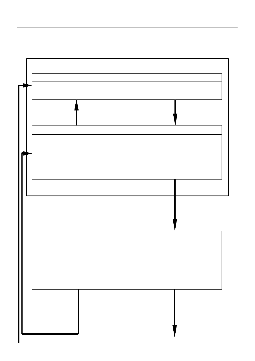
Disarmed State (A)
Perform any of the followings and the system
will return to ”Disarmed state (A)”:
Push the unlock switch on the transmitter.
Put the key in the lock cylinder on the driver’s
or passenger’s door and turn it towards unlock.
Insert the key in the ignition key cylinder.
Reconnect the battery terminal.
Disarmed State (B)
Perform the following and the system will go to
”Arming preparation state”:
Close all doors and luggage compartment
door.
Perform the following and the system will re-
turn to ”Disarmed state (B)”:
Open either of the closed doors or luggage
compartment door.
Arming Preparation State
Perform the following and the system will go to
”Armed state”:
Allow 30 seconds to elapse with all doors and
luggage compartment door closed.
Perform the following and the system will go to ”Disarmed state (B)”:
Insert and remove the key from the ignition key cylinder, and then open and close the driver’s door.
Continued from next page
Continued to next page
73–18
–
THEFT DETERRENT & DOOR LOCK
TOYOTA VEHICLE INTRUSION PROTECTION
SYSTEM
1810
Author:
Date:
2004 COROLLA (RM1037U)
3.
PASSIVE ARMING MODE
This mode can be switched according to the specified method (See step 4).
Initially set mode (when shipped from factory) is the active mode (No passive mode).
Perform the following and the system will return
to ”Armed state”:
The alarm sounding time (60 sec.) has
elapsed.
Alarm Sounding State
Perform any of the followings and the system
will return to ”Disarmed state (A)”:
Push the unlock switch on the transmitter.
Put the key in the lock cylinder on the driver’s
or passenger’s door and turn it towards
unlock.
Insert the key into the ignition key cylinder
and turn the ignition ON.
Perform any of the followings and the system
will return to ”Disarmed state (A)”:
Push the unlock switch on the transmitter.
Put the key in the lock cylinder on the driver’s
or passenger’s door and turn it towards
unlock.
Insert the key into the ignition key cylinder
and turn the ignition ON.
Armed State
Perform any of the followings and the system will
go to ”Alarm sounding state”:
Open either of the closed doors and allow the
entry delay time*
1
to pass.
Open the closed luggage compartment door.
Reconnect the battery terminal.
Turn the ignition ON without using the key.
*
1
: See the ”Entry delay function”
on the next page
Continued from previous page
Continued to previous page
–
THEFT DETERRENT & DOOR LOCK
TOYOTA VEHICLE INTRUSION PROTECTION
SYSTEM
73–19
1811
Author:
Date:
2004 COROLLA (RM1037U)
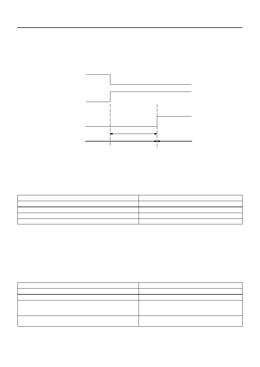
Door
Indicator
Alarming output
System condition
Armed state
Alarm sounding
state
Entry delay time
(0, 14, 30 sec.)
Close
Open
ON
OFF
ON
OFF
73–20
–
THEFT DETERRENT & DOOR LOCK
TOYOTA VEHICLE INTRUSION PROTECTION
SYSTEM
1812
Author:
Date:
2004 COROLLA (RM1037U)
Entry delay function:
HINT:
In the armed state, if either closed door is opened, entry delay time will start.
If the transferring condition (Armed state
→
Disarmed state) is satisfied during this entry delay time, the sys-
tem will transfer to the disarmed state. However if the condition is not satisfied, the system will judge it to
be a theft, and then the system will transfer to the alarm sounding state.
HINT:
The entry delay time can be selected among 0, 14, 30 seconds by the customizing function.
Indicator light output:
Condition
Indicator light
Disarmed state
OFF
Arming preparation state
ON
Armed state (Entry delay time)
BLINK (ON)
Alarm sounding state
ON
HINT:
Blinking frequency:
0.2 seconds (ON)
1.8 seconds (OFF)
Transfer to the active mode:
HINT:
In each state of the passive mode, when the transferring condition to the active mode (disarmed state of
active mode
→
arming preparation state of active mode) is satisfied, the system will transfer to each state
of the active mode. In this case, the active mode will continue until the system transfers to the disarmed state.
State of Passive Mode Before Transfer
State of Active Mode After Transfer
Disarmed state
Arming preparation state
Arming preparation state
Arming preparation state (continuing for 30 sec.)
Armed state (During entry delay time)
Armed state
(After alarming time has elapsed, the system will transfer to the
armed state)
Alarm sounding state
After alarming time has elapsed, the system will transfer to the
armed state
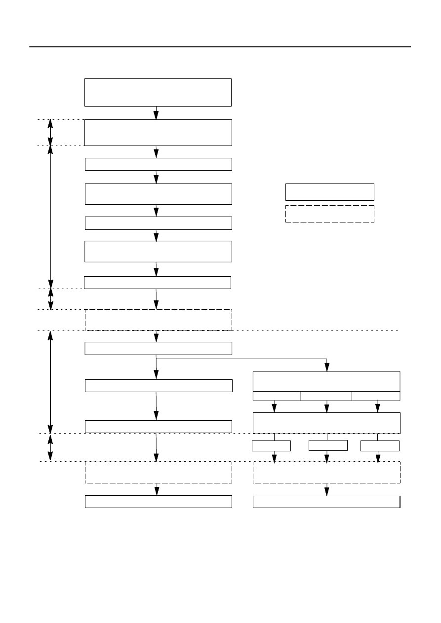
Insert and remove the key from the ignition
key cylinder 3 times.
Lock and unlock all doors 3 times by the key
or remote control.
Lock and unlock the driver’s door lock knob
3 times.
Open and close the driver’s door.
The system starts forced door lock once
(answer back).
Unlock the driver’s door lock knob.
Close and open the driver’s door 2 times
Lock and unlock the driver’s door lock knob.
PASSIVE MODE OFF
Close and open the driver’s door 3 to 5
times
Lock and unlock the driver’s door lock
knob.
PASSIVE MODE ON
Within
40 sec.
Within
20 sec.
HINT:
Initial mode is PASSIVE MODE OFF.
If there is a different signal in the middle of changing, it is invalid.
*: Entry delay time
Input to the vehicle
Output from the vehicle
* 0 sec.
4 times
5 times
3 times
* 14 sec.
* 30 sec.
2 sec.
Open the driver’s door.
Close the driver’s door.
Within
5 sec.
No key in the ignition key cylinder
Driver’s door opened
All doors unlocked
2 sec.
The system starts forced door lock once
(answer back).
The system starts forced door lock once
(answer back).
( = Vehicle initial condition)
–
THEFT DETERRENT & DOOR LOCK
TOYOTA VEHICLE INTRUSION PROTECTION
SYSTEM
73–21
1813
Author:
Date:
2004 COROLLA (RM1037U)
4.
CHANGING METHOD OF PASSIVE MODE
(ON or OFF)
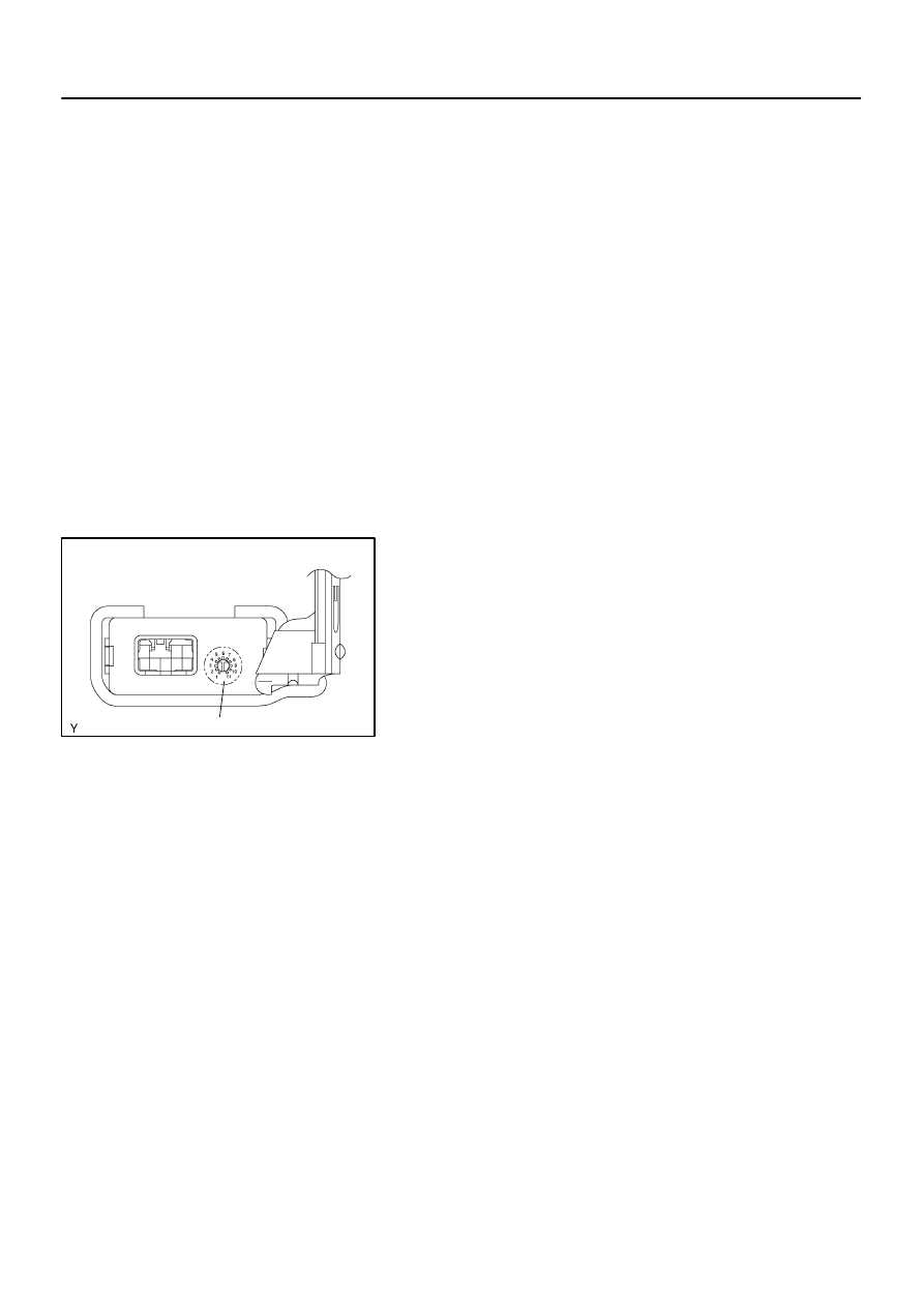
B59188
Glass Breakage Sensor ECU
Volume
73–22
–
THEFT DETERRENT & DOOR LOCK
TOYOTA VEHICLE INTRUSION PROTECTION
SYSTEM
1814
Author:
Date:
2004 COROLLA (RM1037U)
5.
FORCED DOOR LOCK CONTROL
(a)
Forced door lock is a control that prevents intrusion into vehicles. When a door is unlocked (when an
alarm starts), instantaneously forced door lock will be executed.
(1)
Condition to execute forced door lock:
Detecting any or all of the following conditions activates forced door lock.
Theft deterrent system is in the alarm sounding state of the active mode.
No key is in the ignition key cylinder.
Any of the front doors is unlocked.
Since the previous forced door lock, 0.38 seconds or more have elapsed.
(2)
Conditions to stop forced door lock:
Detecting any of the following conditions stops forced door lock.
All doors are locked.
The alarm has finished.
The key is inserted into the key cylinder.
6.
OPERATE GLASS BREAKAGE SENSOR
(a)
If the glass breakage sensor detects the glass is broken
(at 1st time), the sensor will issue an alarm for 20 seconds
(pre–alarming). If the glass breakage sensor detects the
glass is broken further more (at 2nd time), the sensor will
issue an alarm for 60 seconds.
(b)
The sensitivity of the glass breakage sensor can be ad-
justed by the volume switch in the glass breakage sensor
ECU.
HINT:
Because the glass breakage sensor has a high sensitivity, it
might issue a wrong alarm if it is adjusted in the volume of high
sensitive.
Wyszukiwarka
Podobne podstrony:
73 Anti Theft and Door Locks
73 Theft Deterrent and Door Lock
73 Theft Deterrent and Door Lock
M39t1 Remote Keyless Entry and Anti theft System
M39t2 Remote Keyless Entry and Anti theft System
diagnostics Anti Theft
American Woodworker Drawer And Door Pulls (2)
75 Engine Hood and Door
M39t3 Imobiliser Anti theft System
Anti Semitism and Islamophobia new enemies, old patterns
11701 LEBARON COUPE CHRYSLER 3 5 WIRE DOOR LOCKS ALERT SHELBY UNITS
REMOTE ENTRY & KEYLESS ANTI THEFT SYSTEM 9T 12
POWER DOOR LOCKS
12856 BOXSTER PORSCHE 1 WIRE DOOR LOCKS JBS UNITS
05 6 F01 Anti theft System
Anti theft Immobilizer On Board Diagnostic (OBD) inst vw
75 Engine Hood and Door
więcej podobnych podstron