HEEL
SAILING YACHT PERFORMANCE : THE EFFECTS OF
ANGLE AND LEEWAY ANGLE ON RESISTANCE AND SIDEFORCE
Sebnem Helvacioglu :
Faculty of Naval Architecture and Ocean Engineering, ITU
Mustafa Insel
: Faculty of Naval Architecture and Ocean Engineering, ITU
ABSTRACT
A racing yacht sails in perfect balance of aerodynamic, hydrodynamic and hydrostatic forces with a leeway angle
and a heel angle. The balance of forces and moments must be solved to obtain sailing leeway and heel angles and predict
the speed of the yacht. In this paper, an approach based on towing tank tests and aerodynamic sail data is presented to solve
this task.
An elementary background theory of aerodynamic and hydrodynamic forces and moments due to sail and the hull
is given to present the balance equations.
Aerodynamic forces are introduced by sail lift and drag coefficients.
Hydrodynamic forces are derived from towing tank tests for several heel and leeway angles by use of a dedicated
experimental system based on a six component balance dynamometer.
A PC based data acquisition system is utilised to
collect tank data. A typical sailing yacht model at l/8 scale is used for towing tank tests. Towing tank tests are analyzed
to investigate the effects of heel angle and leeway angle on the resistance and sideforce generated by the hull. And finally,
a VPP analysis is carried out to derive the performance curves.
NOMENCLATURE
: Constant
C
: Constant
CLR
: Centre of lateral resistance
COE
: Centre of effort
: Aerodynamic heeling force coefficient
: Skin friction coefficient
: Aerodynamic driving force coefficient
: Induced resistance coefficient
D
: Drag
: Aerodynamic heeling force
F
LAT
: Horizontal aerodynamic force
: Aerodynamic driving force
F N
: Froude number
: Hydrodynamic side force
F
S-HOR
: Hydrodynamic side force
: Vertical aerodynamic force
: Vertical hydrodynamic force
k
: Form coefficient
L
: Lift
LWL
: Load waterline
: Heeling moment
: Air trimming moment
M
: Water trimming moment
: Righting moment
: Water yawing moment
: Air yawing moment
R
: Hydrodynamic resistance
R A
: Righting arm
R e
: Reynolds number
: Frictional resistance
: Resistance due to heel
: Induced resistance
: Total resistance
: Viscous resistance
: Wave resistance
: Sail area
: Apparent wind speed
: Speed made good
: Boat speed
: True wind speed
W S A
: Wetted surface area
: Apparent wind angle
: Aerodynamic efficiency angle
: Hydrodynamic efficiency angle
A
: Displacement
: True wind angle
: Leeway or yaw angle
: Kinematic viscosity
: Mass density of air
: Angle of heel
INTRODUCTION
There has been recently some interest in sailing yacht racing in Turkey. A study of sailing
yacht performance in the design stage has been started Istanbul Technical University, and first stage
of this study is presented in this paper.
Performance prediction of sailing yachts is of a complex nature, and differs from
conventional ship performance prediction due to presence of leeway angle, hence the sideforce
associated with it.
The resistance and side force prediction of a yacht is a complicated
hydrodynamic problem because of asymmetrical flow about the hull. Experimental methods are
being utilised widely for performance predictions.
An experimental approach (Dayi 1991) has been developed to measure the resistance, side
force, yawing moment, heeling moment, sinkage and trim angle of a yacht sailing in fixed heel angle
and leeway angle at a certain speed in ITU., Ata Nutku Ship Model Testing Laboratory (ANSMTL).
The approach has been verified by experiments on a sailing yacht model at l/8 scale with five
different keels. The variation of total resistance and sideforce have been investigated by changing
the heel angle, leeway angle, speed and keel characteristics. Hydrodynamic efficiency of the hull
(sideforce/resistance) is demonstrated.
Based on aerodynamic data and towing tank data, a velocity prediction program has been
developed to predict the yacht speed at any arbitrary true wind angle and true wind speed
(Helvacioglu and Insel 1994).
THE BALANCE OF AERODYNAMIC AND HYDRODYNAMIC FORCES
The aerodynamic forces acting on a sail and hydrodynamic-hydrostatic forces acting on a hull
must be
balanced for a sailing yacht. The forces and their relative positions, hence the moments,
are given in Figure 1. Aerodynamic forces are generated by the wind with a true wind speed
at a true wind angle of
However wind forces act on the sail relative to the yacht, that is at
apparent wind angle
and at apparent wind speed (V,). Figure 1d is called aerodynamic wind
triangle. It may be observed that speed against wind direction, or speed made good, can be
calculated as
This speed is the most important feature in yacht racing. The six
force-moment balance equations for a yacht can be written as :
1.
4.
2.
FORCES
5.
MOMENTS
(1)
3.
6.
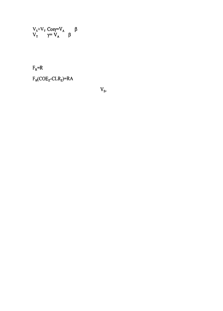
a) Horizontal plane : If the forces on the horizontal plane are considered (Figure lc), aerodynamic
driving force
acting on the sail at the centre of effort (COE) is balanced by the hydrodynamic
resistance force (R) acting on the hull at the centre of lateral resistance (CLR).
The horizontal aerodynamic force
must be balanced by a hydrodynamic side force
Such a side force can only be generated by giving the hull a leeway angle
for a symmetric yacht
form. Increasing the speed of the yacht increases the aerodynamic force, hence the leeway angle
must be increased to balance the yacht.
But this also causes an increase in the resistance,
consequently reduction in yacht speed. The moment generated due to the distance between
and COE, must be compensated by rudder moments, which in turn increases the resistance. In a
well
balanced yacht design, CLR must correspond to COE for optimum performance.
b)
Cross Sectional Plane :
The aerodynamic heeling force
and hydrodynamic force (F,)
creates a heeling moment which is balanced by mainly hydrostatic righting moment of A RA (Figure
1 b). Such a balance necessitates a heel angle under sailing conditions. As the aerodynamic lateral
force increases by the yacht speed, the heel angle must also increase. The aerodynamic force in the
vertical direction is at a smaller magnitude, and balanced by the increase of hull draft (sinkage).
c) Logitudinal Plane
: The longitudinal and vertical forces (Figure la) are balanced as given in
the previous planes. The trimming moment
is caused by the difference of aerodynamic and
hydrodynamic force acting points in vertical direction
and balanced by trim angle
change.
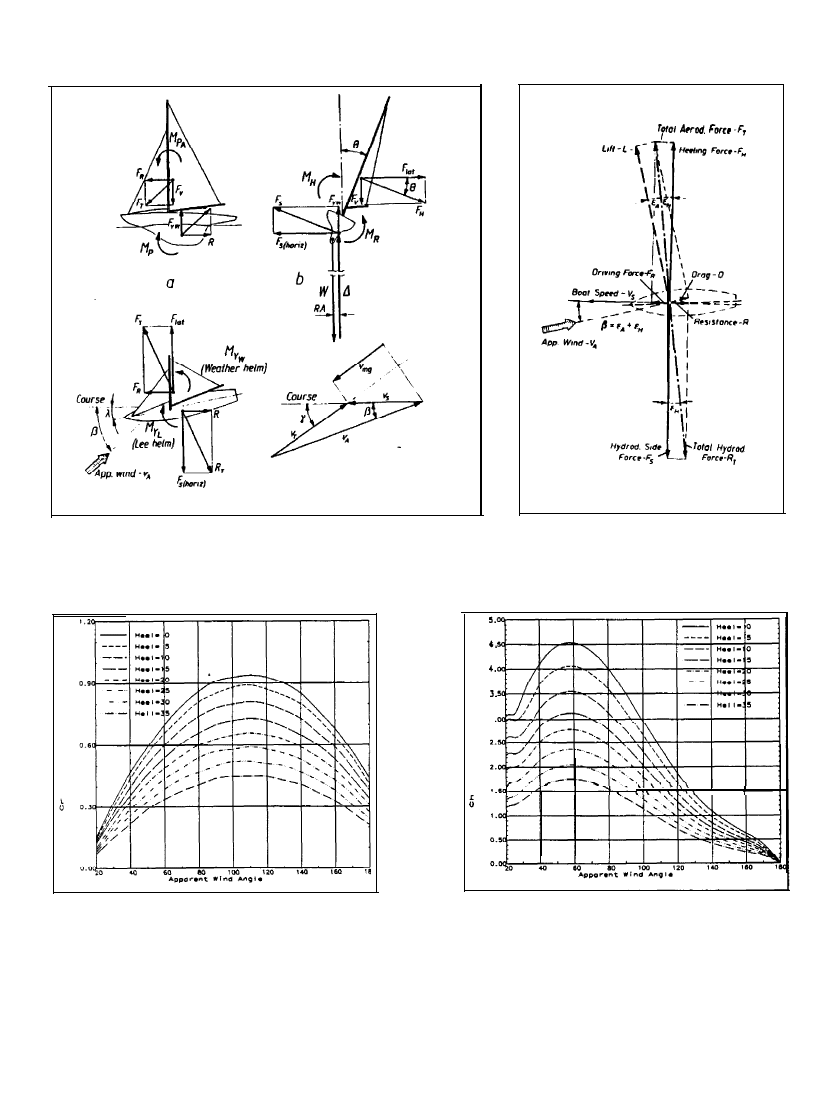
AERODYNAMIC FORCES
The sails behave like thin aerofoil at an angle of attack. The shape of the aerofoil is depend
on the flat, or reef, given by the yachtsmen. Aerodynamic drag and lift components are generated
at the same direction of apparent wind and normal to apparent wind respectively (Figure 2). The
angle between lift and total aerodynamic force represents aerodynamic efficiency (Cot
These forces can also be represented in the axis system defined by yacht course, which can be
expressed as driving force and heeling force.
Sin Cos = 0.5
(2)
Cos + D Sin = 0.5
Assuming maximum lift efficiency is obtained for the sail, driving force, heeling force can
be obtained as a function of apparent wind angle
An example of such case is given in Figure
3a and 3b.
Although aerodynamic driving force and heeling force are not effected by the leeway angle,
they are highly effected by the heel angle. As the heel angle increase both driving and heeling
forces are reduced with increasing heel angle (Kerwin 1976), which can be assumed to be linear.
=
(3)
=
(l-b 9)
Driving force and heeling forces for a particular sail rig can be determined by :
a) Aerodynamic theory, by use of lifting line/lifting surface calculations (Milgram 1970)
b) Wind Tunnel tests (Marchaj 1990)
c) Full Scale Trials (Davidson 1936)
HYDRODYNAMIC FORCES
The flow about hull at a heel and a leeway angle is quite complex due to both asymmetry
and the interface between water and air. Hence assumptions must be introduced to simplify the
force-moment balance.
Firstly resistance force can be assumed to be made up of a viscous
component associated with skin friction and form drag, and a pressure component associated with
wavemaking. Resistance change by the heel and leeway is assumed to consist of only pressure
component which can be scaled from model tests to yacht scale by Froude’ method and have no
influence on viscous resistance.
(4)
a)
Viscous Resistance
: Viscous resistance originates from the energy lost in
frictional loses and creating vortices, turbulence. Frictional resistance can be estimated from
0.5 WSA
(5)
where is skin frictional line which can be obtained from ITTC 1957 or Schoenherr lines;
Re
(6)
where Re is calculated by an effective length for the hull typically 0.7
i.e.
(7)
Form drag is due to three dimensional effects of viscous flow, and can
equal to
form coefficient can be obtained from Prohaska method
recommendations, a typical example is given in Figure 4. Frictional drag of hu
must be calculated separately,
be assumed to be
following ITTC
11, keel and rudder
b)
Wave Resistance
: Wave resistance is assumed to be the difference between total resistance
and viscous resistance in upright condition, i.e. zero heel angle and zero leeway angle, mainly
consists of energy lost in creating waves. Prediction of wave resistance of a yacht is difficult due
to the shape of the hull. Delft yacht series (Gerritsma et al 1991) forms the main data source in the
literature.
In practice towing tank test are used as the most reliable method available.
c) Resistance due to Heel
: Resistance change between the heeled case and upright condition
is called resistance due to heel. The resistance change due to heel at zero side force is governed by
the hull shape. A narrow yacht with circular sections would experience practically no change in
resistance with heel at small angles, a reduction may also be possible. Meanwhile a yacht with large
beam at the midship and fine ends would experience significant change. Heel resistance is expressed
by Gerritsma et al (1992) as :
WSA
(8)
d)
Induced Resistance
: As the hull sails with leeway, lift is generated which in turn causes
an increase in the resistance, called induced drag. The induced drag is principally function of the
effective aspect ratio of hull-keel combination and square of the sideforce coefficient.
WSA
WSA
(9)
where C, depends on the shape of the keel, Froude number and heel angle, and can be expressed as
Fn
(10)
In addition to the resistance, the hull experiences a lift force with increasing leeway angle.
In a racing yacht lift is mainly due to keel (up to 80 %). The hull and rudder contributes 20-50 %
of the lift. Gerritsma et al (1993) gave the horizontal component of side force as a function of
leeway angle, and froude number :
0.5 WSA
+
Fn
(11)
A hydrodynamic efficiency (cot
can be defined similar to the sail case. As
aerodynamic and hydrodynamic forces are balanced, the angle of apperant wind must be equal to
summation of aerodynamic and hydrodynamic efficiency angles
(Figure 2).
TOWING TANK TEST TO DETERMINE HYDRODYNAMIC FORCES
Since Davidson (1936) introduced the principles of yacht testing, towing tanks have been
utilised in performance prediction. The development of
Australia
II led to a combination of tank
testing and velocity prediction programs for accurate speed predictions, such as required by
Americas Cup designs.
Analytical methods are also introduced as an alternative to the tank testing. However the
accuracy of such methods are still limited, and their use are usually restricted to preliminary
investigation of design alternatives, to reduce the tank testing expenses.
Two types of model
experiments have been utilised by the experimental tanks (Larsson 1990). Free to heel approach
simulates the aerodynamic forces at the centre of effort (COE) and model is free to trim, heel, and
yaw. Hence all the aerodynamic forces must be determined before the experiments and different
set of experiment must be conducted for any change of sail configuration. The second approach
fixes the heel angle and leeway angle. Resistance, and sideforce are measured for a set of heel
angles and a set of leeway angles. An iterative technique can be applied to find a balance position
from this data for a given sail configuration. This approach has been utilised for the current work.
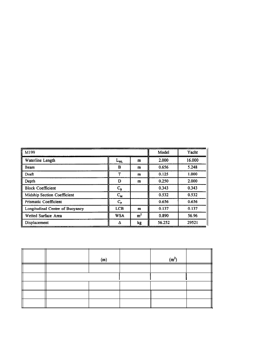
A series of yacht tests have been conducted in ITU Ata Nutku Ship Model Testing
Laboratory (ANSMTL). The towing tank is 160 m long, 6 m wide, and 3.4 m deep. A typical
yacht model at l/8 scale has been used in the tests (see Table 1). Model and five keels with sections
of NACA 63A0 15 were built from wood and turbulence studs at 25 % behind the leading edge were
used on both hull and keels. In all tests the model was free to trim and sinkage, but fixed to heel,
yaw and sway.
Table 1: Model and yacht characteristics
Keel
B
C
D
F
H
Max Keel Length /
Depth
Model Length
0.1326
0.265
Aspect Ratio
1.0
Keel Projection
Area
0.0703
Sweptback
Angle
20.0
0.1875
I
0.187
0.5
0.0703
20.0
0.1075
0.325
1.5
0.0703
20.0
0.1279
0.375
1.0
0.0703
15.5
0.1268
0.375
1.0
0.0703
15.5
Table 2: Keel characteristics
Measurement system consisted of a six component balance to measure resistance, side force,
heeling moment, and yaw moment. An LVDT and a rotary potentiometer have used for sinkage and
trim angle measurements. Bridge balance-amplifier system has been used in combination with six
component balance to amplify signals.
All measurement were recorded by a PC based data
acquisition system and averaged (Dayi 1991).
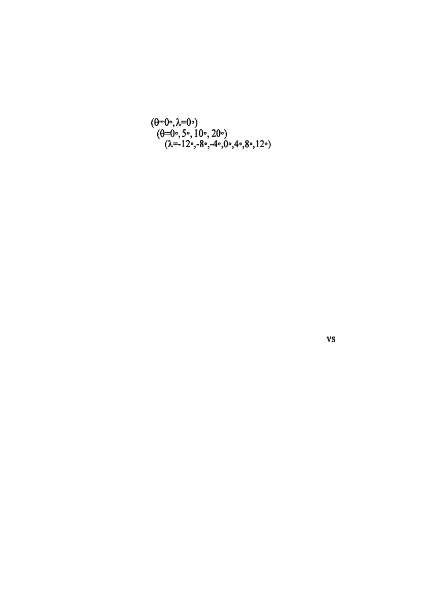
The following procedure has been followed in the experiments :
a) Upright condition is tested
for 11 speeds
bl) Model set for a heel angle
b2) Model set for a leeway angle
b3) Model tested for four speeds
THE EFFECT OF HEEL ANGLE AND LEEWAY ANGLE ON RESISTANCE AND
SIDEFORCE
The effect of heel on resistance is generally to increase resistance (Figure 8). However some
of the tank results show resistance decrease with heel angle increase. This is attributed to the wetted
surface area decrease in heeled conditions.
If the hull-keel-rudder combination is considered as an symmetric aerofoil, the lift,
i.e.sideforce, and resistance is increased by increase of angle of attack, leeway angle. The increase
in resistance, i.e. induced drag (Figure 9), is proportional to the square of the sideforce. This can
easily be seen from Figure 12 and 13.
The effect of leeway angle on sideforce is demonstrated in Figure 10. Sideforce is
proportional to the leeway angle. At the highest speed tested (10 knots) and at high leeway angles
(above 8 degrees), a decrease in sideforce was observed. This is resulted from the separation at high
angle of attack similar aircraft stall. A nondimensional plot of leeway angle
sideforce is given
in Figure 11, displaying speed independence of sideforce coefficient as long as separation is avoided.
Typical sideforce square vs resistance curves are drawn in Figure 12 and 13 for two keel
aspect ratios. In general the curves are almost linear, indicating induced drag is proportional to the
sideforce square. As the speed increases the slope of the lines are decreases, hence a Froude number
dependence in induced drag can be expected.
A comparison of two figures reveals that the high aspect keel is more efficient to generate
side force with least drag penalty, which is expected from fundamental aerodynamics theory.
Such
conclusions are also supported by polar performance plots.
CALCULATION OF A YACHT PERFORMANCE
Prediction of yacht speed for a given true wind angle and wind speed can be calculated by
an iterative calculation procedure called velocity prediction program (VPP). Such a program has
been developed in ITU (Helvacioglu and Insel I994). The method utilises the towing test data and
aerodynamic data consisting of lift and drag coefficients of a specific sail rig. In the current work
Gimcrack data by Davidson (1939) is utilised as a benchmark (Marchaj 1990).
Firstly two equations are defined from velocity triangle (Figure lc) as:
cos
Sin
Sin
(12)
(13)
Secondly the balance equations are simplified by assuming vertical forces are negligible, CLR
and COE are coincident on the horizontal plane, hence yaw moments are negligible and pitching
moment is compensated by the trim angle. The balance equations are reduced down to three for a
balanced yacht
F
=F
LAT
S-HOR
(14)
A
The iterative method does iterate
leeway angle, heel angle in turn to satisfy all five
equations for a true wind angle and wind speed. By changing wind angle from 0 to 360 degrees
and wind speed within a suitable range all performance values can be determined. A polar
performance diagram can be derived.
This diagram is the most suitable way to compare two
alternative designs such as keel variations.
The effect of keel aspect ratio and sweptback angle
is demonstrated in Figures 14 and 15 respectively by means of performance plots.
CONCLUSIONS
Sailing yacht balances aerodynamic and hydrodynamic forces. Such a balance is primarily
based on the leeway angle and heel angle, Performance prediction of this type craft can be based
on towing tank experiments with resistance and sideforce measurements. Future improvements are
planned by inclusion of yaw moment for the inclusion of rudder angle in the performance
predictions.
Test with bulbous and winged keels are underway in ITU to demonstrate their
capabilities.
The effect of heel is generally to increase the resistance, but no conclusions on the behaviour
of resistance increase could be drawn from current experiments.
Sideforce is proportional to the leeway angle, Decrease of sideforce can be observed if
separation is encountered.
Induced resistance is proportional to leeway angle, or square of the
sideforce.
REFERENCES
1)
CAMPBELL I, CLAUGHTON A. (1987), The Interpretation of Results from
Tank
Tests on 12 m Yachts, The Eight Chesapeake
Sailing Yacht Symposium.
2)
DAVIDSON K.S.M. (1936) , Some Experimental Study of Sailing Yacht, Transactions of SNAME, Vol:44.
3)
DAYI $. (1991), Yelkenli Direnc Deaeyleri, Yuksek Lisans Tezi, I.T.U. Fen Bilimleti Enstitusu.
4)
DESAIX P. (1975), Yacht Keels-An Experimental Study, SNAME The Second Chesapeake Yacht Symposium.
5)
GERRITSMA I.J., KEUNING J.A., ONNINK R. (19911, The Delft Systematic Series Yacht Hull (Series II) Experiments, SNAME
The Tenth Chesapeake Yacht Symposium.
6)
GERRITSMA I.J., KEUNING J.A., VERSLUIS A. (1993), Sailing Yacht Performance in Calm Water and in Waves, SNAME The
Tenth Chesapeake Yacht Symposium.
7)
HELVACIOGLU S., INSEL M. (1994), Yelkenli Teknelerin Performans Tahmininde Hidrodinamik Deneyler, I. Ulusal Deneysel
Mekanik Sempozyumu.
8)
KERWIN I.E. (1976), A Velocity Prediction Program for Ocean Racing Yachts, SNAME New England Sailing Yacht Symposium
9)
LARSSON L. (1990),
Scientific
Methods in Yacht Design, Annual Review of Fluid Mechanics.
10)
MARCHAJ C.A. (1990), Aero-Hydrodynamics
of Sailing, Adlard Coles.
11)
MILGRAM J.H. (1970), Sail Force Coefficients for Systematic Rig Variations, SNAME Technical and Research Report: R-10.
C
d
Figure 1: Balance of aerodynamic, hydrodynamic
and
hydrostatic forces and moments for a sailing hull
Figure 2:
Aerodynamic and
hydrodynamic forces on horizontal
plane
3.
.
I
I
I
Figure 3a: Typical sail driving force
Figure 3b: Typical
coefficient curves
coefficient curves
sail heeling
force
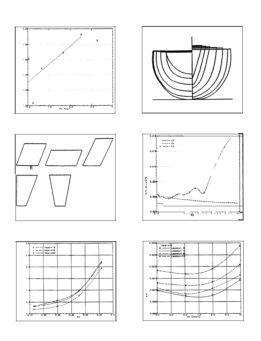
Figure 4: Prohaska analysis of form factor
Keel
Keel C
Keel D
Keel F
Keel H
Figure
6 :
Keel
forms
used
in
the
experiments
Figure 5: Yacht form used in experiments
(Ml 99)
0.19
,
, ,
0.21
0.33
0.40
0.47
0
Figure 7: Upright resistance characteristics
of model
Figure 8: The effect of heel on resistance
Figure 9: The effect of leeway angle on
resistance
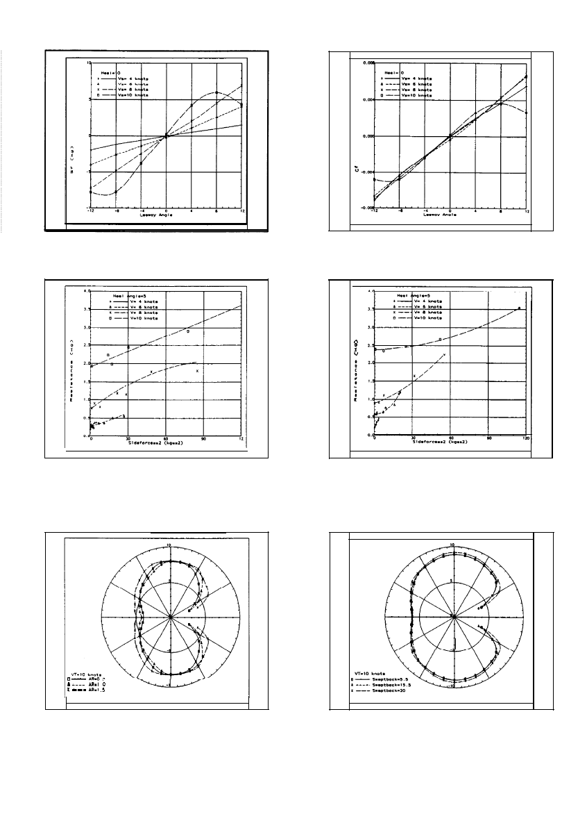
Figure 10: Side force by change of leeway
angle and
speed
Figure 1 I: Side
force
coefficient by change
of
leeway angle
Figure 12:
Resistance vs sideforce plot
for
Figure 13:
Resistance
vs sideforce plot
for
keel aspect ratio 1.5
keel aspect ratio of 1.0
Figure
14:
Polar performance
plots
with
keel aspect ratio change
Figure 15: Polar performance plots with
keel sweptback
angle change
Wyszukiwarka
Podobne podstrony:
Ebsco Cabbil The Effects of Social Context and Expressive Writing on Pain Related Catastrophizing
the effect of sowing date and growth stage on the essential oil composition of three types of parsle
Junco, Merson The Effect of Gender, Ethnicity, and Income on College Students’ Use of Communication
84 1199 1208 The Influence of Steel Grade and Steel Hardness on Tool Life When Milling
Divergent effects of chaperone overexpression and ethanol supplementation on IBs formation
knowledge transfer in intraorganizational networks effects of network position and absortive capacit
The Effects of Performance Monitoring on Emotional Labor and Well Being in Call Centers
76 1075 1088 The Effect of a Nitride Layer on the Texturability of Steels for Plastic Moulds
Curseu, Schruijer The Effects of Framing on Inter group Negotiation
A systematic review and meta analysis of the effect of an ankle foot orthosis on gait biomechanics a
Glińska, Sława i inni The effect of EDTA and EDDS on lead uptake and localization in hydroponically
Understanding the effect of violent video games on violent crime S Cunningham , B Engelstätter, M R
The Effect of Childhood Sexual Abuse on Psychosexual Functioning During Adullthood
On the Effectiveness of Applying English Poetry to Extensive Reading Teaching Fanmei Kong
The Effects of Psychotherapy An Evaluation H J Eysenck (1957)
The effect of temperature on the nucleation of corrosion pit
The Effect of DNS Delays on Worm Propagation in an IPv6 Internet
więcej podobnych podstron