
Pilot Study: Two Storey Load Bearing Straw Bale Wall University of Western Sydney. July 2000
A Pilot Study examining the Strength, Compressibility and
Serviceability of Rendered Straw Bale Walls for Two Storey
Load Bearing Construction.
Michael Faine and Dr. John Zhang
University of Western Sydney, Australia
ABSTRACT: A pilot study of a wall constructed from straw bales was carried out. The
objective was to examine the suitability of such walls for two-storey residential construction.
The emphases were placed on the strength, compressibility and serviceability of the rendered
straw bale wall. The full-scale wall was tested to failure in laboratory conditions. The result
shows that it is feasible to construct a two-storey wall using such system. The test results were
compared with the recommendation provided by some of the codes of practice. It was found
that the wall has adequate capacity for a two-storey wall construction. Other issues, such as
constructability, detailing, and compressibility were also examined in this paper.
Keywords: compressibility, constructability, infill, load bearing, render, straw bale,
sustainability, wall.
1. Introduction:
This pilot study was the result of some funding being made available to the School of
Construction and Building Sciences in mid 2000. The study area reflected the authors’ interest
in this material and was in keeping with the University’s mission statement of contributing to
a sustainable world through both research and teaching.
The authors’ background is that of practising architect/lecturer and structural engineer/senior
lecturer respectively. Both were aware of this style of building from a literature review and
were intrigued by the structural and practical aspects of construction using this material.
Straw bale construction is not new. Early examples date to the turn of the previous century in
Nebraska (USA)
where enterprising homebuilders utilised a waste material to construct well
insulated walls for their houses. Put simply such buildings were constructed from straw bales
as “large blocks” and then rendered or plastered with an assortment of finish to weather proof
the building. Over time this became known as the ‘Nebraska style’, some such examples still
exist to day.
There are two types of wall construction; load bearing and bale infill techniques. Each has its
own unique set of advantages and is often the preference of the owner/builder and the
influence of the building code officials. With respect to the code aspect, infill type techniques
may be preferred, as the bales are not necessarily contributing to the stability of the frame.
Usually large timber sections are employed in this type of building with all the attendant and
demonstrated ability of timber structures. A practical aspect might also be the construction of
the frame, allowing for a roof to be put in place ahead of the walls and therefore allowing a
degree of weather protection to the straw during the course of construction.
1
University of Western Sydney Mission Statement 1998
2
Steen A, Steen B, Bainbridge D Eisenberg D 1994 The Straw Bale House, Chelsea Green Publishing Company
First International Conference on Ecological Building Structure, Santa Sabina Centre, San Rafael, California July 2001
1

Pilot Study: Two Storey Load Bearing Straw Bale Wall University of Western Sydney. July 2000
Either way, many straw bale buildings have been constructed around the world to date but the
structural aspects of this material have not been as clearly defined compared to more
‘conventional’ construction materials. However codes do exist (particularly in the USA)
which delineate how bales should be used on site for both load bearing and infill type
construction (Austin Straw Bale Code
codes stipulate limits for the ratio of height to thickness (5.5:1) and ratio of length to
thickness (15.5:1) for load bearing walls.
This pilot study was set up to examine what would happen to a two-storey section of a load
bearing straw bale wall as it was uniformly progressively loaded by a uniformly distributed
load. The limitation of height to thickness would seem to preclude the use of load bearing
straw bale walls from two-storey house construction as these limitations would only allow a
wall of approximately 2500mm height to be constructed.
The significance of such research was to demonstrate either the ability of such a wall to either
withstand such loading or fail and therefore contribute to the wider field of knowledge with
respect to this type of construction. Two-storey load bearing construction may also allow for
houses with a smaller “footprint” to be successfully constructed, therefore increasing the
range and type for this form of construction. This pilot study however does not examine the
effects of wind loading on such walls that will be the topic of another research effort.
Previous studies to date have been undertaken by Bou-Ali (University of Arizona)
(University of Arizona), Carrick (University of New South Wales)
the structural adequacy of this type of construction. Researchers have also identified the very
good insulation properties of rendered straw bales (Canada)
and its attendant fire resistance
qualities. However moisture in and through the wall have sounded some alarm bells for the
obvious problems of rot and then eventual collapse, further studies are being undertaken in
this area.
2. Current Construction Technology:
This section will be limited to a discussion on the techniques associated with load bearing
construction. The main issue to be faced in dealing with straw bales is to adequately achieve
pre-compression of the bales to avoid the problem of both short and long term settlement
(shortening) of the wall. Such a problem obviously has a great impact upon the construction
of doorways and windows not to mention the potential for cracking and damaging the render
(plaster) mix applied to the wall as the finish.
Straw bale walls have been constructed both from in-ground conventional strip footings and
from integrated footings and concrete slab. Other types have been tried, such as rubble filled
footings, earth filled tyre footings usually to minimise or avoid the use of reinforced concrete.
3
Austin Straw Bale Code 1997, City Of Austin, www.io.com/~whetfunk/sbatcode
4
City of Tucson and Pima County Arizona Building Code, www.sustainable.doe.gov/codes/azstraw
5
California Code AB1314, California State Government Web site
6
Bou-Ali G. 1993 Straw bales and straw bale wall systems, Master Thesis University of Arizona
7
McCabe J. 1993 Masters Thesis University of Arizona
8
Carrick J 1998 Preliminary Test Results for Straw Bale Walls, Building Research Centre UNSW (unpublished)
9
1995, Thermal and Mechanical Properties of straw bales as they relate to a straw house, Canadian Society of
Agricultural Engineering, Ottowa, Ontario
First International Conference on Ecological Building Structure, Santa Sabina Centre, San Rafael, California July 2001
2

Pilot Study: Two Storey Load Bearing Straw Bale Wall University of Western Sydney. July 2000
This material is viewed as being high technology with high-embodied energy. The usual
details of waterproofing, vapour control, termite and pest control are observed with a variety
of techniques available for both tie down of the roof frame and pre-compression of the wall.
These range from reinforcement rod being extended from the footing, through the straw bale
wall to the top plate. This is then ‘screwed down’ to compress the wall and for the tie down
effect of the roof and/or the floor frame. Another method is to use an air bag attached to the
top of the wall frame and held in place by straps (Fibrehouse system by Chapman and
Platts)
. The bag is then inflated and the wall is compressed down and held firmly in place by
tensioning on the straps. Once the desired compression is achieved the bag is removed.
Another method is to use high tensile fencing wire straps looped around both the footing and
the top plate and tensioned by means of “gripples”, similar to constructing a wire fence. The
wire is usually spaced at about 450 – 600mm centres and is alternatively fastened from both
sides of the wall. The tensioned wire then becomes an integral part of the structure.
Usually bales are laid on flat in a stretcher or running bond, often being pinned through their
centres to the footing or floor structure and pinned to each other at corners and elsewhere as
required. Construction can be quite quick, unskilled labour can be used with chain saws,
mallet and ‘whipper-snippers’ providing the finishing effects.
If the wall is to be rendered using cement based render then a wire mesh (chicken or aviary
wire) is stretched from top to the bottom plate. Walls finished in an earthen render do not
usually have this mesh.
The render being applied direct to the straw bale and forced into the
strands, this gives quite a good key for subsequent coats. There is some debate about the merit
of using cement based renders, they are certainly good for strength characteristics but others
have raised questions about the breathability of such walls to vapour. Moisture is of concern
for the longevity of the wall structure.
Top plates are generally framed from 100 x 50mm or 150 x 50mm timber constructed as a
ladder frame to span the width of the straw bale. Noggins at 600 or 900mm centres join the
timber frame members; some advocate the use of sheet plywood. Often associated with the
top plate is the roof tie down mechanism, being either a threaded rod or galvanised strap or
tensioned wires. Concrete bond beams have also been used as the top plate.
3. Design and Construction of the Full Scale Wall:
The University of Western Sydney has a well-equipped construction laboratory with a very
large steel reaction frame originally developed for the testing of steel and steel/concrete
composite columns under axial load up to 100 tonnes. This frame was used to contain the
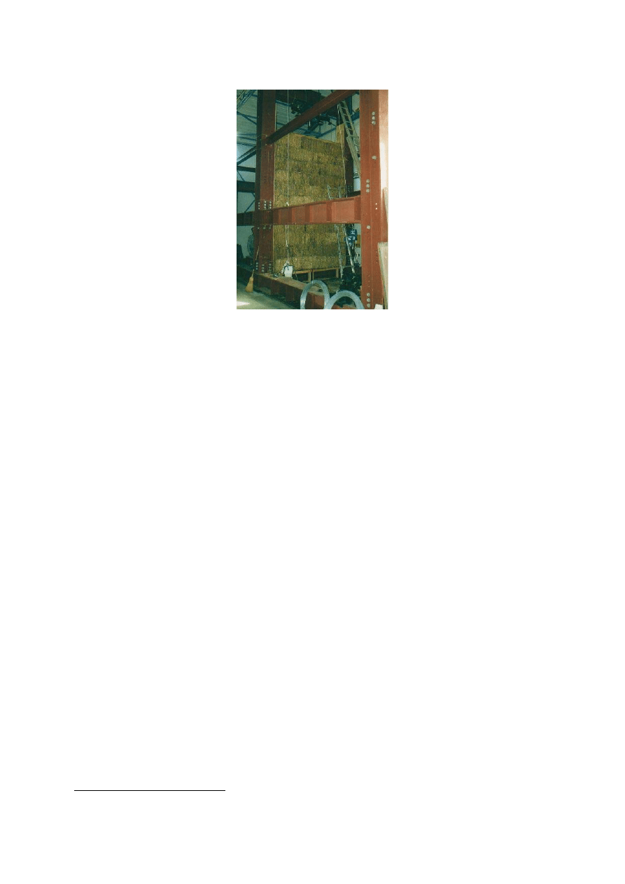
construction of the straw bale wall. Figure 1 shows the general frame arrangement with the
partly completed straw bale wall framed between the large structural steel columns. The steel
beams and columns were fabricated from 25mm thick steel, 400 x 400mm “I- beam” section,
courtesy of a research grant and BHP steel sections.
10
Chapman and Platts 1996 Developing and proof testing the pre-stressed Nebraska method for improved
production of baled fibre housing, Fibrehouse Ltd with Scanada Consultants Ltd, Ottawa, Ontario
11
Glassford J 2001 Straw Bale Building Technology Workshop Ganmain NSW (personal interview)
First International Conference on Ecological Building Structure, Santa Sabina Centre, San Rafael, California July 2001
3
Pilot Study: Two Storey Load Bearing Straw Bale Wall University of Western Sydney. July 2000
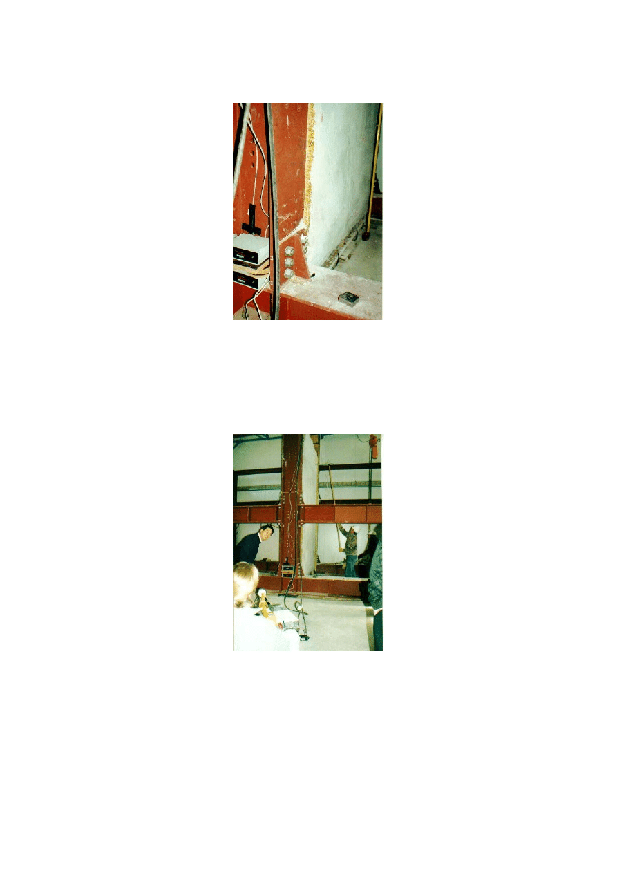
Figure 1 General view of steel test frame and partly completed wall (Photograph: P. Florence)
This picture shows the partly completed wall at the 8th course level contained within the steel
reaction frame. A layer of 17mm thick structural plywood was added to this course and
pinned to the bales. This was to done to help stabilise the wall.
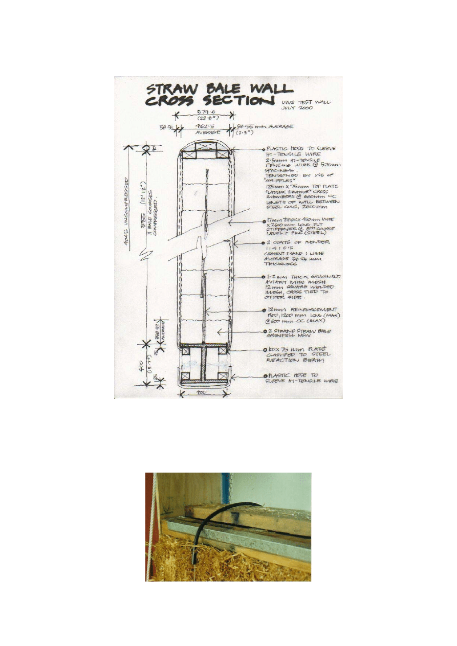
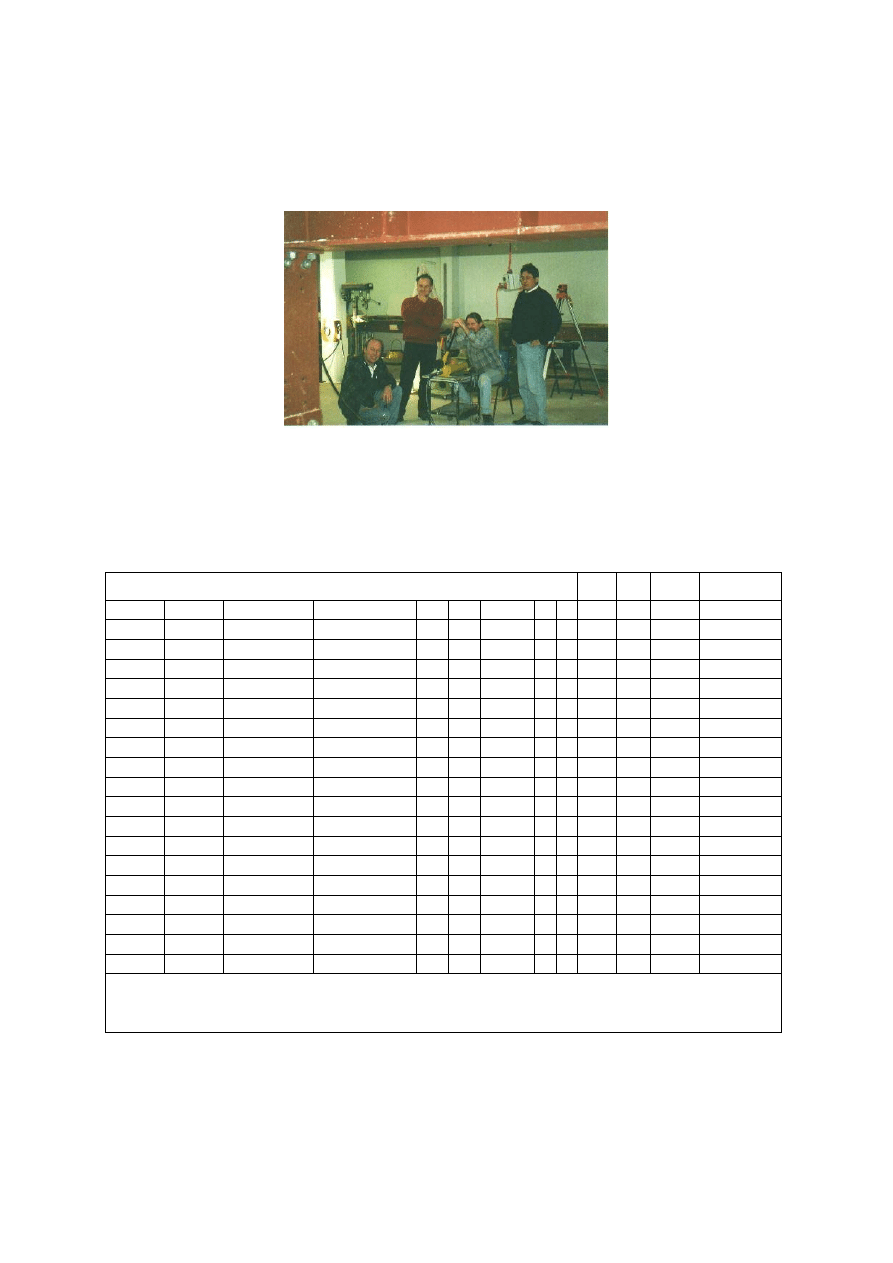
The wall was constructed to a height of 4045mm (uncompressed) being 11 courses in height;
the length of the wall was 2600mm between steel columns with a layer of 17mm structural
plywood placed against the steel columns to prevent the straw from expanding into the web of
the columns. The general arrangement for construction can be seen in Figure 2. Bales were
laid in stretcher bond pattern with a number of half bales. Bales were pinned over a 12mm
reinforcement rod that had been tack weld to the frame. Pinning was continued up through the
bales to the top course. The lower section of steel was assumed to simulate the concrete
footing. A timber infill frame was constructed between the flanges of the bottom steel beam
to allow for fixing of the wire mesh. Construction generally followed details reviewed from
the literature and from interviews (Mitchell R.)
The top plate was constructed from 125 x 75mm timber joined together as a ladder frame. An
additional length was placed centrally to help distribute the load from the hydraulic rams. The
high tensile fencing wire was run as a loop under the “footing” and carried up and over the
top plate. A length of galvanised iron angle was placed at both top and bottom plates to
provide for a radius turn for the wire to prevent a sharp edge from cutting the wire under load.
This can be seen in Figure 3.
The high tensile wire was 2.5mm thick and is commonly used for fencing applications. The
wire was sleeved in a plastic hose and the loop was joined on alternate sides of the wall. This
was then tensioned by use of “gripples” and a fencing tool. The wall was compressed a total
of 90 mm to give a finished height of 3955mm. Bales were then nocked into place and
trimmed by “whipper-snipper”. No attempt was made to achieve a perfectly true and plumb
wall, rather some irregularities remained as the authors believe that this simulates general
building construction.
12
Mitchell R. 2000 Zone Zero Architects Springwood NSW (personal interview)
First International Conference on Ecological Building Structure, Santa Sabina Centre, San Rafael, California July 2001
4
Pilot Study: Two Storey Load Bearing Straw Bale Wall University of Western Sydney. July 2000
Figure 2. Straw Bale Wall Cross-Section. (Illustration M. Faine)
A layer of 1.2mm thick galvanised welded wire mesh was then stretched between top and
bottom plates and fixed into position. This was also stitched to the other side of the wall to
bring the mesh in close to the straw bale surface.
Figure 3: View of top plate assembly showing sleeved wire loop. (Photograph P. Florence)
First International Conference on Ecological Building Structure, Santa Sabina Centre, San Rafael, California July 2001
5
Pilot Study: Two Storey Load Bearing Straw Bale Wall University of Western Sydney. July 2000
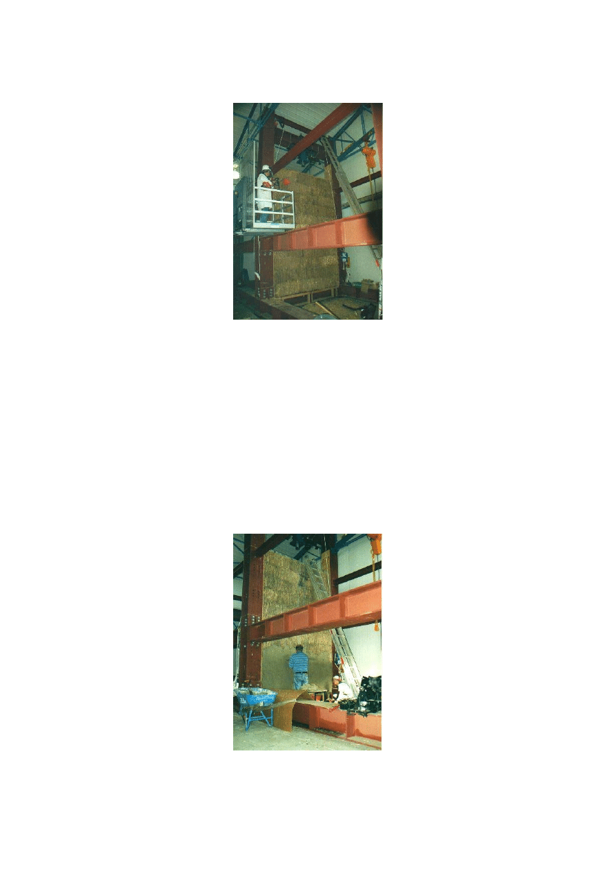
Figure 4: Trimming wall to size. (Photograph P. Florence)
The wall was trimmed to remove stray fibres and nocked into a reasonable straight line prior
to the wall being compressed. Once the team was satisfied with the result the rendering
process began. Two coats were applied over a period of two weeks, with the coats being
applied in about a day and a half by a team of four (inexperienced) renderers. The mix design
was 1: 4: 0.5 being cement: sand: lime. This was a strong mix with the addition of the lime to
‘self heal’ any later cracking. The rendering process can be seen in Figure 5.
This was a tedious part of the process and very labour intensive. Our research funds did not
extend far enough to warrant using a spray application (this process alone would have
accounted for approximately 25% of our funds). Render was applied to an average depth of
approximately 60mm.
Figure 5: Render application over mesh and straw bales. (Photograph P. Florence)
The straw bales used in the construction of this wall were sourced from ‘Elderslie’ at Grenfell
NSW and were two string bales 840 x 460 x 360mm dimension. The bales were sourced from
First International Conference on Ecological Building Structure, Santa Sabina Centre, San Rafael, California July 2001
6
Pilot Study: Two Storey Load Bearing Straw Bale Wall University of Western Sydney. July 2000
this farm as the farmer had prepared bales for other straw bale projects and was familiar with
the requirements to provide tightly bound bales. The average moisture content was calculated
to be 12.11%, well within the allowable range (see appendix). The California Code permits a
moisture content of up to 20% of the total weight of the bale.
construction guideline advocates a similar limit.
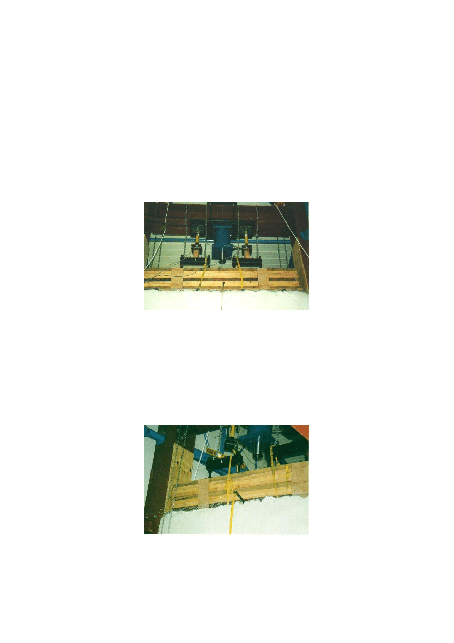
The test set up was fairly simple. Two 10 tonne capacity Enerpac hydraulic rams were
coupled together and attached to the top steel reaction frame. 2 x 10 tonne load cells (HBM
Agezelle) were placed in between the ram and steel spreader bars designed to distribute the
load at 450 mm centres were stacked on top of the plate. The general arrangement can be seen
in Figure 6.
Figure 6: Hydraulic rams and top plate assembly. (Photograph P. Florence)
The load cells were calibrated and the two electronic display units were set up to give a read
out of the load from each hydraulic ram in newtons. During the test the readout from each unit
would be noted against time and deflection/deformation of the wall. A steel scale had been
attached to either side of the wall at the midpoint and this was to be read against a static point
set up from the floor of the laboratory. Figure 7 shows the steel scale attached to the top plate
and Figure 8 shows the other end of the tape and the data acquisition units.
Figure 7: View of top plate, ram and measuring tape. (Photograph P. Florence)
13
State of California Health and Safety Code, Guidelines for Straw Bale Construction www.skillful-
means.com/CALIFORNIA
14
New Mexico Straw-bale Construction Guidelines www.earthbuilding.com/nm-straw-bale-code
First International Conference on Ecological Building Structure, Santa Sabina Centre, San Rafael, California July 2001
7
Pilot Study: Two Storey Load Bearing Straw Bale Wall University of Western Sydney. July 2000
Figure 8: View of electronic display units and end of tape. (Photograph P. Florence)
Two theodolites had also been set up to observe readings from pre-designated marked
positions on the face of the walls to observe any lateral movement. Figure 9 shows how these
measurements were to be taken and recorded as the loading progressed. These measurements
were recorded to determine if the wall had moved sideways during the loading process.
Figure 9: View of lateral measurement process. (Photograph P. Love)
4. Test Observation and Results:
The test was carried out on Friday 4 August 2000 and took about one hour to complete. The
process was to progressively apply more load to the wall via a hand pump hydraulic unit, note
the load cell readings, time and deflection/deformation of the wall. Various members of the
team had been assigned certain tasks to observe, record and photograph the event.
First International Conference on Ecological Building Structure, Santa Sabina Centre, San Rafael, California July 2001
8
Pilot Study: Two Storey Load Bearing Straw Bale Wall University of Western Sydney. July 2000
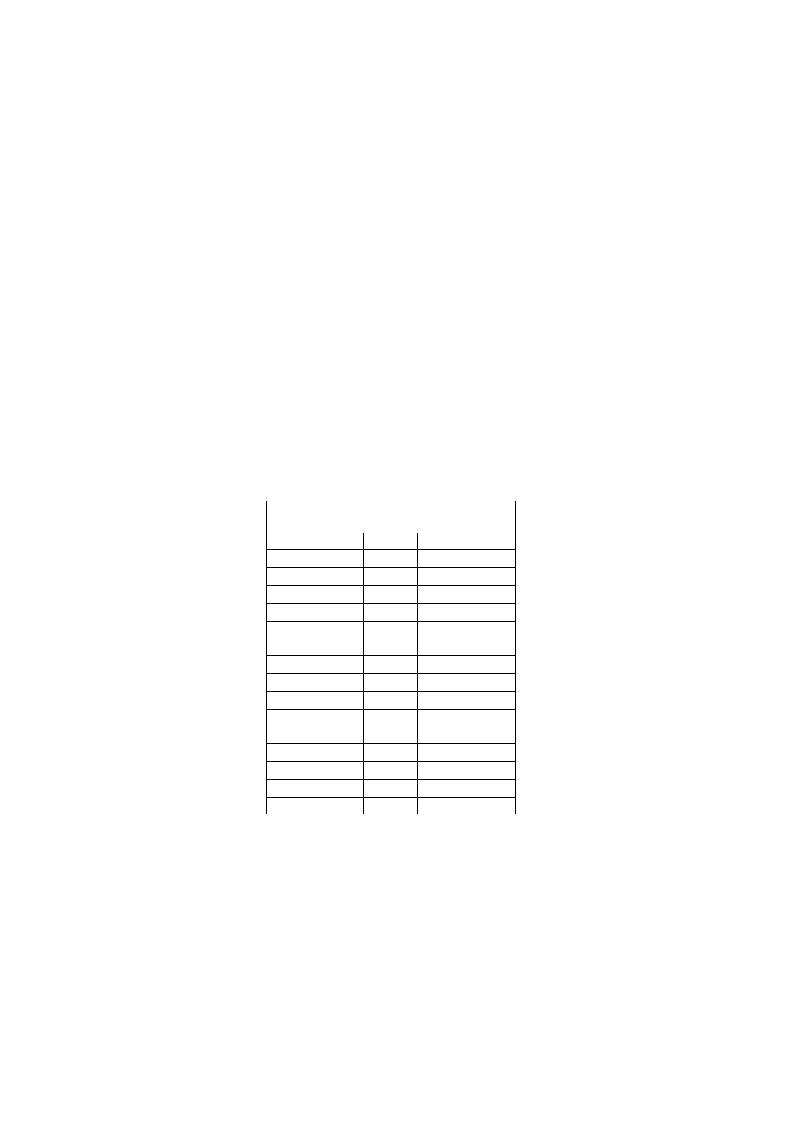
Figure 10 records some of the team members in action. The hand pump can be clearly seen
with the theodolites set up in the background.
Figure 10: Some of the test crew in action. (Photograph P. Love)
The team worked through clearly defined cycles lasting about 2.5 – 3.5 minutes to
progressively load the wall, note and record impressions, note and record actual load and
deformation/deflection and note the time. Each cycle represented an increase in load of
approximately 5kN. The results of this cycle can be seen in Figure 11
Figure 11. Test Result data (Source: M. Faine and J. Zhang)
Straw bale test results Friday 4 August 2000
Load 1 Load 2 left vertical right vertical 3 4 5
6 7 1
2 Time Comments
south
north
Top Middle
Edge half
0 0 2859 2857
91
145 109
80 90 231
185
start
1760
2506
2859
2857
92 145 109
81 90 231 185 2.53 end of cycle
3884 5001 2859
2857
92
145 109 81 90 231
188
8.32
9899 9919 2859
2855
91
144 108 80 91 230
186
13.58
14800 15036 2860
2853
92 145 108 80 91 231 186 18.17
19200 20092 2861
2850
93 146 108 80 90 231 186 21.28
25207 25209 2859
2845
92 146 110 80 91 232 186 24.42
30193 30196 2850
2840
93 146 108 81 88 231 188 27.30
36056 36875 2840
2834
90 146 107 83 90 232 187 30.55
40100 40391 2822
2818
89 146 110 80 85 232 188 34.55
45080 45345 2790
2755
85 142 [109] 78 86 231 183 39.50
50485 50071 2790
2740
85 140 [105] 78 86 230 185 42.45
55061 55620 2787
2730
82 140 [106] 78 85 232 187 43.35
60496 60221 2786
2720
80 138 [110] 77 84 230 185 48.36
62500 63286 2782
2710
82 139 [106] 76 83 231 186 52.17
57.50
stop
Note 1: loads in kN
Note 2: vertical and horizontal measurements in mm
Note 3: figures in brackets were obtained by interpolation due to sight obstruction to face of north wall
Load 1 and 2 columns refer to the two loading cells. The left and right ‘verticals’ columns
(south and north respectively) refer to the vertical measurements of the steel tape measures.
The numbers across the top right of the chart with some designated as ‘top’, ‘middle’ and
‘edge’ refer to the pre-determined positions on the north face of the wall that were plotted
First International Conference on Ecological Building Structure, Santa Sabina Centre, San Rafael, California July 2001
9
Pilot Study: Two Storey Load Bearing Straw Bale Wall University of Western Sydney. July 2000
over time by theodolite. They provide an indication of the relative movement of the wall face
(either in or out of plane). Time is noted in the far right column.
For the first 14 minutes of the test no movement or cracking noises were recorded. After this
time cracking noises were heard most likely from the timber at the top of the wall. By 22
minutes some render had cracked away from the wall at the top but there were no obvious
signs of cracking developing on the face of the wall. By 28 minutes more cracking sounds had
been recorded with the wall developing a slight ‘bulge’ on the southern face. By 30 minutes
more cracking noises were recorded with some crushing sounds but still no sign of any cracks
appearing in the surface of the render. By 35 minutes more render was falling from the top of
the wall with the bulge at the centre and on the southern side becoming more obvious. At 40
minutes more render had separated from the top of the wall and at 43 minutes the render was
observed to be separating from the bottom of the north face. At 46 minutes the southern side
had compressed more than the north face and at 50 minutes the travel of the hydraulic rams
had been exceeded. By 57.50 minutes the test was stopped.
Figure 12 shows the applied load and the deformation of both the right and left hand sides and
an average figure for the wall.
Figure 12. Load versus wall deformation table. (Source: J Zhang)
Load
(kN)
Vertical Deformation (mm)
left
right
average
0 0
0 0
4.266 0 0
0
8.885 0 0
0
19.818 0 2
1
29.836 -1 4
1.5
39.292 -2 7
2.5
50.416 0 12
6
60.389 9 17
13
72.931 19 23
21
80.491 37 39
38
90.425 69 102 85.5
100.556 69 117
93
110.681 72 127
99.5
120.717 73 137
105
125.786 77 147
112
Of interest here is the negative numbers recorded for the left hand (south face) of the wall.
First International Conference on Ecological Building Structure, Santa Sabina Centre, San Rafael, California July 2001
10
Pilot Study: Two Storey Load Bearing Straw Bale Wall University of Western Sydney. July 2000
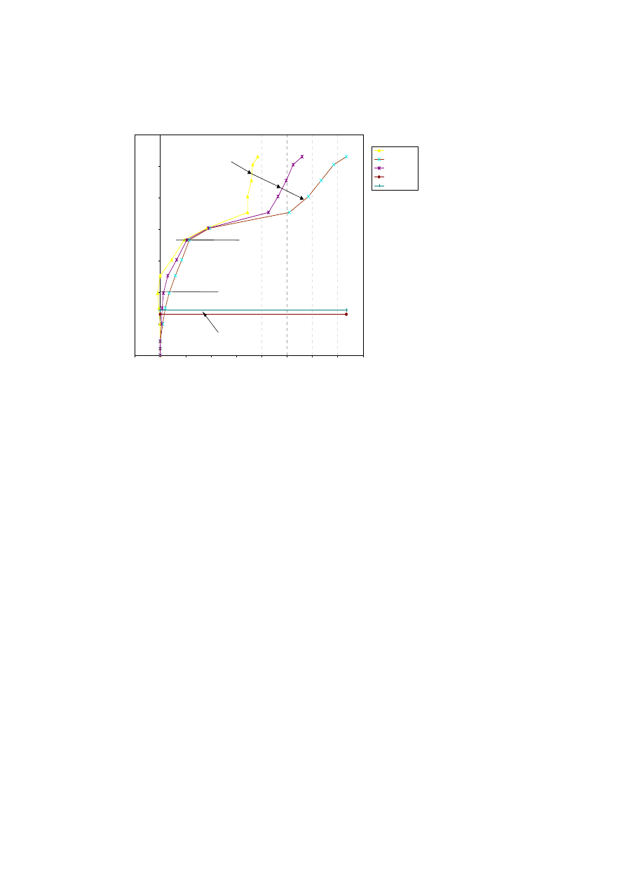
The results of this table have been shown in the following chart (Figure 13.)
Load vs deformation
0
20
40
60
80
100
120
140
-20
0
20
40
60
80
100
120
140
160
Vertical deformation (mm)
Loa
d (k
N)
left
right
average
pima code
California code
`73 kN, ultimate failure load
40 kN, safe working load
safe working load by Pima and California codes
Post-stiffening effect
Figure 13 Load Deformation Curve (Source J. Zhang)
The wall demonstrated some interesting and fascinating structural characteristics. Apart from
the obvious failure region when the load reaches about 80 kN, it also reveals that the post-
failure behaviour has a distinct feature of post-stiffening effect due to the compressibility of
the material.
When the wall is first loaded, the behaviour follows a typical linear path. The left side
deformation reading is negative indicating it is moving upward instead of downward as one
would expect. This is due to the eccentricity in the applied load and in the wall itself. This
eccentricity creates a significant bending effect so that the wall is bent toward the right hand
side.
For this reason the average deformation between the left and right provide a more meaningful
interpretation of the result. It can be seen on the average curve at the load level of just above
40 kN, there is a significant increase in deformation, demonstrated by the change of slope in
the curve. One would stipulate that due to the compression of straw bale, the interaction
between the straw and the cement render becomes less significant resulting in the ‘softening’
of the wall. As the load increases the wall starts to ‘yield’. At the load level of 70 kN there is
a significant increase in deformation, which marks the failure of the wall. This failure is
probably due to the significant separation between the straw bale and the cement render. As
the load increases further, the straw bale becomes fully compressed, therefore becoming more
solid as the load starts to increase further. Although this post-failure capacity cannot be used
in the design of straw bale wall, it does illustrate that the post-failure behaviour is rather
stable.
First International Conference on Ecological Building Structure, Santa Sabina Centre, San Rafael, California July 2001
11
Pilot Study: Two Storey Load Bearing Straw Bale Wall University of Western Sydney. July 2000
The maximum allowable stress that a straw bale wall can support depends on a number of
factors. Of these the wall slenderness (height/thickness) and the unsupported length ratio
(unsupported wall length/thickness) are the major influencing factors. The Pima County,
Arizona, Straw bale building code limits h/t ratio to 5.6 and L/t ratio to 13. The maximum
permissible stress provided by the straw bale alone is limited to 2.5 psi (17.24 kPa) in the
Pima Code. California’s model straw-bale code allows an L/t ratio of 15.7 and a maximum
allowable load of 2.77 psi (19.10 kPa). These allowable values are for straw-bale alone.
Virtually all straw-bale walls are rendered, the contribution by renders is significant, however
this contribution is difficult to quantify. King
suggests that the render should be regarded as
a thin wall restrained by straw bale at a discrete distance, and the strength model for the
concrete column/wall be applied. However that treatment only works if both straw-bale and
renders are directly loaded at the top. In this experiment only straw bales are loaded, the
loading applied to the render is indirect through the interaction due to bonding. The maximum
allowable values given in both the Pima and California codes are also plotted in Figure 13. If
the ultimate failure load is taken as 73 kN (48.44 kPa) and the safe working load is taken as
40 kN (26.55 kPa) when the loading curve ‘softens’ significantly, this gives an equivalent
safety factor of 1.82. When compared with both the Pima and California codes, their safety
factors are equivalent to 2.81 (Pima code) and 2.51 (California’s code), respectively.
The wall did not fail as expected; most of the team were anticipating that the wall would
buckle under load with parts of the render falling away from the face of the wall. In fact very
little cracking was observed to have formed in the face of the wall. Both faces of render had
acted like a ‘curtain’ and followed the compression of the wall. This can be clearly seen in
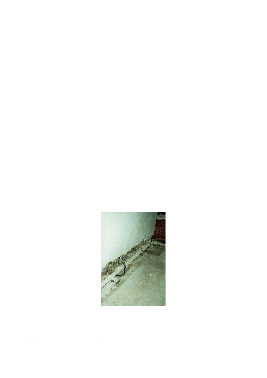
Figure 14, a view of the bottom plate of the wall. The high tensile wire loop has become slack
and has fallen as the wall had compressed, the render has stayed remarkably intact on both
faces.
Figure 14. View of bottom plate after test (Photograph P. Florence)
The top plate was also observed to have rotated during the test. It is possible that the load was
slightly off centre or that the straw was less stiff on one side. Another possibility could be that
15
King B.1996 Building of Earth and Straw Ecological Design Press
First International Conference on Ecological Building Structure, Santa Sabina Centre, San Rafael, California July 2001
12
Pilot Study: Two Storey Load Bearing Straw Bale Wall University of Western Sydney. July 2000
the wall was not perfectly plumb and square when constructed but was within reasonable
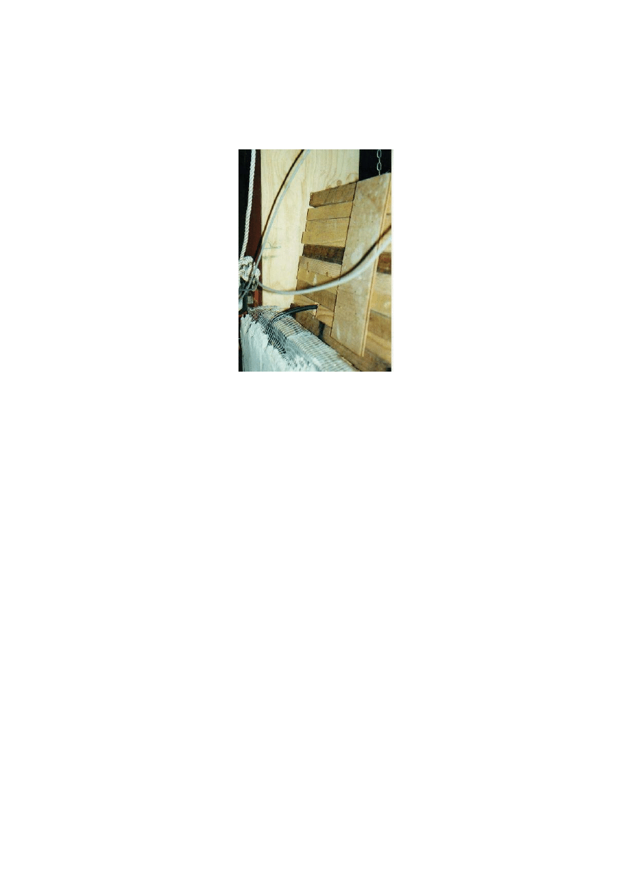
limits for a bale wall. Figure 15 records a view of the top plate after the test.
Figure 15. View of top plate after the test. (Photograph P. Florence)
The top plate had twisted progressively under load and possibly would have ‘tumbled over’ if
the test had been continued.
Following the test the wall was demolished. This was a difficult task to achieve until all the
wire strands and mesh had been cut by angle grinder. The wall was then pushed over by the
use of a forklift truck and the render skins peeled off (with some difficulty).
5. Recommendation and Conclusions:
From this test there are at least two aspects worth considering. The first relates to the
construction detail of a straw bale wall. It goes without saying that achieving the best pre-
compression of the bales (by whatever method) is very important. Pinning of the bales by
using reinforcing rod is probably ‘overkill’ but some pinning is required as the wall
progresses for practical reasons (stability). Providing some lateral stiffness was required at the
8
th
course level to prevent the wall from ‘swaying’ under the construction loads. This too was
pinned to the bales and together with the top plate construction formed a type of bond beam.
The location of the top plate in relation to the render finish is another important practical
aspect. This test allowed for loading of the straw bales in compression, as the top plates did
not directly bear on the render finish. At the safe working load of 40kN the deformation
(average) is about 5mm, quite tolerable but requiring careful detailing of the finish of the
render against adjacent surfaces (floor or slab) to avoid cracking of the finish.
The test also confirmed that this technique is suitable for two-storey construction but the
practical aspect of building in the first floor structure needs to be considered. Spray
application of the render finish would be preferred as hand application is very tedious work.
First International Conference on Ecological Building Structure, Santa Sabina Centre, San Rafael, California July 2001
13
Pilot Study: Two Storey Load Bearing Straw Bale Wall University of Western Sydney. July 2000
The second aspect worth considering is that of the structural behaviour of the test wall. The
safe working load limit of 40 kN is approximately 10 kN above the limits set by the Pima and
California Codes. These codes may be very conservative and further testing of straw bale
walls is warranted to determine ‘type’ characteristics suitable for inclusion into building
codes.
At the ultimate failure load of 73 kN some interesting comments can be made about straw
bale walls. Once this load limit has been reached straw bale walls compress unimpressively,
in fact the failure mode was unspectacular. For those of us watching the test in the laboratory
this was an unremarkable way to end the experiment. However it does mean that should a
straw bale wall be overloaded in residential construction the house owner could reasonably
expect to have a slightly ‘shortened home’, still carrying load.
Further work needs to be done on the interaction of the straw to render bond to determine
exactly how this behaves as a construction material. The bond between the straw and the
render was observed to be very strong, particularly at the time of demolition. This test has
shown that this material is excellent for constructing walls for residential purposes from a
structural point of view.
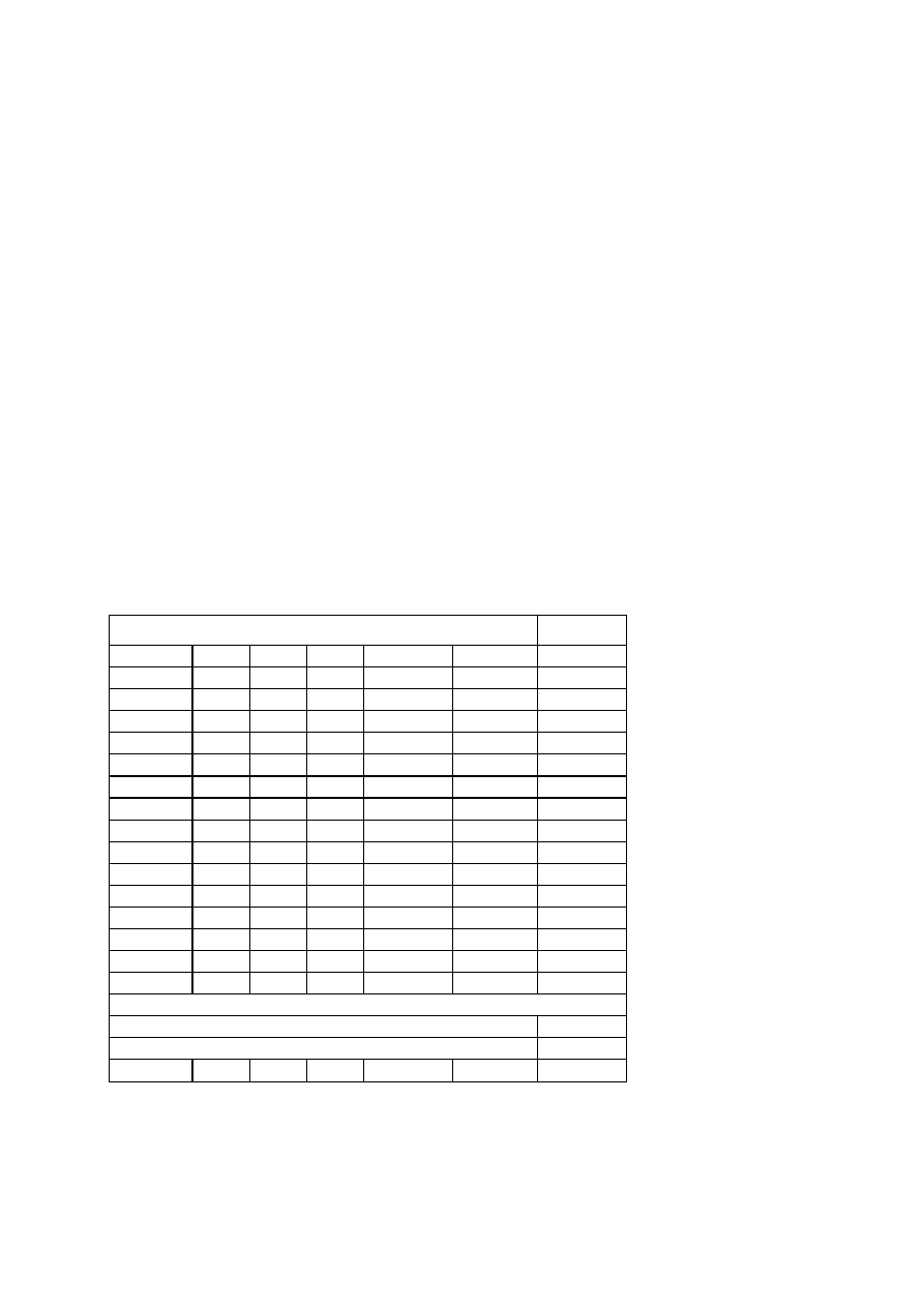
6. Appendix:
Table 1: Calculation of bale density and moisture content. (Source M. Faine)
Size of bales and weights as noted
length width depth kg 26 May kg 6 June kg 9 June
Bale 1
800 460 360
16.7
15.61
15.63
Bale 2
840 470 350
15.23
14.27
14.29
Bale 3
830 465 360
15.48
14.87
14.82
Bale 4
830 470 360
14.71
13.89
13.9
Bale 5
810 470 360
15.69
14.97
14.93
Bale 6
790 460 360
16.41
15.56
15.53
Bale 7
860 460 360
14.79
14.16
14.09
Bale 8
870 470 360
14.95
14.3
14.2
Bale 9
880 455 350
17.22
16.52
16.32
Bale 10
880 440 360
16.43
15.63
15.48
Bale 11
820 460 360
16.24
15.63
15.52
Bale 12
850 470 360
17.19
16.55
16.47
Averages 838.33
462.50
358.33
15.92
15.16
15.10
Note: Moisture content of straw bales was calculated at 12.11%
Note: 6 June reading 10:45 a.m. 11.2% R.H. 34.5 deg C
Note: 9 June reading 12.30 p.m. 10.9% R.H. 34.6 deg C
Note: random sample of 12 bales taken from the load delivered to the construction laboratory.
First International Conference on Ecological Building Structure, Santa Sabina Centre, San Rafael, California July 2001
14
Wyszukiwarka
Podobne podstrony:
j zhang us univeristies venture Nieznany
2 bedroom two storey house T shaped
Liu Z , Li W , Zhang S 2006
Zhang
2 bedroom two storey house(1)
J Storey Studia kulturowe i badania kultury popularnej streszczenie
Storey - Studia kulturowe i badania kultury popularnej, Podstawy teorii kultury
Zhang Ailing My writing
4 flat single storey building
W 1989 roku Storey wprowadził podział na twarde i miękkie zarządzanie zasobami ludzkimi, Zarządzanie
j zhang us univeristies venture Nieznany
Bioinformatics 2014 Zhang 497 505
Tao, Huang, Wang, Zhang, Zhang, Li (2010) Proposed diagnoztic citeria for interenet addiction
2 bedroom two storey house T shaped
PNAS 2005 Zhang 1029 34
2 bedroom two storey house
więcej podobnych podstron