
Thank you for using a DOWNLOADABLE WOOD PLAN. We hope you enjoy being
a part of this new hi-tech experience, and that you have fun building your woodworking
project.
Larry Clayton
Editor
WOOD
®
magazine
Adobe Acrobat Troubleshooting Guide
My printer won't print the text
Try setting the print quality at normal or economy rather than best quality or reduce dpi
to 150 rather than 300 dpi. These settings are selected in the printer setup or printer options.
Patterns are not printing full size
Make sure your printer is set to print at 100% and that “print to fit” is not checked.
These settings are selected in the printer setup or printer options.
HP printers
Make sure you are using the latest printer drivers. Printer drivers are available from Hewlett
Packard’s web site: http://www.hp.com:80/cposupport/eschome.html. Printer driver
installation instructions are also available at its web site.
I can't save a file after it downloads
Adobe Acrobat does not have a save function. You must save the file when you download
the file. Download the file again, except this time try right-clicking on the download button
or link to plan file. A menu window will open. Select "Save target as" or "Save link as"
to save the file to your hard drive. Once saved, you can open it with Adobe Acrobat Reader.
Thank you!

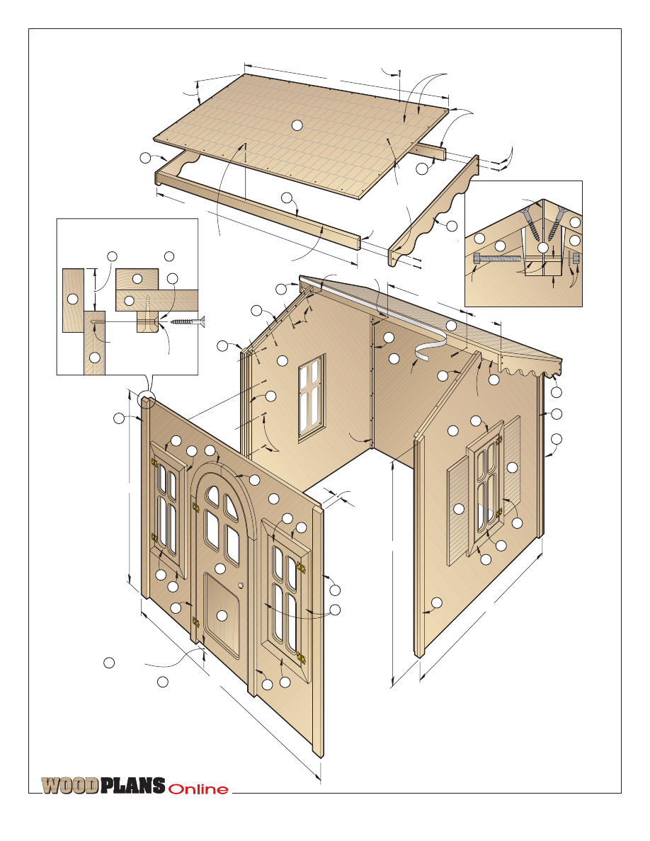
Note: The walls and roof panels disassemble easily when it’s time to store away the cottage.
Even if you don’t make your children or grandchildren anything else
this year, surprise them with this winner of a project. We guarantee
that they’ll spend hundreds of hours in it and cherish every minute.
They’ll think you’re pretty special, too.
Make-believe will abound in this playhouse
Even if you don’t make your children or grandchildren anything else
this year, surprise them with this winner of a project. We guarantee
that they’ll spend hundreds of hours in it and cherish every minute.
They’ll think you’re pretty special, too.
TM
page 1 of 14
DOWNLOADABLE PROJECT PLANS FROM THE EDITORS OF WOOD MAGAZINE
http://www.woodmagazine.com
Make-believe will abound in this playhouse
TM
page 2 of 14
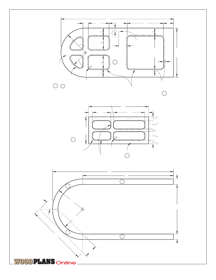
8
1
/
2
"
2" notch 2
1
/
2
" deep
48"
61
1
/
2
"
1
1
/
2
"
END
END
BACK
FRONT
3
/
16
x 1
1
/
4
"
self-adhesive
foam weather
strip between
the roof
panels
ROOF
#8 x 1
1
/
4
" F.H.
wood screws
to attach roof
#8 x 1
1
/
4
" F.H.
wood screws
to attach front
CLEAT DETAIL
(TOP VIEW)
7
/
64
" pilot hole
1
/
2
" deep
5
/
32
" shank hole,
countersunk
1
/
8
"
round-over
on inside
corners of
all cleats
48"
48"
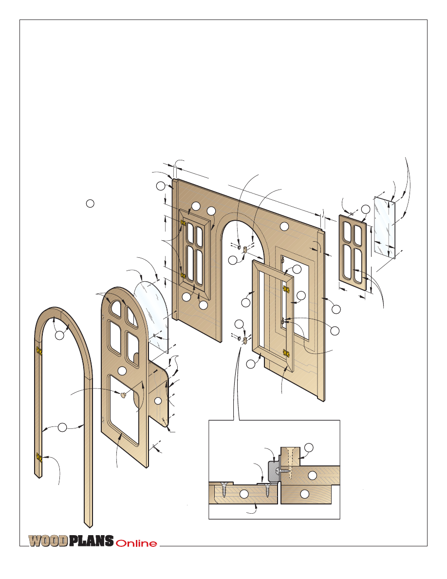
EXPLODED VIEW
1
/
4
" grooves
1
/
8
" deep, cut
using a round-nose router bit
70"
24
o
bevels
#8 x 2
1
/
2
" F.H.
wood screws
5
/
32
" shank holes,
countersunk.
7
/
64
" pilot hole
1
3
/
4
" deep
24
o
bevel
ROOF
68
1
/
2
"
#8 x 1
1
/
2
" F.H. wood screw
#8 x 1
1
/
2
" F.H.
wood screw
24
o
1
/
4
" holes
26
1
/
2
"
1
/
4
x 2"
hexhead bolt
1
/
4
" flat washer
and nut
Foam weather
strip
ROOF DETAIL
1
/
4
" holes
O
Q
O
K
D
J
N
A
O
P
Q
Q
P
K
M
P
D
N
A
O
M
P
K
J
Q
F
L
D
N
H
E
F
J
C
F
B
H
A
C
F
J
C
E
F
L
K
E
G
I
G
F
M
M
3
/
4
"
Overhang equals thickness
of plywood plus batten .
D
K
Bottom edge of
door is 1"
above bottom
edge of front panel .
A
B
TM
page 3 of 14
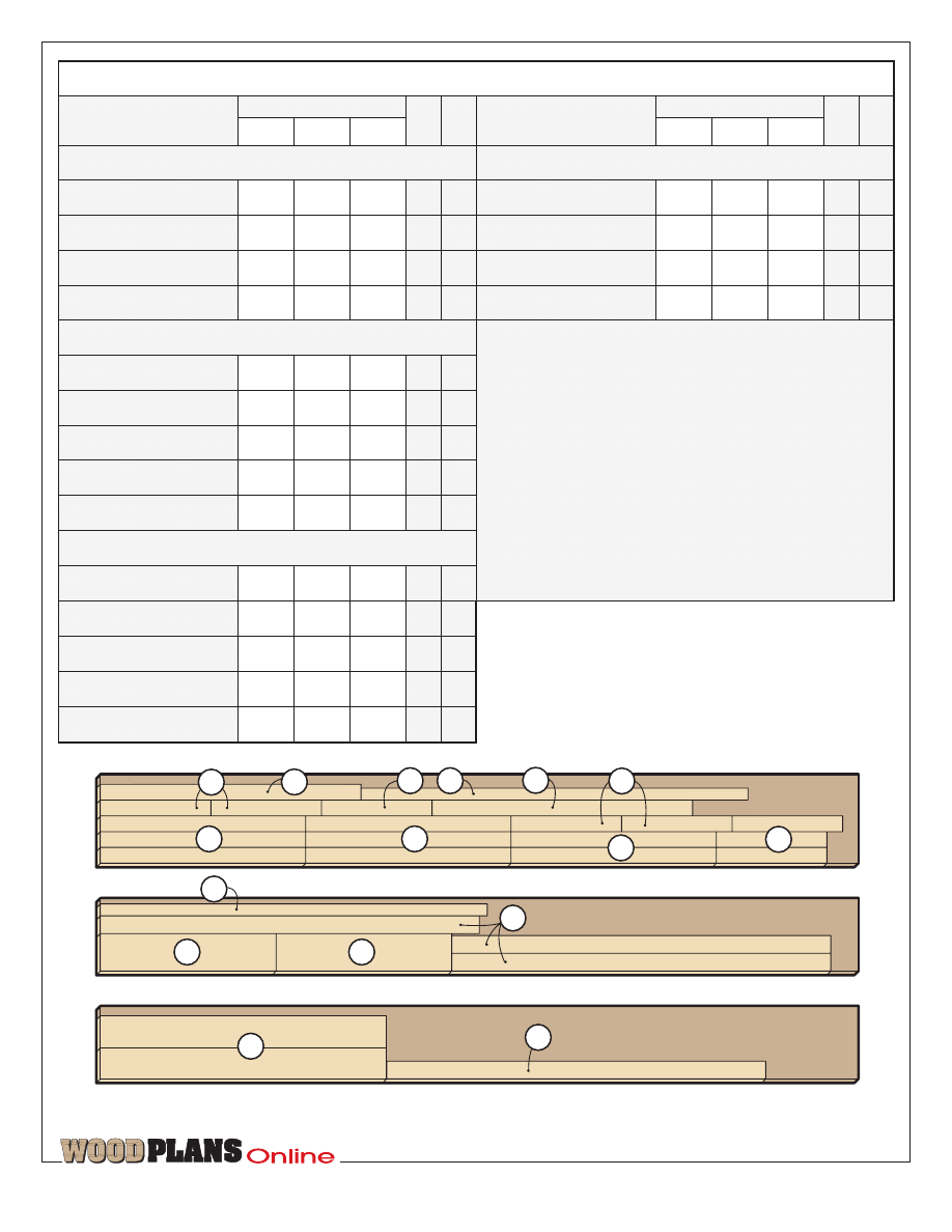
Part
10
Bill of Materials
WINDOW AND DOOR TRIM
R catch supports
C
4
P roof end blanks
C
4
68fi"
‡"
2fi"
C
2"
‡"
‡"
Qty.
O roof panels
70"
‡"
30"
PL
2
T
W
L
Finished Size
Matl.
31‹"
‡"
4"
ROOF AND CATCH SUPPORTS
Q eaves & ridgeboards
D ends
PL
1
B door
PL
4
21Œ"
‡"
9Œ"
PL
2
58‡"
‡"
48"
Materials Key: PL–plywood, C–cedar.
Supplies: 1fi"-diameter wooden knob, 10
ornamental cabinet hinges (Stanley #1475), 10
magnetic catches and strike plates, ¤" acrylic
for window and doors, #6
×
fi" flathead wood
screws, #8
×
1‹" flathead wood screws, #8
×
1fi"
flathead wood screws, #8
×
2fi" flathead wood
screws, 3–‹
×
2" hexhead bolts with washers
and nuts, ‰
×
1‹" self-adhesive foam
weatherstrip, wood putty, acrylic caulk, primer,
exterior latex paints.
Qty.
A front & back
58fi"
‡"
48"
PL
2
Part
T
W
L
Finished Size
Matl.
41"
‡"
17Œ"
FRONT, BACK, AND ENDS
C windows
BATTENS, SHUTTERS, AND CLEATS
E window sides
C
8
26"
‡"
2"
F window tops & btm.
C
8
14"
‡"
2"
G door sides
C
2
33"
‡"
2"
H arched door tops
C
2
22‹"
‡"
4‡"
I door panel
PL
1
14‡"
‹"
13›"
J front battens
C
4
48"
‡"
2‹"
K end battens
C
4
48Ø"
‡"
1fi"
L shutters
PL
4
22"
‡"
7"
M roof cleats
C
4
23Œ"
‡"
‡"
N wall cleats
C
4
48›"
‡"
‡"
3
/
4
x 11
1
/
4
x 96" Cedar
F
E
3
/
4
x 9
1
/
4
x 96" Cedar
J
P
H
3
/
4
x 9
1
/
4
x 96" Cedar
H
K
J
F
G
E
K
F
G
E
F
CUTTING DIAGRAM
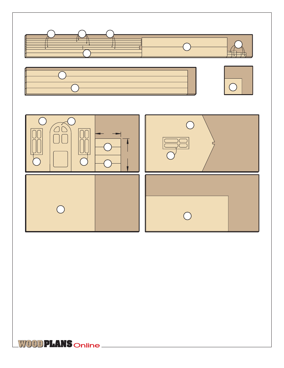
Start with the plywood front,
back, and ends
1 Using the dimensions on page 10
and the layout on the Cutting
Diagram above, mark the outlines for
the front and back (A) on ‡" plywood.
Mark the door and window openings.
(For interior use, we recommend
birch or fir plywood; for outdoor use
you’ll need exterior-grade plywood.
Use the best grade available. The time
you save not having to fill, sand, and
repaint the voids of a less-expensive
plywood will make up for the extra
expense.)
2 Using a straightedge and a circular
saw, cut the front and back panels to size.
TM
page 4 of 14
3
/
4
x 11
1
/
4
x 72" Cedar
Q
1
/
4
x 24 x 24"
Plywood
I
Q
P
R
3
/
4
x 9
1
/
4
x 96" Cedar
K
M
N
M
3
/
4
x 48 x 96"
Plywood
(2 pieces)
D
C
O
3
/
4
x 48 x 96"
Plywood
(2 pieces)
CUTTING DIAGRAM
C
C
3
/
4
x 48 x 96"
Plywood
L
L
A
B
22"
30"
A
3
/
4
x 48 x 96"
Plywood
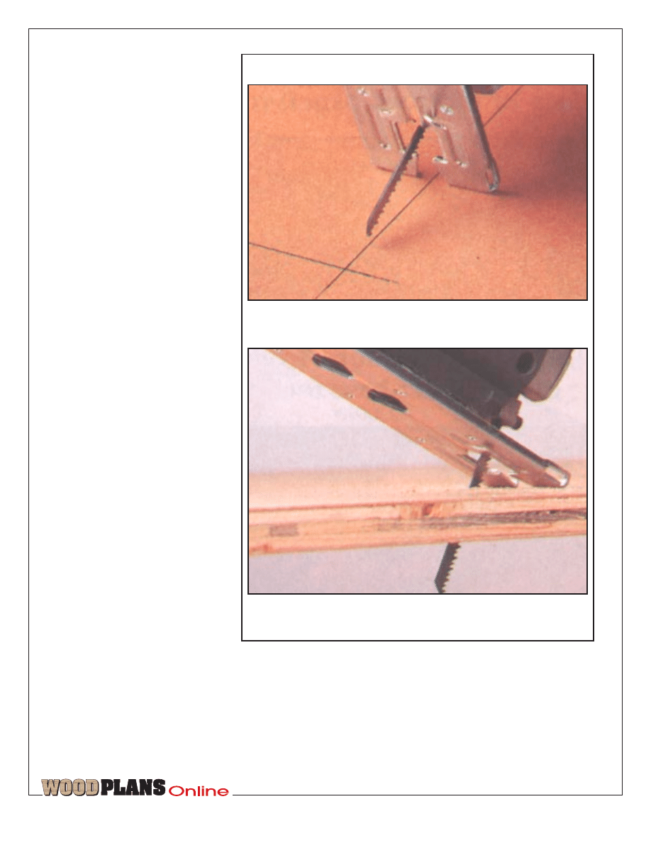
3 To form the openings, use a jigsaw
fitted with a plywood-cutting blade.
Cut the front-door opening to shape,
creating the front door (B). Next, cut
the window openings to shape. (To
avoid drilling blade-start holes when
forming the window openings, we
made plunge cuts with our jigsaw. To
do this, tip the saw as shown in Photo
A. Start the saw (if you have a variable-
speed jigsaw, start with a medium to
high speed and the blade set for straight
reciprocation rather than the orbital
motion). With the front end of the
saw’s bottom plate firmly against the
plywood, lower the reciprocating blade
into the plywood at the marked line as
shown in Photo B. Keeping the front
end of the plate firmly against the
plywood, continue lowering the saw
until the plate is in full contact with
the plywood. Make the cut. Cut
carefully, and save the cutouts: you’ll
use them for the windows (C).
4 Using the dimensions on page 9, lay
out the outline, notch, and window
opening, and cut each end (D) to size.
Again, save the cutout from each end
panel for the windows.
5 Carefully mark the panel openings
on one of the four window cutouts (C),
and cut the four openings in each
window to size. Use a drum sander to
sand the rounded corners.
TM
page 5 of 14
Now, using this window as a template,
mark the openings on the three
remaining windows. Cut and sand the
openings in the windows to shape.
6 Mark the openings on the door, and
cut them to shape.
7 Rout ›" round-overs along the
outside face of the window openings
on the door (B) where shown on the
Front drawing. Switch bits, and rout
‹" round-overs along the outside face
of window-pane openings where
shown on the End drawing.
8 Buy a wooden door knob (we used
a 1fi"-diameter knob), and drill a
mounting hole through the door for
adding the knob later.
Cut the trim, door panel,
and window panel next
1 From ‡" solid stock (we recommend
cedar or redwood), cut the window
trim (E, F) and door-side trim (G) to
size.
2 Using a waterproof glue (we used
Titebond II), glue and clamp the solid-
wood trim around the window
openings.
3 Using the patterns on page 11 for
reference, miter-cut the door-top trim
(H) to size. Then, mark a 9" and 11"
radius on each piece where shown on
the drawing. Cut the pieces to shape,
and check that the inside radius on the
door-top trim is flush with the door
opening. Sand the trim to match. Glue
and clamp the door trim pieces (G, H)
in place.
4 Cut the door bottom panel (I) to the
size listed in the Bill of Materials from
‹" plywood. Drill mounting holes,
and screw the panel to the back side
of the door.
Now, let’s add the battens,
shutters, and cleats
1 Cut the corner battens (J, K) to size.
As shown on the Front and End
drawings, miter-cut the top ends of the
battens to match the roofline on the
ends (D).
2 Glue and clamp the corner battens
(J) to the front and back panels (A),
using a scrap piece of ‡" plywood and
a piece of scrap batten material to
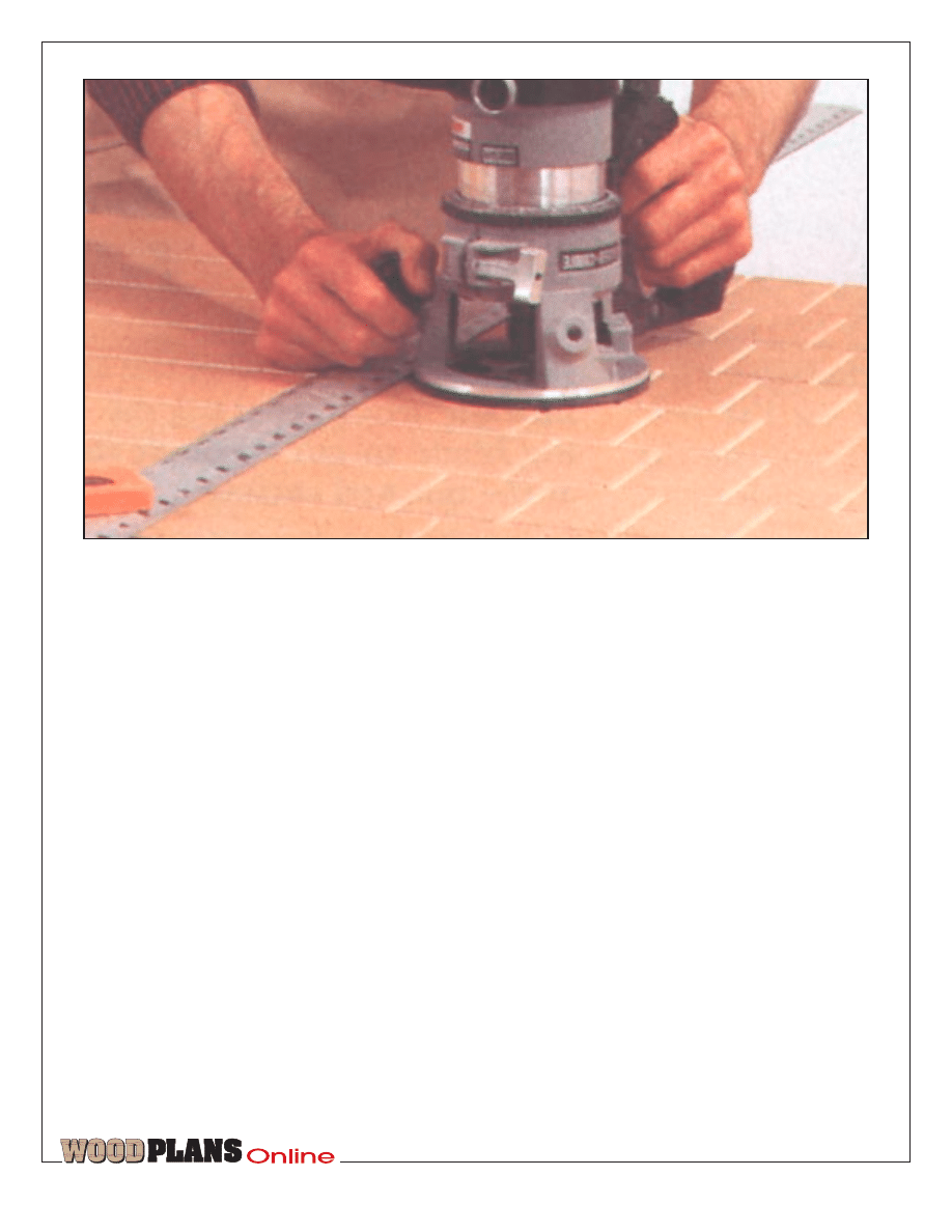
To start the plunge cut for the window, position the jigsaw on
the plywood with the blade not touching the wood but centered
over the cutline.
Turn on the saw, and lower the blade into the wood, causing the
reciprocating blade to cut through the plywood at the marked
cutline.
B
A
gauge the overhang. See the Cleat
detail accompanying the Exploded
View drawing for reference. Also make
certain that the beveled top tip of the
batten is flush with the top edge of the
front panel.
3 Glue and clamp the corner battens
(K) to the end panels (D). Make certain
the mitered top end of the batten is
flush with the top edge of the end panel
and that the edge of the batten is flush
with the outside edge of the end panel.
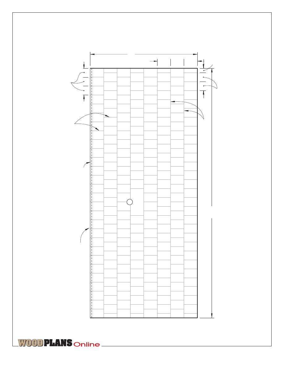
4 To rout the numerous grooves in the
shutters, start by cutting a shutter blank
to 22
×
30" as shown on the Cutting
Diagram. Mark a series of lines 1"
apart across the front face of the 30"-
wide blank. Fit your router with a ‹"
MAKING A PLUNGE CUT WITH A JIGSAW
TM
page 6 of 14
round-nose bit. Using a straightedge,
rout ¤"-deep grooves across the front
of the shutter blank. For reference, see
Photo C for how we used this same
setup to rout the shingle facsimiles on
the roof panels. Cut the four shutters
(L) to size from the large routed blank.
5 Rip ‡" square stock for the roof
cleats (M) and corner cleats (N). Miter-
cut the top end of the roof cleats (M)
to match the notch at the top center of
the end panel.
6 Rout a ¤" round-over along what
will be the inside corner of each cleat
(M, N). See the Exploded View and
accompanying Cleat detail for
reference.
7 Drill countersunk holes for #8
flathead wood screws through the
cleats for securing them to the mating
panels. Glue and screw the cleats to
the end panels.
A roof to keep the rain out
1 From ‡" plywood, cut the two roof
panels (O) to size. As shown on
page 12, lay out the shingle grooves
where dimensioned.
To start the plunge cut for the window, position the jigsaw on the plywood with the blade not touching
the wood but centered over the cutline.
2 Chuck a ‹" round-nose bit in a hand-
held router, and adjust it to cut ¤"
deep. Measure from the edge of the
router base to the center of the bit, and
cut a piece of plywood to this width.
Using the plywood strip as a gauge to
space a straightedge parallel with each
marked line, rout a series of grooves
the length of each roof panel (O).
3 Using the straightedge perpendicular
to the top and bottom edges of the roof
panel, rout the 3‡"-long grooves
between the long grooves to form the
individual shingles as shown in Photo C.
4 Bevel-rip the top edge of each roof
panel (O) at 24°.
5 Cut the roof-end blanks (P) to the
size listed in the Bill of Materials.
Transfer the full-sized roof-end pattern
to one of the blanks. Cut the roof end
to shape, and use it as a template to
mark the other three pieces.
6 Cut the eaves and ridgeboards (Q) to
size. Bevel-rip one edge of each piece
to match the slope of the roof (24°).
7 Clamp the two ridgeboards (Q)
together face-to-face. Drill three ‹"
holes through both ridgeboards where
s h o w n o n t h e R o o f d e t a i l
accompanying the Exploded View
drawing. Later, you’ll fit bolts through
these holes to pull the roof sections
tightly together .
8 Clamp the roof ends (P) and
ridgeboard and eaves (Q) to the bottom
side of the roof panels (O). Check the
fit, and trim if necessary. Now, glue
and screw each roof section together
in the configuration shown on the
Exploded View drawing.
Final assembly and
painting come next
1 With the aid of a helper, clamp and
then screw the ends (D) to the front
and back (A). To save time, don’t drive
all the screws now; do just enough to
hold the pieces together to check the
fit. A cordless screwdriver comes in
h a n d y f o r a s s e m b l i n g a n d
disassembling the pieces.
2 Drill mounting holes, and hinge the
door to the left-hand door trim piece
(G). Hinge the windows (C) to window
trim pieces (E).
C
TM
page 7 of 14
3 Cut 10 catch supports (R) to size,
and use a pair at each window and a
pair at the door to mount the magnetic
catches. See the patterns on page 10
for location and the Magnetic Catch
detail below for reference.
4 Check the fit of the two roof sections
on the walls, and verify that the three
‹" holes align for inserting the ‹"
bolts later. See the Roof detail
accompanying the Exploded View for
reference.
MAGNETIC CATCH DETAIL
(TOP VIEW)
58
1
/
2
"
1
1
/
2
" overlap
1
1
/
2
"
2
1
/
4
"
#6 x
1
/
2
" F.H. wood screws
8"
20"
1
/
8
" acrylic panel,
centered on inside
face of window
21
7
/
8
"
9
7
/
8
"
1
/
4
" round-overs
F
E
C
B
A
Magnetic catch
#8 x 1
1
/
4
" F.H.
wood screw
Magnetic catch
Mitered corner
E
F
I
Strike plate
4"
4"
C
F
E
F
1
/
8
" acrylic centered over
inside face of door windows
#6 x
1
/
2
" F.H. wood screw
3
/
8
" round-overs
Strike plate
#6 x
1
/
2
" F.H.
wood screws
J
J
H
G
1
1
/
2
"-dia.
wooden
knob
1
/
8
" hole
1
/
4
" plywood
centered over
back face of
door cutout
R=1
3
/
4
"
Strike plate
3
/
8
" round-over
FRONT
Ornamental
cabinet hinge
(Stanley #1475)
Ornamental cabinet hinge
(Stanley #1475)
R
R
R
9
/
64
" shank hole,
countersunk
24
o
bevel
Note: The back is made the same
as the front but without any window
or door cutouts.
A
Magnetic catch
Magnetic-catch
strike plate
Door
A
B
G
R
5 Use an exterior wood putty to fill
the screw heads and voids in the
plywood. (Inspect the roof carefully;
we exposed a couple of voids when
routing the shingles. Due to the size of
the voids in the roof, we used acrylic
caulk to seal them rather than the wood
putty.)
6 Remove the catches, strike plates,
and hinges from the assemblies. Prime
all the wood pieces (we used a latex
primer). The edges of the plywood and
the end grain on the solid stock should
have at least two coats of primer,
sanded lightly with 220-grit sandpaper
between coats. Don’t forget to prime
the routed edges at the window
openings.
7 Using an exterior paint compatible
with the primer, paint the house to
match the one shown in the opening
photograph, or paint it to match the
color of your house. (We used an
exterior semigloss latex for the walls,
Produced by: Marlen Kemmet
Project Design: Don Mostrom
Illustrations: Kim Downing
Graphic Design: Jamie Downing
©COPYRIGHT MEREDITH CORPORATION 1997
The purchase of these plans does not
transfer any copyright or other ownership
interest in the plans, the design, or the
finished project to the buyer. Buyer may
neither reproduce the plans for sale nor
offer for sale any copies of the finished
project.
TM
page 8 of 14
24
o
miters
N
M
L
K
F
E
D
C
2" notch
2
1
/
2
" deep
48"
1
1
/
2
"
K
L
M
N
Top end of cleats
stop at notch in top of .
M
D
#8 x 1
1
/
4
" F.H.
wood screws
5
/
32
" hole, countersunk on
back side
#8 x 1
1
/
4
" F.H.
wood screws
3
/
4
x
3
/
4
x 2"
catch support
5
/
32
" hole,
counter-
sunk
1
/
8
x 8 x 20" acrylic panel,
centered on inside face of window
#6 x
1
/
2
" F.H. wood screw
21
7
/
8
"
9
7
/
8
"
1
/
4
" round-overs
Mitered corners
E
F
Strike plate
END
R
Ornamental
cabinet hinges
(Stanley #1475)
1
/
4
" grooves
1
/
8
" deep, cut
using a round-nose router
bit and spaced 1" apart
1"
Fasten shutters with #8 x 1
1
/
4
" F.H.
wood screws from inside.
CLEAT DETAIL
24
o
3
/
4
"
Inside face
of ends
5
/
32
" holes,
countersunk
on inside,
drilled for
attaching
the roof and
wall pieces
#8 x 1
1
/
4
" F.H.
wood screw
M
N
D
1
/
8
" round-over on
inside corner of
all cleats
D
K
Magnetic catch
(see detail on Front
drawing for reference).
both inside and out. Then, we used an
exterior gloss for the door, windows,
trim, shutters, door knob, and roof.)
8 Screw the shutters in place.
9 Using a fine toothed-blade, cut ¤"
acrylic for the doors and windows. See
the patterns on page 9 for size and
shape. Drill mounting holes, and
secure the acrylic in place with #6
×
fi"
flathead wood screws. Be careful
not to over-tighten the screws; too
much pressure can cause the acrylic
to crack.
10 Reattach the door and windows.
Adhere the weather strip to one edge
of an assembled roof section where
shown on the Roof detail accompanying
Exploded View drawing.
11 With the aide of a helper,
reassemble the cottage front, back, and
ends. Check for square. Position the
roof sections in place. Then, use three
‹" bolts and nuts to pull the roof-
sections/ridgeboards tightly together.
Secure the roof sections to the cleats
(M) with #8 wood screws.¿
TM
page 9 of 14
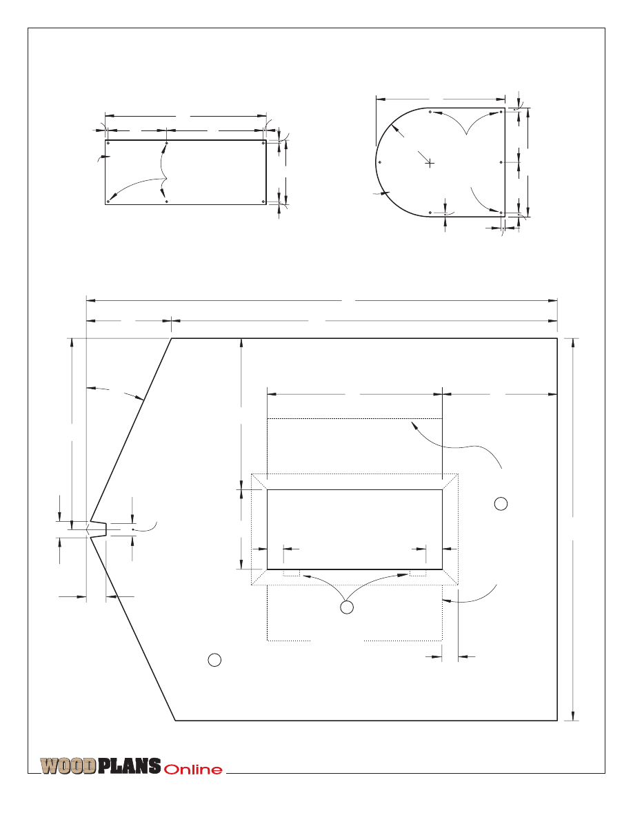
R=6
3
/
4
"
6
3
/
8
"
16"
9
/
64
" holes
,
countersunk
1
/
8
" acr
ylic
DOOR WINDO
W
3
/
8
"
6
3
/
8
"
13
1
/
2
"
3
/
8
"
3
/
8
"
3
/
8
"
20"
8"
12"
WINDO
W
(4 needed)
3
/
8
"
7
1
/
4
"
9
/
64
" holes
,
countersunk
3
/
8
"
3
/
8
"
3
/
8
"
1
/
8
" acr
ylic
2
1
/
2
"
24"
48"
24
O
22"
10"
19"
Mount shutters here
.
2"
2"
2"
1
9
/
16
"
10
11
/
16
"
58
3
/
4
"
14
1
/
2
"
2"
D
END
(2 needed)
48
1
/
16
"
L
Mount
magnetic-
catch
suppor
ts
here
.
R

TM
page 10 of 14
22"
10"
48"
4"
10"
4"
18"
6
1
/
4
"
R=9"
42"
FR
ONT
2"
2"
4"
26"
58
1
/
2
"
6
1
/
4
"
14
1
/
2
"
The bac
k is the same siz
e as the front.
The bac
k has no cutouts f
or the windo
ws and door
.
29"
A
A
A
Mount
magnetic-
catch
suppor
ts
here
.
R
TM
page 11 of 14
G
H
G
R=9"
R=1
1"
18"
2"
2"
44"
DOOR TRIM
33"
22
1
/
4
"
45
O
4
3
/
4
"
H
R=1" on all
inside
cor
ners
Windo
ws are made from
windo
w cutout and from front
and end pieces
.
1"
1"
9
7
/
8
"
1
/
4
"
round-o
v
ers
1
1
/
2
"
6
5
/
8
"
21
7
/
8
"
11
1
/
4
"
1
1
/
2
"
1
1
/
2
"
2
15
/
16
"
1
1
/
2
"
2
15
/
16
"
WINDO
W
(4 needed)
C
C
3
3
/
4
"
4
15
/
16
"
41"
R=1" on all
inside
cor
ners
3"
2"
3"
2"
7
1
/
2
"
1
/
8
" hole f
o
r
door-knob
scre
w
3"
DOOR
4
15
/
16
"
3
/
8
" round-o
v
e
r
along front
edge
1
1
/
2
"
3
1
/
4
"
6
1
/
2
"
13
1
/
4
"
11
7
/
8
"
17
7
/
8
"
3
/
8
"
round-o
v
ers
along front
edge
Door is made from
door cutout from the
front .
B
A
B
R=5
15
/
16
"
R=8
15
/
16
"
3
/
4
" o
v
er
lap
of opening
in bac
k side
of the door
I
TM
page 12 of 14
70"
T
op edge of roof
24
O
be
v
e
l
1
/
4
" g
roo
v
es
1
/
8
" deep
, cut
using
1
/
4
" round-nose router bit
and stopped where sho
wn
2
1
/
2
"
3
3
/
4
"
30"
1
/
4
" g
roo
v
es
1
/
8
" deep
, cut
using
1
/
4
" round-nose router bit
3
3
/
4
"
3
3
/
4
"
2
1
/
2
"
1
1
/
4
"
R
OOF
(2 needed)
O
TM
page 13 of 14
P
4"
24
O
R
OOF END
24
O
29
5
/
8
"
31
1
/
4
"
24
O
5
/
32
" shank holes,
countersunk
4"
fi
‹‡
1"
SCALE
To ensure full-sized patterns are correct
size, your printer should be set to print
at 100% (not fit to page). Measure full-
sized patterns to verify size.
TM
page 14 of 14
5
/
32
" shank holes,
countersunk
24
O
R
OOF END
(4 needed)
P
Wyszukiwarka
Podobne podstrony:
50 straw bale house plans
Wood Working Plans for 6 inch Turret Lathe
3 Wood Working Plans
eBook Home Wood Working Plans
Wood Working Plans
Woodwork Wood Working Plans
Mini Country house
Mini Country house
eBook DIY Woodworking Plans Guide To Wood Finishing
Diy Workshop Woodwork Plans Drawings For Homemade Wood Lathe
Wood Working Plan Arcade Cabinet Plans
Playhouse How to make a Wendy House
Playhouse SIMPLE TREE HOUSE
Ethel Cook Eliot The Little House in Fairy Wood
Wood Magazine America s Best Home Workshops 2009 Bonus Plans
(Ebooks) Diy Woodwork Plans Bending Wood
ĆW 4 Country
więcej podobnych podstron