[Arrangements have been made to supply the necessary castings for this lathe, at a low figure, to any who are
interested. This magazine has no financial or other interest in this, beyond that of service to the reader. The name
and address of the maker will he furnished, upon request, by the Shop Notes Department, Popular Mechanics Magazine,
6 N. Michigan Ave., Chicago.—Editor.]
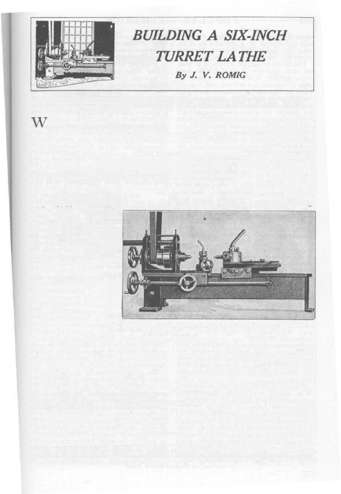
HILE the turret lathe is essentially
a tool for the production of work in
large quantities, a 6-in. lathe of the type
described in this article will be found
exceedingly useful in the small experi-
mental shop. With a center held in the
main turret, the machine may be used
as a simple engine lathe, and when a
number of similar pieces are to be turned
out in a hurry the work may be per-
formed in almost as expeditious a manner
as on a commercial turret lathe.
This machine was built and used by the
the spindle first, then re-center and finish
the outside. The nose is taper-bored to
take the collets, and threaded eight
threads per inch, U. S. standard, to fit
the faceplates and chucks. The taper seat
for the collets should not be finished until
the lathe has been completely assembled;
it should then be machined with tools
held in the toolpost of the lathe itself.
The inner races of the ball bearings
should be a good fit on the flat threads
on the rear of the spindle, and on the out-
side of the spindle at the front. Bearing-
author in his own work-
shop, on fine precision
work, and many accurate
jobs have been done with
it very quickly. Most of
the work of building can
be done in a workshop
equipped only with a vise
and bench drill, with the
necessary small tools, as
flat cold-rolled steel is
used for the ways, car-
riage, and other parts of
that character; it will be
necessary, however, to
have certain things, such
as the machining of the
headstock and the cutting
of the feed screw, done
Photograph of the Completed Lathe as Used in the Author's Workshop: It
Is Capable of Performing Both Fast and Accurate Work
in a machine shop, but this is a small item.
The headstock is made of gray iron, and
is fitted with an overarm steadyrest,
which allows the carriage to travel the
full length of long work, as the work is
supported from the top and rear. The
spindle is carried, at the rear, by a double-
row ball bearing, .75 in. wide, of the com-
bined axial and radial-load type, and at
the front by a single-row bearing, .629 in.
wide. Both of these bearings have an
outside diameter of 2.441 in., and an inside
diameter of 1.181 in. Care must be taken
to bore the bearing housings a push fit
for the bearings, and to have all faces
square and parallel with each other.
The spindle should be made of a good
grade of steel, of about .3-per-cent carbon
content, and is hollow. It is best to bore
retaining rings are fitted at the rear,
clamping the outer race of the bearing
firmly, and taking up the end thrust.
These are fitted with felt dust rings, bear-
ing on the collars on the spindle; the
rings at the front are also fitted with dust
rings, running on the spindle, but these
rings do not clamp the single-row bear-
ing, which is permitted to float.
When the headstock is assembled, the
bearing housings should be packed with
a good grade of vaseline, which will last
a long time; see that the vaseline supply
is at all times sufficient for good lubrica-
tion. Spindles fitted in this manner are
far superior to those fitted with plain
bearings, as they consume less power, are
free from vibration, and allow of accurate
as well as heavy work. The writer has
3841
3842
P O P U L A R M E C H A N I C S
taken a 1/8-in. cut on a piece of 1/2-in.
cold-rolled steel at a distance of 5 in.
from the collet, the reduced diameter
being very accurate as to size.
The drawbar for the collets is a tube,
the outer diameter of which fits the bore
of the spindle. It is threaded at the f r o n t
to fit the collets, and is fitted with a hand-
wheel at the rear. A tiebar at the top of
the headstock keeps the two arms stiff
and rigid. The cone pulley is fastened to
the spindle by a setscrew, spotted into
the spindle; two cone pulleys, of the same
size, should be cast and machined, one
being used on the countershaft. The arm
for the steadyrest is a length of 1-in.
must be as true and straight as it is pos-
sible to make them, as upon their truth
depends the accuracy of the lathe. When
trued, all surfaces should either be frosted
or polished.
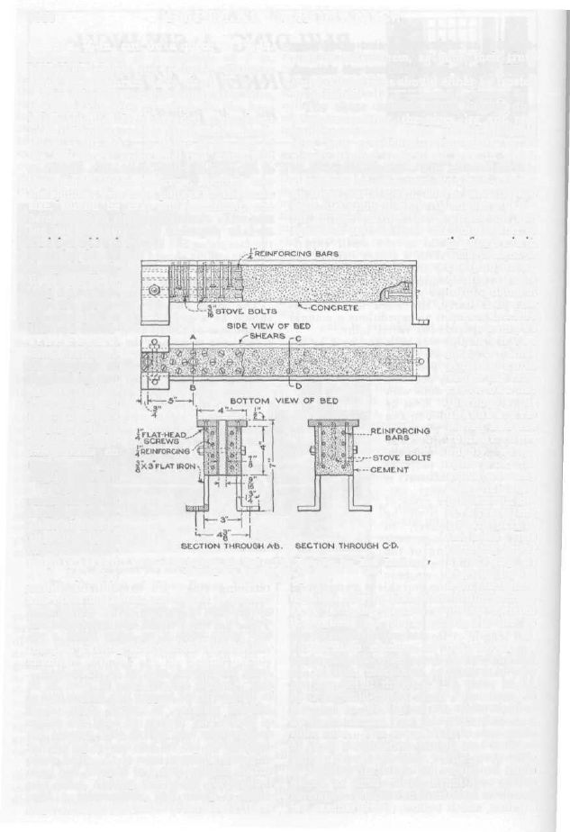
The shear anchor bolts should now
be screwed home, the pipes, leg and rear
leadscrew-bearing bolts placed in posi-
tion, and a wooden form made to fit
closely around shears and legs, in which
to pour the cement. The cement used is
a mixture of one part Portland cement
to three parts clean, sharp sand, mixed
with just enough water to enable a hand-
ful of the mixture to be picked up and
squeezed and to leave the impression of
c o l d - r o l l e d
s t e e l ; i t i s
clamped in posi-
tion by 3/8-in.
c a p s c r e w s ,
w h i c h c o m -
p r e s s t h e
s l o t t e d h e a d -
s t o c k a r m s .
The headstock
is fastened to
the bed
by two
1/2- i n. b o l t s ,
r u n n i n g u p
through pieces
of pipe cast in-
to the
bed;
by
this means no
strains are put
on the cement.
T h e
c o n -
struction of the
bed is some-
what of a nov-
elty, although it
has been thor-
o u g h l y t r i e d
o u t
b y t h e
writer in this
the fingers in it.
This cement is
t a m p e d d o w n
firmly
in the
form, poking it
a r o u n d t h e
screws and into
t h e c o r n e r s
w i t h a n i c e
pick, or some
s i m i l a r tool.
When the con-
crete has set
thoroughly, the
b o a r d s are re-
moved and the
c e m e n t t h o r -
oughly wetted
twice a day for
about a week;
this will temper
the cement, and
is a very im-
portant part of
the work. The
resulting bed is
as s t r o n g as
a n y o n e c o u l d
wish. Reinforc-
ing rods may be laid down in the cement,
as it is being placed, or wires twisted
throughout the bolts, adding further to
the strength of the bed.
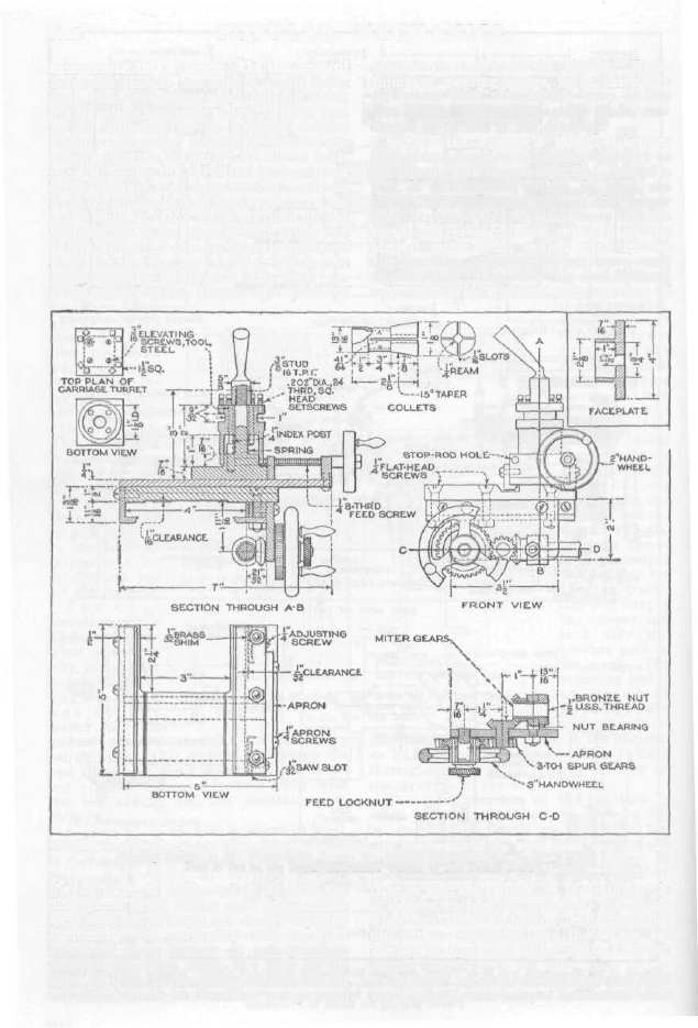
The main member of the carriage is
made of cold-rolled steel, 1/2 by 5 by 5 1/4
in. in size, machined as shown in the
carriage-detail drawing. A piece of 1/4
by 2-in. cold-rolled steel, 7 in. long, is
fastened to the top of the main member
by 3/16-in. screws; on this piece the cross
slide runs. The cross slide is also made
of steel, machined as shown, and is fitted
with a turret toolpost. The cross slide
is held to its ways by means of angle
pieces, as shown in the front view of the
carriage. The turret is made of steel, and
is casehardened; four tools can be
and other machines, and found to be very
satisfactory. This method of making the
bed eliminates the hardest work of mak-
ing a small lathe, as it does away with
the bed casting and the necessary ma-
chining.
A piece of 1/2 by 4-in. cold-rolled steel,
30 in. long, is used for the shears. This
is first drilled and tapped for a number of
3/16-in. stove bolts, of varying lengths,
which are used to anchor the shears to
the cement, also drilled and countersunk
for the leg screws and for the 1/2-in. head-
stock bolts. It is next carefully straight-
ened and scraped to a true surface on top
and sides, testing the width throughout
with a micrometer, and using a knife-
edge straightedge on the surfaces; these
Method of Making the Bed: The Bolts for the Rear Leadscrew
Bearing are Not Shown, but should be Cast
In like the Leg Bolts
3844
P O P U L A R M E C H A N I C S
mounted in this at once. On the boss of
the cross slide is mounted a small index
post, into the countersunk top of which
the elevating screws fit, allowing each tool
to be adjusted to its correct cutting
height. A spring pushes the turret up-
ward when the clamping handle is loos-
ened, allowing the turret to be turned to
bring another tool into cutting position.
A 1/4-in. square-thread screw operates the
cross slide, and the tools are held in the
toolpost by 1/4-in. square-head setscrews.
The apron of the carriage is made of
steel, 2 in. wide, and is fastened to the
main carriage member by flat-head ma-
chine screws. The front angle piece of
against the edge of the shears. Brass
shims, or wearing pieces, 1/32 in. thick, are
set in the ends, to take the wear on the
filler piece. The rear angle is plain, ma-
chined as shown in the drawing.
Behind the apron is fitted a bronze
nut; this rotates in a bearing fastened to
the apron, and is screwed into one of a
pair of miter gears, which, in turn, are
driven by 3-to-l spur gears; the larger
gear is pinned to the handwheel, and the
smaller is pressed onto the hub of the
second miter gear, which runs in the
apron. The handwheel runs on a stud
screwed into the apron; this stud is fitted
with a knurled friction nut, so that, if
Full Details of the Carriage and Apron Mechanism: Note the Employment of the Small Index Post and Ele-
vating Screws in the Toolpost to Secure the Correct Height for Each Tool. The
Post is Set in the Inner Left-Hand Corner of the Turret Base
the carriage is built up, as shown, the
filler piece being slit at each end, so that
wear may be taken up as it develops, by
tightening the adjusting screws. The
holes for these screws do not go clear
through the filler piece, but stop at the
slits, so that, by screwing the screws in,
the inner ends of the filler are pressed
change gears are fitted to the lathe or it
is desired to feed by means of the hand-
wheel on the end of the leadscrew, the
nut can be tightened and the whole as-
sembly of spur and miter gears and nut
locked firmly.
The rear, or main-turret, base and slide
are made of cast iron, a dovetailed slide
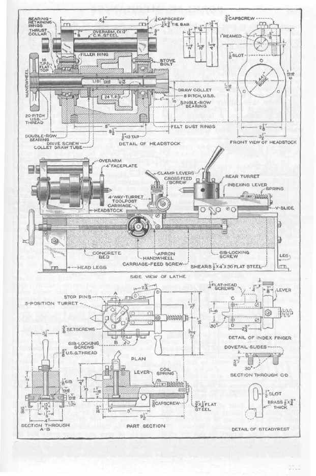
Details of the Headstock and Main Turret, and Side Elevation of Completed Lathe: When a Center is Used in
the Turret, as Shown, and the Gib-Locking Screw Tightened, the Tool can be Used as an Ordinary Bench Lathe,
for Turning Work between Centers. Five Tools can be Used in the Main Turret, and Four in the Toolpost
Turret, Making for Speed in Production
3843

being used, fitted with a 1/8-in. gib. The
front gib-adjusting screw is fitted with a
handle and is used to lock the turret in
position for plain turning operations.
The turret pivot pin, of cold-rolled steel,
casehardened, is 5/8 in. in diameter, with
a 5/8-in. U. S. standard thread cut on the
upper end, and fitted with a clamping
handle. The turret is made of steel, under-
cut as shown in the drawings, and has five
equally spaced slots milled around the
lower surface for the index finger. One
side of each slot is radial, the other being
tapered, and the index finger is made to
correspond. By making the finger and
slots of this form, the radial side does the
actual locating, and the tapered side
moves the turret to position; only the
radial side need be of great accuracy,
while the wear is chiefly on the inclined
side, where it does no harm.
The holes for the tools should not be
bored until the indexing mechanism has
been assembled and the lathe set up;
then, by boring the holes with a tool held
in the chuck, and correctly supported, the
greatest degree of accuracy is obtained.
The details of the indexing device are so
complete that little description is neces-
sary; care should be taken, however, to
see that the coil spring is heavy enough
to prevent the index finger from being
withdrawn from the turret until the stop
pin on the back of the turret base strikes
the pin on the slide; the backward move-
ment of the lever will thus move the
whole turret back until the stop pins en-
gage; further movement disengaging the
index finger, and allowing the turret to be
revolved to the next position. The index
finger slides between beveled strips of
3/16-in. steel, and must be a good fit; both
slides and finger should be casehardened
to insure long life.
The speed of the lathe, and the arrange-
ment of the countershaft, will be deter-
mined by the work to be undertaken and
the shop conditions. A reversing coun-
tershaft should be fitted if tap and die
work is to be performed on the lathe. A
quadrant and stud can be fitted on the
head end, and a set of change gears pro-
vided, if the lathe is to be used for screw-
cutting; in this event, no care should be
spared to secure an accurate leadscrew.
The builder of this lathe will have a
very efficient machine, one that could not
be purchased for many times the cost of
building.
Wyszukiwarka
Podobne podstrony:
3 Wood Working Plans
eBook Home Wood Working Plans
Wood Working Plans
Woodwork Wood Working Plans
Wood Working Plan Arcade Cabinet Plans
Garret Water Carburator Plans For Water Powered Vehicles
Plans For Wind Generator Pt250 Blade Plan10A
My plans for the future
G20 in Mexico – New Plans for EU
Garret Water Carburator Plans For Water Powered Vehicles
Plans for horizontal Bench Mill
Plans for Bench Grinder
Plans for radial drill press
England s Place in Hitler s Plans for World Dominion
Plans For Steam Marine Engine
Woodwork Plans For Hydraulic Press
Wood House Plans Kids Country Playhouse
więcej podobnych podstron