Model Marine Engine
Requires No Castings
214 POPULAR SCIENCE
EXHAUST PORTS
No. 29 DRILL
No. 29
DRILL
(STEAM
PORT)
CYLINDER BLOCK
No.
31
DRILL
CROSSHEAD-GUIDE
BRACKET
REAM
CYLINDER COVERS
TAP
6
- 32
R
No.29
DRILL
(STEAM
PORT)
CYLINDER SUPPORT
No.31 DRILL
VENT,
No.50 DRILL
VALVE LINER
CROSSHEAD
GUIDE
FLYWHEEL
THREAD
18
5 - 40
THREAD
STEAM INLET.
DRILL
REAM
MAIN BEARING
GLAND
5 - 40
THREAD
COLUMN
10
- 32
THREAD
ENGINE ASSEMBLY
10
- 32 TAP
4-46 TAP
BASE
STEAM MANIFOLD
(INTAKE)
No.51
DRILL
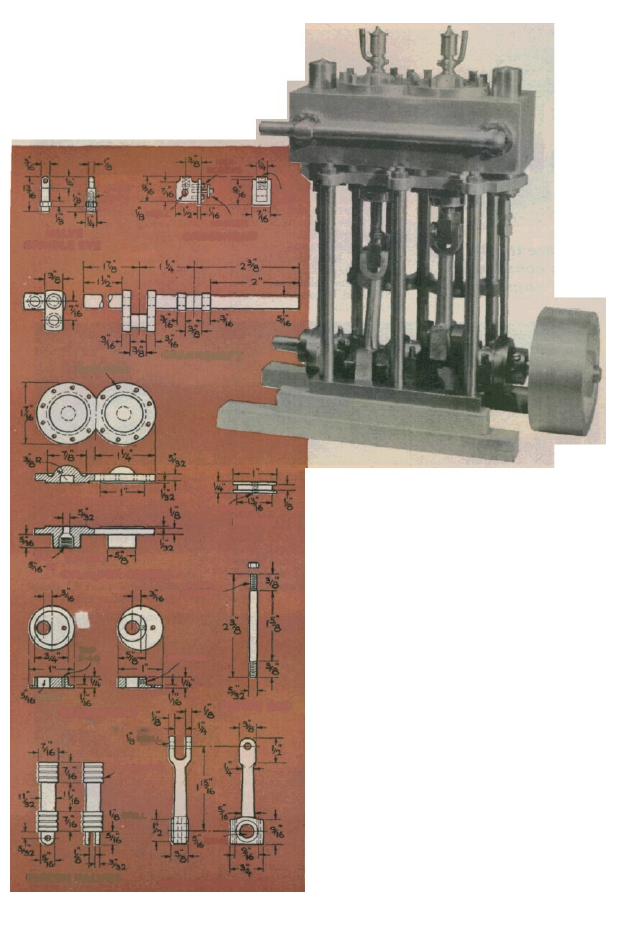
Building this power plant looks
tricky, but it is just a series
of simple operations. Follow
them in photos from A to Z.
By C. W. Woodson
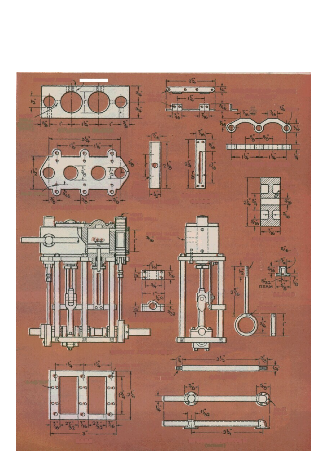
LTHOUGH the little two-cylinder steam
engine above has been simplified for
easy construction, this does not show in
performance or looks. The model has two
double-acting cylinders with inside-admis-
sion piston valves. Bore is 1" and stroke .875".
Steam is exhausted through ports drilled in
the cylinder walls, greatly simplifying the
valve gear.
Reverse gear has been omitted for sim-
plicity, but the engine can be made to run
in either direction by resetting the eccen-
trics. Slip-eccentric reversing could be
added easily.
With 75 lb. of steam or air the engine
will kick over at about 1,100 r.p.m., provid-
ing ample power for a 48" to 60" model boat.
All parts are machined from scrap-bin
pieces of brass, bronze, dural and steel.
After the final assembly, pour a bit of water-
diluted Noxon silver polish into the cylinders
and valve liners and rotate the crankshaft
by hand to lap the moving parts to a smooth
fit. Then wash the polish out, oil all parts,
and full steam ahead!
JANUARY 1953 215
Please turn the page for A-to-Z photos.
A
HEX
SCREWS
DRILL
WASHER.
5 - 40
TAP
CROSSHEAD
VALVE
SPINDLE EYE
CRANKSHAFT
No.31 DRILL
(UPPER)
PISTON
TAP
6 - 32
(LOWER)
TAP
18
CYLINDER COVERS
6
- 31
THREAD
TAP
5 - 4O
ECCENTRICS
REAM
PISTON ROD
TAP
5 -
40
DRILL
V - GROOVES
DRILL
PISTON VALVES
CONNECTING ROD
REAM
6-32
TAP
216 POPULAR SCIENCE
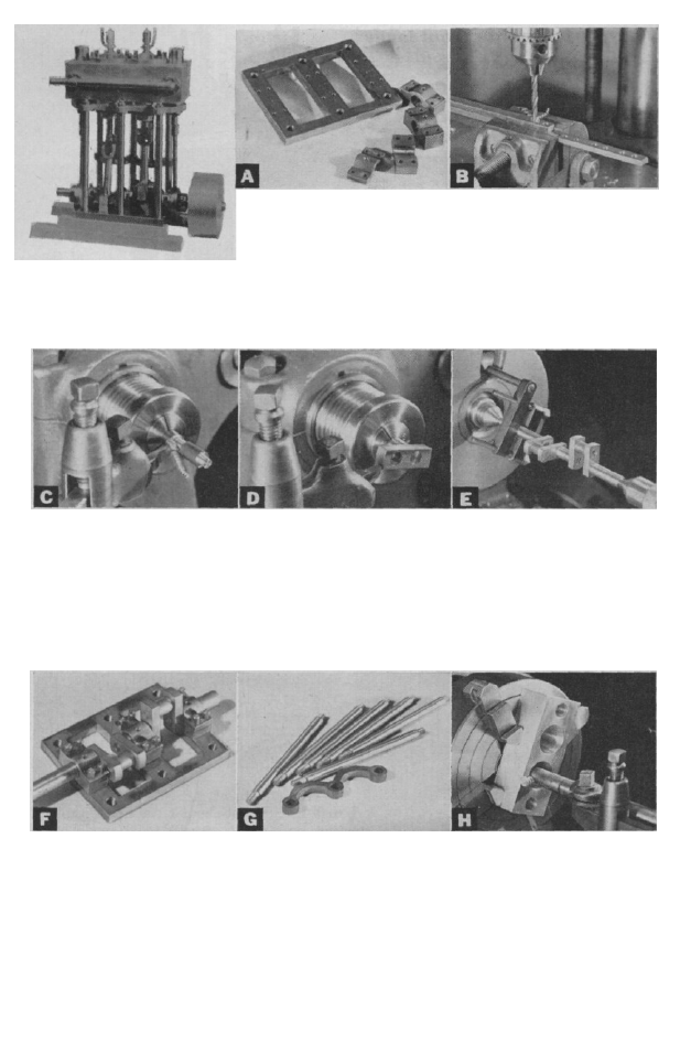
All set up. Prior to installing Crosshead-guide support, Cylinder block is solid chunk
crankshaft, main hearings are shown with columns, is cut of brass or bronze. Lay out
aligned by slipping them on a from ¼" brass plate. Three centers for cylinders and valve-
straight piece of .312 drill holes are drilled first, using the insert holes and bore out 1"-
rod and clamping in position. base as a spacing jig, and then dia. cylinders in lathe. Make
Holes are t h r u drilled in base layout of shape is made, using final pass with a honed, round-
for mounting screws. All hex- holes as reference points. Col- nose boring bit fed slowly for
head screws are turned from umns are ¼" drill rod cut to maximum smoothness. Cylin-
.125" steel hexagon rod and length, shouldered for ¼" at der is lapped with Noxon silver
threaded 4-48. Corners of hex bottom, .375" at top and threaded polish after assembly, then
heads are rounded and polished. 10-32 at both ends. washed and oiled.
C r a n k p i n s and crankshaft Web ends are finished and Completed c r a n k s h a f t is set
ends are made from .312 drill brought to dimension in the up between centers and tested
rod. Turn both ends of the pins lathe. As each web is forced for accurate alignment. Crank-
and the inner end of the shaft onto a shaft or crankpin sec- pins are set at 90°, giving shaft
sections .002" oversize for a tion, it is chucked and turned a smooth-running quality with
force fit in the .188 reamed to an .687 radius from the four evenly spaced impulses
holes in the webs. As no tru- center of the far hole. It is not to each revolution. This allows
ing cut is made on the crank- necessary to pin the force- it to run without a flywheel,
p i n s u r f a c e s , the d r i l l rod fitted webs to the shaft, but although performance is im-
should be held in a collet or driving pins in undersize holes proved if one is used. Chances
indicated true. is extra insurance. of stalling are also lessened.
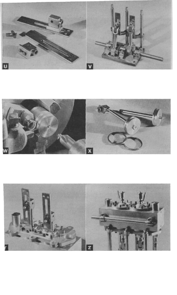
Here are the 26 steps
in the construction
of the engine.
Base and main bearings. Crankshaft webs are cut from
Brass base plate, ¼" thick, is steel bar stock, .188 by .375.
cut out for two crankcase wells. Shaft holes are drilled .437
Large holes, tapped 10-32, are apart, using jig to assure uni-
for supporting columns; small form spacing. After drilling,
holes, tapped 4-48, are for the webs are cut off, stacked
bearings. Main bearings are in a drill-press vise and reamed
two pieces of ¼" brass soldered to make absolutely certain
together for machining, then holes are spaced right. Ends
unsoldered to form upper and of webs are machined later in
lower sections. the lathe.
Valve-insert holes are reamed
½". Intake and exhaust ports
are drilled. Valve liners—½"
brass tubing—are drilled in one
wall. Liners are then turned
180° to line up holes with
ports and locked with set-
screws in block end. Steam-
inlet holes are drilled through
block and one wall of liner
from front of block.
Cylinder covers are turned
from 1½" brass rod. Inside face
of upper and lower covers are
turned to a snap fit in cylinder
bore, using cylinder as gauge.
Then they are cut off, reversed
in the chuck and finished.
Piston-rod packing-gland hole
should be drilled and tapped
in lower cover before cutting
off.
Packing glands (at right in
photo above), are t u r n e d from
.625 brass rod and threaded to
fit lower cylinder cover. Gland
is drilled and reamed .156
for piston rod and upper end
of hole is counterbored for
packing. Four .063 holes in
flange are for adjusting pin
to tighten flange on graphite
packing.
Valve eccentrics are made in
two parts and joined by a sin-
gle setscrew. The body or bear-
ing was turned in the three-
jaw chuck; the cover plate
with off-center collar, in four-
jaw chuck. The collar is drilled
in the lathe, then used as a jig
to locate the hole in the body.
Straps are thick-wall tubing of
proper inside diameter.
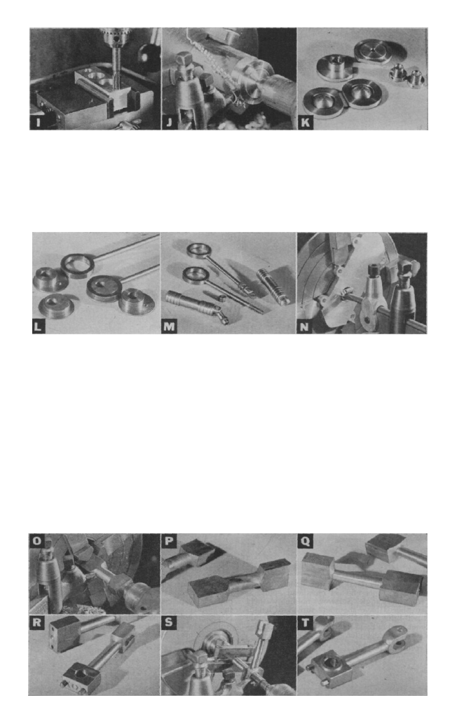
Piston valves, turned from
mild steel, should be perfect fit
in valve liners. Oil grooves are
cut with V-shaped cutter bit.
Lower ends are slotted and
drilled for adjusting eyes,
which are threaded onto ec-
centric rod and held in proper
adjustment by lock nuts. Rods
are threaded into eccentric
straps.
Cylinder-block support is cut
from .188 brass plate. Holes
for supporting columns must
match those in base. Support
is chucked in lathe and bored
to receive the .375 collars of the
lower cylinder covers. Six No.
38 holes for the screws that
join plate to underside of block
are then drilled according to
the layout.
Connecting rods, developed from lengths of
steel bar stock, are made in successive stages:
( O ) The steel bar is centered in the four-jaw
chuck, centerdrilled at the free end, and support-
ed by the tailstock center while the middle sec-
tion is rough-turned. (P) The big end is then
clamped in a vise, the rod heated almost white
hot and the small end bent at right angles to the
big end. ( Q ) When cool, it is set up in the lathe
again and turned to finished size. ( R ) The little
end is then cut out and filed to shape and the big
end drilled for the two bearing-cap screws. The
bearing cap is cut off the big end, t h e m e e t i n g
surfaces smoothed, and then joined with the two
cap screws.
The crankpin hole is then drilled and reamed
.312. ( S ) The big end is clamped on a
mandrel and turned to shape, and the little
end is drilled for a .125 rivet that links it to the
crosshead. ( T ) The finished con rod looks like
this after machining.
Turn the page for the six final steps.
Crossheads are shaped from ¼" brass and a
slipper of .063" brass is soldered on foot. Any
error in the crosshead-guide support can be
made up by altering the thickness of the slipper
plate. The heads of two hex-head screws ride in
slotted crosshead guide; setscrew and washer
hold assembly together.
Trial setup. Smooth action of moving parts is
checked by setting up lower half of engine and
rotating crankshaft by hand. Crosshead-guide
support should be placed in proper position on
columns to check crosshead travel in slot. Upper
ends of guides are later supported by bracket on
upper assembly.
Pistons are turned from brass or dural rod to an
easy fit in the cylinders. Parting tool is used to
cut groove for piston ring. Center of piston is
drilled and tapped for 6-32 thread on upper end
of piston rod. Piston is then faced, cut off and
reversed in the chuck for facing opposite end
and bringing to dimension.
Cast-iron piston rings, of standard 1" size, are
purchased commercially and fitted to pistons.
Lower end of piston rod is threaded 6-32 to fit in
crosshead. Lock nut is tightened against top side
of piston after upper end of rod is threaded into
center hole to prevent piston from working loose
on piston-rod threads.
Upper assembly is tested for smooth action,
bracket for upper ends of crosshead guides is
cut from brass angle. Setscrews holding washers
to crossheads have shoulders turned to length
that will bring washers up against slotted guide
without forcing them tight. Setscrews join cylin-
der support to cylinder.
218 POPULAR SCIENCE
Petcocks on cylinder covers are dummies but
could be drilled and used as gravity-feed oil
cups. A displacement oiler should be fitted for
model-boat use. Caps for valve liners are drilled
No. 50 to vent space above valves; they are
turned to a snap fit. Intake manifold is ¼" tubing
soldered into turned fittings. END
Wyszukiwarka
Podobne podstrony:
Vertical Steam Marine Engine
plans for occilating steam engine 1185
Garret Water Carburator Plans For Water Powered Vehicles
Plans For Wind Generator Pt250 Blade Plan10A
My plans for the future
Brayton Cycle The Ideal Cycle For Gas Turbine Engines
G20 in Mexico – New Plans for EU
Garret Water Carburator Plans For Water Powered Vehicles
Hydrogen Gas Injector System For Internal Combustion Engine
Plans for horizontal Bench Mill
caterpillar c18 marine engine maintenance intervals
Plans for Bench Grinder
SMeyer CA1233379A1 Hydrogen Gas Injection for Internal Combustion Engine
Wood Working Plans for 6 inch Turret Lathe
Plans for radial drill press
England s Place in Hitler s Plans for World Dominion
więcej podobnych podstron